US5097934A - Coin sensing apparatus - Google Patents
Coin sensing apparatusDownload PDFInfo
- Publication number
- US5097934A US5097934AUS07/491,245US49124590AUS5097934AUS 5097934 AUS5097934 AUS 5097934AUS 49124590 AUS49124590 AUS 49124590AUS 5097934 AUS5097934 AUS 5097934A
- Authority
- US
- United States
- Prior art keywords
- coin
- signals
- feed path
- coins
- analysis system
- Prior art date
- Legal status (The legal status is an assumption and is not a legal conclusion. Google has not performed a legal analysis and makes no representation as to the accuracy of the status listed.)
- Expired - Fee Related
Links
Images


Classifications
- G—PHYSICS
- G07—CHECKING-DEVICES
- G07D—HANDLING OF COINS OR VALUABLE PAPERS, e.g. TESTING, SORTING BY DENOMINATIONS, COUNTING, DISPENSING, CHANGING OR DEPOSITING
- G07D5/00—Testing specially adapted to determine the identity or genuineness of coins, e.g. for segregating coins which are unacceptable or alien to a currency
- G07D5/02—Testing the dimensions, e.g. thickness, diameter; Testing the deformation
- G—PHYSICS
- G07—CHECKING-DEVICES
- G07D—HANDLING OF COINS OR VALUABLE PAPERS, e.g. TESTING, SORTING BY DENOMINATIONS, COUNTING, DISPENSING, CHANGING OR DEPOSITING
- G07D5/00—Testing specially adapted to determine the identity or genuineness of coins, e.g. for segregating coins which are unacceptable or alien to a currency
- G07D5/08—Testing the magnetic or electric properties
Definitions
- This inventionrelates to coin sensing apparatus and more particularly to apparatus for sensing groups of valid coins corresponding to a correct fare.
- the present inventionwhile of general application, is particularly well suited for use at automatic toll collection stations for highways, bridges, tunnels, parking lots, etc.
- itis particularly important to be able to distinguish between genuine coins and counterfeits such as metallic slugs or foreign coins and to ascertain when the number and denomination of the coins are equal to the correct fare.
- One general object of this inventionis to provide new and improved apparatus for sensing groups of valid coins corresponding to a correct fare.
- Another object of the inventionis to provide coin sensing apparatus of the character indicated which continues to operate in a degraded mode in the event of a break-down in a portion of the apparatus.
- a further object of the inventionis to provide coin sensing apparatus in which the coins collected from each fare may be readily cross-checked in a rapid and straight forward manner.
- Still another object of the inventionis to provide coin sensing apparatus which is economical to manufacture and thoroughly reliable in operation.
- the apparatusincludes a transport system for continuously directing a plurality of successive coins along a feed path.
- a first coin sensoris disposed along the feed path for producing a denomination output signal corresponding to the diameter of a coin as it moves along the path, and a second coin sensor is arranged along the path to produce a phase and amplitude displacement output signal corresponding to the metal content of the moving coin.
- the output signals from the two sensorsare received by an acquisition system and are directed to an analysis system which compares the denomination and phase and amplitude displacement signals with stored signals representative of valid coins. When the sum of valid coins as represented by the two signals equals the correct fare, the analysis system produces a validation signal which initiates the transfer of the deposited coins to suitable coin collection means.
- the acquisition systemconverts the denomination and phase and amplitude displacement output signals into corresponding standardized signals prior to transmitting the signals to the analysis system.
- the coin collection meansis in the form of two coin collectors disposed in succession along the coin feed path.
- the first coin collectordischarges each group of received coins into the second coin collector in response to a validation signal from the analysis system, and the ensuing validation signal initiates the discharge of the group of coins in the second collector into a storage vault.
- the arrangementis such that the two successive fares in the first and second collectors may be crossed-checked visually before being sent to storage.
- a single sensoris employed to provide the phase and amplitude displacement output signal corresponding to the metal content of the coin.
- the coinremains in motion during the entire sensing procedure, with the result that the coin detection operation is accomplished in a rapid and straight forward manner.
- FIG. 1is a schematic diagram of the coin receiving portion of sensing apparatus in accordance with one illustrative embodiment of the invention.
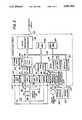
- FIG. 2is a schematic diagram showing the electrical connections between the acquisition circuit, the analysis circuit, the driver circuit and the other electrical components of the apparatus.
- FIG. 3is a schematic diagram of the acquisition circuit.
- FIG. 4is a schematic diagram of the analysis circuit.
- FIG. 5is a schematic diagram of the driver circuit.
- FIG. 6is a perspective view of the coin receiving portion of sensing apparatus in accordance with another illustrative embodiment of the invention.
- the apparatusincludes a coin hopper 10 in position to receive successive groups of coins corresponding to the correct fare from a motorist, for example.
- a motor driven wheel 13is disposed adjacent the lower portion of the hopper 10.
- the wheel 13serves to separate each group of deposited coins and to deliver the coins in each group one by one to a transporter in the form of an inclined coin track 15.
- the track 15defines a feed path for the coins, and each successive coin remains continuously in motion as it moves along the track.
- the trackadvantageously is fabricated from a nonmagnetic material such as polycarbonate or plexiglass, for example.
- the sizing station 18includes a drag arm 20 which is deflected by the periphery of the coin to pivot a shaft 21 in a counterclockwise direction as viewed in FIG. 1, to an extent proportional to the coin's diameter.
- the shaft 21is connected to a shaft encoder circuit 25 by an amplifying gear train shown schematically by the broken line 27.
- the circuit 25produces a denomination output signal corresponding to the diameter of the coin as it moves along the coin track 15.
- each successive coincontinues its movement along the coin track 15, it passes an optical detector 28.
- a photoelectric cell within the detector 28produces an output signal which is directed to an optical sensor circuit 30 by a cable 31.
- the circuit 30activates a transformer 32 which is disposed along the coin track 15 immediately adjacent the detector 28, and the voltages from the primary and secondary windings of the transformer 32 are transmitted over a cable 33 to an analog sensor 35.
- the primary windingis positioned on one side of the coin path, while the secondary winding is on the opposite side.
- the detected voltages from these windingsproduce a phase and amplitude displacement output signal corresponding to the metal content of the moving coin.
- the hoppers 40 and 41are disposed in succession along the coin feed path and are connected by respective leads 42 and 43 to an escrow circuit 45.
- the coins in a given groupremain in the uppermost hopper 40 until a validation signal is received from the circuit 45 over the lead 42, at which time the group of coins is deposited in the lowermost hopper 41.
- the circuit 45activates the discharge of the group in the hopper 41 into a storage vault 47.
- the hoppers 40 and 41are arranged such that their contents may be readily viewed by personnel monitoring the system.
- the separator wheel 13operates under the control of a motor shown schematically at 50.
- the motor 50is provided with a power supply cable 52 and a second cable 53 leading to a rotor sensor circuit 55.
- the circuit 55produces output signals corresponding to the speed of the motor and the angular position of the motor's output shaft.
- the shaft encoder 25, the optical sensor 30, the analog sensor 35 and the rotor sensor 55are connected to an acquisition circuit 60 by respective cables 61, 62, 63 and 64.
- the acquisition circuit 60receives the various output signals from these cables and converts the signals into corresponding standardized signals.
- the resulting standardized signalsare transmitted to an analysis circuit 65 over a cable 66.
- the circuits 60 and 65are supplied with power from a power supply 70 over leads 72 and 73, respectively, and a lead 74 from the power supply similarly furnishes power to a driver circuit 75.
- the driver circuit 75operates under the control of the analysis circuit 65 and is connected thereto by a cable 77. Output signals from the driver circuit are transmitted to the motor 50 over the lead 52 and to the escrow circuit 45 over a lead 78.
- the acquisition circuit 60comprises a microprocessor based interrogator of the system's sensors.
- the data collected from the various sensorsis manipulated and normalized into a standard format to provide efficient real time transfer of coin parameters to the analysis circuit 65.
- shaft home position and relative offset signals generated by the shaft encoder 25are transmitted over the lead 61 to a relative-to-absolute decoder 80.
- the decoder 80converts the incoming signals to a signal corresponding to the diameter of the coin under test, and this signal is supplied over a lead 82 to a quadrature decoder 83.
- the decoder 83drives a twelve bit magnitude register to digitize the coin diameter signal and supply the digitized signal to a microprocessor bus system 84 leading to a microprocessor controller 85.
- the bus systemincludes an eight bit high speed CMOS address mapped microprocessor with up to 16K words of both RAM and ROM, as indicated by the read-only-memory circuit 86 and the random-access-memory circuit 87.
- the phase and amplitude displacement signal from the analog sensor 35is generated by the primary winding 88 and the secondary winding 89 of the transformer 32.
- the primary winding 88is connected across leads 92 and 93. These leads in turn are connected to a precision sine wave generator 95 which is supplied with power from a lead 97 connected to a reference power regulator 98.
- the generator 95 and the regulator 98serve as a precision constant current source for the primary winding.
- the signal at the primary winding 88is detected by a buffer amplifier 100 and is then supplied over a lead 102 to a relative phase angle and amplitude detector 103.
- the signal at the secondary winding 89is supplied over leads 105 and 106 and branch leads 107 and 108 to an amplifier 110 and then over a lead 111 to the phase angle and amplitude detector 103.
- the detector 103compares the phase and amplitude deviation between the reference coil driver signal on the primary winding and the resultant coil output signal on the secondary winding and produces a digitized output signal which is supplied to the bus system 84.
- the amplitude of the signal across the secondary winding 89is transmitted over the leads 105 and 106 to a precision gain amplifier 112, then over a lead 113 to an AC to DC root mean square converter 115 and then over a lead 116 to an eight bit analog-to-digital converter 118.
- the amplifier 112amplifies and buffers the signal, and the converter 115 produces the resulting DC equivalent which is digitized by the converter 118.
- Poweris supplied to the converter 118 by a lead 120 connected to the power regulator 98, and to compensate for any temperature or power supply induced drift, the converter is connected in a ratiomatic configuration.
- the digital output signal from the converter 118is supplied to the microprocessor bus system 84.
- the quiescent phase and amplitude relationship, primary to secondary, as detected by the phase angle and amplitude detector 103, and the secondary voltage signal from the converter 118will change as a function of the metal content of the coins being tested.
- An analog comparator and detector 122is utilized to interface the optical coin sensor 30 with a microprocessor bus interface 125 leading to the bus system 84.
- the sensor 30is adjustable to provide for variations in sensor assembly tolerances.
- the rotor sensor 55produces output signals corresponding to the speed of the motor 50 (FIG. 1) and the angular position of the motor's output shaft. These signals are transmitted over the cable 64 to an analog comparator 132 in the acquisition circuit 60.
- the comparator 132serves as an interface between the rotor sensor 55 and the microprocessor bus system 84 leading to the memory circuits 86 and 87 and the microprocessor controller 85.
- the acquisition circuit 60monitors the sensors for changes in operating parameters which may indicate a failure in a portion of the system. By comparing operating speed and the normal base line data from each sensor, problems are reported to the analysis circuit 65 over the cable 66. As an illustration, should erroneous readings be detected from the analog sensor 35 the acquisition circuit warns the analysis circuit that the analog data is invalid. The system then switches to a degraded state of operation in which coin collection continues but is monitored only by sizing data from the shaft encoder 25. The circuit 65 also generates a warning message to maintenance personnel so that the necessary repairs can be made.
- the analysis circuit 65is illustrated in more detail in FIG. 4.
- the circuit 65comprises a microprocessor based evaluator of the coin data received from the acquisition circuit 60, and it includes various nonvolatile memories for storing coin parameters, fare rates and other data.
- the incoming signals from the acquisition circuit 60are received at a serial communications port 133 and are transmitted by a cable 134 to an asynchronous communications interface adaptor 135.
- the adaptor 135in turn supplies the signals to a bus system 136 and then to a read-only-memory 138, a random access memory 139 and a nonvolatile random access memory 140.
- the bus system 136is connected to a microprocessor unit 142 and to a triple programmable timer 144.
- the memory circuits 138, 139 and 140are programmed to store valid data window values for all coins entered as acceptable payment as well as additional data representing fare rates, acceptable operating parameters, etc., while the timer 144 provides operational timing for the circuit.
- the incoming data at the serial communications port 133includes data representing the diameter and metal content of each successive coin as it moves along the coin track 15 (FIG. 1).
- the diameter and metal content datais compared with the stored valid data window values, and if the incoming data falls within the window of acceptable values for a particular coin (or token) the coin is assumed to be the coin listed in that entry.
- the values of the accepted coins for each paymentare totalized, and upon receipt of a full fare the microprocessor unit 142 transmits an output signal over the bus system 136 to two asynchronous communications interface adapters 147 and 148 and a data latch circuit 150.
- the adaptor 147is connected by a cable 152 to a current loop converter 153, and a cable 154 serves to connect the converter 153 to a host and diagnostic port 155.
- the adaptor 148is connected by a cable 158 to a RS-232 converter 159 leading over a cable 160 to the port 155.
- the port 155in turn is connected to a standard host system (not shown) to indicate that the correct fare has been paid and to transmit machine status and miscellaneous house keeping data.
- the port 155may be employed as a diagnostic communications link to calibrate, test and monitor the various operating parameters and to input coin tables and fare rates.
- the correct fare signals received by the data latch circuit 150are transmitted over a cable 161 to a dual timer circuit 162.
- the circuit 162includes two one-shot timers which alternately transmit the incoming signals over leads in a cable 163 to an output port 165.
- the port 165is connected by the cable 7 (FIG. 2) to the driver circuit 75.
- the microprocessor unit 142is provided with an address decoding logic circuit 167 and a memory R/W logic circuit 168 which are connected to the unit by the bus system 136. Timing information is supplied to the interface adapters 135, 147 and 148 by a Baud rate generator 170 over a cable 172. Power is supplied to the analysis circuit from the power supply 70 (FIG. 2) and the lead 73 to a power input port 175. A cable 176 connects the port 175 to a data buffer circuit 177 leading to the bus system 136.
- poweralso is supplied from the power supply 70 to the driver circuit 75.
- the driver circuit 75serves to convert the control signals from the output port 165 of the analysis circuit 65 into levels capable of driving the electro-mechanical elements of the apparatus.
- a solid state relay 180(FIG. 5) is energized to supply AC power over the lead 52 to the motor 50 (FIG. 1).
- the motor 50drives the separator wheel 13 preparatory to the discharge of the next group of coins into the hopper 10 and then in succession into the coin track 15.
- power to the motoris interrupted to arrest the wheel 13 and thus prevent the transfer of a succeeding group of coins into the coin track.
- the validation signal from the analysis circuitalso energizes a solid state relay 183 in the driver circuit 75 to supply AC power over a lead 184 to an AC-DC converter 185.
- the DC output from the converter 185is transmitted over a lead 186 to a solenoid within the escrow circuit 45. Upon energization of this solenoid, the coins within the upper hopper 40 are discharged into the lower hopper 41 where they continue to be available for inspection by personnel monitoring the system.
- the validation signal from the analysis circuitalso is received by a solid state relay 188 to thereby energize the solid state relay and transmit AC power over a lead 189 to an AC-DC converter 190.
- the DC output from the converter 190is applied over a lead 191 to energize a second solenoid in the escrow circuit 45 and thereby discharge the preceding group of coins from the hopper 41 into the vault 47.
- the hoppers 40 and 41are readily accessible to monitoring personnel, and in the event of the absence of a proper validation signal or other discrepancy their contents may be cross-checked visually prior to the time the coins enter the vault.
- the apparatusincludes a coin track 200 which defines a feed path for groups of coins, such as the coin 202, as they move in succession from right to left along the track.
- each successive coinremains continuously in motion during its movement, and the track 200 is constructed from a nonmagnetic transparent material such as polycarbonate or plexiglass.
- the coinsare received from a hopper such as the hopper 10 shown in FIG. 1, and upon leaving the coin track they enter the successive hoppers 40 and 41 and are then discharged into the storage vault 47.
- each coinShortly after each coin enters the coin track 200, it passes an optical sensing station which includes three optical sensors 205, 206 and 207. These sensors perform a function similar to that of the optical detector 28 in the FIG. 1 embodiment and are connected to the optical sensor circuit 30 to alert the system that the coin is entering the coin analysis section of the feed path.
- the cointhen proceeds past a transformer 210 having a primary winding 211 and a secondary winding 212 disposed on opposite sides of the path.
- the quiescent phase and amplitude relationship between these windings, and the voltage on the secondary windingchange as a function of the metal content of the coin as it interrupts the magnetic field between the windings.
- the phase and amplitude relationship and voltageare used to determine the coin's metal content in the manner described heretofore.
- the leading edge of the coininterrupts an optical sensor 215 to start two independent clocks.
- the first clockruns as long as the coin is interrupting the sensor 215 to produce a count proportional to the period of time needed for the coin to pass the sensor.
- the second clockruns until the leading edge of the coin interrupts an optical sensor 216, at which time the count of the second clock is terminated to produce a count proportional to the period of time required for the coin to move from the sensor 215 to the sensor 216.
- the clock counts from the first clockare divided by the clock counts from the second clock to provide a signal equal to the diameter of the coin. This signal is supplied over the cable 61 (FIG. 2) to the acquisition circuit 60 and is processed by the acquisition circuit and the analysis circuit 65 to facilitate a determination as to the validity of the coin.
Landscapes
- Physics & Mathematics (AREA)
- General Physics & Mathematics (AREA)
- Testing Of Coins (AREA)
Abstract
Description
Claims (14)
Priority Applications (1)
| Application Number | Priority Date | Filing Date | Title |
|---|---|---|---|
| US07/491,245US5097934A (en) | 1990-03-09 | 1990-03-09 | Coin sensing apparatus |
Applications Claiming Priority (1)
| Application Number | Priority Date | Filing Date | Title |
|---|---|---|---|
| US07/491,245US5097934A (en) | 1990-03-09 | 1990-03-09 | Coin sensing apparatus |
Publications (1)
| Publication Number | Publication Date |
|---|---|
| US5097934Atrue US5097934A (en) | 1992-03-24 |
Family
ID=23951371
Family Applications (1)
| Application Number | Title | Priority Date | Filing Date |
|---|---|---|---|
| US07/491,245Expired - Fee RelatedUS5097934A (en) | 1990-03-09 | 1990-03-09 | Coin sensing apparatus |
Country Status (1)
| Country | Link |
|---|---|
| US (1) | US5097934A (en) |
Cited By (18)
| Publication number | Priority date | Publication date | Assignee | Title |
|---|---|---|---|---|
| US5407049A (en)* | 1993-07-28 | 1995-04-18 | Vincent G. Yost | Electronic parking meter and system |
| US5460256A (en)* | 1994-03-31 | 1995-10-24 | Coin Acceptors, Inc. | Coin sensor device |
| FR2722019A1 (en)* | 1994-07-01 | 1996-01-05 | Atoll Technology | Temporary storage appts. for continuous coin collection at paying point e.g. toll-gate |
| US5570771A (en)* | 1993-07-28 | 1996-11-05 | Vincent G. Yost | Electronic parking meter and system |
| US5642119A (en)* | 1993-07-28 | 1997-06-24 | Intelligent Devices, Inc. | Electronic parking meter and system |
| WO1997023849A1 (en)* | 1994-07-01 | 1997-07-03 | Atoll Technology | Buffer container with lock chamber |
| US5673781A (en)* | 1995-11-21 | 1997-10-07 | Coin Acceptors, Inc. | Coin detection device and associated method |
| GB2312070A (en)* | 1996-04-12 | 1997-10-15 | Asahi Seiko Co Ltd | Apparatus for monitoring the diameter of a disk-shaped body |
| US5852411A (en)* | 1996-07-19 | 1998-12-22 | Intelligent Devices, Inc. | Universal adaptor for electronic parking meters |
| WO1999000776A1 (en)* | 1997-06-27 | 1999-01-07 | Coinstar, Inc. | Coin bin with locking lid |
| US5992603A (en)* | 1997-12-18 | 1999-11-30 | Ginsan Industries Inc | Coin acceptance mechanism and method of determining an acceptable coin |
| WO2000017828A1 (en)* | 1997-06-27 | 2000-03-30 | Coinstar, Inc. | Coin bin with locking lid |
| US6195015B1 (en) | 1996-07-19 | 2001-02-27 | Intelligent Devices, Inc. | Electronic parking meter |
| US6599180B2 (en)* | 2001-04-05 | 2003-07-29 | Asahi Seiko Usa Inc. | Anti-theft coin monitoring sensor unit for a coin hopper dispenser |
| US20040055902A1 (en)* | 2002-09-20 | 2004-03-25 | Peklo John C | Removable coin bin |
| US20050067305A1 (en)* | 2002-09-20 | 2005-03-31 | Bochonok Steve T. | Removable coin bin |
| US9022841B2 (en) | 2013-05-08 | 2015-05-05 | Outerwall Inc. | Coin counting and/or sorting machines and associated systems and methods |
| US9036890B2 (en) | 2012-06-05 | 2015-05-19 | Outerwall Inc. | Optical coin discrimination systems and methods for use with consumer-operated kiosks and the like |
Citations (35)
| Publication number | Priority date | Publication date | Assignee | Title |
|---|---|---|---|---|
| US2950799A (en)* | 1952-02-07 | 1960-08-30 | Alan Foster | Apparatus for identifying paper money, or the like, as genuine, and for making change or the like |
| US3481443A (en)* | 1967-01-20 | 1969-12-02 | Autelca Ag | Coin checking device |
| US3680566A (en)* | 1969-09-22 | 1972-08-01 | Micro Magnetic Ind Inc | Bulk coin dispenser |
| US3869663A (en)* | 1971-06-11 | 1975-03-04 | Berliner Maschinenbau Ag | Method and apparatus for checking metallic objects by monitoring its effect on one cycle of an alternating field |
| US3901368A (en)* | 1974-03-11 | 1975-08-26 | Lance T Klinger | Coin acceptor/rejector |
| US3966034A (en)* | 1972-10-12 | 1976-06-29 | Mars, Inc. | Phase sensitive coin discrimination method and apparatus |
| US4059122A (en)* | 1973-02-10 | 1977-11-22 | Glory Kogyo Kabushiki Kaisha | Coin classifying and counting machine |
| US4086527A (en)* | 1975-03-25 | 1978-04-25 | Crouzet | Method and apparatus for monetary articles authentification |
| US4108296A (en)* | 1976-04-08 | 1978-08-22 | Nippon Coinco Co., Ltd. | Coin receiving apparatus for a vending machine |
| US4128158A (en)* | 1976-07-22 | 1978-12-05 | Coin Cop Co. | Precision coin analyzer for numismatic application |
| US4184366A (en)* | 1976-06-08 | 1980-01-22 | Butler Frederick R | Coin testing apparatus |
| US4234071A (en)* | 1977-11-03 | 1980-11-18 | Compagnie De Signaux Et D'enterprises Electriques | Device for checking metal pieces, particularly coins |
| US4254857A (en)* | 1978-09-15 | 1981-03-10 | H. R. Electronics Company | Detection device |
| US4275806A (en)* | 1977-06-07 | 1981-06-30 | Fuji Electric Co., Ltd. | Coin sorting machine |
| US4334604A (en)* | 1979-03-15 | 1982-06-15 | Casino Investment Limited | Coin detecting apparatus for distinguishing genuine coins from slugs, spurious coins and the like |
| US4349095A (en)* | 1977-02-19 | 1982-09-14 | P A Management Consultants Limited | Coin discriminating apparatus |
| US4361218A (en)* | 1979-03-30 | 1982-11-30 | Mars, Incorporated | Coin testing apparatus |
| US4398626A (en)* | 1981-08-21 | 1983-08-16 | Mars, Inc. | Low frequency phase shift coin examination method and apparatus |
| US4431014A (en)* | 1981-02-10 | 1984-02-14 | Fuji Electric Co., Ltd. | Coin sorting machine |
| US4460080A (en)* | 1981-03-19 | 1984-07-17 | Aeronautical & General Instruments Limited | Coin validation apparatus |
| US4460003A (en)* | 1981-08-21 | 1984-07-17 | Mars, Inc. | Coin presence sensing apparatus |
| US4462513A (en)* | 1980-02-06 | 1984-07-31 | Mars, Inc. | Testing coins |
| US4471864A (en)* | 1980-03-06 | 1984-09-18 | Duane Marshall | Slug rejector |
| US4474281A (en)* | 1982-06-07 | 1984-10-02 | General Signal Corporation | Apparatus and method for coin diameter computation |
| US4493411A (en)* | 1982-09-29 | 1985-01-15 | Mars, Inc. | Self tuning low frequency phase shift coin examination method and apparatus |
| US4509633A (en)* | 1983-08-24 | 1985-04-09 | Reed Industries, Inc. | Electronic coin validator with improved diameter sensing apparatus |
| US4538719A (en)* | 1983-07-01 | 1985-09-03 | Hilgraeve, Incorporated | Electronic coin acceptor |
| US4572349A (en)* | 1982-12-16 | 1986-02-25 | Laurel Bank Machine Co., Ltd. | Coin checking device for use in a coin handling machine |
| US4625852A (en)* | 1985-09-05 | 1986-12-02 | Coil Acceptors, Inc. | Coin detection and validation means and method |
| US4646904A (en)* | 1985-09-05 | 1987-03-03 | Coin Acceptors, Inc. | Coin sizing means and method |
| US4666027A (en)* | 1986-02-07 | 1987-05-19 | Validation Systems, Inc. | Coin validation apparatus and method for detecting stringing of coins and distinguishing valid tokens or coins from slugs |
| US4705154A (en)* | 1985-05-17 | 1987-11-10 | Matsushita Electric Industrial Co. Ltd. | Coin selection apparatus |
| US4749074A (en)* | 1985-10-11 | 1988-06-07 | Matsushita Electric Industrial Co., Ltd. | Coin sorting apparatus with reference value correction system |
| US4845994A (en)* | 1988-02-29 | 1989-07-11 | Automatic Toll Systems, Inc. | Coin testing apparatus |
| US4846332A (en)* | 1988-02-29 | 1989-07-11 | Automatic Toll Systems, Inc. | Counterfeit coin detector circuit |
- 1990
- 1990-03-09USUS07/491,245patent/US5097934A/ennot_activeExpired - Fee Related
Patent Citations (35)
| Publication number | Priority date | Publication date | Assignee | Title |
|---|---|---|---|---|
| US2950799A (en)* | 1952-02-07 | 1960-08-30 | Alan Foster | Apparatus for identifying paper money, or the like, as genuine, and for making change or the like |
| US3481443A (en)* | 1967-01-20 | 1969-12-02 | Autelca Ag | Coin checking device |
| US3680566A (en)* | 1969-09-22 | 1972-08-01 | Micro Magnetic Ind Inc | Bulk coin dispenser |
| US3869663A (en)* | 1971-06-11 | 1975-03-04 | Berliner Maschinenbau Ag | Method and apparatus for checking metallic objects by monitoring its effect on one cycle of an alternating field |
| US3966034A (en)* | 1972-10-12 | 1976-06-29 | Mars, Inc. | Phase sensitive coin discrimination method and apparatus |
| US4059122A (en)* | 1973-02-10 | 1977-11-22 | Glory Kogyo Kabushiki Kaisha | Coin classifying and counting machine |
| US3901368A (en)* | 1974-03-11 | 1975-08-26 | Lance T Klinger | Coin acceptor/rejector |
| US4086527A (en)* | 1975-03-25 | 1978-04-25 | Crouzet | Method and apparatus for monetary articles authentification |
| US4108296A (en)* | 1976-04-08 | 1978-08-22 | Nippon Coinco Co., Ltd. | Coin receiving apparatus for a vending machine |
| US4184366A (en)* | 1976-06-08 | 1980-01-22 | Butler Frederick R | Coin testing apparatus |
| US4128158A (en)* | 1976-07-22 | 1978-12-05 | Coin Cop Co. | Precision coin analyzer for numismatic application |
| US4349095A (en)* | 1977-02-19 | 1982-09-14 | P A Management Consultants Limited | Coin discriminating apparatus |
| US4275806A (en)* | 1977-06-07 | 1981-06-30 | Fuji Electric Co., Ltd. | Coin sorting machine |
| US4234071A (en)* | 1977-11-03 | 1980-11-18 | Compagnie De Signaux Et D'enterprises Electriques | Device for checking metal pieces, particularly coins |
| US4254857A (en)* | 1978-09-15 | 1981-03-10 | H. R. Electronics Company | Detection device |
| US4334604A (en)* | 1979-03-15 | 1982-06-15 | Casino Investment Limited | Coin detecting apparatus for distinguishing genuine coins from slugs, spurious coins and the like |
| US4361218A (en)* | 1979-03-30 | 1982-11-30 | Mars, Incorporated | Coin testing apparatus |
| US4462513A (en)* | 1980-02-06 | 1984-07-31 | Mars, Inc. | Testing coins |
| US4471864A (en)* | 1980-03-06 | 1984-09-18 | Duane Marshall | Slug rejector |
| US4431014A (en)* | 1981-02-10 | 1984-02-14 | Fuji Electric Co., Ltd. | Coin sorting machine |
| US4460080A (en)* | 1981-03-19 | 1984-07-17 | Aeronautical & General Instruments Limited | Coin validation apparatus |
| US4460003A (en)* | 1981-08-21 | 1984-07-17 | Mars, Inc. | Coin presence sensing apparatus |
| US4398626A (en)* | 1981-08-21 | 1983-08-16 | Mars, Inc. | Low frequency phase shift coin examination method and apparatus |
| US4474281A (en)* | 1982-06-07 | 1984-10-02 | General Signal Corporation | Apparatus and method for coin diameter computation |
| US4493411A (en)* | 1982-09-29 | 1985-01-15 | Mars, Inc. | Self tuning low frequency phase shift coin examination method and apparatus |
| US4572349A (en)* | 1982-12-16 | 1986-02-25 | Laurel Bank Machine Co., Ltd. | Coin checking device for use in a coin handling machine |
| US4538719A (en)* | 1983-07-01 | 1985-09-03 | Hilgraeve, Incorporated | Electronic coin acceptor |
| US4509633A (en)* | 1983-08-24 | 1985-04-09 | Reed Industries, Inc. | Electronic coin validator with improved diameter sensing apparatus |
| US4705154A (en)* | 1985-05-17 | 1987-11-10 | Matsushita Electric Industrial Co. Ltd. | Coin selection apparatus |
| US4625852A (en)* | 1985-09-05 | 1986-12-02 | Coil Acceptors, Inc. | Coin detection and validation means and method |
| US4646904A (en)* | 1985-09-05 | 1987-03-03 | Coin Acceptors, Inc. | Coin sizing means and method |
| US4749074A (en)* | 1985-10-11 | 1988-06-07 | Matsushita Electric Industrial Co., Ltd. | Coin sorting apparatus with reference value correction system |
| US4666027A (en)* | 1986-02-07 | 1987-05-19 | Validation Systems, Inc. | Coin validation apparatus and method for detecting stringing of coins and distinguishing valid tokens or coins from slugs |
| US4845994A (en)* | 1988-02-29 | 1989-07-11 | Automatic Toll Systems, Inc. | Coin testing apparatus |
| US4846332A (en)* | 1988-02-29 | 1989-07-11 | Automatic Toll Systems, Inc. | Counterfeit coin detector circuit |
Non-Patent Citations (5)
| Title |
|---|
| Analog Devices AD 536A; undated.* |
| Analog Devices AD1170; Sep. 1986.* |
| Analog Devices AD521, undated.* |
| Hewlett Packard HCTL 2000; Jan. 1986.* |
| Hewlett Packard HCTL-2000; Jan. 1986. |
Cited By (29)
| Publication number | Priority date | Publication date | Assignee | Title |
|---|---|---|---|---|
| US5570771A (en)* | 1993-07-28 | 1996-11-05 | Vincent G. Yost | Electronic parking meter and system |
| US5642119A (en)* | 1993-07-28 | 1997-06-24 | Intelligent Devices, Inc. | Electronic parking meter and system |
| US5407049A (en)* | 1993-07-28 | 1995-04-18 | Vincent G. Yost | Electronic parking meter and system |
| US5460256A (en)* | 1994-03-31 | 1995-10-24 | Coin Acceptors, Inc. | Coin sensor device |
| FR2722019A1 (en)* | 1994-07-01 | 1996-01-05 | Atoll Technology | Temporary storage appts. for continuous coin collection at paying point e.g. toll-gate |
| WO1997023849A1 (en)* | 1994-07-01 | 1997-07-03 | Atoll Technology | Buffer container with lock chamber |
| US5673781A (en)* | 1995-11-21 | 1997-10-07 | Coin Acceptors, Inc. | Coin detection device and associated method |
| US5950796A (en)* | 1996-04-12 | 1999-09-14 | Asahi Seiko Kabushiki Kaisha | Apparatus for measuring a diameter of a disk body |
| GB2312070A (en)* | 1996-04-12 | 1997-10-15 | Asahi Seiko Co Ltd | Apparatus for monitoring the diameter of a disk-shaped body |
| GB2312070B (en)* | 1996-04-12 | 1999-10-13 | Asahi Seiko Co Ltd | Disc ejection apparatus for monitoring the diameter of a disk-shaped body |
| US6078272A (en)* | 1996-07-19 | 2000-06-20 | Intelligent Devices, Inc. | Universal adaptor for electronic parking meters |
| US5852411A (en)* | 1996-07-19 | 1998-12-22 | Intelligent Devices, Inc. | Universal adaptor for electronic parking meters |
| US6195015B1 (en) | 1996-07-19 | 2001-02-27 | Intelligent Devices, Inc. | Electronic parking meter |
| US6275170B1 (en) | 1996-07-19 | 2001-08-14 | Intelligent Devices, Inc. | Universal adaptor for electronic parking meters |
| WO1999000776A1 (en)* | 1997-06-27 | 1999-01-07 | Coinstar, Inc. | Coin bin with locking lid |
| WO2000017828A1 (en)* | 1997-06-27 | 2000-03-30 | Coinstar, Inc. | Coin bin with locking lid |
| US6082519A (en)* | 1997-06-27 | 2000-07-04 | Coinstar, Inc. | Coin bin with locking lid |
| US5992603A (en)* | 1997-12-18 | 1999-11-30 | Ginsan Industries Inc | Coin acceptance mechanism and method of determining an acceptable coin |
| US6599180B2 (en)* | 2001-04-05 | 2003-07-29 | Asahi Seiko Usa Inc. | Anti-theft coin monitoring sensor unit for a coin hopper dispenser |
| US20040055902A1 (en)* | 2002-09-20 | 2004-03-25 | Peklo John C | Removable coin bin |
| US6854640B2 (en) | 2002-09-20 | 2005-02-15 | Cummins-Allison Corp. | Removable coin bin |
| US20050067305A1 (en)* | 2002-09-20 | 2005-03-31 | Bochonok Steve T. | Removable coin bin |
| US20050087425A1 (en)* | 2002-09-20 | 2005-04-28 | Peklo John C. | Removable coin bin |
| US20070108015A1 (en)* | 2002-09-20 | 2007-05-17 | Bochonok Steve T | Removable coin bin |
| US7243773B2 (en) | 2002-09-20 | 2007-07-17 | Cummins-Allison Corp. | Removable coin bin |
| US7337890B2 (en) | 2002-09-20 | 2008-03-04 | Cummins-Allison Corp. | Removable coin bin |
| US9036890B2 (en) | 2012-06-05 | 2015-05-19 | Outerwall Inc. | Optical coin discrimination systems and methods for use with consumer-operated kiosks and the like |
| US9594982B2 (en) | 2012-06-05 | 2017-03-14 | Coinstar, Llc | Optical coin discrimination systems and methods for use with consumer-operated kiosks and the like |
| US9022841B2 (en) | 2013-05-08 | 2015-05-05 | Outerwall Inc. | Coin counting and/or sorting machines and associated systems and methods |
Similar Documents
| Publication | Publication Date | Title |
|---|---|---|
| US5097934A (en) | Coin sensing apparatus | |
| JP2534802B2 (en) | Methods for currency recognition | |
| EP0101276B1 (en) | Method of and apparatus for discriminating coins or bank notes | |
| US5535127A (en) | Processing apparatus for mail with stamps | |
| US4283708A (en) | Paper currency acceptor | |
| US5174562A (en) | Paper sheet handling apparatus | |
| US5533627A (en) | Device for feeding and storing valuable documents | |
| AU550975B2 (en) | Programmable vending machine accountability apparatus | |
| US20020008138A1 (en) | Sheet processing apparatus and method for close examining sheets in the same, and transaction apparatus | |
| HK166396A (en) | Monitoring sheet length | |
| PT1669935E (en) | Method for automatically recording the use of fee-based vehicles and for deducting the fees | |
| NO304536B1 (en) | Self-controlled pulse reading and recording system | |
| US3754558A (en) | Coin processing apparatus with jam detection system | |
| CN104574646A (en) | Detecting and locating method of blocked money in ATM | |
| US6198788B1 (en) | Encoder test apparatus and method | |
| US6109416A (en) | Method of operating a bill and coin changer | |
| CN1379369A (en) | Automatic booking machine | |
| JP3382009B2 (en) | Paper processing equipment | |
| JP3732647B2 (en) | Automatic cash deposit / withdrawal device | |
| JPH06503191A (en) | coin mechanism | |
| JPH0219887Y2 (en) | ||
| KR880000187B1 (en) | Banknote Identification Device | |
| KR880001242B1 (en) | Banknote discriminator | |
| JPS6243422Y2 (en) | ||
| JPS6056749A (en) | Recovery device of abnormally fed bill |
Legal Events
| Date | Code | Title | Description |
|---|---|---|---|
| AS | Assignment | Owner name:AUTOMATIC TOIL SYSTEMS, INC., NEW JERSEY Free format text:ASSIGNMENT OF ASSIGNORS INTEREST.;ASSIGNOR:QUINLAN, THOMAS J. JR.;REEL/FRAME:005257/0168 Effective date:19900306 | |
| CC | Certificate of correction | ||
| FEPP | Fee payment procedure | Free format text:PAYOR NUMBER ASSIGNED (ORIGINAL EVENT CODE: ASPN); ENTITY STATUS OF PATENT OWNER: LARGE ENTITY | |
| FPAY | Fee payment | Year of fee payment:4 | |
| AS | Assignment | Owner name:CUBIC TOLL SYSTEMS, INC., CALIFORNIA Free format text:CHANGE OF NAME;ASSIGNOR:AUTOMATIC TOLL SYSTEMS, INC.;REEL/FRAME:008268/0024 Effective date:19910313 | |
| AS | Assignment | Owner name:SYNTONIC TECHNOLOGY, INC., CALIFORNIA Free format text:MERGER;ASSIGNOR:CUBIC TOLL SYSTEMS, INC.;REEL/FRAME:010175/0509 Effective date:19960604 Owner name:SYNTONIC TECHNOLOGY, INC., A DELAWARE CORPORATION, Free format text:MERGER;ASSIGNOR:CUBIC TOLL SYSTEMS, INC., A NEW YORK CORPORATION;REEL/FRAME:010180/0481 Effective date:19971027 | |
| AS | Assignment | Owner name:DEUTSCHE FINANCIAL SERVICES CORPORATION, GEORGIA Free format text:SECURITY INTEREST;ASSIGNORS:TRANSCORE HOLDING, INC.;SYNTONIC TECHNOLOGY, INC.;JHK & ASSOCIATES, INC.;REEL/FRAME:010247/0458 Effective date:19990903 | |
| REMI | Maintenance fee reminder mailed | ||
| LAPS | Lapse for failure to pay maintenance fees | ||
| FP | Lapsed due to failure to pay maintenance fee | Effective date:20000324 | |
| AS | Assignment | Owner name:SYNTONIC TECHNOLOGY, INC., PENNSYLVANIA Free format text:RELEASE BY SECURED PARTY;ASSIGNOR:DEUTSCHE FINANCIAL SERVICES CORPORATION;REEL/FRAME:011058/0408 Effective date:20000627 | |
| AS | Assignment | Owner name:DEUTSCHE FINANCIAL SERVICES CORPORATION, ILLINOIS Free format text:SECURITY INTEREST;ASSIGNOR:SYNTONIC TECHNOLOGY, INC.;REEL/FRAME:011295/0195 Effective date:20000630 | |
| AS | Assignment | Owner name:HARRIS TRUST & SAVINGS BANK, AS AGENT, ILLINOIS Free format text:SECOND AMENDED & RESTATED CONDITIONAL ASSIGNMENT & PATENT SECURITY AGREEMENT;ASSIGNOR:TRANSCORE, INC.;REEL/FRAME:011648/0129 Effective date:20010205 | |
| AS | Assignment | Owner name:TRANSCORE, INC., PENNSYLVANIA Free format text:CHANGE OF NAME;ASSIGNOR:SYNTONIC TECHNOLOGY, INC.;REEL/FRAME:011934/0406 Effective date:19991115 | |
| AS | Assignment | Owner name:TRANSCORE, LP, PENNSYLVANIA Free format text:CHANGE OF ENTITY TYPE;ASSIGNOR:TRANSCORE, INC.;REEL/FRAME:012166/0754 Effective date:20010910 | |
| AS | Assignment | Owner name:TC (BERMUDA) FINANCE, LTD., BERMUDA Free format text:ASSIGNMENT OF ASSIGNORS INTEREST;ASSIGNOR:TRANSCORE, L.P.;REEL/FRAME:012243/0188 Effective date:20010910 | |
| AS | Assignment | Owner name:TC (BERMUDA) LICENSE, LTD., BERMUDA Free format text:ASSIGNMENT OF ASSIGNORS INTEREST;ASSIGNOR:TC (BERMUDA) FINANCE, LTD.;REEL/FRAME:012243/0203 Effective date:20010910 | |
| AS | Assignment | Owner name:TRANSCORE, L.P., PENNSYLVANIA Free format text:RELEASEOF SECURITY INTEREST IN PATENTS;ASSIGNOR:HARRIS TRUST AND SAVINGS BANK;REEL/FRAME:012243/0883 Effective date:20010910 | |
| FEPP | Fee payment procedure | Free format text:PAYER NUMBER DE-ASSIGNED (ORIGINAL EVENT CODE: RMPN); ENTITY STATUS OF PATENT OWNER: LARGE ENTITY Free format text:PAYOR NUMBER ASSIGNED (ORIGINAL EVENT CODE: ASPN); ENTITY STATUS OF PATENT OWNER: LARGE ENTITY | |
| AS | Assignment | Owner name:HARRIS TRUST & SAVINGS BANK, AS AGENT, ILLINOIS Free format text:THIRD AMENDED AND RESTATED CONDITIONAL ASSIGNMENT & TRADEMARK SECURITY AGREEMENT;ASSIGNOR:TC (BERMUDA) LICENSE, LTD.;REEL/FRAME:012418/0262 Effective date:20010910 | |
| AS | Assignment | Owner name:TC (BERMUDA) LICENSE, LTD., BERMUDA Free format text:TERMINATION OF SECURITY INTEREST;ASSIGNOR:HARRIS TRUST AND SAVINGS BANK;REEL/FRAME:013516/0561 Effective date:20021018 | |
| AS | Assignment | Owner name:HARRIS TRUST AND SAVINGS BANK, AS AGENT, ILLINOIS Free format text:SECURITY INTEREST;ASSIGNOR:TC (BERMUDA) LICENSE, LTD.;REEL/FRAME:014119/0886 Effective date:20021018 | |
| AS | Assignment | Owner name:TC LICENSE LTD., PENNSYLVANIA Free format text:ASSIGNMENT OF ASSIGNORS INTEREST;ASSIGNOR:TC (BERMUDA) LICENSE, LTD.;REEL/FRAME:015438/0556 Effective date:20041207 Owner name:TC LICENSE LTD.,PENNSYLVANIA Free format text:ASSIGNMENT OF ASSIGNORS INTEREST;ASSIGNOR:TC (BERMUDA) LICENSE, LTD.;REEL/FRAME:015438/0556 Effective date:20041207 | |
| AS | Assignment | Owner name:TC (BERMUDA) LICENSE, LTD., VIRGINIA Free format text:TERMINATION AND RELEASE OF SECURITY INTEREST (PREVIOUSLY RECORDED AT REEL 14119 FRAME 0886);ASSIGNOR:HARRIS TRUST AND SAVINGS BANK;REEL/FRAME:015521/0010 Effective date:20041210 | |
| AS | Assignment | Owner name:JPMORGAN CHASE BANK, N.A., AS ADMINISTRATIVE AGENT Free format text:SECURITY AGREEMENT;ASSIGNOR:TC LICENSE LTD.;REEL/FRAME:015541/0098 Effective date:20041213 | |
| AS | Assignment | Owner name:TC LICENSE LTD., PENNSYLVANIA Free format text:TERMINATION AND RELEASE OF SECURITY;ASSIGNOR:JPMORGAN CHASE BANK, N.A.;REEL/FRAME:021281/0468 Effective date:20080701 Owner name:TC LICENSE LTD.,PENNSYLVANIA Free format text:TERMINATION AND RELEASE OF SECURITY;ASSIGNOR:JPMORGAN CHASE BANK, N.A.;REEL/FRAME:021281/0468 Effective date:20080701 | |
| STCH | Information on status: patent discontinuation | Free format text:PATENT EXPIRED DUE TO NONPAYMENT OF MAINTENANCE FEES UNDER 37 CFR 1.362 |