US5097861A - Irrigation method and control system - Google Patents
Irrigation method and control systemDownload PDFInfo
- Publication number
- US5097861A US5097861AUS07/241,930US24193088AUS5097861AUS 5097861 AUS5097861 AUS 5097861AUS 24193088 AUS24193088 AUS 24193088AUS 5097861 AUS5097861 AUS 5097861A
- Authority
- US
- United States
- Prior art keywords
- watering
- predetermined
- period
- location
- stations
- Prior art date
- Legal status (The legal status is an assumption and is not a legal conclusion. Google has not performed a legal analysis and makes no representation as to the accuracy of the status listed.)
- Expired - Lifetime
Links
- 230000002262irrigationEffects0.000titleclaimsdescription51
- 238000003973irrigationMethods0.000titleclaimsdescription51
- 238000000034methodMethods0.000titleclaimsdescription37
- XLYOFNOQVPJJNP-UHFFFAOYSA-NwaterSubstancesOXLYOFNOQVPJJNP-UHFFFAOYSA-N0.000claimsabstractdescription54
- 230000007613environmental effectEffects0.000claimsabstractdescription20
- 230000015654memoryEffects0.000claimsdescription21
- 239000002689soilSubstances0.000claimsdescription7
- 238000012544monitoring processMethods0.000claimsdescription3
- 230000003213activating effectEffects0.000claims13
- 230000004913activationEffects0.000claims6
- 238000001556precipitationMethods0.000abstractdescription7
- 230000009471actionEffects0.000description6
- 238000004364calculation methodMethods0.000description5
- 238000009434installationMethods0.000description5
- 238000004891communicationMethods0.000description4
- 230000006870functionEffects0.000description4
- 244000025254Cannabis sativaSpecies0.000description2
- 241000196324EmbryophytaSpecies0.000description2
- 230000008859changeEffects0.000description2
- 238000001514detection methodMethods0.000description2
- 238000010586diagramMethods0.000description2
- 230000008569processEffects0.000description2
- 238000011084recoveryMethods0.000description2
- 0*C1C(CC2)C2=CC1Chemical compound*C1C(CC2)C2=CC10.000description1
- 230000006978adaptationEffects0.000description1
- 230000004075alterationEffects0.000description1
- 238000009529body temperature measurementMethods0.000description1
- 238000010276constructionMethods0.000description1
- 238000013479data entryMethods0.000description1
- 230000001419dependent effectEffects0.000description1
- 230000000694effectsEffects0.000description1
- 238000009499grossingMethods0.000description1
- 239000004973liquid crystal related substanceSubstances0.000description1
- 239000000463materialSubstances0.000description1
- 239000011159matrix materialSubstances0.000description1
- 238000012986modificationMethods0.000description1
- 230000004048modificationEffects0.000description1
- 239000003607modifierSubstances0.000description1
- NJPPVKZQTLUDBO-UHFFFAOYSA-NnovaluronChemical compoundC1=C(Cl)C(OC(F)(F)C(OC(F)(F)F)F)=CC=C1NC(=O)NC(=O)C1=C(F)C=CC=C1FNJPPVKZQTLUDBO-UHFFFAOYSA-N0.000description1
- 230000002093peripheral effectEffects0.000description1
- 239000004033plasticSubstances0.000description1
- 229920003023plasticPolymers0.000description1
- 239000004800polyvinyl chlorideSubstances0.000description1
- 238000003825pressingMethods0.000description1
- 230000004044responseEffects0.000description1
- 230000000717retained effectEffects0.000description1
- 239000007787solidSubstances0.000description1
- 238000003860storageMethods0.000description1
- 230000036962time dependentEffects0.000description1
Images


Classifications
- G—PHYSICS
- G05—CONTROLLING; REGULATING
- G05D—SYSTEMS FOR CONTROLLING OR REGULATING NON-ELECTRIC VARIABLES
- G05D22/00—Control of humidity
- G05D22/02—Control of humidity characterised by the use of electric means
- A—HUMAN NECESSITIES
- A01—AGRICULTURE; FORESTRY; ANIMAL HUSBANDRY; HUNTING; TRAPPING; FISHING
- A01G—HORTICULTURE; CULTIVATION OF VEGETABLES, FLOWERS, RICE, FRUIT, VINES, HOPS OR SEAWEED; FORESTRY; WATERING
- A01G25/00—Watering gardens, fields, sports grounds or the like
- A01G25/16—Control of watering
- Y—GENERAL TAGGING OF NEW TECHNOLOGICAL DEVELOPMENTS; GENERAL TAGGING OF CROSS-SECTIONAL TECHNOLOGIES SPANNING OVER SEVERAL SECTIONS OF THE IPC; TECHNICAL SUBJECTS COVERED BY FORMER USPC CROSS-REFERENCE ART COLLECTIONS [XRACs] AND DIGESTS
- Y02—TECHNOLOGIES OR APPLICATIONS FOR MITIGATION OR ADAPTATION AGAINST CLIMATE CHANGE
- Y02A—TECHNOLOGIES FOR ADAPTATION TO CLIMATE CHANGE
- Y02A40/00—Adaptation technologies in agriculture, forestry, livestock or agroalimentary production
- Y02A40/10—Adaptation technologies in agriculture, forestry, livestock or agroalimentary production in agriculture
- Y02A40/22—Improving land use; Improving water use or availability; Controlling erosion
- Y—GENERAL TAGGING OF NEW TECHNOLOGICAL DEVELOPMENTS; GENERAL TAGGING OF CROSS-SECTIONAL TECHNOLOGIES SPANNING OVER SEVERAL SECTIONS OF THE IPC; TECHNICAL SUBJECTS COVERED BY FORMER USPC CROSS-REFERENCE ART COLLECTIONS [XRACs] AND DIGESTS
- Y10—TECHNICAL SUBJECTS COVERED BY FORMER USPC
- Y10T—TECHNICAL SUBJECTS COVERED BY FORMER US CLASSIFICATION
- Y10T137/00—Fluid handling
- Y10T137/1842—Ambient condition change responsive
- Y10T137/1866—For controlling soil irrigation
- Y10T137/189—Soil moisture sensing
Definitions
- the present inventionrelates to irrigation, and more particularly, to an improved irrigation method and an improved electronic irrigation control system which is easier to program and more flexible than prior irrigation control systems.
- the present inventioneliminates both the concept of user run time calculations and awkward controller entry switches.
- the usersimply enters the times when the system is not supposed to water and the control system calculates the necessary water schedule based upon parameters previously entered by the user.
- the present inventionoperates on the premise that if enough environmental and geographical data is known about the installation site, then accurate watering schedules can be calculated. Soil moisture sensors are not needed to satisfy the water requirements for most turf and plant materials.
- the usermust enter parameters which define the installation site characteristics.
- theseare entered and reviewed by a combination of a single rotary switch and liquid crystal display (LCD). No other operator entry devices are required to completely set up and use the control system. Once the system parameters are entered they become part of the permanent system data tables which are retained even if AC power is lost, without the need for user accessible batteries.
- LCDliquid crystal display
- the human interface for entering and displaying system informationis based on a graphics display and a single entry switch which is both rotated and pressed to select various items.
- the LCDpresents menus that include graphic images (ICONS) and overlaid text.
- ICONSgraphic images
- the use of both text and graphic ICONS in each menu presentationavoids confusion and clarifies the data entry and retrieval process.
- the useris presented a hierarchy of menu structures on the LCD from which he or she can completely set up, modify and interrogate the control system.
- the menu structuresare presented in a way which guides the user from the top menu through the sub-menus.
- a selection baris moved to the next highlighted menu item on the display.
- the userselects or "picks" highlighted items from the menu by pressing the entry knob.
- a cursor-barmoves across the menu from item to item in a continuous loop from left to right and top to bottom until a selection is made. If the item picked is to be changed, rotating the switch will allow the user to view the changes on the LCD display.
- pushing the switch buttonwill enter the parameters.
- One menu select item in each sub-menuhas the capability of returning to the previous menu level.
- a system status lineis reserved on most menu levels in the preferred embodiment to show current system information to the user.
- Status informationconsists of items such as: active stations, next scheduled run time, calculated length of run time, time of day, error messages, etc.
- the preferred embodiment of the control systemuses information stored in ROM data tables in conjunction with daily temperature, rainfall and variables entered by the user to calculate and manage the watering schedules.
- the stored data tablescontain information about monthly mean temperature and evapotranspiration rates (E.T.) for each section of the United States and Canada.
- the data tablesactually contain twelve values of E.T. or temperature per ZIP Code area. This data when used with the user supplied variables such as grass type, soil intake rate, station's precipitation rate and time "not to water,” is used by the control system to calculate water schedules for each output station.
- water schedule calculations in the preferred embodimentare based on stored constants in ROM tables in conjunction with user supplied variables which also become part of the permanent data base.
- the E.T. and temperature information contained in the ROM data tablesare data which has been collected by agencies like CIMIS. This E.T. and temperature data represents the "mean monthly value" for each ZIP Code in the United States (twelve values per ZIP Code).
- the "Daily Value” for E.T. or temperatureis derived from the mean monthly values by applying a "mathematical spline" or smoothing algorithm run across a previous, present and next-month basis. The resulting daily values have drastic variations and aberrations filtered out.
- the userhas the responsibility of providing the station's precipitation rate (inches per hour), soil intake (inches per hour) and the grass coefficient (multiplier factor of 0.6 to 1). This is required only once during initial installation and setup of the control system. Because of the extensive data base, the control system has the ability to react to excessive temperature changes or rainfall that may occur at the installation site.
- a user "variance" menu input itemis also provided to allow for unique plant types or special growing zones.
- the ZIP Code and each station's precipitation ratemust be entered by the user for the preferred embodiment of the control system to operate properly for the specific location at which the control system is to be used and the field water requirements. All other inputs may have default values and, if used properly, they will allow for considerable watering accuracy.
- control systemincludes a microprocessor and a time of day clock with a nonvolatile memory.
- the clock and nonvolatile memory contentsare used for almost all calculations associated with water scheduling, so these devices are periodically checked for proper operation by the operating system software.
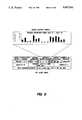
- FIG. 1is a diagrammatic view of a typical layout of lawn and garden input and output devices which may be connected to a preferred embodiment of our irrigation control system illustrated in elevation in the lower right hand corner;
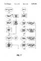
- FIG. 2is an overall block diagram of the preferred embodiment of our irrigation control system
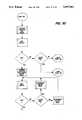
- FIG. 3illustrates examples of the initial setup and top level menus which are displayed by the preferred embodiment
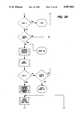
- FIG. 4illustrates examples of the station and top level menus displayed by the preferred embodiment during station editing
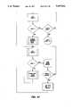
- FIG. 5illustrates examples of the manual operation and top level menus displayed by the preferred embodiment during manual operation
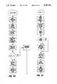
- FIG. 6illustrates examples of the water history and top level menus displayed by the preferred embodiment during station water application.
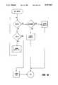
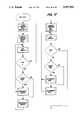
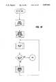
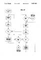
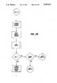
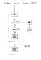
- FIGS. 7 through 53are a series of flow diagrams which together illustrate the logic performed by the preferred embodiment of our irrigation control system. Unconnected lines on individual figures connect to the corresponding unconnected lines of preceding or succeeding figures.
- FIG. 1illustrates a representative layout of a plurality of possible lawn and garden input and output devices labeled A through J surrounding a residential home 50 and detached garage 52. They may be connected to a preferred embodiment of our control system which includes a rectangular control box or panel 54 which may be mounted to a pedestal or the wall inside the garage. Standard household AC power is supplied to the control system via cable or cord 56. Communication between those of the devices A-J which are electrical and the control system is provided via dedicated wires 58 which are buried throughout the yard and extend along the wall of the garage, entering the underside of the control panel 54 via conduit 60.
- the watering portion of the output devicesmay include conventional electromechanically operated valves A which control the flow of water to sprinklers B and drip emitters C. These components are connected in the usual fashion by underground polyvinylchloride (PVC) or ABS (Trademark) plastic pipe 62 to a source of pressurized water (not illustrated).
- PVCpolyvinylchloride
- ABSTrademark
- the sprinklers Bare generally located in the lawn area 64 while the drip emitters are generally located adjacent a tree such as 66, or adjacent shrubbery or flowers, etc. (not illustrated).
- the auxiliary portion of the output devicesmay include lights D, a house alarm E, appliances F (e.g. coffee pot, stereo, etc.) and pumps G (e.g. in a fountain 68 or in a pool filter).
- the valves A, lights D, alarm E, appliances F and pumps Gmay all be activated and controlled via electrical output signals from the control system.
- the input devicesmay include a rain gauge H, a temperature gauge I, a flowmeter J, and a humidity sensor (not illustrated), all being conventional units producing electrical input signals that can be monitored by the control system. It should be understood that FIG. 1 is exemplary only that additional input and output devices may be added and configured in a variety of different ways depending upon the requirements of the location.
- the preferred embodiment of our control systemis an intelligent microprocessor based system. It includes the following components which communicate on a bi-directional system bus: a microprocessor (MPU) 70, a program and data table memory (ROM) 72, an external data memory 73 and a system data random access memory (RAM) 74.
- the systemfurther includes a special nonvolatile RAM memory 76 and a time of day clock 78.
- the MPU 70communicates in a conventional manner with the memories 72, 73, 74 and 76 and the clock 78 via address data and system buses and an address decode circuit 79.
- analog interface 80(FIG. 2) and multiplexer (MUX) 82 which are connected to an analog to digital (A/D) converter 84 via analog line 86.
- the A/D converter 84in turn communicates directly with the MPU 70.
- Valve control and error checking circuit 88is connected to the A/D converter 84, the MUX 82 and the system bus.
- a rotary switch 90enables the user to manually input commands directly to the MPU 70.
- An LCD control circuit 92is connected directly to the MPU, to the system bus and to a video RAM memory 94 for driving an LCD display 96 to visually generate the menus hereafter described.
- a typical menu depicted by LCD 96is illustrated in FIG. 1.
- the rotary switch 90(FIG. 2) includes a knob 90a (FIG. 1) mounted in front of the panel 54 below the LCD display 96 for grasping and rotation by the user's hand.
- An optional serial communications port 98(FIG. 2) is connected to the MPU 70 for communication with external devices such as a personal computer (not illustrated).
- a power supply 100is connected to the AC input power on cable 56 and drives the MPU 70 and associated devices with suitable DC voltages such as +5VDC, +12VDC and -12VDC.
- the power supply 100preferably includes a conventional power fail detection circuit that provides alarm input to the MPU.
- a power line modem 102may be connected to the MPU 70 so that it may communicate with similar systems connected to the same AC power line.
- the MPU 70may be provided by a Siemens 80535 8 bit microprocessor unit with 256 bytes of on-chip RAM, six 8-bit ports, three 16 bit timers, serial port, eight channel 8-bit analog to digital converter and a 16 bit watch dog timer.
- the 80535 instruction setis compatible with the industry standard Intel 8051 MCU.
- the 80535can address 64K bytes of program memory space and also 64K bytes of external data memory space.
- the 80535may be used in an external program memory mode (with EA/tied low). In this mode, program code may be fetched from external PROM chips.
- the time of day clock and nonvolatile memorymay occupy the upper most 2K bytes of external memory space.
- the stored program and the data tablesreside in nonvolatile read only memories 72 and 73 (FIG. 2).
- the program space sizemay be 64K bytes and can be used for storing the software for the MPU 70 as well as system data constants.
- the data tablesreside in 64K bytes of data memory space.
- the data tablesconsist of compiled information about monthly mean temperature and evapotranspiration throughout the United States. This data is referenced against the measured daily temperature, rainfall readings, and user supplied parameters when watering schedules are calculated by the MPU.
- the system RAM memoryis preferably divided into two sections 74 and 76 (FIG. 2) which differ only in the fact that the upper 2K 76 bytes are nonvolatile or backed up during a power loss. This upper 2K bytes of RAM are therefore used for critical parameter storage.
- the data entered into this areaincludes items which affect the overall control actions such as the calculated run times for each station, history status information and user setup configuration, all of which must not be lost.
- the remaining lower RAM area 74is used for general purpose software related calculations.
- the time of day clock 78is a hardware device which can be programmed to record and retrieve the current year, month, date, day of the week, as well as the hour, minute, and seconds of the day.
- the clock 78communicates over a bi-directional bus with the MPU so that time dependent actions in the water management program are satisfied. Also the time of day is available for display to the user.
- the clockis protected against power loss so that it remains correct to the second during extended periods of power failure.
- the clock readingis periodically saved in the nonvolatile RAM 76 during normal control system operation. This is done to insure that chronologic events in the water management program can be maintained should primary power fail recovery be initiated.
- Both the time of day clock and the nonvolatile RAM 76preferably have a self contained battery which does not require user replacement or service.
- Nonvolatile RAM 76 and clock 78may be provided by a MOSTEK (Trademark) MK48T02B20 timekeeper chip.
- the rain gauge H(FIG. 1) is a commercially available digital input device which can be set to measure a predetermined amount of collected rain water. Each input event from the rain gauge indicates that a certain amount of rain has fallen. The digital signals from the rain gauge are fed directly to the MPU 70 via line 104 (FIG. 2). If enough rain is collected in a specified time, the control system will either suspend or recalculate the water schedules.
- the A/D converter 84in conjunction with the MPU 70 allows the monitoring of external real world variables such as temperature or water flow rates. Since most natural events are not in digital format, these events must be translated or converted into a digital form which is compatible with the MPU.
- a temperature measurement devicetypically delivers a current or voltage which represents the air temperature.
- the illustrated embodiment of our control systemhas the ability to measure several external and internal analog events which are used as input variables to the water management software. Analog electric input signals from the thermometer I (FIG. 1) are fed via analog input circuit 80 (FIG. 2), lines 86 and A/D converter 84 to the MPU 70.
- the MPUuses the temperature input as a factor in calculating the sprinkler valve on time.
- the water flow rateprovides information regarding the overall irrigation system performance.
- the control systemhas the capability to look at flow rate and determine irrigation cost items such as water usage per day or month, as well as noting an excessive flow rate resulting from a broken pipe or damaged sprinkler head.
- a software controlled 16 bit counterincrements on each MPU machine cycle.
- the timeris disabled on power up and can only be started by software. Once the timer is started it cannot be stopped by software, however it can be reset to zero. It takes the counter approximately sixty-five milliseconds to overflow and cause an internal hardware reset. If this occurs, a flag is set so that the software can determine that a watchdog timeout error is present and possibly display the error status.
- the various software routinesare preferably structured to insure that the sixty-five millisecond watchdog is cleared periodically. This limits software failure errors to no more than sixty-five milliseconds. This feature can also be used to help evaluate and correct problems in field installations.
- the serial communications port 98may be an integral part of the MPU, as in the case of the Siemens 80535 micro-controller unit.
- the serial portcan operate in four modes which differ in the number of data and start/stop bits which are required. Variable baud rates can be generated using the internal timer of the 80535 micro-controller unit. This serial port allows the micro-controller unit to access external devices over the industry standard RS-232C type of interface.
- Our control systemhas the capability of communicating with other similar control systems or compatible devices over the main AC power lines using the power line modem 102.
- the construction and operation of AC power line modemsare well known and need not be further described here.
- One control systemcan be used as a "master” which can communicate with other "slave” control systems on the same AC power distribution line. In this way the user can interrogate several irrigation control systems from one master location.
- the control systemcan also use this port to communicate with various other devices which have the propriety power line modem interface. Devices such as valves, lights, alarms and appliances can be controlled remotely.
- the LCD display 96is preferably a "dot matrix" type of unit which can display both graphics and text information in the form of letters and numerals. Up to eight rows of eighty character columns of text can be displayed. In graphics mode, the display consists of 480 picture elements (pixels) wide by 64 pixels high (480 ⁇ 64). Text and graphics modes can be mixed to create complex displays of symbols and graphs annotated with text.
- the LCD displayis managed by the LCD control 92 which communicates with the MPU 70 over the bi-directional system bus.
- the LCD control 92handles all display related tasks such as display refresh and video memory accesses and may be provided in the form of an HITACHI (Trademark) HD 61830 Graphic LCD controller (GLC).
- All display imagesreside in the video RAM 94 (FIG. 2) which is separate from the MPU memories 72 and 73. All information to be displayed is first compiled by the MPU and then transferred to the LCD control 92 on a byte for byte basis. The LCD control then formats the video RAM 94 to reflect the desired display.
- Several displaysmay be resident in video memory at one time.
- the LCD controldetermines which display will be shown by commands passed to it by the MPU. At least two display areas (8K bytes) are needed by the controller system to provide sophisticated user interface menus such as those illustrated in FIGS. 4-6. The user can control the LCD contrast by using a knob (not illustrated) on the front panel 54.
- the front panel rotary switch 90(FIG. 2) is both an encoded rotary switch and a momentary action push switch.
- the rotary actionprovides the MPU with information about the rotation direction and the actual switch position.
- the momentary push switch connected to the shaftcan be detected by the MPU as a menu picking action.
- To the MPUthe switch assembly is just another hardware device connected to the system data bus.
- the software of our systemrelates the rotary switch movements to the menu items on the display 96. This ergonomic aspect is the basis for the user interface of our control system.
- the valve control logic and error checking circuit 88both receives and transmits valve station status information to and from the MPU 70. Once the water schedules have been calculated by the MPU, the correct valve circuits must be configured. The function of the valve control is to receive a station number from the MPU and switch the correct station to ON or OFF status. ON status allows any valves connected to the output station to be switched on.
- the valve control 88monitors current flow from each station and provides the MPU with constant information about each station. It can detect the number of ON status valves connected to each station as well as electrical failures in the valves or field wiring. This type of information is stored in permanent history logs which are used to manage the overall system performance. For instance, if the MPU attempts to activate a station and no response is observed as error status can be noted and displayed.
- FIGS. 7-53represent software procedures and subroutines which produce the various irrigation control functions heretofore described as well as the associated menu displays, examples of which are illustrated in FIGS. 3-6.
- the flow chartsare presented in a logical order beginning from a power ON or RESET condition. This condition is represented in FIG. 3 which shows the Top Level Menu. Program flow will then be dependent upon the actions of the rotary switch. A logical progression is assumed from the Top Menu (initial setup) to disable all stations as shown in FIGS. 3 through 6.
- the recalculate and calculate run time flow chartsare illustrated in FIGS. 47-49.
- the recalculate routineis periodically started by the system to insure that all water schedules are accurate in regard to any environmental or user changes which may have occurred.
- each station's run timeis based on the stored average monthly evapotranspiration rate (ET) and mean monthly temperature for each ZIP Code area in the United States and geographical area code in foreign countries.
- Emonthly evapotranspiration rate
- a mathematical splineis used to determine the expected Daily value for ET and temperature valves based on vales stored for the previous and next month.
- the final daily value for ETis determined by subtracting any rainfall that has occurred since the previous day and adding any residual ET carried forward from the previous day. Residual ET is simply any unfulfilled moisture requirements from the previous day's water schedule.
- the moisture factor(ET divided by station precipitation rate) will equal zero. However if ET is greater than the daily rainfall total, a daily moisture factor requirement is calculated and used to determine the station run time. Once the station's run time has been calculated, the temperature modifier is applied to compensate for temperature changes from normal for that date of greater than ten percent. The final run time adjustment is made by any variance entered by the user under the Station Menu illustrated in FIG. 4. At this point the station run time is saved in memory and the station is added to the active station list.
- the recalculate flow charts(FIGS. 47 and 49) describes the algorithm for determining station water schedules.
- Each station in the active station listis given a calculated run time by calling the Calcruntime procedure.
- Each active stationhas associated with it a set of parameters such as ET, run time, soil intake rate and station precipitation rate.
- a water sequenceis compiled by combining all station run times or time segments on a priority basis. The user can modify the priority or a default priority will be used starting with station number one.
- Several issuesaffect the final water schedule. It must be determined for instance, if there is enough time in the day to run at least one sequence. If too little time is available, then a reschedule routine is entered to insure that a percentage of water is applied for the available amount of time. In this case the moisture requirement for the station has not been met and a residual ET is logged for the next day.
- any remaining time segmentswill be recorded as residual ET as mentioned above.
- a water scheduleis calculated which assigns a definite time of day for each station to switch on.
- the active stationsare then placed in the daily schedule queue.
- the operating systemwill then control the watering activity and maintain the active station list.
Landscapes
- Engineering & Computer Science (AREA)
- Physics & Mathematics (AREA)
- General Physics & Mathematics (AREA)
- Automation & Control Theory (AREA)
- Water Supply & Treatment (AREA)
- Life Sciences & Earth Sciences (AREA)
- Environmental Sciences (AREA)
- Control Of Non-Electrical Variables (AREA)
Abstract
Description
Claims (37)
Priority Applications (1)
| Application Number | Priority Date | Filing Date | Title |
|---|---|---|---|
| US07/241,930US5097861A (en) | 1988-09-08 | 1988-09-08 | Irrigation method and control system |
Applications Claiming Priority (1)
| Application Number | Priority Date | Filing Date | Title |
|---|---|---|---|
| US07/241,930US5097861A (en) | 1988-09-08 | 1988-09-08 | Irrigation method and control system |
Publications (1)
| Publication Number | Publication Date |
|---|---|
| US5097861Atrue US5097861A (en) | 1992-03-24 |
Family
ID=22912771
Family Applications (1)
| Application Number | Title | Priority Date | Filing Date |
|---|---|---|---|
| US07/241,930Expired - LifetimeUS5097861A (en) | 1988-09-08 | 1988-09-08 | Irrigation method and control system |
Country Status (1)
| Country | Link |
|---|---|
| US (1) | US5097861A (en) |
Cited By (118)
| Publication number | Priority date | Publication date | Assignee | Title |
|---|---|---|---|---|
| US5337957A (en)* | 1993-07-01 | 1994-08-16 | Olson Troy C | Microprocessor-based irrigation system with moisture sensors in multiple zones |
| US5355122A (en)* | 1992-07-24 | 1994-10-11 | Erickson Gary A | Rainfall detection and disable control system |
| US5444611A (en)* | 1993-10-28 | 1995-08-22 | Hunter Industries, Inc. | Lawn and garden irrigation controller |
| WO1995022799A1 (en)* | 1994-02-17 | 1995-08-24 | Waterlink Systems, Inc. | Evapotranspiration forecasting irrigation control system |
| US5465904A (en)* | 1993-12-03 | 1995-11-14 | Vaello; Donald B. | Domestic watering and agricultural irrigation control system |
| US5560542A (en)* | 1994-11-14 | 1996-10-01 | Reid; Randy C. | Portable above ground water manifold and system for establishing a new lawn |
| US5602728A (en)* | 1994-09-07 | 1997-02-11 | Watermation Group Ltd. | Three button programmable sprinkler controller |
| WO1997008943A1 (en)* | 1995-09-08 | 1997-03-13 | L.R. Nelson Corporation | Adaptable controller |
| US5740031A (en)* | 1995-09-07 | 1998-04-14 | Smart Rain Corp. Inc. | Control system for the irrigation of watering stations |
| US5839660A (en)* | 1997-06-11 | 1998-11-24 | Morgenstern; Paul | Auxiliary sprinkler system controller to maintain healthy turf with minimum water usage |
| US5839658A (en)* | 1996-09-27 | 1998-11-24 | Sarver; Larry C. | Method of retrofitting irrigation control systems |
| US5853122A (en)* | 1996-11-12 | 1998-12-29 | Caprio; Alphonse E. | Relative humidity sensitive irrigation valve control |
| US5870302A (en)* | 1994-02-17 | 1999-02-09 | Waterlink Systems, Inc. | Evapotranspiration remote irrigation control system |
| US5884224A (en)* | 1997-03-07 | 1999-03-16 | J.R. Simplot Company | Mobile mounted remote sensing/application apparatus for interacting with selected areas of interest within a field |
| EP0902340A3 (en)* | 1997-09-15 | 1999-06-16 | Claber S.P.A. | Programmable electronic control unit for automatic watering systems |
| US5927603A (en)* | 1997-09-30 | 1999-07-27 | J. R. Simplot Company | Closed loop control system, sensing apparatus and fluid application system for a precision irrigation device |
| US6039212A (en)* | 1998-02-20 | 2000-03-21 | Ccl Industries Inc. | Aerosol dispenser |
| US6076740A (en)* | 1996-02-02 | 2000-06-20 | Irrigation Control Networks Pty. Ltd. | Irrigation control system |
| US6314340B1 (en) | 1998-11-02 | 2001-11-06 | Telsco Industries | Irrigation controller |
| WO2002005045A1 (en)* | 2000-07-07 | 2002-01-17 | Aqua Conservation Systems, Inc. | Irrigation controller using regression model |
| WO2002046852A1 (en)* | 2000-12-07 | 2002-06-13 | Aqua Conservation Systems, Inc. | Recording and processing utility commodity usage |
| US6585168B1 (en)* | 1996-11-12 | 2003-07-01 | Alphonse E. Caprio | Differential relative humidity and temperature sensitive irrigation control |
| US20030183018A1 (en)* | 2000-06-05 | 2003-10-02 | Addink John W. | Flow meter as an irrigation management tool |
| WO2003085473A1 (en)* | 2002-04-03 | 2003-10-16 | Aqua Conservation Systems, Inc. | Irrigation 'watering reduction value' |
| US20040015270A1 (en)* | 2002-03-21 | 2004-01-22 | Addink John W. | Interactive irrigation system |
| US20040039489A1 (en)* | 2002-04-19 | 2004-02-26 | Moore Steven Edward | Irrigation control system |
| US20040064217A1 (en)* | 2000-12-07 | 2004-04-01 | John Addink | Recording and processing utility commodity usage |
| US20040078092A1 (en)* | 2001-10-31 | 2004-04-22 | Addink John W. | Management of peak water use |
| US20040089164A1 (en)* | 2001-11-06 | 2004-05-13 | Addink John W. | Device that modifies irrigation schedules of existing irrgation controllers |
| US6749128B1 (en)* | 1999-06-04 | 2004-06-15 | C-Dax Systems Limited | Spray control device |
| US6753050B1 (en) | 2000-04-03 | 2004-06-22 | Jody A. Dalvey | Image transfer sheet |
| US6782311B2 (en) | 2002-08-10 | 2004-08-24 | Jame E. Barlow | Remotely controlled irrigation timer with fault detection |
| US20040206395A1 (en)* | 2001-11-14 | 2004-10-21 | Addink John W. | Device that modifies irrigation schedules of existing irrigation controllers |
| US20040217189A1 (en)* | 2003-04-09 | 2004-11-04 | Irvine Ranch Water District | System and method for controlling irrigation |
| US20040225412A1 (en)* | 2003-04-25 | 2004-11-11 | George Alexanian | Irrigation controller water management with temperature budgeting |
| US20050048230A1 (en)* | 1999-09-09 | 2005-03-03 | Jodi A. Dalvey | Method of image transfer on a colored base |
| US20050082382A1 (en)* | 2003-10-17 | 2005-04-21 | Rain Bird Corporation | System and method for use in controlling irrigation and compensating for rain |
| US6892113B1 (en) | 2000-07-07 | 2005-05-10 | Aqua Conserve, Inc. | Irrigation controller using regression model |
| US20050156066A1 (en)* | 2004-01-20 | 2005-07-21 | Norman Ivans | Irrigation unit including a power generator |
| US20050203669A1 (en)* | 2004-02-11 | 2005-09-15 | The Toro Company | Satellite irrigation controller |
| US20050211792A1 (en)* | 2004-03-26 | 2005-09-29 | Clark James J | Water irrigation system and method of controlling irrigation using evapotranspiration |
| US20050267641A1 (en)* | 2003-12-23 | 2005-12-01 | Rain Bird Corporation | Modular and expandable irrigation controller |
| US20050273205A1 (en)* | 2002-10-15 | 2005-12-08 | Rain Bird Corporation | Modular and expandable irrigation controller |
| US20060091245A1 (en)* | 2004-10-30 | 2006-05-04 | Norman Ivans | Irrigation unit having a control system and a data storage unit |
| US20060102734A1 (en)* | 2004-10-30 | 2006-05-18 | Norman Ivans | System and method for maintaining irrigation accuracy of an irrigation system |
| US20060102739A1 (en)* | 2004-10-30 | 2006-05-18 | Norman Ivans | System and method for systematically irrigating subregions of an irrigation region |
| US7048204B1 (en) | 2000-11-06 | 2006-05-23 | Aqua Conserve, Inc. | Irrigation controller using estimated solar radiation |
| US20060131442A1 (en)* | 2004-12-22 | 2006-06-22 | Norman Ivans | Irrigation unit including a nozzle greater accuracy and improved adjustment properties |
| US20060131441A1 (en)* | 2004-12-22 | 2006-06-22 | Norman Ivans | Irrigation unit having a control system that performs a self-test and a cleaner that cleans the unit |
| US7069115B1 (en) | 2004-06-30 | 2006-06-27 | Hunter Industries, Inc. | Hybrid modular/decoder irrigation controller |
| US20060146652A1 (en)* | 2005-01-03 | 2006-07-06 | Sdi Technologies, Inc. | Sunset timer |
| US20060155489A1 (en)* | 2000-06-05 | 2006-07-13 | Addink John W | Water savings system |
| US20060161309A1 (en)* | 2002-04-19 | 2006-07-20 | Moore Steven E | Irrigation control system |
| US20060293797A1 (en)* | 2005-06-17 | 2006-12-28 | Rain Bird Corporation | Programmable Irrigation Controller Having User Interface |
| US7245991B1 (en) | 2005-01-28 | 2007-07-17 | Hunter Industries, Inc. | Distributed architecture irrigation controller |
| US7266428B2 (en) | 2003-04-25 | 2007-09-04 | George Alexanian | Irrigation controller water management with temperature budgeting |
| US20070293990A1 (en)* | 2003-04-25 | 2007-12-20 | George Alexanain | Irrigation water conservation with temperature budgeting and time of use technology |
| US20080071426A1 (en)* | 2002-10-15 | 2008-03-20 | Rain Bird Corporation | Open Architecture Modularity for Irrigation Controllers |
| US20080154437A1 (en)* | 2003-04-25 | 2008-06-26 | George Alexanian | Landscape irrigation time of use scheduling |
| US7412303B1 (en) | 2005-11-29 | 2008-08-12 | Hunter Industries, Inc. | Evapotranspiration unit for re-programming an irrigation controller |
| US20080234870A1 (en)* | 2007-03-23 | 2008-09-25 | Ibm Corporation | Irrigation System and Methodology |
| US20090043427A1 (en)* | 2000-06-05 | 2009-02-12 | John Addink | Systems and Methods of Reducing Peak Water Usage |
| US20090076660A1 (en)* | 2003-01-06 | 2009-03-19 | Allan Morris Goldberg | PC-Programmed Irrigation Control System |
| US7532954B2 (en) | 2005-02-11 | 2009-05-12 | Rain Bird Corporation | System and method for weather based irrigation control |
| US20090271045A1 (en)* | 2008-04-24 | 2009-10-29 | Telsco Industries, Inc. | Irrigation flow converter, monitoring system and intelligent water management system |
| US20100032495A1 (en)* | 2008-08-06 | 2010-02-11 | Kevin Abts | Environmental and biotic-based speed management and control of mechanized irrigation systems |
| US20100076610A1 (en)* | 2008-09-19 | 2010-03-25 | Vuong Binh Hong | Low cost automatic sprinkler assistant |
| US20100125344A1 (en)* | 2008-11-18 | 2010-05-20 | Abb Ag | Central subassembly for a flexible expandable automation device |
| US20100145530A1 (en)* | 2008-12-10 | 2010-06-10 | Rain Bird Corporation | Automatically adjusting irrigation controller with temperature and rainfall sensor |
| US7805221B2 (en) | 2007-05-17 | 2010-09-28 | Rain Bird Corporation | Automatically adjusting irrigation controller |
| US7844367B2 (en) | 2003-12-23 | 2010-11-30 | Rain Bird Corporation | Code replacement for irrigation controllers |
| US20100301133A1 (en)* | 2009-05-27 | 2010-12-02 | Altieri Greig E | Modulated watering device |
| US7877168B1 (en) | 2004-11-09 | 2011-01-25 | Hunter Industries, Inc. | Evapotranspiration unit for re-programming an irrigation controller |
| US20110067806A1 (en)* | 1998-09-10 | 2011-03-24 | Jodi A. Schwendimann | Image transfer sheet |
| WO2011044289A1 (en)* | 2009-10-07 | 2011-04-14 | Rain Bird Corporation | Volumetric budget based irrigation control |
| US20110093123A1 (en)* | 2003-04-25 | 2011-04-21 | George Alexanian | Irrigation water conservation with automated water budgeting and time of use technology |
| US20110111146A1 (en)* | 2004-02-10 | 2011-05-12 | Williams Scott A | Image transfer material and polymer composition |
| US7953517B1 (en) | 2008-10-01 | 2011-05-31 | Hunter Industries, Inc. | Landscape controller with control panel insertable feature module |
| US20110190947A1 (en)* | 2008-04-24 | 2011-08-04 | Telsco Industries, Inc. | Irrigation flow converter, monitoring system and intelligent water management system |
| US20110238228A1 (en)* | 2004-11-09 | 2011-09-29 | Hunter Industries, Inc. | Irrigation System with ET Based Seasonal Watering Adjustment |
| US20110238229A1 (en)* | 2004-11-09 | 2011-09-29 | Hunter Industries, Inc. | Irrigation System with Soil Moisture Based Seasonal Watering Adjustment |
| US20120261486A1 (en)* | 2011-04-18 | 2012-10-18 | Sarver Larry C | Evapotranspiration and Soil Moisture Based Irrigation Control |
| US8538592B2 (en) | 2003-04-25 | 2013-09-17 | George Alexanian | Landscape irrigation management with automated water budget and seasonal adjust, and automated implementation of watering restrictions |
| US8606415B1 (en) | 2011-01-06 | 2013-12-10 | Hunter Industries, Inc. | Irrigation system with ET based seasonal watering adjustment and soil moisture sensor shutoff |
| WO2014011583A1 (en)* | 2012-07-13 | 2014-01-16 | R. Hashimshony Engineering Ltd. | Smart pipe system |
| US8700222B1 (en) | 2008-03-04 | 2014-04-15 | Hunter Industries, Inc. | Irrigation controller with selectable watering restrictions |
| US8793024B1 (en) | 2009-02-27 | 2014-07-29 | Hunter Industries, Inc. | Irrigation system with multiple soil moisture based seasonal watering adjustment |
| US9120111B2 (en) | 2012-02-24 | 2015-09-01 | Rain Bird Corporation | Arc adjustable rotary sprinkler having full-circle operation and automatic matched precipitation |
| US9156043B2 (en) | 2012-07-13 | 2015-10-13 | Rain Bird Corporation | Arc adjustable rotary sprinkler with automatic matched precipitation |
| WO2015154135A1 (en)* | 2014-04-11 | 2015-10-15 | Cox Anthony Gorden | A system, apparatus and method for controlling water flow |
| US9192110B2 (en) | 2010-08-11 | 2015-11-24 | The Toro Company | Central irrigation control system |
| US9202252B1 (en) | 2010-03-31 | 2015-12-01 | SWIIM System, Ltd. | System and method for conserving water and optimizing land and water use |
| US20160083937A1 (en)* | 2014-09-22 | 2016-03-24 | Somfy Sas | Watering system and watering control method |
| US9301461B2 (en) | 2004-11-09 | 2016-04-05 | Hunter Industries, Inc. | Systems and methods to adjust irrigation |
| US9506785B2 (en) | 2013-03-15 | 2016-11-29 | Rain Bird Corporation | Remote flow rate measuring |
| US9538713B2 (en) | 2012-07-13 | 2017-01-10 | The Toro Company | Modular irrigation controller |
| US9678485B2 (en) | 2008-10-01 | 2017-06-13 | Hunter Industries, Inc. | Landscape controller with control panel insertable feature module |
| US20170322567A1 (en)* | 2016-05-05 | 2017-11-09 | Rachio, Inc. | Flow sensing to improve system and device performance |
| US10206341B2 (en) | 2014-07-21 | 2019-02-19 | Rain Bird Corporation | Rainfall prediction and compensation in irrigation control |
| US10292343B2 (en) | 2012-08-01 | 2019-05-21 | Rain Bird Corporation | Irrigation controller wireless network adapter and networked remote service |
| US10327397B2 (en) | 2012-11-07 | 2019-06-25 | Rain Bird Corporation | Irrigation control systems and methods |
| US10473494B2 (en) | 2017-10-24 | 2019-11-12 | Rain Bird Corporation | Flow sensor |
| US10599121B2 (en) | 2015-03-25 | 2020-03-24 | Yuan-Mei Corp. | Irrigation controller |
| US10602682B1 (en) | 2017-06-30 | 2020-03-31 | Orbit Irrigation Products, Llc | Irrigation controller and associated methods |
| US10609878B2 (en) | 2016-07-15 | 2020-04-07 | Rain Bird Corporation | Wireless remote irrigation control |
| US10634538B2 (en) | 2016-07-13 | 2020-04-28 | Rain Bird Corporation | Flow sensor |
| US10871242B2 (en) | 2016-06-23 | 2020-12-22 | Rain Bird Corporation | Solenoid and method of manufacture |
| US10980120B2 (en) | 2017-06-15 | 2021-04-13 | Rain Bird Corporation | Compact printed circuit board |
| US11058074B2 (en)* | 2018-10-08 | 2021-07-13 | Taiwan Semiconductor Manufacturing Co., Ltd. | Apparatus, systems and methods for irrigating lands |
| US11503782B2 (en) | 2018-04-11 | 2022-11-22 | Rain Bird Corporation | Smart drip irrigation emitter |
| US20230033560A1 (en)* | 2019-12-11 | 2023-02-02 | Husqvarna Ab | Watering schedule control system |
| US11662242B2 (en) | 2018-12-31 | 2023-05-30 | Rain Bird Corporation | Flow sensor gauge |
| US11721465B2 (en) | 2020-04-24 | 2023-08-08 | Rain Bird Corporation | Solenoid apparatus and methods of assembly |
| US12127510B2 (en) | 2019-07-16 | 2024-10-29 | Responsive Drip Irrigation, Llc | Stress-adaptive irrigation and fertigation |
| US12151496B2 (en) | 2020-01-21 | 2024-11-26 | Ready, Set, Co., LLC | Multiple layered print structure and apparatus for fabric or cloth |
| US12343748B2 (en) | 2021-03-16 | 2025-07-01 | Rain Bird Corporation | Multi-mode rotor sprinkler apparatus and method |
| US12434252B2 (en) | 2022-04-20 | 2025-10-07 | Rain Bird Corporation | Full-circle and part-circle rotor sprinkler |
| US12443208B2 (en) | 2023-02-08 | 2025-10-14 | Rain Bird Corporation | Control zone devices, systems and methods |
Citations (3)
| Publication number | Priority date | Publication date | Assignee | Title |
|---|---|---|---|---|
| US4176395A (en)* | 1977-11-16 | 1979-11-27 | Clemar Manufacturing Corporation | Interactive irrigation control system |
| US4209131A (en)* | 1978-05-12 | 1980-06-24 | Motorola, Inc. | Computer-controlled irrigation system |
| US4569020A (en)* | 1983-05-26 | 1986-02-04 | Telsco Industries, Inc. | Irrigation controller |
- 1988
- 1988-09-08USUS07/241,930patent/US5097861A/ennot_activeExpired - Lifetime
Patent Citations (3)
| Publication number | Priority date | Publication date | Assignee | Title |
|---|---|---|---|---|
| US4176395A (en)* | 1977-11-16 | 1979-11-27 | Clemar Manufacturing Corporation | Interactive irrigation control system |
| US4209131A (en)* | 1978-05-12 | 1980-06-24 | Motorola, Inc. | Computer-controlled irrigation system |
| US4569020A (en)* | 1983-05-26 | 1986-02-04 | Telsco Industries, Inc. | Irrigation controller |
Non-Patent Citations (6)
| Title |
|---|
| Hardie Irrigation, HR6100 Controller, two page brochure, (undated).* |
| Hardie Irrigation, HR6200 Controller, one page, (undated).* |
| Irri Trol, MC PMS Controller, two page brochure, (undated).* |
| Irri-Trol, MC PMS Controller, two page brochure, (undated). |
| Rain Master Direct Dial, two page brochure, (undated).* |
| Weathermatic Controller, Sprinkler Divison Telsco Industries, four page brochure, (undated).* |
Cited By (256)
| Publication number | Priority date | Publication date | Assignee | Title |
|---|---|---|---|---|
| US5355122A (en)* | 1992-07-24 | 1994-10-11 | Erickson Gary A | Rainfall detection and disable control system |
| US5337957A (en)* | 1993-07-01 | 1994-08-16 | Olson Troy C | Microprocessor-based irrigation system with moisture sensors in multiple zones |
| US5444611A (en)* | 1993-10-28 | 1995-08-22 | Hunter Industries, Inc. | Lawn and garden irrigation controller |
| US5465904A (en)* | 1993-12-03 | 1995-11-14 | Vaello; Donald B. | Domestic watering and agricultural irrigation control system |
| US5870302A (en)* | 1994-02-17 | 1999-02-09 | Waterlink Systems, Inc. | Evapotranspiration remote irrigation control system |
| WO1995022799A1 (en)* | 1994-02-17 | 1995-08-24 | Waterlink Systems, Inc. | Evapotranspiration forecasting irrigation control system |
| US5696671A (en)* | 1994-02-17 | 1997-12-09 | Waterlink Systems, Inc. | Evapotranspiration forecasting irrigation control system |
| US5602728A (en)* | 1994-09-07 | 1997-02-11 | Watermation Group Ltd. | Three button programmable sprinkler controller |
| US5560542A (en)* | 1994-11-14 | 1996-10-01 | Reid; Randy C. | Portable above ground water manifold and system for establishing a new lawn |
| US5740031A (en)* | 1995-09-07 | 1998-04-14 | Smart Rain Corp. Inc. | Control system for the irrigation of watering stations |
| WO1997008943A1 (en)* | 1995-09-08 | 1997-03-13 | L.R. Nelson Corporation | Adaptable controller |
| US5748466A (en)* | 1995-09-08 | 1998-05-05 | L. R. Nelson | Adaptable control system for a variable number of switches |
| US6076740A (en)* | 1996-02-02 | 2000-06-20 | Irrigation Control Networks Pty. Ltd. | Irrigation control system |
| US5839658A (en)* | 1996-09-27 | 1998-11-24 | Sarver; Larry C. | Method of retrofitting irrigation control systems |
| US5853122A (en)* | 1996-11-12 | 1998-12-29 | Caprio; Alphonse E. | Relative humidity sensitive irrigation valve control |
| US6585168B1 (en)* | 1996-11-12 | 2003-07-01 | Alphonse E. Caprio | Differential relative humidity and temperature sensitive irrigation control |
| US5884224A (en)* | 1997-03-07 | 1999-03-16 | J.R. Simplot Company | Mobile mounted remote sensing/application apparatus for interacting with selected areas of interest within a field |
| US5839660A (en)* | 1997-06-11 | 1998-11-24 | Morgenstern; Paul | Auxiliary sprinkler system controller to maintain healthy turf with minimum water usage |
| EP0902340A3 (en)* | 1997-09-15 | 1999-06-16 | Claber S.P.A. | Programmable electronic control unit for automatic watering systems |
| US6259955B1 (en) | 1997-09-15 | 2001-07-10 | Claber S.P.A. | Programmable electronic control unit for automatic watering systems |
| US5927603A (en)* | 1997-09-30 | 1999-07-27 | J. R. Simplot Company | Closed loop control system, sensing apparatus and fluid application system for a precision irrigation device |
| US6039212A (en)* | 1998-02-20 | 2000-03-21 | Ccl Industries Inc. | Aerosol dispenser |
| US8826902B2 (en) | 1998-09-10 | 2014-09-09 | Jodi A. Schwendimann | Image transfer sheet |
| US8541071B2 (en) | 1998-09-10 | 2013-09-24 | Jodi A. Schwendimann | Image transfer sheet |
| US8197918B2 (en) | 1998-09-10 | 2012-06-12 | Jodi A. Schwendimann | Image transfer sheet |
| US20110067806A1 (en)* | 1998-09-10 | 2011-03-24 | Jodi A. Schwendimann | Image transfer sheet |
| USRE42541E1 (en) | 1998-09-10 | 2011-07-12 | Jodi A. Schwendimann | Image transfer sheet |
| US6314340B1 (en) | 1998-11-02 | 2001-11-06 | Telsco Industries | Irrigation controller |
| US6749128B1 (en)* | 1999-06-04 | 2004-06-15 | C-Dax Systems Limited | Spray control device |
| US7824748B2 (en) | 1999-09-09 | 2010-11-02 | Jodi A. Schwendimann | Image transfer on a colored base |
| US7749581B2 (en) | 1999-09-09 | 2010-07-06 | Jodi A. Schwendimann | Image transfer on a colored base |
| USRE41623E1 (en) | 1999-09-09 | 2010-09-07 | Jodi A. Schwendimann | Method of image transfer on a colored base |
| US9776389B2 (en) | 1999-09-09 | 2017-10-03 | Jodi A. Schwendimann | Image transfer on a colored base |
| US20080305253A1 (en)* | 1999-09-09 | 2008-12-11 | Dalvey Jodi A | Method of image transfer on a colored base |
| US7771554B2 (en) | 1999-09-09 | 2010-08-10 | Jodi A. Schwendimann | Image transfer on a colored base |
| US8361574B2 (en) | 1999-09-09 | 2013-01-29 | Jodi A. Schwendimann | Image transfer on a colored base |
| US7766475B2 (en) | 1999-09-09 | 2010-08-03 | Jodi A. Schwendimann | Image transfer on a colored base |
| US7754042B2 (en) | 1999-09-09 | 2010-07-13 | Jodi A. Schwendimann | Method of image transfer on a colored base |
| US20080302473A1 (en)* | 1999-09-09 | 2008-12-11 | Dalvey Jodi A | Method of image transfer on a colored base |
| US20100323132A1 (en)* | 1999-09-09 | 2010-12-23 | Schwendimann, Jodi A. | Image transfer on a colored base |
| US20050048230A1 (en)* | 1999-09-09 | 2005-03-03 | Jodi A. Dalvey | Method of image transfer on a colored base |
| US9321298B2 (en) | 1999-09-09 | 2016-04-26 | Jodi A. Schwendimann | Image transfer on a colored base |
| US8703256B2 (en) | 1999-09-09 | 2014-04-22 | Jodi A. Schwendimann | Image transfer on a colored base |
| US20080149263A1 (en)* | 1999-09-09 | 2008-06-26 | Schwendimann, Jodi A. | Method of image transfer on a colored base |
| US20080305288A1 (en)* | 1999-09-09 | 2008-12-11 | Dalvey Jodi A | Method of image transfer on a colored base |
| US20040166294A1 (en)* | 2000-04-03 | 2004-08-26 | American Coating Technology, Inc. | Image transfer sheet |
| US6753050B1 (en) | 2000-04-03 | 2004-06-22 | Jody A. Dalvey | Image transfer sheet |
| US20030183018A1 (en)* | 2000-06-05 | 2003-10-02 | Addink John W. | Flow meter as an irrigation management tool |
| US20090043427A1 (en)* | 2000-06-05 | 2009-02-12 | John Addink | Systems and Methods of Reducing Peak Water Usage |
| US8145359B2 (en) | 2000-06-05 | 2012-03-27 | John Addink | Systems and methods of reducing peak water usage |
| US7711454B2 (en) | 2000-06-05 | 2010-05-04 | John Addink | Water savings system |
| US20060155489A1 (en)* | 2000-06-05 | 2006-07-13 | Addink John W | Water savings system |
| US6892113B1 (en) | 2000-07-07 | 2005-05-10 | Aqua Conserve, Inc. | Irrigation controller using regression model |
| WO2002005045A1 (en)* | 2000-07-07 | 2002-01-17 | Aqua Conservation Systems, Inc. | Irrigation controller using regression model |
| US7048204B1 (en) | 2000-11-06 | 2006-05-23 | Aqua Conserve, Inc. | Irrigation controller using estimated solar radiation |
| US6944523B2 (en)* | 2000-12-07 | 2005-09-13 | Aqua Conserve, Inc. | Recording and processing utility commodity usage |
| US20040064217A1 (en)* | 2000-12-07 | 2004-04-01 | John Addink | Recording and processing utility commodity usage |
| WO2002046852A1 (en)* | 2000-12-07 | 2002-06-13 | Aqua Conservation Systems, Inc. | Recording and processing utility commodity usage |
| US20040078092A1 (en)* | 2001-10-31 | 2004-04-22 | Addink John W. | Management of peak water use |
| US7317972B2 (en)* | 2001-10-31 | 2008-01-08 | Aqua Conserve, Inc. | Management of peak water use |
| US20040089164A1 (en)* | 2001-11-06 | 2004-05-13 | Addink John W. | Device that modifies irrigation schedules of existing irrgation controllers |
| US20040206395A1 (en)* | 2001-11-14 | 2004-10-21 | Addink John W. | Device that modifies irrigation schedules of existing irrigation controllers |
| US6895987B2 (en)* | 2001-11-14 | 2005-05-24 | Aqua Conserve, Inc. | Device that modifies irrigation schedules of existing irrigation controllers |
| US20040015270A1 (en)* | 2002-03-21 | 2004-01-22 | Addink John W. | Interactive irrigation system |
| WO2003085473A1 (en)* | 2002-04-03 | 2003-10-16 | Aqua Conservation Systems, Inc. | Irrigation 'watering reduction value' |
| US20040039489A1 (en)* | 2002-04-19 | 2004-02-26 | Moore Steven Edward | Irrigation control system |
| US20060161309A1 (en)* | 2002-04-19 | 2006-07-20 | Moore Steven E | Irrigation control system |
| US20090326723A1 (en)* | 2002-04-19 | 2009-12-31 | Irrisoft, Inc. | Irrigation control system |
| US7403840B2 (en) | 2002-04-19 | 2008-07-22 | Irrisoft, Inc. | Irrigation control system |
| US6782311B2 (en) | 2002-08-10 | 2004-08-24 | Jame E. Barlow | Remotely controlled irrigation timer with fault detection |
| US20080319585A1 (en)* | 2002-10-15 | 2008-12-25 | Rain Bird Corporation | Modular and Expandable Irrigation Controller |
| US20050273205A1 (en)* | 2002-10-15 | 2005-12-08 | Rain Bird Corporation | Modular and expandable irrigation controller |
| US11559013B2 (en) | 2002-10-15 | 2023-01-24 | Rain Bird Corporation | Expandable irrigation controller |
| US7522975B2 (en) | 2002-10-15 | 2009-04-21 | Rain Bird Corporation | Open architecture modularity for irrigation controllers |
| US7444207B2 (en) | 2002-10-15 | 2008-10-28 | Rain Bird Corporation | Modular and expandable irrigation controller |
| US20080058964A1 (en)* | 2002-10-15 | 2008-03-06 | Rain Bird Corporation | Modular and Expandable Irrigation Controller |
| US20080071426A1 (en)* | 2002-10-15 | 2008-03-20 | Rain Bird Corporation | Open Architecture Modularity for Irrigation Controllers |
| US7996115B2 (en) | 2002-10-15 | 2011-08-09 | Rain Bird Corporation | Modular and expandable irrigation controller |
| US10582673B2 (en) | 2002-10-15 | 2020-03-10 | Rain Bird Corporation | Modular and expandable irrigation controller |
| US11071263B2 (en) | 2002-10-15 | 2021-07-27 | Rain Bird Corporation | Expandable irrigation controller |
| US20090076660A1 (en)* | 2003-01-06 | 2009-03-19 | Allan Morris Goldberg | PC-Programmed Irrigation Control System |
| WO2004091286A3 (en)* | 2003-04-09 | 2005-02-03 | Irvine Ranch Water Distr | System and method for controlling irrigation |
| US20040217189A1 (en)* | 2003-04-09 | 2004-11-04 | Irvine Ranch Water District | System and method for controlling irrigation |
| US20060157580A1 (en)* | 2003-04-09 | 2006-07-20 | Irvine Ranch Water District | System and method for controlling irrigation |
| US20040225412A1 (en)* | 2003-04-25 | 2004-11-11 | George Alexanian | Irrigation controller water management with temperature budgeting |
| US8620480B2 (en) | 2003-04-25 | 2013-12-31 | George Alexanian | Irrigation water conservation with automated water budgeting and time of use technology |
| US20110093123A1 (en)* | 2003-04-25 | 2011-04-21 | George Alexanian | Irrigation water conservation with automated water budgeting and time of use technology |
| US7844368B2 (en) | 2003-04-25 | 2010-11-30 | George Alexanian | Irrigation water conservation with temperature budgeting and time of use technology |
| US20070293990A1 (en)* | 2003-04-25 | 2007-12-20 | George Alexanain | Irrigation water conservation with temperature budgeting and time of use technology |
| US7058478B2 (en)* | 2003-04-25 | 2006-06-06 | George Alexanian | Irrigation controller water management with temperature budgeting |
| US8874275B2 (en) | 2003-04-25 | 2014-10-28 | George Alexanian | Landscape irrigation management with automated water budget and seasonal adjust, and automated implementation of watering restrictions |
| US8738189B2 (en) | 2003-04-25 | 2014-05-27 | George Alexanian | Irrigation controller water management with temperature budgeting |
| US8538592B2 (en) | 2003-04-25 | 2013-09-17 | George Alexanian | Landscape irrigation management with automated water budget and seasonal adjust, and automated implementation of watering restrictions |
| US7266428B2 (en) | 2003-04-25 | 2007-09-04 | George Alexanian | Irrigation controller water management with temperature budgeting |
| US8401705B2 (en) | 2003-04-25 | 2013-03-19 | George Alexanian | Irrigation controller water management with temperature budgeting |
| US7962244B2 (en) | 2003-04-25 | 2011-06-14 | George Alexanian | Landscape irrigation time of use scheduling |
| US20080154437A1 (en)* | 2003-04-25 | 2008-06-26 | George Alexanian | Landscape irrigation time of use scheduling |
| US7229026B2 (en) | 2003-10-17 | 2007-06-12 | Rain Bird Corporation | System and method for use in controlling irrigation and compensating for rain |
| US20050082382A1 (en)* | 2003-10-17 | 2005-04-21 | Rain Bird Corporation | System and method for use in controlling irrigation and compensating for rain |
| US11096341B2 (en) | 2003-12-23 | 2021-08-24 | Rain Bird Corporation | Modular and expandable irrigation controller |
| US8244404B2 (en) | 2003-12-23 | 2012-08-14 | Rain Bird Corporation | Modular and expandable irrigation controller |
| US8265797B2 (en) | 2003-12-23 | 2012-09-11 | Rain Bird Corporation | Modular and expandable irrigation controller |
| US20100100247A1 (en)* | 2003-12-23 | 2010-04-22 | Rain Bird Corporation | Modular and expandable irrigation controller |
| US20080288117A1 (en)* | 2003-12-23 | 2008-11-20 | Rain Bird Corporation | Modular and Expandable Irrigation Controller |
| US7640079B2 (en) | 2003-12-23 | 2009-12-29 | Rain Bird Corporation | Modular and expandable irrigation controller |
| US10663941B2 (en) | 2003-12-23 | 2020-05-26 | Rain Bird Corporation | Code replacement for irrigation controllers |
| US9348338B2 (en) | 2003-12-23 | 2016-05-24 | Rain Bird Corporation | Modular and expandable irrigation controller |
| US9547313B2 (en) | 2003-12-23 | 2017-01-17 | Rain Bird Corporation | Code replacement for irrigation controllers |
| US8738188B2 (en) | 2003-12-23 | 2014-05-27 | Rain Bird Corporation | Code replacement for irrigation controllers |
| US10025284B2 (en) | 2003-12-23 | 2018-07-17 | Rain Bird Corporation | Code replacement for irrigation controllers |
| US8417390B2 (en) | 2003-12-23 | 2013-04-09 | Rain Bird Corporation | Code replacement for irrigation controllers |
| US20100145531A1 (en)* | 2003-12-23 | 2010-06-10 | Rain Bird Corporation | Modular and Expandable Irrigation Controller |
| US7844367B2 (en) | 2003-12-23 | 2010-11-30 | Rain Bird Corporation | Code replacement for irrigation controllers |
| US20110040415A1 (en)* | 2003-12-23 | 2011-02-17 | Rain Bird Corporation | Code replacement for irrigation controllers |
| US7844369B2 (en) | 2003-12-23 | 2010-11-30 | Rain Bird Corporation | Modular and expandable irrigation controller |
| US20050267641A1 (en)* | 2003-12-23 | 2005-12-01 | Rain Bird Corporation | Modular and expandable irrigation controller |
| US20050156067A1 (en)* | 2004-01-20 | 2005-07-21 | Norman Ivans | Method for detecting a malfunction in an automated irrigation system |
| US7822511B2 (en) | 2004-01-20 | 2010-10-26 | Norman Ivans | System and method for communicating data in an automated irrigation system |
| US7097113B2 (en) | 2004-01-20 | 2006-08-29 | Norman Ivans | Irrigation unit including a power generator |
| US20050156068A1 (en)* | 2004-01-20 | 2005-07-21 | Norman Ivans | System and method for communicating data in an automated irrigation system |
| US20050156066A1 (en)* | 2004-01-20 | 2005-07-21 | Norman Ivans | Irrigation unit including a power generator |
| US8443822B2 (en) | 2004-01-20 | 2013-05-21 | Norman Ivans | Method for detecting a malfunction in an automated irrigation system |
| US20110111146A1 (en)* | 2004-02-10 | 2011-05-12 | Williams Scott A | Image transfer material and polymer composition |
| US8334030B2 (en) | 2004-02-10 | 2012-12-18 | Mj Solutions Gmbh | Image transfer material and polymer composition |
| US9718295B2 (en) | 2004-02-10 | 2017-08-01 | Mj Solutions Gmbh | Image transfer material and polymer composition |
| US8613988B2 (en) | 2004-02-10 | 2013-12-24 | Mj Solutions Gmbh | Image transfer material and polymer composition |
| US10245868B2 (en) | 2004-02-10 | 2019-04-02 | Mj Solutions Gmbh | Image transfer material and polymer composition |
| US9227461B2 (en) | 2004-02-10 | 2016-01-05 | Mj Solutions Gmbh | Image transfer material and polymer composition |
| US7328089B2 (en) | 2004-02-11 | 2008-02-05 | The Toro Company | Satellite irrigation controller |
| US20050203669A1 (en)* | 2004-02-11 | 2005-09-15 | The Toro Company | Satellite irrigation controller |
| US20050211792A1 (en)* | 2004-03-26 | 2005-09-29 | Clark James J | Water irrigation system and method of controlling irrigation using evapotranspiration |
| US9081376B2 (en) | 2004-06-30 | 2015-07-14 | Hunter Industries, Inc. | Hybrid modular/decoder irrigation controller |
| US7181319B1 (en) | 2004-06-30 | 2007-02-20 | Hunter Industries, Inc., A Delaware Corporation | Hybrid modular/decoder irrigation controller |
| US7248945B2 (en) | 2004-06-30 | 2007-07-24 | Hunter Industries, Inc. | Remote programming and diagnostic of decoder irrigation system |
| US7069115B1 (en) | 2004-06-30 | 2006-06-27 | Hunter Industries, Inc. | Hybrid modular/decoder irrigation controller |
| US8014904B1 (en) | 2004-06-30 | 2011-09-06 | Hunter Industries, Inc. | Hybrid modular/decoder irrigation controller |
| US7398139B1 (en) | 2004-06-30 | 2008-07-08 | Hunter Industries, Inc. | Remote programming and diagnostic of decoder irrigation system |
| US20060091245A1 (en)* | 2004-10-30 | 2006-05-04 | Norman Ivans | Irrigation unit having a control system and a data storage unit |
| US20060102734A1 (en)* | 2004-10-30 | 2006-05-18 | Norman Ivans | System and method for maintaining irrigation accuracy of an irrigation system |
| US7349763B2 (en) | 2004-10-30 | 2008-03-25 | Norman Ivans | System and method for systematically irrigating subregions of an irrigation region |
| US20060102739A1 (en)* | 2004-10-30 | 2006-05-18 | Norman Ivans | System and method for systematically irrigating subregions of an irrigation region |
| US7458521B2 (en) | 2004-10-30 | 2008-12-02 | Norman Ivans | Irrigation unit having a control system and a data storage unit |
| US7617992B2 (en) | 2004-10-30 | 2009-11-17 | Norman Ivans | System and method for maintaining irrigation accuracy of an irrigation system |
| US8548632B1 (en) | 2004-11-09 | 2013-10-01 | Hunter Industries, Inc. | Irrigation controller with integral evapotranspiration unit |
| US7877168B1 (en) | 2004-11-09 | 2011-01-25 | Hunter Industries, Inc. | Evapotranspiration unit for re-programming an irrigation controller |
| US9301461B2 (en) | 2004-11-09 | 2016-04-05 | Hunter Industries, Inc. | Systems and methods to adjust irrigation |
| US20110238229A1 (en)* | 2004-11-09 | 2011-09-29 | Hunter Industries, Inc. | Irrigation System with Soil Moisture Based Seasonal Watering Adjustment |
| US8660705B2 (en) | 2004-11-09 | 2014-02-25 | Hunter Industries, Inc. | Irrigation system with soil moisture based seasonal watering adjustment |
| US8600569B2 (en) | 2004-11-09 | 2013-12-03 | Hunter Industries, Inc. | Irrigation system with ET based seasonal watering adjustment |
| US20110238228A1 (en)* | 2004-11-09 | 2011-09-29 | Hunter Industries, Inc. | Irrigation System with ET Based Seasonal Watering Adjustment |
| US7191955B2 (en) | 2004-12-22 | 2007-03-20 | Norman Ivans | Irrigation unit having a control system that performs a self-test and a cleaner that cleans the unit |
| US7708206B2 (en) | 2004-12-22 | 2010-05-04 | Norman Ivans | Irrigation unit including a nozzle having greater accuracy and improved adjustment properties |
| US20060131441A1 (en)* | 2004-12-22 | 2006-06-22 | Norman Ivans | Irrigation unit having a control system that performs a self-test and a cleaner that cleans the unit |
| US20060131442A1 (en)* | 2004-12-22 | 2006-06-22 | Norman Ivans | Irrigation unit including a nozzle greater accuracy and improved adjustment properties |
| US20090190443A1 (en)* | 2005-01-03 | 2009-07-30 | Jg Digital Technologies, Llc | Sunset Timer with Random Automatic Mode |
| US20060146652A1 (en)* | 2005-01-03 | 2006-07-06 | Sdi Technologies, Inc. | Sunset timer |
| US7245991B1 (en) | 2005-01-28 | 2007-07-17 | Hunter Industries, Inc. | Distributed architecture irrigation controller |
| US7532954B2 (en) | 2005-02-11 | 2009-05-12 | Rain Bird Corporation | System and method for weather based irrigation control |
| US8160750B2 (en) | 2005-06-17 | 2012-04-17 | Rain Bird Corporation | Programmable irrigation controller having user interface |
| US20060293797A1 (en)* | 2005-06-17 | 2006-12-28 | Rain Bird Corporation | Programmable Irrigation Controller Having User Interface |
| US10039241B2 (en) | 2005-06-17 | 2018-08-07 | Rain Bird Corporation | Programmable irrigation controller having user interface |
| US8706307B2 (en) | 2005-06-17 | 2014-04-22 | Rain Bird Corporation | Programmable irrigation controller having user interface |
| US7412303B1 (en) | 2005-11-29 | 2008-08-12 | Hunter Industries, Inc. | Evapotranspiration unit for re-programming an irrigation controller |
| US20080234870A1 (en)* | 2007-03-23 | 2008-09-25 | Ibm Corporation | Irrigation System and Methodology |
| US7883029B2 (en)* | 2007-03-23 | 2011-02-08 | International Business Machines Corporation | Irrigation system and methodology |
| US20110077785A1 (en)* | 2007-05-17 | 2011-03-31 | Rain Bird Corporation | Automatically Adjusting Irrigation Controller |
| US7805221B2 (en) | 2007-05-17 | 2010-09-28 | Rain Bird Corporation | Automatically adjusting irrigation controller |
| US8170721B2 (en) | 2007-05-17 | 2012-05-01 | Rain Bird Corporation | Automatically adjusting irrigation controller |
| US20150230417A1 (en)* | 2007-05-17 | 2015-08-20 | Rain Bird Corporation | Automatically adjusting irrigation controller |
| US9043964B2 (en) | 2007-05-17 | 2015-06-02 | Rain Bird Corporation | Automatically adjusting irrigation controller |
| US11630431B2 (en) | 2007-06-22 | 2023-04-18 | Rain Bird Corporation | Code replacement for irrigation controllers |
| US11163284B2 (en) | 2007-06-22 | 2021-11-02 | Rain Bird Corporation | Code replacement for irrigation controllers |
| US8700222B1 (en) | 2008-03-04 | 2014-04-15 | Hunter Industries, Inc. | Irrigation controller with selectable watering restrictions |
| US7930069B2 (en)* | 2008-04-24 | 2011-04-19 | Telsco Industries, Inc. | Irrigation flow converter, monitoring system and intelligent water management system |
| US20110190947A1 (en)* | 2008-04-24 | 2011-08-04 | Telsco Industries, Inc. | Irrigation flow converter, monitoring system and intelligent water management system |
| US20090271045A1 (en)* | 2008-04-24 | 2009-10-29 | Telsco Industries, Inc. | Irrigation flow converter, monitoring system and intelligent water management system |
| US20100032495A1 (en)* | 2008-08-06 | 2010-02-11 | Kevin Abts | Environmental and biotic-based speed management and control of mechanized irrigation systems |
| US20100076610A1 (en)* | 2008-09-19 | 2010-03-25 | Vuong Binh Hong | Low cost automatic sprinkler assistant |
| US7953517B1 (en) | 2008-10-01 | 2011-05-31 | Hunter Industries, Inc. | Landscape controller with control panel insertable feature module |
| US9678485B2 (en) | 2008-10-01 | 2017-06-13 | Hunter Industries, Inc. | Landscape controller with control panel insertable feature module |
| US8977400B1 (en) | 2008-10-01 | 2015-03-10 | Hunter Industries, Inc. | Landscape controller with feature module |
| US20100125344A1 (en)* | 2008-11-18 | 2010-05-20 | Abb Ag | Central subassembly for a flexible expandable automation device |
| US8200368B2 (en) | 2008-12-10 | 2012-06-12 | Rain Bird Corporation | Automatically adjusting irrigation controller with temperature and rainfall sensor |
| US20100145530A1 (en)* | 2008-12-10 | 2010-06-10 | Rain Bird Corporation | Automatically adjusting irrigation controller with temperature and rainfall sensor |
| US8649910B2 (en) | 2008-12-10 | 2014-02-11 | Rain Bird Corporation | Automatically adjusting irrigation controller |
| US8793024B1 (en) | 2009-02-27 | 2014-07-29 | Hunter Industries, Inc. | Irrigation system with multiple soil moisture based seasonal watering adjustment |
| US8260466B2 (en) | 2009-05-27 | 2012-09-04 | Altieri Greig E | Modulated watering device based on watering index percentage |
| US20100301133A1 (en)* | 2009-05-27 | 2010-12-02 | Altieri Greig E | Modulated watering device |
| US10582674B2 (en) | 2009-10-07 | 2020-03-10 | Rain Bird Corporation | Volumetric budget based irrigation control |
| WO2011044289A1 (en)* | 2009-10-07 | 2011-04-14 | Rain Bird Corporation | Volumetric budget based irrigation control |
| US10188050B2 (en) | 2009-10-07 | 2019-01-29 | Rain Bird Corporation | Volumetric budget based irrigation control |
| US12075734B2 (en) | 2009-10-07 | 2024-09-03 | Rain Bird Corporation | Volumetric budget based irrigation control |
| US9258952B2 (en) | 2009-10-07 | 2016-02-16 | Rain Bird Corporation | Volumetric budget based irrigation control |
| US10999983B2 (en) | 2009-10-07 | 2021-05-11 | Rain Bird Corporation | Volumetric budget based irrigation control |
| US11477950B2 (en) | 2009-10-07 | 2022-10-25 | Rain Bird Corporation | Volumetric budget based irrigation control |
| US9569803B1 (en) | 2010-03-31 | 2017-02-14 | Swim System, Ltd. | System and method for conserving water and optimizing land and water use |
| US11373253B1 (en) | 2010-03-31 | 2022-06-28 | SWIIM System, Ltd. | System and method for conserving water and optimizing land and water use |
| US9202252B1 (en) | 2010-03-31 | 2015-12-01 | SWIIM System, Ltd. | System and method for conserving water and optimizing land and water use |
| US10474975B1 (en) | 2010-03-31 | 2019-11-12 | SWIIM System, Ltd. | System and method for conserving water and optimizing land and water use |
| US10231391B2 (en) | 2010-08-11 | 2019-03-19 | The Toro Company | Central irrigation control system |
| US9192110B2 (en) | 2010-08-11 | 2015-11-24 | The Toro Company | Central irrigation control system |
| US10743482B2 (en) | 2010-08-11 | 2020-08-18 | The Toro Company | Central irrigation control system |
| US8924032B2 (en) | 2011-01-06 | 2014-12-30 | Hunter Industries, Inc. | Irrigation system with ET based seasonal watering adjustment and soil moisture sensor shutoff |
| US9781887B2 (en) | 2011-01-06 | 2017-10-10 | Hunter Industries, Inc. | Irrigation system with ET based seasonal watering adjustment and soil moisture sensor shutoff |
| US8606415B1 (en) | 2011-01-06 | 2013-12-10 | Hunter Industries, Inc. | Irrigation system with ET based seasonal watering adjustment and soil moisture sensor shutoff |
| US20120261486A1 (en)* | 2011-04-18 | 2012-10-18 | Sarver Larry C | Evapotranspiration and Soil Moisture Based Irrigation Control |
| US9756797B2 (en)* | 2011-04-18 | 2017-09-12 | Larry C. Sarver | System and method for optimizing evapotranspiration based irrigation control using a moisture sensor |
| US9120111B2 (en) | 2012-02-24 | 2015-09-01 | Rain Bird Corporation | Arc adjustable rotary sprinkler having full-circle operation and automatic matched precipitation |
| US9468163B2 (en) | 2012-07-13 | 2016-10-18 | R. Hashimshony Engineering Ltd. | Smart pipe system |
| US10542684B2 (en) | 2012-07-13 | 2020-01-28 | The Toro Company | Modular irrigation controller |
| US9156043B2 (en) | 2012-07-13 | 2015-10-13 | Rain Bird Corporation | Arc adjustable rotary sprinkler with automatic matched precipitation |
| WO2014011583A1 (en)* | 2012-07-13 | 2014-01-16 | R. Hashimshony Engineering Ltd. | Smart pipe system |
| US9538713B2 (en) | 2012-07-13 | 2017-01-10 | The Toro Company | Modular irrigation controller |
| US11109546B2 (en) | 2012-08-01 | 2021-09-07 | Walmart Apollo, Llc | Irrigation controller wireless network adapter and networked remote service |
| US12171172B2 (en) | 2012-08-01 | 2024-12-24 | Rain Bird Corporation | Irrigation controller wireless network adapter and networked remote service |
| US10292343B2 (en) | 2012-08-01 | 2019-05-21 | Rain Bird Corporation | Irrigation controller wireless network adapter and networked remote service |
| US11744195B2 (en) | 2012-08-01 | 2023-09-05 | Rain Bird Corporation | Irrigation controller wireless network adapter and networked remote service |
| US10327397B2 (en) | 2012-11-07 | 2019-06-25 | Rain Bird Corporation | Irrigation control systems and methods |
| US11937557B2 (en) | 2012-11-07 | 2024-03-26 | Rain Bird Corporation | Irrigation control systems and methods |
| US11570956B2 (en) | 2012-11-07 | 2023-02-07 | Rain Bird Corporation | Irrigation control systems and methods |
| US9506785B2 (en) | 2013-03-15 | 2016-11-29 | Rain Bird Corporation | Remote flow rate measuring |
| WO2015154135A1 (en)* | 2014-04-11 | 2015-10-15 | Cox Anthony Gorden | A system, apparatus and method for controlling water flow |
| US10206341B2 (en) | 2014-07-21 | 2019-02-19 | Rain Bird Corporation | Rainfall prediction and compensation in irrigation control |
| US20160083937A1 (en)* | 2014-09-22 | 2016-03-24 | Somfy Sas | Watering system and watering control method |
| US10599121B2 (en) | 2015-03-25 | 2020-03-24 | Yuan-Mei Corp. | Irrigation controller |
| US10901438B2 (en)* | 2016-05-05 | 2021-01-26 | Rachio, Inc. | Flow sensing to improve system and device performance |
| US11656640B2 (en) | 2016-05-05 | 2023-05-23 | Rachio, Inc. | Utility water sensing for sprinkler systems |
| US20170322567A1 (en)* | 2016-05-05 | 2017-11-09 | Rachio, Inc. | Flow sensing to improve system and device performance |
| US10871242B2 (en) | 2016-06-23 | 2020-12-22 | Rain Bird Corporation | Solenoid and method of manufacture |
| US10634538B2 (en) | 2016-07-13 | 2020-04-28 | Rain Bird Corporation | Flow sensor |
| US10609878B2 (en) | 2016-07-15 | 2020-04-07 | Rain Bird Corporation | Wireless remote irrigation control |
| US11089746B2 (en) | 2016-07-15 | 2021-08-17 | Rain Bird Corporation | Wireless remote irrigation control |
| US10980120B2 (en) | 2017-06-15 | 2021-04-13 | Rain Bird Corporation | Compact printed circuit board |
| US12287654B1 (en) | 2017-06-30 | 2025-04-29 | Husqvarna Ab | Irrigation controller and associated methods |
| US10602682B1 (en) | 2017-06-30 | 2020-03-31 | Orbit Irrigation Products, Llc | Irrigation controller and associated methods |
| US11579634B1 (en) | 2017-06-30 | 2023-02-14 | Husqvarna Ab | Irrigation controller and associated methods |
| US10969798B2 (en) | 2017-06-30 | 2021-04-06 | Orbit Irrigation Products, Llc | Irrigation controller and associated methods |
| US11860652B1 (en) | 2017-06-30 | 2024-01-02 | Husqvarna Ab | Irrigation controller and associated methods |
| US10473494B2 (en) | 2017-10-24 | 2019-11-12 | Rain Bird Corporation | Flow sensor |
| US11917956B2 (en) | 2018-04-11 | 2024-03-05 | Rain Bird Corporation | Smart drip irrigation emitter |
| US11503782B2 (en) | 2018-04-11 | 2022-11-22 | Rain Bird Corporation | Smart drip irrigation emitter |
| US12302803B2 (en)* | 2018-10-08 | 2025-05-20 | Taiwan Semiconductor Manufacturing Company, Ltd. | Apparatus, systems and methods for irrigating lands |
| US11058074B2 (en)* | 2018-10-08 | 2021-07-13 | Taiwan Semiconductor Manufacturing Co., Ltd. | Apparatus, systems and methods for irrigating lands |
| US20240180091A1 (en)* | 2018-10-08 | 2024-06-06 | Taiwan Semiconductor Manufacturing Co., Ltd. | Apparatus, systems and methods for irrigating lands |
| US20210329861A1 (en)* | 2018-10-08 | 2021-10-28 | Taiwan Semiconductor Manufacturing Co., Ltd. | Apparatus, systems and methods for irrigating lands |
| US11917955B2 (en)* | 2018-10-08 | 2024-03-05 | Taiwan Semiconductor Manufacturing Co., Ltd. | Apparatus, systems and methods for irrigating lands |
| US11662242B2 (en) | 2018-12-31 | 2023-05-30 | Rain Bird Corporation | Flow sensor gauge |
| US12127510B2 (en) | 2019-07-16 | 2024-10-29 | Responsive Drip Irrigation, Llc | Stress-adaptive irrigation and fertigation |
| US20230033560A1 (en)* | 2019-12-11 | 2023-02-02 | Husqvarna Ab | Watering schedule control system |
| US12114616B2 (en)* | 2019-12-11 | 2024-10-15 | Husqvarna Ab | Watering schedule control system based on power status sensor |
| US12151496B2 (en) | 2020-01-21 | 2024-11-26 | Ready, Set, Co., LLC | Multiple layered print structure and apparatus for fabric or cloth |
| US11721465B2 (en) | 2020-04-24 | 2023-08-08 | Rain Bird Corporation | Solenoid apparatus and methods of assembly |
| US12343748B2 (en) | 2021-03-16 | 2025-07-01 | Rain Bird Corporation | Multi-mode rotor sprinkler apparatus and method |
| US12434252B2 (en) | 2022-04-20 | 2025-10-07 | Rain Bird Corporation | Full-circle and part-circle rotor sprinkler |
| US12440855B2 (en) | 2022-10-27 | 2025-10-14 | Rain Bird Corporation | Multi-mode rotor sprinkler apparatus and method |
| US12443208B2 (en) | 2023-02-08 | 2025-10-14 | Rain Bird Corporation | Control zone devices, systems and methods |
Similar Documents
| Publication | Publication Date | Title |
|---|---|---|
| US5097861A (en) | Irrigation method and control system | |
| US7225057B2 (en) | Virtual dial irrigation controller | |
| US10743482B2 (en) | Central irrigation control system | |
| US5479338A (en) | Programmable controller apparatus for irrigation systems | |
| US20110238229A1 (en) | Irrigation System with Soil Moisture Based Seasonal Watering Adjustment | |
| US10638675B2 (en) | Irrigation controller with weather station | |
| US6088621A (en) | Portable apparatus for rapid re-programming of irrigation controllers | |
| US5444611A (en) | Lawn and garden irrigation controller | |
| US7412303B1 (en) | Evapotranspiration unit for re-programming an irrigation controller | |
| US7203576B1 (en) | Moisture sensor timer | |
| US6298285B1 (en) | Irrigation accumulation controller | |
| US8600569B2 (en) | Irrigation system with ET based seasonal watering adjustment | |
| US6895987B2 (en) | Device that modifies irrigation schedules of existing irrigation controllers | |
| US5031358A (en) | Portable plant husbandry system | |
| US5251153A (en) | Flexibly programmable irrigation system controller | |
| US7317972B2 (en) | Management of peak water use | |
| US20040011880A1 (en) | Device that modifies irrigation schedules of existing irrigation controllers | |
| WO2007050175A2 (en) | Computer-operated landscape irrigation and lighting system | |
| JP2000193695A (en) | Power usage monitoring method and device | |
| JP2693706B2 (en) | Paddy field automatic water management system | |
| US20040140903A1 (en) | Precipitation measuring device | |
| Boman et al. | Control and automation in citrus microirrigation systems | |
| JP2002233255A (en) | Watering system | |
| US20020166898A1 (en) | Automatic adjustment of irrigation schedules during the year | |
| US20060178781A1 (en) | Water timer with watering plan and method |
Legal Events
| Date | Code | Title | Description |
|---|---|---|---|
| AS | Assignment | Owner name:HUNTER INDUSTRIES, 1940 DIAMOND ST., SAN MARCOS, C Free format text:ASSIGNMENT OF ASSIGNORS INTEREST.;ASSIGNORS:HOPKINS, LARRY K;LODEN, JESSE W.;HUNTER, PAUL M.;REEL/FRAME:004977/0171 Effective date:19881013 | |
| STCF | Information on status: patent grant | Free format text:PATENTED CASE | |
| FEPP | Fee payment procedure | Free format text:PAT HLDR NO LONGER CLAIMS SMALL ENT STAT AS SMALL BUSINESS (ORIGINAL EVENT CODE: LSM2); ENTITY STATUS OF PATENT OWNER: LARGE ENTITY | |
| FPAY | Fee payment | Year of fee payment:4 | |
| FEPP | Fee payment procedure | Free format text:PAYOR NUMBER ASSIGNED (ORIGINAL EVENT CODE: ASPN); ENTITY STATUS OF PATENT OWNER: LARGE ENTITY | |
| FPAY | Fee payment | Year of fee payment:8 | |
| FPAY | Fee payment | Year of fee payment:12 | |
| AS | Assignment | Owner name:HUNTER INDUSTRIES, INC., A DELAWARE CORPORATION, C Free format text:ASSIGNMENT OF ASSIGNORS INTEREST;ASSIGNOR:HUNTER INDUSTRIES, L.P.;REEL/FRAME:015829/0909 Effective date:20040723 |