US5097321A - Three dimensional adaptive decoding system and method - Google Patents
Three dimensional adaptive decoding system and methodDownload PDFInfo
- Publication number
- US5097321A US5097321AUS07/408,027US40802789AUS5097321AUS 5097321 AUS5097321 AUS 5097321AUS 40802789 AUS40802789 AUS 40802789AUS 5097321 AUS5097321 AUS 5097321A
- Authority
- US
- United States
- Prior art keywords
- video signal
- frame
- line
- composite video
- motion
- Prior art date
- Legal status (The legal status is an assumption and is not a legal conclusion. Google has not performed a legal analysis and makes no representation as to the accuracy of the status listed.)
- Expired - Lifetime
Links
Images


Classifications
- H—ELECTRICITY
- H04—ELECTRIC COMMUNICATION TECHNIQUE
- H04N—PICTORIAL COMMUNICATION, e.g. TELEVISION
- H04N9/00—Details of colour television systems
- H04N9/77—Circuits for processing the brightness signal and the chrominance signal relative to each other, e.g. adjusting the phase of the brightness signal relative to the colour signal, correcting differential gain or differential phase
- H04N9/78—Circuits for processing the brightness signal and the chrominance signal relative to each other, e.g. adjusting the phase of the brightness signal relative to the colour signal, correcting differential gain or differential phase for separating the brightness signal or the chrominance signal from the colour television signal, e.g. using comb filter
Definitions
- the present inventionrelates generally to a system and method for decoding and sample rate converting video signals from composite to component form. More particularly, it relates to such a system and method in which decoding and sample rate conversion are accomplished with all digital circuitry by adapting to the characteristics of the video signal to eliminate visual artifacts while maintaining a maximum image quality.
- the system and methodis especially useful for converting video information that has already been recorded in analog form to other formats, such as digital form, while enhancing the quality of images produced from the video information.
- the system and methodis also useful for a variety of other post-production processing of video information.
- a three dimensional adaptive decoding system in accordance with this inventionhas a line comb filter and a frame comb filter connected to an input for a composite video signal representing a scene in a plurality of frames, each frame comprising a plurality of lines, each line comprising a plurality of pixels.
- a meansselects within the scene from the unmodified composite video signal, a line comb filtered output signal from the line comb filter and a frame comb filtered output signal from the frame comb filter.
- a meansis connected to the input for the composite video signal and to the means for selecting for detecting frame to frame motion or transition within the scene represented by the composite video signal.
- a meansis connected to the input for the composite video signal and to the means for selecting for detecting line to line motion or transition within the scene represented by the composite video signal.
- the means for selectingis responsive to the means for detecting frame to frame motion or transition and to the means for detecting line to line motion or transition to select the frame comb filter modified output signal within the scene in the absence of frame to frame motion or transition, to select the line comb filter modified output signal within the scene in the presence of frame to frame motion, but in the absence of line to line motion or transition, and to select the unmodified composite video signal within the scene in the presence of both frame to frame motion and line to line motion or transition.
- a composite video signal representing a scene in a plurality of frames each comprising a plurality of linesis decoded.
- the composite video signalis filtered with a line comb filter.
- the composite video signalis filtered with a frame comb filter.
- the composite video signalis evaluated within the scene for frame to frame motion or transition.
- the composite video signalis evaluated within the scene for line to line motion or transition.
- the frame comb filter modified output signalis selected within the scene in the absence of frame to frame motion or transition.
- the line comb filter modified output signalis selected within the scene in the presence of frame to frame motion, but in the absence of line to line motion or transition.
- the unmodified composite video signalis selected within the scene in the presence of both frame to frame motion and line to line motion or transition.
- FIG. 1is a block diagram of a decoding system in accordance with the invention.
- FIG. 2is a more detailed combined block diagram and flow chart of the decoding system of FIG. 1.
- FIG. 3is a block diagram of a portion of the decoding system of FIGS. 1 and 2.
- FIG. 4is a block diagram of part of the decoding system portion shown in FIG. 3.
- FIGS. 5A-5Hare waveform diagrams useful for understanding operation of the invention.
- FIG. 6is a plan view of a control panel for the decoding system of FIGS. 1-4.
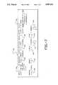
- FIG. 7is a plan view of another control panel for the decoding system of FIGS. 1-4.
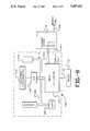
- FIG. 8is a further block diagram of the decoding system of FIGS. 1-4.
- FIG. 1there is shown a decoding system 10, which receives a composite digital NTSC D2 input signal on line 12 or a composite analog NTSC RS-170A input signal on line 14.
- the decoding system 10decodes and sample rate converts to a component digital D1 output on line 16 and a component analog RGB or Y(R-Y)(B-Y) output on line 18.
- a control panel 20is connected by line 22 to the decoding system 10 to provide digital control of the important decoding parameters to provide decoding flexibility.
- FIG. 2shows the basic functions that are provided within the decoding system 10.
- the composite analog NTSC RS-170A input at 14is converted to digital form by an A/D converter 24.
- the composite NTSC D2 bus signal at 12is received at 26.
- Switch 28allows selection of the composite input signal to the decoding system 10.
- the composite input signalis separated into its luminance and chrominance components at 30 and converted from a 14.3 MHz D2 rate to a 13.5 MHz D1 rate at 32.
- Enhancement of the luminance and chrominance components of the input signalis carried out at 34.
- the enhanced signalis formatted as a D1 output by formatter 36 and supplied on line 16 or converted to analog form by a D/A converter 38 and supplied on line 18.
- the digital composite video signalis supplied on line 40 to a difference circuit 42. It is also supplied directly to an adaptive combiner 44 on line 46, through a line comb filter 48 on line 50 to the adaptive combiner 44, and through a frame comb filter 52 on line 54 to the adaptive combiner 44.
- the digital composite video signalis also supplied on line 56 to a frame transition or motion detector 58 and to a line transition or motion detector 60.
- the function of the frame transition or motion detector 58is to determine whether there is frame to frame motion in a scene represented by the video signal. If no frame transition or motion is detected, the adaptive combiner 44 utilizes frame based three dimensional decoding. The three dimensional process produces the very best decoding of video by eliminating the cross-luminance and cross-chrominance artifacts from the output picture. When frame transition or motion is detected, the adaptive combiner 44 drops back to two dimensional line combing for the decoding.
- the function of the line transition or motion detector 60is to determine whether there is line to line transition or motion in a scene represented by the video signal. When such line transition or motion is detected, the adaptive combiner drops back to supply the video signal directly to band pass filter 62 for bandpass decoding.
- the decoding system 10automatically adapts to line combing or bandpass decoding smoothly within the scene.
- the transition or motion determinations and the changes in decoding mode selected on the basis of the determinationsare carried out rapidly enough to allow the adaptation on a line-by-line or even a pixel-by-pixel basis within a line.
- a composite video input signalis supplied to delay element 80.
- the input to delay element 118is divided by four and supplied to summing circuit 77.
- the output of delay element 118is divided by two and supplied to the summing circuit 77.
- the output of the delay element 118is also supplied to summing circuit 95.
- the output of delay element 120is divided by four and supplied to the summing circuit 77.
- the unprocessed output of delay element 118is supplied directly to summing circuit 42 and through bandpass filter 83 in the adaptive combiner 44 as a ID input to cross fade amplifier circuit 85.
- the output of the line comb filter 48is supplied through bandpass filter 87 as a 2D input to the cross fade amplifier circuit 85.
- the output of delay element 80 and the output of delay element 120are supplied as + and - inputs to summing circuit 116.
- the output of the summing circuit 116is supplied through a bandpass filter 89 to rectifier 124.
- the output of rectifier 124is supplied undelayed and delayed by 1H delay element 126 to summing circuit 128.
- the output of the summing circuit 128is supplied through a low pass filter 91 and a threshold detector 93 as a control input for the cross fade amplifier circuit 85.
- the composite video input signal and the output of delay element 82are supplied as negative inputs to summing circuit 95.
- the output of delay element 118, divided by two,is supplied as a positive input to the summing circuit 95.
- the output of the summing circuit 95is supplied as a 3D input to cross fade amplifier 97.
- the other input to the cross fade amplifier 97is the output of the cross fade amplifier 85.
- the composite video input and the output of delay element 82are supplied as positive and negative inputs to summing circuit 78.
- the output of the summing circuit 78is supplied through bandpass filter 99 to rectifier 88.
- the output of rectifier 88is supplied undelayed and delayed by 1F delay element 110 to summing circuit 112.
- the output of the summing circuit 112is supplied to summing circuit 101, which serves to sum together the two legs of the frame motion detector.
- the other input to summing circuit 101is the output of the summing circuit 95 in the frame comb filter 52, supplied through low pass filter 103 and rectifier 105.
- the output of the summing circuit 101is supplied through a low pass filter 107 as an undelayed input to summing circuit 109 and through delay element 111 as a delayed input to the summing circuit 109.
- the output of the summing circuit 109is supplied through threshold, which functions as a comparator, which compares the frame motion against the threshold, as a control input to the cross fade amplifier 97.
- the outputs of the line motion summing circuit 116 and the frame motion summing circuit 78each contain both luminance and chrominance components.
- the bandpass filters 89 and 99eliminate unwanted components in the outputs. This is desirable in order to prevent the motion detectors 58 and 60 from being hyperactive and responding when not needed by increasing the signal to noise ratio.
- the low pass filter 103 and the rectifier 105are provided to remove the chrominance differences from the output of the summing circuit 95 of the frame comb filter 52 and supply that output as an additional path to the frame motion detector.
- This secondary legprovides additional motion detection in regions where the primary leg is insensitive.
- the delay element 111 and the summing circuit 109form a horizontal expansion circuit, which increases the region covered by the motion detector.
- separate bandpass filters 83 and 87are provided in the 1D and 2 D outputs, but not in the 3D output, in place of the single band pass filter 62 in FIG. 3 for all three outputs. Eliminating a bandpass filter in the 3D output path avoids cutting into the chrominance bandwidth for signals that are not properly bandwidth limited according to NTSC specifications. Providing separate bandpass filters for the 2D and 1D outputs eliminates certain signal glitches associated with cross fading.
- the separated chrominance signal from the composite video signalis subtracted from the input composite video signal at 42 to give a separated luminance signal Y on line 64.
- the separated chrominance signalis demodulated by demodulators 66 and 68 to give an I component on line 70 and a Q component on line 72. Further details on the I and Q component separation are available in Parker, "A Method of Obtaining the Advantages of I and Q Detection with Direct or Color Difference Type Demodulators," (citation to be supplied), pp. 12-18, the disclosure of which is hereby incorporated by reference herein.
- FIG. 5Ashows the I sidebands 140 of the chroma signal at +/-3.58 MHz before low pass filtering.
- FIG. 5Bshows one of the I sidebands 140 after low pass filtering.
- a step filter having the characteristics 150 shown in FIG. 5Cshould be used. This turns out to be hard to do with a 32-tap digital filter that is decimating 4:1, i.e., originally only 8 taps. It works fine with 64 taps, but this would be too expensive. A single sideband technique is therefore used instead.
- FIG. 5Hshows output signal 158 of a bandpass filter.
- Such filtersare easily designed with windows. If a window that tapers to 0 is used, such as a Hanning window, then two extra taps are obtained.
- FIG. 6shows a front control panel 170 for the decoding system 10.
- Knobs 172-184respectively control rotary potentiometers for adjusting input signal gain, hue, saturation, luminance high frequency enhancement, chrominance high frequency enhancement, luminance horizontal-vertical ratio enhancement and chrominance I-Q ratio enhancement.
- Gain 172is variable between -3 dB and +3 dB in 0.25 dB steps.
- Hue 174is variable between +/- 15° in 1° steps.
- Saturation 176is variable between -3 dB and +3 dB in 0.25 dB steps.
- Luminance enhancement 178 and 182is variable between 0-6 dB boost in 0.25 dB steps, with the H/V ratio being variable between 0-100%.
- Chrominance enhancement 180 and 184is variable between 0-6 dB boost in 0.25 dB steps, with the I/Q ratio being variable between 0-100%.
- Mode switch 186sequentially cycles among 3-D, 2-D, 1-D and black and white 3-D operation for the adaptive combiner (FIG. 3).
- the usual modeis 3-D, in which the adaptive combiner selects from 3-D, 2-D and 1-D operation dynamically, based on the analysis of the detectors 58 and 60, as described previously.
- Black and white 3-Dis the corresponding mode for a black and white composite video input signal.
- Memory switches 188allow selection among a default set of unity values for the selectable parameters and four preset combinations of the selectable parameters previously stored by the user.
- Save switch 190allows a set of selected parameters to be stored as one of the four preset combinations as chosen with the memory switches 88.
- Display switch 192will overlay current/chosen preset parameters which are always shown on a separate display overlaid on the video image and also selects which of two video pages are displayed. When a preset combination of parameters is selected, adjustment of the controls 172-184 has no effect, until the adjustment of a parameter passes through its value in the preset combination.
- FIG. 7shows an inner control panel 200 for the decoding system 10.
- Switch 202allows selection among D2 parallel, D2 serial, RS-170A analog and test signal inputs.
- I/Q bandwidth switch 204selects between normal and equiband operation.
- Switch 206selects between a reference with the input signal or a separate external reference.
- Switch 208selects 8-bit or 10-bit digital output resolution.
- Switch 210selects among the indicated test modes.
- Control switch 212selects between control from the panels 170 and 200 on the decoding system 10 or the corresponding remote panel 20 (FIG. 1), connected to the decoding system 10 by an RS-422 port.
- Freeze switch 214selects the current frame for display until toggled off.
- Knob 216 and switch 218select Y/C delay, variable between +/-0.5 microseconds in 9 nanosecond steps.
- Knob 220 and switch 222select output setup between 0-15 IRE in 0.5 IRE steps; or pass through. Varying this parameter determines scene black level.
- FIG. 8is a block diagram of a control system 230 for the decoding system 10.
- an 80C31 type microprocessor integrated circuit 232receives inputs from adjustment potentiometers 234 of the control panels 170 and 200 through an A/D converter 236 on bus 238.
- the switches of the control panels 170 and 200supply inputs to the microprocessor 232 on bus 238.
- Corresponding inputsare provided by the remote control panel 20 on RS-422 port 22 when remote operation is selected.
- Bidirectional bus 242supplies outputs from the microprocessor to the decoding unit 10 and receives inputs for the microprocessor 232 from the decoding unit 10.
- Line 244supplies text outputs from the microprocessor 232 for output by the decoding unit on line 246 for separate and overlaid display on a video monitor.
- Bus 238provides outputs from the microprocessor 232 for LED's 250 on the control panels 170 and 200.
- Appendix I to this description and forming a part hereofis a commented assembler source code listing of a control program for the microprocessor 232, which is stored in a PROM 252 connected to the microprocessor 232 by bus 238.
- Appendix II to this description and forming a part hereofis a lookup table, also stored in the PROM 252, used with the control program in the microprocessor 232.
- the system and methodcarries out automatic control of decoding mode within a scene on a line to line and even pixel to pixel basis, determined by characteristics of the video signal being decoded.
- the systemfurther allows user control of signal parameters on a frame by frame basis.
- the video signal composite to component decoding system and methodwill maintain apparent high image resolution while eliminating visual artifacts which would otherwise be introduced by the decoding.
- the decoding system and methodprovides digital control of important video correction and decoding parameters.
- the decoding system and methoddoes not require any special pre-filtering in the encoding process beforehand.
Landscapes
- Engineering & Computer Science (AREA)
- Multimedia (AREA)
- Signal Processing (AREA)
- Processing Of Color Television Signals (AREA)
Abstract
Description
symmetric : h(t)=cos(2πf.sub.w t) · sinc(f.sub.w t)
antisymmetric: h(t)=sin(2αf.sub.w t) · sinc(f.sub.w t),
Claims (52)
Priority Applications (3)
| Application Number | Priority Date | Filing Date | Title |
|---|---|---|---|
| US07/408,027US5097321A (en) | 1989-04-28 | 1989-09-15 | Three dimensional adaptive decoding system and method |
| PCT/US1990/002199WO1990013979A1 (en) | 1989-04-28 | 1990-04-26 | Three dimensional adaptive decoding system and method |
| EP19900907958EP0422210A4 (en) | 1989-04-28 | 1990-04-26 | Three dimensional adaptive decoding system and method |
Applications Claiming Priority (2)
| Application Number | Priority Date | Filing Date | Title |
|---|---|---|---|
| US34506689A | 1989-04-28 | 1989-04-28 | |
| US07/408,027US5097321A (en) | 1989-04-28 | 1989-09-15 | Three dimensional adaptive decoding system and method |
Related Parent Applications (1)
| Application Number | Title | Priority Date | Filing Date |
|---|---|---|---|
| US34506689AContinuation-In-Part | 1989-04-28 | 1989-04-28 |
Publications (1)
| Publication Number | Publication Date |
|---|---|
| US5097321Atrue US5097321A (en) | 1992-03-17 |
Family
ID=26994236
Family Applications (1)
| Application Number | Title | Priority Date | Filing Date |
|---|---|---|---|
| US07/408,027Expired - LifetimeUS5097321A (en) | 1989-04-28 | 1989-09-15 | Three dimensional adaptive decoding system and method |
Country Status (3)
| Country | Link |
|---|---|
| US (1) | US5097321A (en) |
| EP (1) | EP0422210A4 (en) |
| WO (1) | WO1990013979A1 (en) |
Cited By (17)
| Publication number | Priority date | Publication date | Assignee | Title |
|---|---|---|---|---|
| US5194942A (en)* | 1990-06-30 | 1993-03-16 | Samsung Electronics Co., Ltd. | Variable bandwidth control apparatus for separating luminance and chrominance signals and the method thereof |
| US5416532A (en)* | 1993-03-17 | 1995-05-16 | Samsung Electronics Co., Ltd. | Adaptive video peaking circuitry using cross-faders |
| US5473389A (en)* | 1992-11-10 | 1995-12-05 | Sony Corporation | Y/C separator using 3-D, 2-D and 1-D filters |
| US5541669A (en)* | 1990-03-29 | 1996-07-30 | Mitsubishi Denki Kabushiki Denki | Motion adaptive luminance signal and color signal separation filter |
| US5926220A (en)* | 1997-06-18 | 1999-07-20 | C-Cube Microsystems, Inc. | Composite digital video decoder and digital compressor |
| US5953480A (en)* | 1995-07-15 | 1999-09-14 | U.S. Philips Corporation | Comb filter arrangement |
| US20040119890A1 (en)* | 2002-12-20 | 2004-06-24 | Silicon Integrated Systems Corp. | Method for detecting video frame types with adaptive thresholds |
| US6914638B2 (en)* | 2000-12-20 | 2005-07-05 | Intel Corporation | Three-dimensional enhancement processing for television broadcasting signals |
| US7030901B2 (en) | 2001-04-16 | 2006-04-18 | Hynix Semiconductor Inc. | Methods and apparatus for removing NTSC signals from a digital television signal |
| US20060221249A1 (en)* | 2005-03-30 | 2006-10-05 | Samsung Electronics Co., Ltd. | Dual-channel adaptive 2D noise reduction for video signals |
| US7304688B1 (en) | 2003-05-20 | 2007-12-04 | Pixelworks, Inc. | Adaptive Y/C separator |
| US7327405B1 (en)* | 2003-04-04 | 2008-02-05 | Qustream Corporation | Systems and methods for improved video comb filtering with dynamic chroma bandwidth control |
| US7365796B1 (en) | 2003-05-20 | 2008-04-29 | Pixelworks, Inc. | System and method for video signal decoding using digital signal processing |
| US7420625B1 (en) | 2003-05-20 | 2008-09-02 | Pixelworks, Inc. | Fuzzy logic based adaptive Y/C separation system and method |
| US7532254B1 (en) | 2003-05-20 | 2009-05-12 | Pixelworks, Inc. | Comb filter system and method |
| US7605867B1 (en) | 2003-05-20 | 2009-10-20 | Pixelworks, Inc. | Method and apparatus for correction of time base errors |
| US7701512B1 (en) | 2003-05-20 | 2010-04-20 | Pixelworks, Inc. | System and method for improved horizontal and vertical sync pulse detection and processing |
Families Citing this family (4)
| Publication number | Priority date | Publication date | Assignee | Title |
|---|---|---|---|---|
| KR960016852B1 (en)* | 1990-05-23 | 1996-12-21 | 삼성전자 주식회사 | Motion Adaptive Color Signal Synthesis Circuit |
| GB2293511A (en)* | 1994-09-14 | 1996-03-27 | Vistek Electronics | Colour television decoder using a 3D filter |
| KR100202565B1 (en)* | 1996-03-23 | 1999-06-15 | 구자홍 | 3D luminance / color signal separation device of composite video signal |
| GB9607592D0 (en)* | 1996-04-12 | 1996-06-12 | Snell & Wilcox Ltd | Encoding and decoding of composite video signals |
Citations (10)
| Publication number | Priority date | Publication date | Assignee | Title |
|---|---|---|---|---|
| JPS55123280A (en)* | 1979-03-16 | 1980-09-22 | Nippon Hoso Kyokai <Nhk> | Luminance and chromaticity signal separator |
| US4258385A (en)* | 1979-05-15 | 1981-03-24 | Combined Logic Company | Interactive video production system and method |
| GB2078054A (en)* | 1980-06-02 | 1981-12-23 | British Broadcasting Corp | PAL decoding |
| JPS5972889A (en)* | 1982-10-19 | 1984-04-24 | Sony Corp | Transmitting device of digital color video signal |
| JPS5977782A (en)* | 1982-10-25 | 1984-05-04 | Sony Corp | Y/c separating circuit |
| US4641180A (en)* | 1983-04-04 | 1987-02-03 | Robert Bosch Gmbh | Electronic circuit apparatus for separating the luminance and color information of a color television signal |
| JPS62136191A (en)* | 1985-12-09 | 1987-06-19 | Hitachi Ltd | signal processing circuit |
| US4694329A (en)* | 1984-04-09 | 1987-09-15 | Corporate Communications Consultants, Inc. | Color correction system and method with scene-change detection |
| US4754322A (en)* | 1985-09-30 | 1988-06-28 | Hitachi, Ltd. | YC-signal separation circuit responsive to magnitude of vertical correlation |
| US4870661A (en)* | 1986-09-30 | 1989-09-26 | Kabushiki Kaisha Toshiba | Sample rate conversion system having interpolation function |
Family Cites Families (3)
| Publication number | Priority date | Publication date | Assignee | Title |
|---|---|---|---|---|
| GB2116393B (en)* | 1977-04-15 | 1984-02-15 | British Broadcasting Corp | Colour television signal processing |
| US4716462A (en)* | 1986-11-25 | 1987-12-29 | Rca Corporation | Motion adaptive television signal processing system |
| US4703341A (en)* | 1987-01-12 | 1987-10-27 | Rca Corporation | Television having luma/chroma separation apparatus |
- 1989
- 1989-09-15USUS07/408,027patent/US5097321A/ennot_activeExpired - Lifetime
- 1990
- 1990-04-26EPEP19900907958patent/EP0422210A4/ennot_activeWithdrawn
- 1990-04-26WOPCT/US1990/002199patent/WO1990013979A1/ennot_activeApplication Discontinuation
Patent Citations (10)
| Publication number | Priority date | Publication date | Assignee | Title |
|---|---|---|---|---|
| JPS55123280A (en)* | 1979-03-16 | 1980-09-22 | Nippon Hoso Kyokai <Nhk> | Luminance and chromaticity signal separator |
| US4258385A (en)* | 1979-05-15 | 1981-03-24 | Combined Logic Company | Interactive video production system and method |
| GB2078054A (en)* | 1980-06-02 | 1981-12-23 | British Broadcasting Corp | PAL decoding |
| JPS5972889A (en)* | 1982-10-19 | 1984-04-24 | Sony Corp | Transmitting device of digital color video signal |
| JPS5977782A (en)* | 1982-10-25 | 1984-05-04 | Sony Corp | Y/c separating circuit |
| US4641180A (en)* | 1983-04-04 | 1987-02-03 | Robert Bosch Gmbh | Electronic circuit apparatus for separating the luminance and color information of a color television signal |
| US4694329A (en)* | 1984-04-09 | 1987-09-15 | Corporate Communications Consultants, Inc. | Color correction system and method with scene-change detection |
| US4754322A (en)* | 1985-09-30 | 1988-06-28 | Hitachi, Ltd. | YC-signal separation circuit responsive to magnitude of vertical correlation |
| JPS62136191A (en)* | 1985-12-09 | 1987-06-19 | Hitachi Ltd | signal processing circuit |
| US4870661A (en)* | 1986-09-30 | 1989-09-26 | Kabushiki Kaisha Toshiba | Sample rate conversion system having interpolation function |
Non-Patent Citations (7)
| Title |
|---|
| Kaiser, Arthur; "Comb Filter Improvement With Spurious Chroma Deletion"; SMPTE Journal, Jan. 1977; pp. 1-5. |
| Kaiser, Arthur; Comb Filter Improvement With Spurious Chroma Deletion ; SMPTE Journal , Jan. 1977; pp. 1 5.* |
| Lagoni, W. A. et al.; "A Base-Band Comb Filter for Consumer Television Receivers"; IEEE Transactions on Consumer Electronics, vol. CE-26; Feb. 1980; pp. 94-98. |
| Lagoni, W. A. et al.; A Base Band Comb Filter for Consumer Television Receivers ; IEEE Transactions on Consumer Electronics , vol. CE 26; Feb. 1980; pp. 94 98.* |
| Parker, N. W.; A Method of Obtaining the Advantages of I and Q Detection With Direct or Color Different Type Demodulators.* |
| Teichner, Detief; "Three-Dimensional Pre- and Post-Filtering for PAL TV Signals"; IEEE Transactions on Consumer Electronics, vol. 34, No. 1, Feb. 1988; pp. 205-227. |
| Teichner, Detief; Three Dimensional Pre and Post Filtering for PAL TV Signals ; IEEE Transactions on Consumer Electronics , vol. 34, No. 1, Feb. 1988; pp. 205 227.* |
Cited By (22)
| Publication number | Priority date | Publication date | Assignee | Title |
|---|---|---|---|---|
| US5541669A (en)* | 1990-03-29 | 1996-07-30 | Mitsubishi Denki Kabushiki Denki | Motion adaptive luminance signal and color signal separation filter |
| US5194942A (en)* | 1990-06-30 | 1993-03-16 | Samsung Electronics Co., Ltd. | Variable bandwidth control apparatus for separating luminance and chrominance signals and the method thereof |
| US5473389A (en)* | 1992-11-10 | 1995-12-05 | Sony Corporation | Y/C separator using 3-D, 2-D and 1-D filters |
| US5416532A (en)* | 1993-03-17 | 1995-05-16 | Samsung Electronics Co., Ltd. | Adaptive video peaking circuitry using cross-faders |
| US5953480A (en)* | 1995-07-15 | 1999-09-14 | U.S. Philips Corporation | Comb filter arrangement |
| US5926220A (en)* | 1997-06-18 | 1999-07-20 | C-Cube Microsystems, Inc. | Composite digital video decoder and digital compressor |
| US6914638B2 (en)* | 2000-12-20 | 2005-07-05 | Intel Corporation | Three-dimensional enhancement processing for television broadcasting signals |
| US7030901B2 (en) | 2001-04-16 | 2006-04-18 | Hynix Semiconductor Inc. | Methods and apparatus for removing NTSC signals from a digital television signal |
| US20040119890A1 (en)* | 2002-12-20 | 2004-06-24 | Silicon Integrated Systems Corp. | Method for detecting video frame types with adaptive thresholds |
| US6992727B2 (en)* | 2002-12-20 | 2006-01-31 | Silicon Integrated Systems Corp. | Method for detecting video frame types with adaptive thresholds |
| US7327405B1 (en)* | 2003-04-04 | 2008-02-05 | Qustream Corporation | Systems and methods for improved video comb filtering with dynamic chroma bandwidth control |
| US7420625B1 (en) | 2003-05-20 | 2008-09-02 | Pixelworks, Inc. | Fuzzy logic based adaptive Y/C separation system and method |
| US7304688B1 (en) | 2003-05-20 | 2007-12-04 | Pixelworks, Inc. | Adaptive Y/C separator |
| US7365796B1 (en) | 2003-05-20 | 2008-04-29 | Pixelworks, Inc. | System and method for video signal decoding using digital signal processing |
| US7391472B1 (en) | 2003-05-20 | 2008-06-24 | Pixelworks, Inc. | System and method for adaptive color burst phase correction |
| US7532254B1 (en) | 2003-05-20 | 2009-05-12 | Pixelworks, Inc. | Comb filter system and method |
| US7605867B1 (en) | 2003-05-20 | 2009-10-20 | Pixelworks, Inc. | Method and apparatus for correction of time base errors |
| US7646436B1 (en) | 2003-05-20 | 2010-01-12 | Pixelworks, Inc. | Fuzzy logic based adaptive Y/C separation system and method |
| US7701512B1 (en) | 2003-05-20 | 2010-04-20 | Pixelworks, Inc. | System and method for improved horizontal and vertical sync pulse detection and processing |
| US20060221249A1 (en)* | 2005-03-30 | 2006-10-05 | Samsung Electronics Co., Ltd. | Dual-channel adaptive 2D noise reduction for video signals |
| US7522220B2 (en)* | 2005-03-30 | 2009-04-21 | Samsung Electronics Co., Ltd. | Dual-channel adaptive 2D noise reduction for video signals |
| US7742110B1 (en) | 2005-07-22 | 2010-06-22 | Pixelworks, Inc. | Comb filter system and method |
Also Published As
| Publication number | Publication date |
|---|---|
| EP0422210A1 (en) | 1991-04-17 |
| WO1990013979A1 (en) | 1990-11-15 |
| EP0422210A4 (en) | 1992-07-08 |
Similar Documents
| Publication | Publication Date | Title |
|---|---|---|
| US5097321A (en) | Three dimensional adaptive decoding system and method | |
| US5347314A (en) | Video scan converter | |
| US4754322A (en) | YC-signal separation circuit responsive to magnitude of vertical correlation | |
| US4924305A (en) | Motion detecting circuit for video signal processing using correlation techniques | |
| US5526060A (en) | Luma/chroma decoder with demodulated control signal | |
| US5063438A (en) | Three dimensional encoding system for color television | |
| US5424784A (en) | Method and apparatus for cross fading between combed and simple filtered outputs | |
| US5583579A (en) | Two-dimensional adaptation type luminance/chrominance signal separation apparatatus | |
| KR20080055718A (en) | TV user interface and processing for personal video players | |
| US5225899A (en) | Correlation adaptive luminance and chrominance signal separating circuit | |
| US5107340A (en) | Digital video signal noise-reduction apparatus with high pass and low pass filter | |
| US5225907A (en) | Television signal scan conversion system with reduced noise sensitivity | |
| JPH0846999A (en) | Digital device and method for decoding video signal | |
| US5235417A (en) | Television signal scan conversion system with motion adaptive processing | |
| US5475445A (en) | Motion adaptive luminance signal and color signal separation filter | |
| US5170248A (en) | Motion-adaptive vertical contour compensator in television set | |
| JP2617622B2 (en) | Motion adaptive color signal synthesis method and circuit | |
| US7224406B2 (en) | Digital signal processing system and method applied for chroma transition | |
| US5929938A (en) | Motion adaptive luminance and chrominance signal separating circuit | |
| US6333764B1 (en) | Video signal luminance and chrominance separation | |
| US20060077301A1 (en) | Secam color difference signal processing method | |
| KR940001442B1 (en) | Luminance and chroma signal separation system | |
| JP2848946B2 (en) | Television signal processing circuit | |
| JP2878776B2 (en) | Luminance signal color signal separation filter | |
| JP3003178B2 (en) | Luminance signal color signal separation filter |
Legal Events
| Date | Code | Title | Description |
|---|---|---|---|
| AS | Assignment | Owner name:ACCOM, CALIFORNIA Free format text:ASSIGNMENT OF ASSIGNORS INTEREST.;ASSIGNORS:STERN, JOHN;GALLO, LUIGI C.;GEORGE, DOUGLASS JAMES;REEL/FRAME:005143/0518 Effective date:19890915 | |
| STCF | Information on status: patent grant | Free format text:PATENTED CASE | |
| FPAY | Fee payment | Year of fee payment:4 | |
| AS | Assignment | Owner name:COMERICA BANK-CALIFORNIA, CALIFORNIA Free format text:SECURITY AGREEMENT;ASSIGNOR:ACCOM, INC.;REEL/FRAME:008146/0233 Effective date:19960707 | |
| AS | Assignment | Owner name:LASALLE BUSINESS CREDIT, INC., OREGON Free format text:SECURITY INTEREST;ASSIGNOR:ACCOM INC., A DELAWARE CORPORATION;REEL/FRAME:009996/0712 Effective date:19981210 | |
| FPAY | Fee payment | Year of fee payment:8 | |
| AS | Assignment | Owner name:ACCOM, INC., CALIFORNIA Free format text:SECURITY AGREEMENT;ASSIGNOR:LA SALLE BUSINESS CREDIT, INC.;REEL/FRAME:011425/0107 Effective date:20000121 | |
| AS | Assignment | Owner name:ACCOM, INC., CALIFORNIA Free format text:RELEASE;ASSIGNOR:LASALLE BUSINESS CREDIT, INC.;REEL/FRAME:011442/0132 Effective date:20001130 | |
| AS | Assignment | Owner name:ACCOM, INC., CALIFORNIA Free format text:SECURITY AGREEMENT;ASSIGNOR:LA SALLE BUSINESS CREDIT, INC.;REEL/FRAME:011967/0389 Effective date:20000121 | |
| FPAY | Fee payment | Year of fee payment:12 | |
| AS | Assignment | Owner name:TOMAS RECORDINGS LLC, NEVADA Free format text:ASSIGNMENT OF ASSIGNORS INTEREST;ASSIGNOR:ACCOM, INC.;REEL/FRAME:017892/0430 Effective date:20050922 | |
| FEPP | Fee payment procedure | Free format text:PAT HOLDER NO LONGER CLAIMS SMALL ENTITY STATUS, ENTITY STATUS SET TO UNDISCOUNTED (ORIGINAL EVENT CODE: STOL); ENTITY STATUS OF PATENT OWNER: LARGE ENTITY |