US5097241A - Cooling apparatus for windings - Google Patents
Cooling apparatus for windingsDownload PDFInfo
- Publication number
- US5097241A US5097241AUS07/459,000US45900089AUS5097241AUS 5097241 AUS5097241 AUS 5097241AUS 45900089 AUS45900089 AUS 45900089AUS 5097241 AUS5097241 AUS 5097241A
- Authority
- US
- United States
- Prior art keywords
- windings
- conduit
- leg
- coolant
- turns
- Prior art date
- Legal status (The legal status is an assumption and is not a legal conclusion. Google has not performed a legal analysis and makes no representation as to the accuracy of the status listed.)
- Expired - Fee Related
Links
- 238000004804windingMethods0.000titleclaimsabstractdescription72
- 238000001816coolingMethods0.000titleclaimsabstractdescription36
- 239000002826coolantSubstances0.000claimsabstractdescription29
- RYGMFSIKBFXOCR-UHFFFAOYSA-NCopperChemical compound[Cu]RYGMFSIKBFXOCR-UHFFFAOYSA-N0.000claimsdescription6
- 229910052802copperInorganic materials0.000claimsdescription6
- 239000010949copperSubstances0.000claimsdescription6
- 229910052751metalInorganic materials0.000claimsdescription5
- 239000002184metalSubstances0.000claimsdescription5
- 229910052782aluminiumInorganic materials0.000claimsdescription3
- XAGFODPZIPBFFR-UHFFFAOYSA-NaluminiumChemical compound[Al]XAGFODPZIPBFFR-UHFFFAOYSA-N0.000claimsdescription3
- RTAQQCXQSZGOHL-UHFFFAOYSA-NTitaniumChemical compound[Ti]RTAQQCXQSZGOHL-UHFFFAOYSA-N0.000claimsdescription2
- 229910045601alloyInorganic materials0.000claimsdescription2
- 239000000956alloySubstances0.000claimsdescription2
- 239000007767bonding agentSubstances0.000claimsdescription2
- 239000010935stainless steelSubstances0.000claimsdescription2
- 229910001220stainless steelInorganic materials0.000claimsdescription2
- 229910052719titaniumInorganic materials0.000claimsdescription2
- 239000010936titaniumSubstances0.000claimsdescription2
- 239000007788liquidSubstances0.000description3
- 239000000463materialSubstances0.000description3
- 230000002411adverseEffects0.000description2
- 230000006378damageEffects0.000description2
- 238000005553drillingMethods0.000description2
- 238000009413insulationMethods0.000description2
- 238000003475laminationMethods0.000description2
- RETIMRUQNCDCQB-UHFFFAOYSA-Nmepivacaine hydrochlorideChemical compoundCl.CN1CCCCC1C(=O)NC1=C(C)C=CC=C1CRETIMRUQNCDCQB-UHFFFAOYSA-N0.000description2
- 238000000059patterningMethods0.000description2
- 239000004593EpoxySubstances0.000description1
- 239000000919ceramicSubstances0.000description1
- 239000004020conductorSubstances0.000description1
- 238000010276constructionMethods0.000description1
- 230000002500effect on skinEffects0.000description1
- 239000002657fibrous materialSubstances0.000description1
- 239000012530fluidSubstances0.000description1
- 238000010438heat treatmentMethods0.000description1
- 150000002739metalsChemical class0.000description1
- 238000012986modificationMethods0.000description1
- 230000004048modificationEffects0.000description1
- 238000007493shaping processMethods0.000description1
- 125000006850spacer groupChemical group0.000description1
Images

Classifications
- H—ELECTRICITY
- H01—ELECTRIC ELEMENTS
- H01F—MAGNETS; INDUCTANCES; TRANSFORMERS; SELECTION OF MATERIALS FOR THEIR MAGNETIC PROPERTIES
- H01F27/00—Details of transformers or inductances, in general
- H01F27/08—Cooling; Ventilating
- H01F27/10—Liquid cooling
- H—ELECTRICITY
- H01—ELECTRIC ELEMENTS
- H01F—MAGNETS; INDUCTANCES; TRANSFORMERS; SELECTION OF MATERIALS FOR THEIR MAGNETIC PROPERTIES
- H01F27/00—Details of transformers or inductances, in general
- H01F27/28—Coils; Windings; Conductive connections
- H01F27/2876—Cooling
- Y—GENERAL TAGGING OF NEW TECHNOLOGICAL DEVELOPMENTS; GENERAL TAGGING OF CROSS-SECTIONAL TECHNOLOGIES SPANNING OVER SEVERAL SECTIONS OF THE IPC; TECHNICAL SUBJECTS COVERED BY FORMER USPC CROSS-REFERENCE ART COLLECTIONS [XRACs] AND DIGESTS
- Y10—TECHNICAL SUBJECTS COVERED BY FORMER USPC
- Y10S—TECHNICAL SUBJECTS COVERED BY FORMER USPC CROSS-REFERENCE ART COLLECTIONS [XRACs] AND DIGESTS
- Y10S174/00—Electricity: conductors and insulators
- Y10S174/13—High voltage cable, e.g. above 10kv, corona prevention
- Y10S174/14—High voltage cable, e.g. above 10kv, corona prevention having a particular cable application, e.g. winding
- Y10S174/24—High voltage cable, e.g. above 10kv, corona prevention having a particular cable application, e.g. winding in an inductive device, e.g. reactor, electromagnet
- Y10S174/25—Transformer
- Y—GENERAL TAGGING OF NEW TECHNOLOGICAL DEVELOPMENTS; GENERAL TAGGING OF CROSS-SECTIONAL TECHNOLOGIES SPANNING OVER SEVERAL SECTIONS OF THE IPC; TECHNICAL SUBJECTS COVERED BY FORMER USPC CROSS-REFERENCE ART COLLECTIONS [XRACs] AND DIGESTS
- Y10—TECHNICAL SUBJECTS COVERED BY FORMER USPC
- Y10S—TECHNICAL SUBJECTS COVERED BY FORMER USPC CROSS-REFERENCE ART COLLECTIONS [XRACs] AND DIGESTS
- Y10S174/00—Electricity: conductors and insulators
- Y10S174/13—High voltage cable, e.g. above 10kv, corona prevention
- Y10S174/32—High voltage cable, e.g. above 10kv, corona prevention having means for cooling
Definitions
- the present inventionrelates generally to the cooling of windings, and more particularly to an apparatus for cooling the windings of a transformer.
- a transformeris often used to step up or step down voltage and usually consists of one or more windings wound on a magnetic core.
- electrical energyis transformed into heat energy due in large part to eddy currents and hysteresis losses. Excessive heating of a transformer can cause adverse results, such as reduced efficiency and damage to the transformer.
- most of the heatis produced in the core of the transformer.
- losses in the coredecrease due to the smaller magnitudes of eddy currents.
- heatis produced in the windings due to I 2 R losses and skin effect.
- the heat produced in the windingsincreases with frequency and may cause fatigue and destruction of the windings or may adversely affect other components in the proximity of the transformer. Also the windings must have a large diameter and must be overrated to withstand the heat produced.
- the prior arthas disclosed attempts to cool transformers or parts thereof. However, the prior art devices are not entirely satisfactory for cooling transformer windings during high frequency use.
- German Patent No. 2,218,659discloses a cooling system which includes multiple axial cooling channels disposed concentrically around a transformer core. These channels run parallel to one another and are disposed between groups of concentric windings. The parallel channels are formed by wrapping the windings on coaxial formers of increasing diameter that are placed around the core and supported radially by spacers. The windings are disposed within the cooling channels themselves. Fans blow cooling air through these parallel channels to cool the windings. Because the windings are within the cooling channels, only coolants which do not react with the insulation of the windings can be employed. This system also increases the size of the transformer as there must be space between each concentric group of windings for the passage of air. In addition, since the coaxial formers completely encircle the core, they may undesirably form secondary windings.
- Swiss Patent No. 249,488also appears to disclose several non-enclosed axial cooling channels disposed concentrically around a transformer core which is disposed in an oil bath. These channels run parallel to one another and are formed between groups of high voltage windings. These non-enclosed channels expose the high voltage windings to the coolant and thus limit the type of coolant to ones which do not react with the winding insulation. These channels also are only able to cool the high voltage windings surrounding the channels and not low voltage windings wrapped about the high voltage windings.
- WadhamsU.S. Pat. No. 2,547,065, discloses a transformer cooling system consisting of hollow cooling plates through which coolant passes. These plates are located between the laminations of a transformer core. This system, however, would be inefficient when used to cool sets of transformer windings having a great number of turns since only the innermost windings closest to the cooling plates could be cooled.
- SabolU.S. Pat. No. 2,547,045, also discloses a first cooling system consisting of cooling plates between core laminations of a transformer. The edges of these plates contain tubing for the passage of coolant.
- a second cooling system disclosed by Sabolincludes tubing attached externally to legs of the core. Both these systems, like that disclosed in Wadhams, would be inefficient when used to cool the windings of a transformer having a great many turns.
- a cooling apparatussimply and efficiently cools windings, such as those wrapped around a transformer core.
- a cooling apparatus for windings having two turns disposed about a coil formincludes a thermally conductive, coolant-isolating conduit having a channel therethrough for coolant passage, the conduit being disposed between the turns of the winding in heat transfer relation therewith.
- the preferred embodimentcomprises a cooling apparatus for the windings of a transformer having a core with a plurality of legs, each leg having first and second opposed sides and a set of windings including a number of turns disposed about each leg.
- a first heat exchangeris disposed between the turns of the windings facing the first side of the core leg and a second heat exchanger is disposed between the turns of the winding facing the second side of the core leg.
- Each heat exchangerpreferably comprises a U-shaped, coolant-isolating conduit having two legs and a channel therethrough for the passage of coolant and a closed U-shaped thermally conductive plate in heat transfer contact with the U-shaped conduit.
- a second embodiment of the invention for use with a transformer of the above-described typecomprises a plurality of U-shaped, coolant-isolating conduits having a pair of legs and a channel therethrough for passage of coolant wherein a first conduit leg is disposed between the turns of one set of windings facing the first side of the core leg and a second conduit leg is disposed between the turns of the same set of windings facing the second side of the core leg.
- the present inventionallows the windings of a transformer having a large number of turns to be efficiently cooled during high frequency use employing almost any coolant.
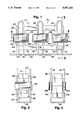
- FIG. 1is a front elevational view of a preferred embodiment of the cooling apparatus of the present invention
- FIG. 2is a side elevational view of the embodiment of FIG. 1;
- FIG. 3is a cross-sectional view taken generally along the lines 3--3 of FIG. 1;
- FIG. 4is a cross-sectional view taken generally along the lines 4--4 of FIG. 1;
- FIG. 5is a front elevational view of the heat exchanger of the present invention.
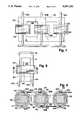
- FIG. 6is a perspective view, partly in section, of an alternative heat exchanger embodiment
- FIG. 7is a front elevational view of a further embodiment of a cooling system according to the present invention.
- FIG. 8is a side elevational view of the embodiment of FIG. 7;
- FIG. 9is a cross-sectional view taken generally along the lines 9--9 of FIG. 8.
- FIGS. 1-5show the preferred embodiment of the present invention.
- a three-phase transformer core 10is formed from two identical, E-shaped laminated core sections 11 and 12, each section having three legs 11A-11C and 12A-12C, respectively.
- the three legs 11A-11C of section 11are butted and held in place by suitable means (not shown) against the three legs 12A-12C of section 12.
- the legs of both sections 11 and 12form three core legs 13A-13C.
- Wrapped around each core leg 13A-13Cis a set of windings 14A-14C, respectively.
- Each set of windings 14A-14Chas at least two turns 17. These turns are lacquered or otherwise insulated to prevent shorting. As best seen in FIG.
- each core leg 13A-13Chas a first side 18A-18C and a second opposite side 20A-20C, respectively.
- heat exchangers 26 of the present inventionare located between the turns 17 of the sets of windings 14A-14C.
- each core leghas one heat exchanger facing the first side 18 and one heat exchanger facing the second side 20, it being understood that the number and location of the heat exchangers 26 may vary, if necessary or desirable.
- each heat exchanger 26comprises a thermally conductive, coolant-isolating, U-shaped conduit 27 and preferably, although not necessarily, a closed U-shaped thermally conductive plate 28.
- the conduit 27has a channel therethrough for the passage of coolant.
- the conduit 27is typically fabricated of non-magnetic round or square metal tubing, such as copper tubing.
- the conduit 27may alternatively be magnetically permeable.
- Each conduit 27has a first leg 30 and a second leg 32 and an interior U-shaped edge 33. The conduit 27 isolates the coolant from the windings 14 and therefore allows most liquid or gaseous coolants to be employed.
- the thermally conductive plate 28may be constructed of a thermally conductive material, preferably, but not limited to non-magnetic metals such as copper, aluminum, titanium, stainless steel or alloys thereof. Ceramic or fibrous materials, though not preferred, may also be used. Aluminum is preferred as it is light in weight.
- the thermally conductive plate 28has a first side 34, a second opposed side 36, and a U-shaped side edge 38. Both the first 34 and second 36 sides of the plate 28 may be flat or curved. If curved, the first side 34 may be convex and the second side 36 concave. This curving of the first and second sides of the plate 28 allows the plate to better conform to the curved shape of the winding turns. This improves the heat transfer contact of the plate with the windings.
- the U-shaped side edge 38 of the platemay also be shaped for better heat transfer with the conduit 27 through which coolant passes.
- the plate 28should preferably, although not necessarily, have a height at least as great as the axial extent of the windings.
- the conduitis fabricated of round tubing and the U-shaped edge 38 in contact with the conduit is concave to allow greater contact, and hence better heat transfer, between the plate 28 and conduit 27.
- the U-shaped side edge 38 of the plate 28is preferably bonded to the interior U-shaped edge 33 of the conduit by a thermally conductive bonding agent, such as epoxy, or is casted or clamped thereto.
- two heat exchangers 26are placed between the turns 17 of the windings about each core leg 13A-13C. This is most easily accomplished by wrapping several turns 17A of the windings on a bobbin, or other turn former, placing the two heat exchangers 26 on opposite outer sides of the turns 17A so that the second sides 36 of the thermally conductive plates 28 contact the turns 17A and then wrapping remaining turns 17B around the bobbin and over the first sides 34 of the thermally conductive plates of the two heat exchangers 26. The bobbin is then removed and the legs 11A-11C and 12A-12C of the E-shaped core sections 11 and 12 are placed within the windings and butted against one another to form the core legs 13A-13C. After this placement, opposed sides 18A-18C and 20A-20C of each core leg 13A-13C face the second side 36 of the thermally conductive plate 28 of one of the heat exchangers 26.
- the heat exchangers 26are thus held in place between the turns 17A and the turns 17B.
- This placement of the heat exchangers 26 within the turns of the windingsallows excellent heat transfer between the windings and the heat exchanger to efficiently cool the windings.
- This heat transferis enhanced by the shaping of the thermally conductive plate 28 which conforms both to the shape of the windings 17 and the shape of the conduit 27.
- the conduits 27 of the heat exchangers 26can be connected in any manner to pass coolant therethrough.
- all the conduits 27are connected in series by connective tubing 29 fabricated of material identical to or similar to that of the U-shaped conduit 27.
- coolantenters the first leg 30 of the heat exchanger conduit 27 facing the first side 18A of core leg 13A and exits the second leg 32 of this conduit.
- Coolantthen passes through connective tubing 29 into the second leg 32 of the heat exchanger conduit 27 facing the second side 20A of core leg 13A and exits the first conduit leg 30.
- Coolantnext passes through connective tubing 29 and enters the second leg 32 of the heat exchanger conduit 27 facing the second side 20B of the core leg 13B and exits the first leg 30 thereof.
- coolantflows in a similar fashion through the heat exchangers 26 facing the sides 18B, 18C and 20C of the legs 13B and 13C and the connective tubing 29 connected therebetween. Since not all the heat exchangers are connected in a closed loop, the metallic tubing of the U-shaped heat exchanger conduits 27 and the connective tubing 29 between the heat exchangers do not form a shorted turn.
- each heat exchangermay instead be of one-piece construction.
- a heat exchanger 40includes a thermally conductive plate 42 through which channels are drilled or otherwised formed to construct a U-shaped conduit 44.
- the plate 42has a first edge 46, a second edge 48 opposed thereto, a third edge 50 and a fourth edge 52 opposed to the third edge.
- the U-shaped conduitis most easily formed by drilling three channels. Two channels are drilled between the first edge 46 and second edge 48 to form a first conduit leg 54 and a second conduit leg 56, respectively.
- a third channel 58is drilled between the third edge 50 and the fourth edge 52. This third channel 58 connects the first leg 54 to the second leg 56.
- the channel openings on the first, third and fourth edges 46, 50, 52 of the plate 42 caused by this drillingare closed by plugs 59 which are preferably constructed of material similar to that of plate 42.
- the plugs 59are secured in the opening in any conventional manner.
- the plate 42may be curved like the plate 28 to improve the heat transfer contact with the windings.
- the plate 42may also be constructed of the same materials as the plate 28.
- the heat exchangers 40may be placed between turns of the windings and be connected by connective tubing in any manner, such as that described previously in connection with the preferred embodiment.
- FIGS. 7, 8 and 9Another embodiment of the present invention is shown in FIGS. 7, 8 and 9 wherein like reference numbers identify the same elements as shown in FIGS. 1-5.
- a three-phase transformer core 10has sets of windings 14A-14C wrapped around core legs 13A-13C, respectively. Each set of windings 14A-14C has at least two turns 17.
- Each core leg 13A-13Chas a first side 18A-18C and an opposed second side 20A-20C, respectively.
- U-shaped thermally conductive, coolant-isolating conduits 60A-60C each having a channel for gaseous or liquid coolant passage therethroughare held in place between the turns 17 of the windings on each core leg.
- Each U-shaped thermally conductive conduithas a first leg 62, a second leg 64 and a connecting portion 66 connecting the first leg 62 to the second leg 64.
- the conduitpreferably, but not necessarily, is constructed of any non-magnetic metallic tubing such as copper tubing.
- each conduit legis held in place between the turns 17A which are wrapped about the core leg and the turns 17B which are wrapped outside each conduit leg 62 and 64 and over turns 17A.
- Each first conduit leg 62is thus located between the turns 17A and 17B facing the first side 18A-18C of a transformer leg 13A-13C and each second conduit leg 44 is located between the turns 17A-17B of the windings facing the second side 20A-20C of the transformer leg 13A-13C, respectively. This positioning between the turns of the windings allows the conduit legs to be in excellent heat transfer contact with a great number of turns of the winding and thus provide efficient cooling of the windings.
- the tubing comprising the first conduit leg 62 and the second conduit leg 64may instead be bent in a zig zag or Z-shaped pattern. This patterning allows the turns of the windings to come in contact with more surface area of the conduit legs. The patterning thus provides more cooling ability than straight conduit legs.
- the connecting portion 66 of the conduitcrosses over the core to connect the first conduit leg 62 to the second conduit leg 64 to allow coolant to pass from the first conduit leg 62 to the second conduit leg 64.
- the conduits 60A-60Cmay each be connected to a coolant reservoir or may be serially connected by connective tubing 69 to allow coolant to pass from one to another in any manner desired.
- the second leg of conduit 60Ais connected to the second leg of conduit 60B and the first leg of conduit 60B is connected to the first leg of conduit 60C thereby allowing coolant to pass from the conduits 60A to 60B to 60C. Since the coolant is enclosed within the conduits and isolated from contact with the windings most any liquid or gaseous coolant can be employed.
Landscapes
- Engineering & Computer Science (AREA)
- Power Engineering (AREA)
- Coils Of Transformers For General Uses (AREA)
Abstract
Description
Claims (8)
Priority Applications (1)
| Application Number | Priority Date | Filing Date | Title |
|---|---|---|---|
| US07/459,000US5097241A (en) | 1989-12-29 | 1989-12-29 | Cooling apparatus for windings |
Applications Claiming Priority (1)
| Application Number | Priority Date | Filing Date | Title |
|---|---|---|---|
| US07/459,000US5097241A (en) | 1989-12-29 | 1989-12-29 | Cooling apparatus for windings |
Publications (1)
| Publication Number | Publication Date |
|---|---|
| US5097241Atrue US5097241A (en) | 1992-03-17 |
Family
ID=23822977
Family Applications (1)
| Application Number | Title | Priority Date | Filing Date |
|---|---|---|---|
| US07/459,000Expired - Fee RelatedUS5097241A (en) | 1989-12-29 | 1989-12-29 | Cooling apparatus for windings |
Country Status (1)
| Country | Link |
|---|---|
| US (1) | US5097241A (en) |
Cited By (56)
| Publication number | Priority date | Publication date | Assignee | Title |
|---|---|---|---|---|
| US5541566A (en)* | 1994-02-28 | 1996-07-30 | Olin Corporation | Diamond-like carbon coating for magnetic cores |
| US5588201A (en)* | 1991-03-21 | 1996-12-31 | Siemens Aktiengesellschaft | Process for producing a cast resin coil |
| US6087583A (en)* | 1997-11-12 | 2000-07-11 | Alcatel | Multiwire parallel conductor |
| US6261437B1 (en) | 1996-11-04 | 2001-07-17 | Asea Brown Boveri Ab | Anode, process for anodizing, anodized wire and electric device comprising such anodized wire |
| US6278353B1 (en) | 1999-11-16 | 2001-08-21 | Hamilton Sundstrand Corporation | Planar magnetics with integrated cooling |
| US6279850B1 (en) | 1996-11-04 | 2001-08-28 | Abb Ab | Cable forerunner |
| US6357688B1 (en) | 1997-02-03 | 2002-03-19 | Abb Ab | Coiling device |
| US6369470B1 (en) | 1996-11-04 | 2002-04-09 | Abb Ab | Axial cooling of a rotor |
| US6376775B1 (en) | 1996-05-29 | 2002-04-23 | Abb Ab | Conductor for high-voltage windings and a rotating electric machine comprising a winding including the conductor |
| US6396187B1 (en) | 1996-11-04 | 2002-05-28 | Asea Brown Boveri Ab | Laminated magnetic core for electric machines |
| US6417456B1 (en) | 1996-05-29 | 2002-07-09 | Abb Ab | Insulated conductor for high-voltage windings and a method of manufacturing the same |
| US6429563B1 (en) | 1997-02-03 | 2002-08-06 | Abb Ab | Mounting device for rotating electric machines |
| US6439497B1 (en) | 1997-02-03 | 2002-08-27 | Abb Ab | Method and device for mounting a winding |
| US6465979B1 (en) | 1997-02-03 | 2002-10-15 | Abb Ab | Series compensation of electric alternating current machines |
| US6525265B1 (en) | 1997-11-28 | 2003-02-25 | Asea Brown Boveri Ab | High voltage power cable termination |
| US6525504B1 (en) | 1997-11-28 | 2003-02-25 | Abb Ab | Method and device for controlling the magnetic flux in a rotating high voltage electric alternating current machine |
| US6577487B2 (en) | 1996-05-29 | 2003-06-10 | Asea Brown Boveri Ab | Reduction of harmonics in AC machines |
| US20030164245A1 (en)* | 2000-04-28 | 2003-09-04 | Claes Areskoug | Stationary induction machine and a cable therefor |
| US6628191B1 (en)* | 1999-05-03 | 2003-09-30 | Aloys Wobben | Inductance arrangement |
| US6646363B2 (en) | 1997-02-03 | 2003-11-11 | Abb Ab | Rotating electric machine with coil supports |
| US6801421B1 (en) | 1998-09-29 | 2004-10-05 | Abb Ab | Switchable flux control for high power static electromagnetic devices |
| US6822363B2 (en) | 1996-05-29 | 2004-11-23 | Abb Ab | Electromagnetic device |
| US6825585B1 (en) | 1997-02-03 | 2004-11-30 | Abb Ab | End plate |
| US6828701B1 (en) | 1997-02-03 | 2004-12-07 | Asea Brown Boveri Ab | Synchronous machine with power and voltage control |
| US6831388B1 (en) | 1996-05-29 | 2004-12-14 | Abb Ab | Synchronous compensator plant |
| US6867674B1 (en) | 1997-11-28 | 2005-03-15 | Asea Brown Boveri Ab | Transformer |
| US6873080B1 (en) | 1997-09-30 | 2005-03-29 | Abb Ab | Synchronous compensator plant |
| US6885273B2 (en) | 2000-03-30 | 2005-04-26 | Abb Ab | Induction devices with distributed air gaps |
| US6891303B2 (en) | 1996-05-29 | 2005-05-10 | Abb Ab | High voltage AC machine winding with grounded neutral circuit |
| US6970063B1 (en) | 1997-02-03 | 2005-11-29 | Abb Ab | Power transformer/inductor |
| US6972505B1 (en) | 1996-05-29 | 2005-12-06 | Abb | Rotating electrical machine having high-voltage stator winding and elongated support devices supporting the winding and method for manufacturing the same |
| US20050280489A1 (en)* | 2004-06-11 | 2005-12-22 | Abb Oy | Cooled multiphase choke assembly |
| US6995646B1 (en) | 1997-02-03 | 2006-02-07 | Abb Ab | Transformer with voltage regulating means |
| US7019429B1 (en) | 1997-11-27 | 2006-03-28 | Asea Brown Boveri Ab | Method of applying a tube member in a stator slot in a rotating electrical machine |
| US7046492B2 (en) | 1997-02-03 | 2006-05-16 | Abb Ab | Power transformer/inductor |
| US7061133B1 (en) | 1997-11-28 | 2006-06-13 | Abb Ab | Wind power plant |
| US20060219921A1 (en)* | 2003-03-12 | 2006-10-05 | Matthias Baca | Laminated core testing device |
| US7141908B2 (en) | 2000-03-01 | 2006-11-28 | Abb Ab | Rotating electrical machine |
| WO2009143643A1 (en)* | 2008-05-27 | 2009-12-03 | Ids Holding Ag | Water-cooled reactor |
| US20100277869A1 (en)* | 2009-09-24 | 2010-11-04 | General Electric Company | Systems, Methods, and Apparatus for Cooling a Power Conversion System |
| WO2011039417A1 (en)* | 2009-09-30 | 2011-04-07 | Trafotek Oy | Method for cooling a coil, coil cooling system and liquid cooled coil |
| US20110140820A1 (en)* | 2009-12-10 | 2011-06-16 | Guentert Iii Joseph J | Hyper-cooled liquid-filled transformer |
| KR101070763B1 (en) | 2010-06-17 | 2011-10-07 | 이성호 | Power unit with cooling system to prevent overheating |
| DE102011007334A1 (en)* | 2011-04-13 | 2012-10-18 | Karl E. Brinkmann GmbH | Liquid-cooled inductive component |
| US20140028427A1 (en)* | 2011-02-02 | 2014-01-30 | Siemens Ltda. | Dry distribution transformer |
| CN104506048A (en)* | 2015-01-15 | 2015-04-08 | 合肥永信等离子技术有限公司 | Plasma all-dimensional vacuum coated power supply and coating method thereof |
| CN104599820A (en)* | 2015-01-06 | 2015-05-06 | 江苏东方四通科技股份有限公司 | Water-cooled transformer for high-power medium-high frequency power supply |
| US20170244306A1 (en)* | 2016-02-24 | 2017-08-24 | Ge Aviation Systems Llc | Method and assembly of a power generation system |
| US20180053593A1 (en)* | 2016-08-22 | 2018-02-22 | Chroma Ate Inc. | Transformer embedded with thermally conductive member |
| US10366817B2 (en)* | 2017-05-02 | 2019-07-30 | General Electric Company | Apparatus and method for passive cooling of electronic devices |
| WO2020101905A1 (en)* | 2018-11-12 | 2020-05-22 | Carrier Corporation | Cooled transformer for an energy storage device |
| US20200395160A1 (en)* | 2018-03-23 | 2020-12-17 | Murata Manufacturing Co., Ltd. | Inductor and voltage converter using it |
| US20210265095A1 (en)* | 2020-02-24 | 2021-08-26 | Phihong Technology Co., Ltd. | Electromagnetic apparatus with heat sink structure |
| US20220336137A1 (en)* | 2019-08-14 | 2022-10-20 | Hitachi Energy Switzerland Ag | A non-liquid immersed transformer |
| US20230117165A1 (en)* | 2017-06-06 | 2023-04-20 | Carrier Corporation | Transport refrigeration system |
| JP2023535663A (en)* | 2020-03-31 | 2023-08-21 | ゼネラル・エレクトリック・カンパニイ | Liquid/Fluid Cooling Systems for High Power Density (HPD) Transformers |
Citations (17)
| Publication number | Priority date | Publication date | Assignee | Title |
|---|---|---|---|---|
| US853843A (en)* | 1906-09-21 | 1907-05-14 | Gen Electric | Transformer. |
| US1394044A (en)* | 1919-03-25 | 1921-10-18 | Gen Electric | Water-cooled transformer |
| AT111162B (en)* | 1926-04-23 | 1928-11-10 | Aeg | Cooling equipment for transformers, in particular for welding or heating machines. |
| US1912903A (en)* | 1930-11-26 | 1933-06-06 | Westinghouse Electric & Mfg Co | Inductor coil |
| CH249488A (en)* | 1946-03-14 | 1947-06-30 | Bbc Brown Boveri & Cie | Single phase transformer. |
| US2547045A (en)* | 1947-12-04 | 1951-04-03 | Ohio Crankshaft Co | Means for cooling magnetic cores of electrical apparatus |
| US2547065A (en)* | 1947-10-30 | 1951-04-03 | Ohio Crankshaft Co | Fluid cooled core for electromagnetic apparatus |
| US2577825A (en)* | 1946-02-04 | 1951-12-11 | Ohio Crankshaft Co | Transformer |
| US3144627A (en)* | 1960-07-05 | 1964-08-11 | Weldex Division Of Metal Craft | Welding transformer with colled core |
| US3428928A (en)* | 1966-11-18 | 1969-02-18 | Ovitron Corp | Transformer including boron nitride insulation |
| US3437965A (en)* | 1963-12-27 | 1969-04-08 | Ogallala Electronics Mfg Inc | Heat exchange apparatus for cooling electromagnetic devices |
| US3564470A (en)* | 1969-04-16 | 1971-02-16 | Westinghouse Electric Corp | Electrical winding structures |
| DE2218659A1 (en)* | 1972-04-18 | 1973-10-25 | Helmut Hinzen | TRANSFORMER |
| US3810303A (en)* | 1969-05-15 | 1974-05-14 | J Hoell | Method of making electrical transformer means |
| US4039990A (en)* | 1975-10-01 | 1977-08-02 | General Electric Company | Sheet-wound, high-voltage coils |
| US4543552A (en)* | 1982-06-08 | 1985-09-24 | Aro | Transformer, more especially a voltage dropping transformer for an electric welding machine |
| US4577175A (en)* | 1982-09-13 | 1986-03-18 | Marelco Power Systems | Transformer with fluid cooled windings |
- 1989
- 1989-12-29USUS07/459,000patent/US5097241A/ennot_activeExpired - Fee Related
Patent Citations (17)
| Publication number | Priority date | Publication date | Assignee | Title |
|---|---|---|---|---|
| US853843A (en)* | 1906-09-21 | 1907-05-14 | Gen Electric | Transformer. |
| US1394044A (en)* | 1919-03-25 | 1921-10-18 | Gen Electric | Water-cooled transformer |
| AT111162B (en)* | 1926-04-23 | 1928-11-10 | Aeg | Cooling equipment for transformers, in particular for welding or heating machines. |
| US1912903A (en)* | 1930-11-26 | 1933-06-06 | Westinghouse Electric & Mfg Co | Inductor coil |
| US2577825A (en)* | 1946-02-04 | 1951-12-11 | Ohio Crankshaft Co | Transformer |
| CH249488A (en)* | 1946-03-14 | 1947-06-30 | Bbc Brown Boveri & Cie | Single phase transformer. |
| US2547065A (en)* | 1947-10-30 | 1951-04-03 | Ohio Crankshaft Co | Fluid cooled core for electromagnetic apparatus |
| US2547045A (en)* | 1947-12-04 | 1951-04-03 | Ohio Crankshaft Co | Means for cooling magnetic cores of electrical apparatus |
| US3144627A (en)* | 1960-07-05 | 1964-08-11 | Weldex Division Of Metal Craft | Welding transformer with colled core |
| US3437965A (en)* | 1963-12-27 | 1969-04-08 | Ogallala Electronics Mfg Inc | Heat exchange apparatus for cooling electromagnetic devices |
| US3428928A (en)* | 1966-11-18 | 1969-02-18 | Ovitron Corp | Transformer including boron nitride insulation |
| US3564470A (en)* | 1969-04-16 | 1971-02-16 | Westinghouse Electric Corp | Electrical winding structures |
| US3810303A (en)* | 1969-05-15 | 1974-05-14 | J Hoell | Method of making electrical transformer means |
| DE2218659A1 (en)* | 1972-04-18 | 1973-10-25 | Helmut Hinzen | TRANSFORMER |
| US4039990A (en)* | 1975-10-01 | 1977-08-02 | General Electric Company | Sheet-wound, high-voltage coils |
| US4543552A (en)* | 1982-06-08 | 1985-09-24 | Aro | Transformer, more especially a voltage dropping transformer for an electric welding machine |
| US4577175A (en)* | 1982-09-13 | 1986-03-18 | Marelco Power Systems | Transformer with fluid cooled windings |
Cited By (76)
| Publication number | Priority date | Publication date | Assignee | Title |
|---|---|---|---|---|
| US5588201A (en)* | 1991-03-21 | 1996-12-31 | Siemens Aktiengesellschaft | Process for producing a cast resin coil |
| US5541566A (en)* | 1994-02-28 | 1996-07-30 | Olin Corporation | Diamond-like carbon coating for magnetic cores |
| US6577487B2 (en) | 1996-05-29 | 2003-06-10 | Asea Brown Boveri Ab | Reduction of harmonics in AC machines |
| US6906447B2 (en) | 1996-05-29 | 2005-06-14 | Abb Ab | Rotating asynchronous converter and a generator device |
| US6940380B1 (en) | 1996-05-29 | 2005-09-06 | Abb Ab | Transformer/reactor |
| US6822363B2 (en) | 1996-05-29 | 2004-11-23 | Abb Ab | Electromagnetic device |
| US6936947B1 (en) | 1996-05-29 | 2005-08-30 | Abb Ab | Turbo generator plant with a high voltage electric generator |
| US6972505B1 (en) | 1996-05-29 | 2005-12-06 | Abb | Rotating electrical machine having high-voltage stator winding and elongated support devices supporting the winding and method for manufacturing the same |
| US6376775B1 (en) | 1996-05-29 | 2002-04-23 | Abb Ab | Conductor for high-voltage windings and a rotating electric machine comprising a winding including the conductor |
| US6831388B1 (en) | 1996-05-29 | 2004-12-14 | Abb Ab | Synchronous compensator plant |
| US6417456B1 (en) | 1996-05-29 | 2002-07-09 | Abb Ab | Insulated conductor for high-voltage windings and a method of manufacturing the same |
| US6919664B2 (en) | 1996-05-29 | 2005-07-19 | Abb Ab | High voltage plants with electric motors |
| US6891303B2 (en) | 1996-05-29 | 2005-05-10 | Abb Ab | High voltage AC machine winding with grounded neutral circuit |
| US6894416B1 (en) | 1996-05-29 | 2005-05-17 | Abb Ab | Hydro-generator plant |
| US6261437B1 (en) | 1996-11-04 | 2001-07-17 | Asea Brown Boveri Ab | Anode, process for anodizing, anodized wire and electric device comprising such anodized wire |
| US6396187B1 (en) | 1996-11-04 | 2002-05-28 | Asea Brown Boveri Ab | Laminated magnetic core for electric machines |
| US6369470B1 (en) | 1996-11-04 | 2002-04-09 | Abb Ab | Axial cooling of a rotor |
| US6279850B1 (en) | 1996-11-04 | 2001-08-28 | Abb Ab | Cable forerunner |
| US6646363B2 (en) | 1997-02-03 | 2003-11-11 | Abb Ab | Rotating electric machine with coil supports |
| US6995646B1 (en) | 1997-02-03 | 2006-02-07 | Abb Ab | Transformer with voltage regulating means |
| US6970063B1 (en) | 1997-02-03 | 2005-11-29 | Abb Ab | Power transformer/inductor |
| US7046492B2 (en) | 1997-02-03 | 2006-05-16 | Abb Ab | Power transformer/inductor |
| US6825585B1 (en) | 1997-02-03 | 2004-11-30 | Abb Ab | End plate |
| US6828701B1 (en) | 1997-02-03 | 2004-12-07 | Asea Brown Boveri Ab | Synchronous machine with power and voltage control |
| US6357688B1 (en) | 1997-02-03 | 2002-03-19 | Abb Ab | Coiling device |
| US6429563B1 (en) | 1997-02-03 | 2002-08-06 | Abb Ab | Mounting device for rotating electric machines |
| US6439497B1 (en) | 1997-02-03 | 2002-08-27 | Abb Ab | Method and device for mounting a winding |
| US6465979B1 (en) | 1997-02-03 | 2002-10-15 | Abb Ab | Series compensation of electric alternating current machines |
| US6873080B1 (en) | 1997-09-30 | 2005-03-29 | Abb Ab | Synchronous compensator plant |
| US6087583A (en)* | 1997-11-12 | 2000-07-11 | Alcatel | Multiwire parallel conductor |
| US7019429B1 (en) | 1997-11-27 | 2006-03-28 | Asea Brown Boveri Ab | Method of applying a tube member in a stator slot in a rotating electrical machine |
| US6525265B1 (en) | 1997-11-28 | 2003-02-25 | Asea Brown Boveri Ab | High voltage power cable termination |
| US6867674B1 (en) | 1997-11-28 | 2005-03-15 | Asea Brown Boveri Ab | Transformer |
| US6525504B1 (en) | 1997-11-28 | 2003-02-25 | Abb Ab | Method and device for controlling the magnetic flux in a rotating high voltage electric alternating current machine |
| US7061133B1 (en) | 1997-11-28 | 2006-06-13 | Abb Ab | Wind power plant |
| US6801421B1 (en) | 1998-09-29 | 2004-10-05 | Abb Ab | Switchable flux control for high power static electromagnetic devices |
| US6628191B1 (en)* | 1999-05-03 | 2003-09-30 | Aloys Wobben | Inductance arrangement |
| US6278353B1 (en) | 1999-11-16 | 2001-08-21 | Hamilton Sundstrand Corporation | Planar magnetics with integrated cooling |
| US7141908B2 (en) | 2000-03-01 | 2006-11-28 | Abb Ab | Rotating electrical machine |
| US6885273B2 (en) | 2000-03-30 | 2005-04-26 | Abb Ab | Induction devices with distributed air gaps |
| US7045704B2 (en) | 2000-04-28 | 2006-05-16 | Abb Ab | Stationary induction machine and a cable therefor |
| US20030164245A1 (en)* | 2000-04-28 | 2003-09-04 | Claes Areskoug | Stationary induction machine and a cable therefor |
| US20060219921A1 (en)* | 2003-03-12 | 2006-10-05 | Matthias Baca | Laminated core testing device |
| US7605592B2 (en)* | 2003-03-12 | 2009-10-20 | Siemens Aktiengesellschaft | Laminated core testing device |
| US7330095B2 (en)* | 2004-06-11 | 2008-02-12 | Abb Oy | Cooled multiphase choke assembly |
| US20050280489A1 (en)* | 2004-06-11 | 2005-12-22 | Abb Oy | Cooled multiphase choke assembly |
| US8462506B2 (en) | 2008-05-27 | 2013-06-11 | Woodward Ids Switzerland Ag | Water-cooled reactor |
| WO2009143643A1 (en)* | 2008-05-27 | 2009-12-03 | Ids Holding Ag | Water-cooled reactor |
| US20110075368A1 (en)* | 2008-05-27 | 2011-03-31 | Ids Holding Ag | Water-cooled reactor |
| US20100277869A1 (en)* | 2009-09-24 | 2010-11-04 | General Electric Company | Systems, Methods, and Apparatus for Cooling a Power Conversion System |
| CN102035357A (en)* | 2009-09-24 | 2011-04-27 | 通用电气公司 | System, method and apparatus for cooling power conversion system |
| AT13475U1 (en)* | 2009-09-30 | 2014-01-15 | Trafotek Oy | Method for cooling a coil, coil cooling system and liquid-cooled coil |
| WO2011039417A1 (en)* | 2009-09-30 | 2011-04-07 | Trafotek Oy | Method for cooling a coil, coil cooling system and liquid cooled coil |
| US8081054B2 (en) | 2009-12-10 | 2011-12-20 | Guentert Iii Joseph J | Hyper-cooled liquid-filled transformer |
| US20110140820A1 (en)* | 2009-12-10 | 2011-06-16 | Guentert Iii Joseph J | Hyper-cooled liquid-filled transformer |
| KR101070763B1 (en) | 2010-06-17 | 2011-10-07 | 이성호 | Power unit with cooling system to prevent overheating |
| US20140028427A1 (en)* | 2011-02-02 | 2014-01-30 | Siemens Ltda. | Dry distribution transformer |
| DE102011007334A1 (en)* | 2011-04-13 | 2012-10-18 | Karl E. Brinkmann GmbH | Liquid-cooled inductive component |
| CN104599820A (en)* | 2015-01-06 | 2015-05-06 | 江苏东方四通科技股份有限公司 | Water-cooled transformer for high-power medium-high frequency power supply |
| CN104506048A (en)* | 2015-01-15 | 2015-04-08 | 合肥永信等离子技术有限公司 | Plasma all-dimensional vacuum coated power supply and coating method thereof |
| US20170244306A1 (en)* | 2016-02-24 | 2017-08-24 | Ge Aviation Systems Llc | Method and assembly of a power generation system |
| US10199907B2 (en)* | 2016-02-24 | 2019-02-05 | Ge Aviation Systems Llc | Method and assembly of a power generation system |
| US10566877B2 (en) | 2016-02-24 | 2020-02-18 | Ge Aviation Systems Llc | Method and assembly of a power generation system |
| US20180053593A1 (en)* | 2016-08-22 | 2018-02-22 | Chroma Ate Inc. | Transformer embedded with thermally conductive member |
| JP2018032849A (en)* | 2016-08-22 | 2018-03-01 | 致茂電子股▲分▼有限公司Chroma Ate Inc. | Transformer with embedded thermal conductive material |
| US10366817B2 (en)* | 2017-05-02 | 2019-07-30 | General Electric Company | Apparatus and method for passive cooling of electronic devices |
| US20230117165A1 (en)* | 2017-06-06 | 2023-04-20 | Carrier Corporation | Transport refrigeration system |
| US12138986B2 (en)* | 2017-06-06 | 2024-11-12 | Carrier Corporation | Transport refrigeration system |
| US20200395160A1 (en)* | 2018-03-23 | 2020-12-17 | Murata Manufacturing Co., Ltd. | Inductor and voltage converter using it |
| US11908603B2 (en)* | 2018-03-23 | 2024-02-20 | Murata Manufacturing Co., Ltd. | Inductor and voltage converter using it |
| WO2020101905A1 (en)* | 2018-11-12 | 2020-05-22 | Carrier Corporation | Cooled transformer for an energy storage device |
| US20220336137A1 (en)* | 2019-08-14 | 2022-10-20 | Hitachi Energy Switzerland Ag | A non-liquid immersed transformer |
| US12400780B2 (en)* | 2019-08-14 | 2025-08-26 | Hitachi Energy Ltd | Non-liquid immersed transformer |
| US20210265095A1 (en)* | 2020-02-24 | 2021-08-26 | Phihong Technology Co., Ltd. | Electromagnetic apparatus with heat sink structure |
| US11594360B2 (en)* | 2020-02-24 | 2023-02-28 | Phihong Technology Co., Ltd. | Electromagnetic apparatus with heat sink structure |
| JP2023535663A (en)* | 2020-03-31 | 2023-08-21 | ゼネラル・エレクトリック・カンパニイ | Liquid/Fluid Cooling Systems for High Power Density (HPD) Transformers |
Similar Documents
| Publication | Publication Date | Title |
|---|---|---|
| US5097241A (en) | Cooling apparatus for windings | |
| US4897626A (en) | Cooling electromagnetic devices | |
| KR970006068B1 (en) | Method of manufacturing inner stator for electromagnetic pump | |
| EP2444983A2 (en) | Liquid cooled magnetic component with indirect cooling for high frequency and high power applications | |
| CA1208723A (en) | Toroidal core electromagnetic device | |
| JPS62117309A (en) | Compact resistive magnet for magnetic resonance imaging | |
| US4649639A (en) | Method of building toroidal core electromagnetic device | |
| US4902998A (en) | Inductor assembly with cooled winding turns | |
| US20030231094A1 (en) | Electromagnetic inductor and transformer device and method of making the same | |
| KR100881961B1 (en) | Annular Induction Equipment and Manufacturing Method Thereof | |
| EP3062319A1 (en) | Transformer for reducing eddy current losses of coil | |
| TW582042B (en) | Improved transformer winding | |
| US5034716A (en) | Radial cooled autotransformer assembly | |
| CN100511502C (en) | Inductor, transformer and manufacturing method thereof | |
| US5987054A (en) | Induction coil and coreless induction furnace employing same | |
| US1550889A (en) | Induction device and magnetic circuits for the same | |
| US4543552A (en) | Transformer, more especially a voltage dropping transformer for an electric welding machine | |
| US20230033439A1 (en) | Electrotechnical device for an aircraft | |
| JPS6144731A (en) | Magnetic yoke inductor for use of glass fiber manufacture apparatus | |
| JPS59103317A (en) | Large current 3-phase electric circuit | |
| KR100996606B1 (en) | High Frequency Cables for High Power High Frequency Induction Heating Equipment | |
| JP4048704B2 (en) | Electromagnetic cooker | |
| JPH07335447A (en) | Transformer | |
| US5109208A (en) | Current limiting electrical reactor | |
| JP2002217041A (en) | Cooling structure of stationary induction equipment |
Legal Events
| Date | Code | Title | Description |
|---|---|---|---|
| AS | Assignment | Owner name:SUNDSTRAND CORPORATION, ILLINOIS Free format text:ASSIGNMENT OF ASSIGNORS INTEREST.;ASSIGNOR:SMITH, EDWARD;REEL/FRAME:005312/0785 Effective date:19891215 Owner name:SUNDSTRAND CORPORATION, ILLINOIS Free format text:ASSIGNMENT OF ASSIGNORS INTEREST.;ASSIGNOR:DHYANCHAND, P. JOHN;REEL/FRAME:005312/0791 Effective date:19891215 | |
| FEPP | Fee payment procedure | Free format text:PAYOR NUMBER ASSIGNED (ORIGINAL EVENT CODE: ASPN); ENTITY STATUS OF PATENT OWNER: LARGE ENTITY | |
| FPAY | Fee payment | Year of fee payment:4 | |
| FPAY | Fee payment | Year of fee payment:8 | |
| REMI | Maintenance fee reminder mailed | ||
| LAPS | Lapse for failure to pay maintenance fees | ||
| FP | Lapsed due to failure to pay maintenance fee | Effective date:20040317 | |
| FEPP | Fee payment procedure | Free format text:PAYOR NUMBER ASSIGNED (ORIGINAL EVENT CODE: ASPN); ENTITY STATUS OF PATENT OWNER: LARGE ENTITY Free format text:PAYER NUMBER DE-ASSIGNED (ORIGINAL EVENT CODE: RMPN); ENTITY STATUS OF PATENT OWNER: LARGE ENTITY | |
| STCH | Information on status: patent discontinuation | Free format text:PATENT EXPIRED DUE TO NONPAYMENT OF MAINTENANCE FEES UNDER 37 CFR 1.362 |