US5096181A - Sheet feeding and delivering apparatus having stack replenishment and removal for allowing continuous operation - Google Patents
Sheet feeding and delivering apparatus having stack replenishment and removal for allowing continuous operationDownload PDFInfo
- Publication number
- US5096181A US5096181AUS07/552,052US55205290AUS5096181AUS 5096181 AUS5096181 AUS 5096181AUS 55205290 AUS55205290 AUS 55205290AUS 5096181 AUS5096181 AUS 5096181A
- Authority
- US
- United States
- Prior art keywords
- stack
- receiving
- sheets
- receiver
- receiving means
- Prior art date
- Legal status (The legal status is an assumption and is not a legal conclusion. Google has not performed a legal analysis and makes no representation as to the accuracy of the status listed.)
- Expired - Lifetime
Links
Images


Classifications
- B—PERFORMING OPERATIONS; TRANSPORTING
- B65—CONVEYING; PACKING; STORING; HANDLING THIN OR FILAMENTARY MATERIAL
- B65H—HANDLING THIN OR FILAMENTARY MATERIAL, e.g. SHEETS, WEBS, CABLES
- B65H1/00—Supports or magazines for piles from which articles are to be separated
- B65H1/26—Supports or magazines for piles from which articles are to be separated with auxiliary supports to facilitate introduction or renewal of the pile
- B65H1/266—Support fully or partially removable from the handling machine, e.g. cassette, drawer
Definitions
- This inventionrelates to the handling of stacks of sheet material and particularly to the supplying of or removal of stacks of paper from reproduction equipment to enable continuous running.
- Xerographic reproduction equipmentis utilized in a wide variety of environments including relatively low volume office use to substantially higher volume contract reproduction uses.
- insertable trays and slidable drawerscomprise effective means for holding supplies of sheets of paper on which copies are made.
- usersrequire large paper supply sources for maximization of machine running time which, correspondingly, requires a minimization of machine down time for such operations as reloading paper and unloading copies.
- large capacity sheet feeding systemswhich allow continuous operation so that there is substantially no hiatus in the reproduction operation as the supply of sheets from one supply is exhausted and replaced with sheets from another supply.
- These systemsfurther require the capability of loading additional stacks of paper while the machine continues to run. Similar considerations apply to equipment for unloading finished copies from such reproduction equipment.
- U.S. Pat. No. 4,418,907shows a laterally movable stack tray.
- this designrequires a stack elevator with increased vertical movement to pass upwardly beyond the sheet feeding rolls to add a stack of sheets from a resupply tray.
- the apparatushaving two side-by-side stack receivers, one receiver for supplying sheets to or receiving sheets from the reproduction equipment and the other receiver for holding an auxiliary stack of sheets to be supplied to the machine or for receiving the stack of sheets to be unloaded from the machine.
- a laterally movable pusher elementmoves a stack from one receiver to another receiver automatically upon the sensing of a need to move the stack from one receiver to another.
- Compact drive systems for the pusher elementare utilized to minimize space requirements.
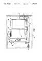
- FIG. 1is a side elevation of a stack handling system for loading stacks of sheets
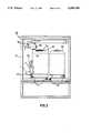
- FIG. 2is a side elevation of a stack handling system for unloading stacks of sheets
- FIG. 3is a side elevation of equipment for loading and unloading stacks of sheets
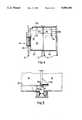
- FIG. 4is a top view of apparatus shown in FIG. 2;
- FIG. 5is a partial sectional view of adjacent stack receivers
- FIG. 6is a top view of a stack pusher with a preferred form of drive
- FIG. 7is a side sectional view of the pusher element of FIG. 6 showing the relationship to a stack receiver
- FIG. 8is a schematic illustration of another form of drive for the stack moving element.
- FIG. 9is a schematic illustration of a stack elevator.
- FIG. 1shows a stack loading apparatus 10 having a frame 11.
- a first or sheet feeding stack receiver 12is positioned within the frame and holds a first stack of paper sheets S1.
- a second or auxiliary stack receiver 14is positioned adjacent to and in side-by-side relationship to the first receiver 12.
- An auxiliary supply stack of paper S2is shown in the second receiver 14.
- the first receiver 12 and second receiver 14are mounted by suitable means, such as rails 15, to be movable into and out of the loader 10 in directions perpendicular to the plane of FIG. 1, for purposes of loading stacks of paper into the receivers.
- Individual sheets of paperare fed from the top of stack S1 by a sheet feeder 20 disposed adjacent the top of first receiver 12. As sheets are fed from the stack S1, the stack is raised by means of an elevator 16 so that the topmost sheet of paper in the stack S1 is positioned to be fed away from the stack by the sheet feeder 20. Designs of suitable feeders are known to those of skill in the art and further description is unnecessary for purposes of describing the invention. Sheets fed from the stack by the feeder 20 are fed into the paper handler 22 for subsequent processing, for example to be used as copy sheets in a xerographic reproduction process.
- the receiver 12also includes a drive motor 18 for raising and lowering the elevator 16.
- a drive motor 18for raising and lowering the elevator 16.
- the second receiver 14holds an auxiliary stack of paper S2, which is to be placed in the receiver 12 when the stack 1 is exhausted.
- a pusher 24 mounted on the frame 11is disposed adjacent the edge of the receiver 14 opposite to receiver 12. The pusher mechanism 24 will be described hereinafter in further detail.
- a stack unloading apparatushaving a frame 31 is illustrated.
- a first or stack forming receiver 32 and a second or stack unloading receiver 34are movable into and out of the stack unloader 30, as by rails 15, in directions perpendicular to the plane of FIG. 2. Such movement allows removal of stacks from the stack receivers 32 and 34 by an operator.
- Adjacent the top of the first receiver 32is a rotating sheet unloader 40.
- the sheet unloader 40receives sheets from sheet handling means including rollers 42, which sheets have been processed by upstream equipment and are ready for removal.
- the unloader 40delivers each sheet to the top of a stack S3 in the first receiver 32.
- the stack S3is supported on elevator 36, which is lowered progressively by the drive means 38 as additional sheets are repeatedly supplied to the stack S3.
- the stack S3is in position to be unloaded from the receiver 32.
- a stack pusher 44is mounted on the frame 31 adjacent the first receiver 32. The pusher 44 moves stack S3 laterally out of the first receiver 32 into the second receiver 34.
- FIG. 3illustrates a loading and unloading arrangement using the stack loader 10 of FIG. 1 and the stack unloader 30 of FIG. 2, which yields a combined stack loader and unloader 46.
- the stack unloader 30 shown in FIG. 3includes an additional tray 48 for receiving sheets which are not unloaded in the receiver 32. Because of the side-by-side arrangement of the respective receivers 12, 14 and 32, 34, the unloading unit 30 can be placed on top of the loading unit 10, or vice versa, thereby further minimizing floor space requirements.
- FIG. 4shows a top view of the stack unloader 30 of FIG. 2.
- This Figureshows the close side-by-side arrangement of the first receiver 32 and the second receiver 34.
- Each receiverhas a substantially U-shaped configuration.
- the receiversare arranged in mutual opposed relationship, to present two adjacent unobstructed edges 33 and 35, respectively.
- the elevator 36includes a guide 37 slidable on a slot 37a for positioning a stack on the elevator 36.
- the guide 37is movable in the slot 37a so that a plurality of sheet sizes can be accommodated.
- the second receiver 34includes a stop or guide 39 slidable in the slot 39a, also for the purpose of accommodating stacks of various sizes of paper.
- a similar arrangementis utilized for stack loader 10, with the exception that the pusher 24 is positioned adjacent second receiver 14.
- the first receiver 32includes an opening 84 in the side wall opposite the unobstructed edge 33.
- the pusher 44enters the opening 34 and pushes a stack of sheets on the elevator 36 of the first receiver 32 into the receiver 34 and then returns to the position shown in FIG. 4.
- FIG. 5shows an enlarged view of the positioning of first receiver 12 and second receiver 14 of a stack loader and illustrates the relative positioning of the stack support surface 50 of the second receiver 14 and the stack support surface 54 of the elevator 16.
- the surface 50 and surface 54include slightly chamfered or beveled surfaces 52 disposed along opposed, adjacent, unobstructed side edges 25 and 23 of the receivers 12 and 14, respectively.
- surface 50can be positioned slightly above surface 54 to facilitate transfer.
- the distance d between the receivers 12 and 14is such that a stack can be slid along the support surface 50 onto the surface 54 of elevator 16. This dimension generally is on the order of 1/4 inch.
- an auxilliary support surface or roller(not shown) can be positioned between the receivers to effect smooth transfer of the stack.
- This transfer systemrelies in part on the observation that a stack of paper sheets can be moved along a surface by a lateral pushing force applied against one side of the stack and the stack will maintain its form as it moves, under the influence of the weight of the paper sheets in the stack. The entire stack, including the bottom most sheet, can be moved in this fashion. In order to effect such movement, it is desirable to support the stack for movement on a substantially planar surfaces having a coefficient of friction which allows the stack to move without sticking of the bottom most sheet of the stack to the surfaces 50 and 54. Planar plain or coated metal surfaces and other smooth planar surfaces have been found suitable for this purpose. The foregoing design considerations are also used in the unloader 30 with respect to receivers 32 and 34.
- FIG. 6A form of stack pusher useful for both pusher 24 and pusher 44 is shown in FIG. 6.
- the guide 56has an upstanding vertical portion 58 and a substantially horizontal portion 60.
- the portion 58has a longitudinally extending slot 62 therein.
- a block 64is slidable in slot 62 and is guided by the vertical portion 58.
- the pusher elementincludes a toggle joint structure comprising a plurality of rigid links 66 pivoted together at their ends.
- One of the lefthand end linksis pivotably mounted on a fixed pivot plate 69 by a pin 68.
- the opposite lefthand end linkis pivoted by a pin 70 on the slidable block 64.
- a pusher plate 72is mounted thereon by means of a horizontally extending support plate 78 extending from one side of the vertical plate 72.
- One end of the plate 72is pivotably mounted, as by pin 74, to one of the righthand end links 66.
- the other end of the plate 72is mounted by a slidable pivot pin 76 to the other righthand end link 66.
- the pivot 76slides in the slot 80 formed in the support plate 78.
- the pusherincludes a rotatably mounted lead screw 82 driven by a suitable motor (not shown).
- the lead screwis received in a threaded bore of the slidable block 64 so that rotation of the lead screw 82 drives the block 64 transversely along the vertical portion 58 of the guide, in a direction governed by the direction of rotation of the lead screw 82.
- Movement of the slidable block 64causes the toggle links 66 to extend from or retract toward the guide 58.
- the slidable pivot 76allows the plate 72 to remain substantially parallel to the vertical portion 58, as the toggle drives the pusher plate 72, so that the plate moves the stack linearly.
- a gimbal mounting of the plate 72can be used to assure that no rotation or angular movement is imparted to the stack as it is pushed.
- the pusher plate 72is positioned adjacent an opening 84 in a side wall of the second receiver 14.
- the plateenters the receiver 14 through the opening 84 and engages a side surface of a stack of paper in the receiver 14.
- the drive of lead screw 82is reversed and the pusher element is retracted out of the second receiver 14.
- the pusher element 44 of the stack unloader 30operates substantially in a similar manner to unload a stack from the first receiver 32 into the second receiver 34.
- the respective second receiving means 14 and 34can be moved out of the loader or unloader.
- a new stack of papercan be placed in the second receiver 14 by the operator, while the feed from stack S1 in stack receiver 12 continues.
- a completed stackcan be removed from the second receiver 34 by the operator as a subsequent stack is formed in the first receiver 32.
- FIG. 8shows an alternate form of stack pusher having a plate 86 mounted on a depending support 88.
- a threaded collar 90received on a lead screw 92 rotatably supporting in a frame, such as frame 11 of loader 10.
- the plate 88is in retracted position adjacent one edge of the second receiver 14.
- Rotation of the lead screw 92causes movement of the plate 88 to the dotted line position to advance a stack of sheets from the second receiver 14 into the first receiver 12.
- Reverse rotation of the lead screw 92causes the plate 86 to return to the full line position adjacent an edge of the second receiver 14. Because the lead screw 92 overlies the receivers 12 and 14, little additional lateral space is needed for the drive, thereby minimizing floor space requirements.
- a rotatable drive shaft 94has a pair of belts or straps 96 fixed thereon.
- the lower ends of the straps 96are fixed to one edge of the elevator 16.
- the sides of the elevator 16are supported by cables 98a and 98b, the ends of which are fixed to portions of the receiver.
- Side edges of the elevator 16are supported on the cables 98 by grooved rollers 100.
- Rotation imparted to drive shaft 94 by motor 18 (FIG. 1) in one directioncauses the straps 96 to be wound on the shaft thereby raising the elevator 16. Rotation in the opposite direction allows the elevator 16 to be lowered.
- the opposed pulleys on each side of the elevator 16provide countermoments of equal magnitude which prevent tipping of the elevator and cause it to remain in a horizontal position.
- Other elevator arrangementsare also usable. One such arrangement would employ vertically extending lead screws on each side of the elevator 16 and positioned outside of the surface 54 to provide an unobstructed edge for stack transfer.
- An advantage of the disclosed loader/unloader designsis that controls are simplified.
- two detectors D1 and D2are provided.
- the elevator 16maintains contact of the topmost sheet of the stack S1 with the feeder 20.
- D1is preferably an optical sensor positioned to detect the presence of the topmost sheet of the stack by reflectance of light from the paper.
- the detector D1detects the absence of a sheet and allows the elevator 16 to descend to a stack receiving position, as shown in FIG. 5.
- the position of the elevator in its lowermost positionis detected by detector D2, the output signal enables drive of the motor for the pusher 24 (FIG.
- Detector D3which can be a mechanical switch or optical detector, senses the correct positioning of the stack on the elevator and enables start up of the elevator and commencement of the sheet feeding operation.
- the outputs of the detectors D1, D2 and D3are supplied to a suitable machine logic control system such as a microprocessor implemented control. Such controls are within the skill of a designer in this art and no further details regarding such systems are necessary.
- the operating sequenceis essentially reversed.
- detector D2detects this lowermost position and controls operation of the stack pusher 44 (FIG. 2).
- detector D1detects the upper position of the elevator and stops it in that position to receive sheets from the stacker element 40.
- the stack loader of FIG. 1 and stack unloader of FIG. 2have described the load-while-run and unload-while-run capabilities of the equipment. Namely, as the auxiliary stack is moved from the second receiver 14 or the stack to be unloaded is moved into the second receiver 34, the operator can withdraw the second receiver from the unit to, respectively, load a new auxiliary stack or unload a finished stack, while a paper feeding continues in the first receiver 12 or a paper stacking continues in the first receiver 32.
- the systemis also adaptable for use in a continuous run mode. That is, while the pusher mechanisms 24, 44 are being operated to transfer stacks, the feed of paper from or discharge of paper to auxiliary trays can continue.
- an auxiliary feed tray and suitable control systemcan be utilized to provide an uninterrupted supply of sheets to the reproduction apparatus.
- a tray systemsuch as shown in U.S. Pat. No. 4,008,957, the disclosure of which is incorporated herein by reference, can be utilized for such purposes.
- a systemsuch as shown in FIG. 3 can be utilized.
- the sheets fed from the apparatuscan be conveyed by belt 102 and suitable sheet handling equipment, including rollers 104, to dispense the sheets into tray 48.
- the feed of sheets to belt 102is terminated. Control systems for effecting such operation are within the skill of those in the art and would utilize, in part, the detectors D1 and D2 for control signals.
- the disclosed stack loader/unloader designprovides substantial advantages in terms of simplicity of construction and design.
- the drive systems for the stack pusherare compact and result in units which have low floor space requirements.
- the designscan accommodate two stacks of 2500 sheets of 81/2 ⁇ 11, A4, or A3 paper and thus provide high volume capacity and lessen down time and operator attendance requirements.
- the unitalso has the added flexibility of use for feeding large sheets, which would be supported on both the first and second receivers. In this latter case, a suitable elevator might be used in the second receiver or the supporting surface in the second receiver may be locked to the elevator so that the elevator and support surface move together.
Landscapes
- Engineering & Computer Science (AREA)
- Mechanical Engineering (AREA)
- Sheets, Magazines, And Separation Thereof (AREA)
Abstract
Description
Claims (20)
Priority Applications (1)
| Application Number | Priority Date | Filing Date | Title |
|---|---|---|---|
| US07/552,052US5096181A (en) | 1990-07-13 | 1990-07-13 | Sheet feeding and delivering apparatus having stack replenishment and removal for allowing continuous operation |
Applications Claiming Priority (1)
| Application Number | Priority Date | Filing Date | Title |
|---|---|---|---|
| US07/552,052US5096181A (en) | 1990-07-13 | 1990-07-13 | Sheet feeding and delivering apparatus having stack replenishment and removal for allowing continuous operation |
Publications (1)
| Publication Number | Publication Date |
|---|---|
| US5096181Atrue US5096181A (en) | 1992-03-17 |
Family
ID=24203749
Family Applications (1)
| Application Number | Title | Priority Date | Filing Date |
|---|---|---|---|
| US07/552,052Expired - LifetimeUS5096181A (en) | 1990-07-13 | 1990-07-13 | Sheet feeding and delivering apparatus having stack replenishment and removal for allowing continuous operation |
Country Status (1)
| Country | Link |
|---|---|
| US (1) | US5096181A (en) |
Cited By (19)
| Publication number | Priority date | Publication date | Assignee | Title |
|---|---|---|---|---|
| US5157448A (en)* | 1992-04-16 | 1992-10-20 | Xerox Corporation | Automatic copier or printer paper tray lock |
| US5222860A (en)* | 1992-06-25 | 1993-06-29 | Xerox Corporation | Floor space efficient printer with high load and unload capability |
| US5335903A (en)* | 1992-11-27 | 1994-08-09 | Xerox Corporation | High capacity dual tray variable sheet size sheet feeder |
| US5374045A (en)* | 1993-09-27 | 1994-12-20 | Xerox Corporation | Printing apparatus with deferred jam clearance |
| US5573234A (en)* | 1994-11-23 | 1996-11-12 | Xerox Corporation | Dual mode sheet feeder |
| US6099452A (en)* | 1995-03-01 | 2000-08-08 | Moore Business Forms, Inc. | Forms stacker |
| US20040079466A1 (en)* | 2002-10-23 | 2004-04-29 | Amesbury Group Inc. | Pile weatherstripping manufacturing apparatus and method |
| US20050047826A1 (en)* | 2003-08-26 | 2005-03-03 | Yoshiharu Yoneda | Sheet feeding device and image forming apparatus |
| US20060068156A1 (en)* | 2004-09-29 | 2006-03-30 | Linear Limited | Pile weatherstrip and the manufacture thereof |
| US20070096386A1 (en)* | 2005-10-31 | 2007-05-03 | Brother Kogyo Kabushiki Kaisha | Printer with sheet returning mechanism |
| US20080054558A1 (en)* | 2006-09-06 | 2008-03-06 | Canon Kabushiki Kaisha | Sheet-stacking apparatus and image-forming apparatus |
| US20080277867A1 (en)* | 2007-05-08 | 2008-11-13 | Canon Kabushiki Kaisha | Sheet stacking apparatus and sheet stacking control method |
| US20090001650A1 (en)* | 2007-06-28 | 2009-01-01 | Canon Kabushiki Kaisha | Sheet stacking apparatus and method of controlling the sheet stacking apparatus |
| US20090072467A1 (en)* | 2007-09-13 | 2009-03-19 | Kabushiki Kaisha Toashiba | Sheet Conveying Apparatus |
| US20100156043A1 (en)* | 2008-12-19 | 2010-06-24 | Canon Kabushiki Kaisha | Sheet processing apparatus, control method of sheet processing apparatus, and storage medium |
| US20110148029A1 (en)* | 2009-12-18 | 2011-06-23 | Connell Brian P | Dual-stack document storage bin for use in a self-service bunch document depositing terminal |
| US20150210499A1 (en)* | 2009-03-26 | 2015-07-30 | Fuji Xerox Co., Ltd. | Image forming apparatus and recording medium stacking apparatus |
| US20170066611A1 (en)* | 2015-09-08 | 2017-03-09 | Canon Kabushiki Kaisha | Sheet feeding apparatus having containing area for feeding sheet and containing area for replenishing sheet, and image forming apparatus |
| US20170066612A1 (en)* | 2015-09-08 | 2017-03-09 | Canon Kabushiki Kaisha | Sheet feeding apparatus and image forming apparatus |
Citations (21)
| Publication number | Priority date | Publication date | Assignee | Title |
|---|---|---|---|---|
| US2108613A (en)* | 1936-06-22 | 1938-02-15 | Stokes & Smith Co | Adhesive applying mechanism |
| US2921788A (en)* | 1955-02-16 | 1960-01-19 | James C Lawrence | Single sheet feeders |
| US3211449A (en)* | 1957-12-30 | 1965-10-12 | Kimberly Clark Co | Papermaking machine |
| US3288463A (en)* | 1964-01-29 | 1966-11-29 | Nat Can Corp | Auxiliary stack holder |
| US3369805A (en)* | 1967-02-23 | 1968-02-20 | Miner Denver Inc | Apparatus for loading wrappers into a bundle underwrapper |
| US3415510A (en)* | 1967-05-29 | 1968-12-10 | Xerox Corp | Auxiliary sheet feeder |
| US3843115A (en)* | 1973-11-23 | 1974-10-22 | Eastman Kodak Co | Elevator apparatus |
| US3975011A (en)* | 1975-02-10 | 1976-08-17 | Georg Spiess Gmbh | Stack changer in continuously operated sheet feeding machines |
| US4008957A (en)* | 1975-05-27 | 1977-02-22 | Xerox Corporation | Reproduction machine control |
| US4046370A (en)* | 1975-07-25 | 1977-09-06 | Anpa Research Institute | Method and apparatus for inserting a bundle of newspaper inserts into a hopper |
| US4153242A (en)* | 1976-10-29 | 1979-05-08 | Ricoh Company, Ltd. | Sheet feed apparatus |
| US4174831A (en)* | 1976-08-18 | 1979-11-20 | Georg Spiess Gmbh | Device for inserting a new stack of sheets in feeding position without interruption of sheet-feeding mechanism operation |
| US4418907A (en)* | 1981-09-16 | 1983-12-06 | Burroughs Corporation | Automatic reloader-elevator for cut sheet printing apparatus |
| US4434912A (en)* | 1981-08-13 | 1984-03-06 | Larson Charles L | Accumulator for veneer feeder |
| US4452440A (en)* | 1981-08-28 | 1984-06-05 | Emf Corporation | Paper feeding apparatus and cart |
| US4484734A (en)* | 1981-07-21 | 1984-11-27 | Mita Industrial Company Limited | Copy paper feeding device for a copying apparatus |
| US4525063A (en)* | 1982-12-01 | 1985-06-25 | Develop Dr. Eisbein Gmbh & Co. | Paper holder for a photocopying machine |
| JPS60171947A (en)* | 1984-02-15 | 1985-09-05 | Fuji Xerox Co Ltd | Draw-out device of sheet containing means |
| JPS60204527A (en)* | 1984-03-28 | 1985-10-16 | Toppan Printing Co Ltd | Method of mounting printing paper |
| US4703924A (en)* | 1985-02-09 | 1987-11-03 | George Spiess Gmbh | Sheet feeding apparatus with mechanical pile retraction |
| US4801135A (en)* | 1987-06-19 | 1989-01-31 | Xerox Corporation | Sheet handling apparatus |
- 1990
- 1990-07-13USUS07/552,052patent/US5096181A/ennot_activeExpired - Lifetime
Patent Citations (21)
| Publication number | Priority date | Publication date | Assignee | Title |
|---|---|---|---|---|
| US2108613A (en)* | 1936-06-22 | 1938-02-15 | Stokes & Smith Co | Adhesive applying mechanism |
| US2921788A (en)* | 1955-02-16 | 1960-01-19 | James C Lawrence | Single sheet feeders |
| US3211449A (en)* | 1957-12-30 | 1965-10-12 | Kimberly Clark Co | Papermaking machine |
| US3288463A (en)* | 1964-01-29 | 1966-11-29 | Nat Can Corp | Auxiliary stack holder |
| US3369805A (en)* | 1967-02-23 | 1968-02-20 | Miner Denver Inc | Apparatus for loading wrappers into a bundle underwrapper |
| US3415510A (en)* | 1967-05-29 | 1968-12-10 | Xerox Corp | Auxiliary sheet feeder |
| US3843115A (en)* | 1973-11-23 | 1974-10-22 | Eastman Kodak Co | Elevator apparatus |
| US3975011A (en)* | 1975-02-10 | 1976-08-17 | Georg Spiess Gmbh | Stack changer in continuously operated sheet feeding machines |
| US4008957A (en)* | 1975-05-27 | 1977-02-22 | Xerox Corporation | Reproduction machine control |
| US4046370A (en)* | 1975-07-25 | 1977-09-06 | Anpa Research Institute | Method and apparatus for inserting a bundle of newspaper inserts into a hopper |
| US4174831A (en)* | 1976-08-18 | 1979-11-20 | Georg Spiess Gmbh | Device for inserting a new stack of sheets in feeding position without interruption of sheet-feeding mechanism operation |
| US4153242A (en)* | 1976-10-29 | 1979-05-08 | Ricoh Company, Ltd. | Sheet feed apparatus |
| US4484734A (en)* | 1981-07-21 | 1984-11-27 | Mita Industrial Company Limited | Copy paper feeding device for a copying apparatus |
| US4434912A (en)* | 1981-08-13 | 1984-03-06 | Larson Charles L | Accumulator for veneer feeder |
| US4452440A (en)* | 1981-08-28 | 1984-06-05 | Emf Corporation | Paper feeding apparatus and cart |
| US4418907A (en)* | 1981-09-16 | 1983-12-06 | Burroughs Corporation | Automatic reloader-elevator for cut sheet printing apparatus |
| US4525063A (en)* | 1982-12-01 | 1985-06-25 | Develop Dr. Eisbein Gmbh & Co. | Paper holder for a photocopying machine |
| JPS60171947A (en)* | 1984-02-15 | 1985-09-05 | Fuji Xerox Co Ltd | Draw-out device of sheet containing means |
| JPS60204527A (en)* | 1984-03-28 | 1985-10-16 | Toppan Printing Co Ltd | Method of mounting printing paper |
| US4703924A (en)* | 1985-02-09 | 1987-11-03 | George Spiess Gmbh | Sheet feeding apparatus with mechanical pile retraction |
| US4801135A (en)* | 1987-06-19 | 1989-01-31 | Xerox Corporation | Sheet handling apparatus |
Cited By (35)
| Publication number | Priority date | Publication date | Assignee | Title |
|---|---|---|---|---|
| US5157448A (en)* | 1992-04-16 | 1992-10-20 | Xerox Corporation | Automatic copier or printer paper tray lock |
| US5222860A (en)* | 1992-06-25 | 1993-06-29 | Xerox Corporation | Floor space efficient printer with high load and unload capability |
| US5335903A (en)* | 1992-11-27 | 1994-08-09 | Xerox Corporation | High capacity dual tray variable sheet size sheet feeder |
| US5374045A (en)* | 1993-09-27 | 1994-12-20 | Xerox Corporation | Printing apparatus with deferred jam clearance |
| US5573234A (en)* | 1994-11-23 | 1996-11-12 | Xerox Corporation | Dual mode sheet feeder |
| US6099452A (en)* | 1995-03-01 | 2000-08-08 | Moore Business Forms, Inc. | Forms stacker |
| US7419555B2 (en) | 2002-10-23 | 2008-09-02 | Amesbury Group, Inc. | Pile weatherstripping manufacturing apparatus and method |
| US20040079466A1 (en)* | 2002-10-23 | 2004-04-29 | Amesbury Group Inc. | Pile weatherstripping manufacturing apparatus and method |
| US6974512B2 (en) | 2002-10-23 | 2005-12-13 | Amesbury Group, Inc. | Pile weatherstripping manufacturing apparatus and method |
| US20060051553A1 (en)* | 2002-10-23 | 2006-03-09 | Amesbury Group, Inc. | Pile weatherstripping manfuacturing apparatus and method |
| US20050047826A1 (en)* | 2003-08-26 | 2005-03-03 | Yoshiharu Yoneda | Sheet feeding device and image forming apparatus |
| US7167663B2 (en)* | 2003-08-26 | 2007-01-23 | Sharp Kabushiki Kaisha | Sheet feeding device and image forming apparatus |
| US20060068156A1 (en)* | 2004-09-29 | 2006-03-30 | Linear Limited | Pile weatherstrip and the manufacture thereof |
| US20070096386A1 (en)* | 2005-10-31 | 2007-05-03 | Brother Kogyo Kabushiki Kaisha | Printer with sheet returning mechanism |
| US20080054558A1 (en)* | 2006-09-06 | 2008-03-06 | Canon Kabushiki Kaisha | Sheet-stacking apparatus and image-forming apparatus |
| US8485525B2 (en)* | 2006-09-06 | 2013-07-16 | Canon Kabushiki Kaisha | Sheet-stacking apparatus and image-forming apparatus |
| US7597324B2 (en)* | 2006-09-06 | 2009-10-06 | Canon Kabushiki Kaisha | Sheet-stacking apparatus and image-forming apparatus |
| US20090309300A1 (en)* | 2006-09-06 | 2009-12-17 | Canon Kabushiki Kaisha | Sheet-stacking apparatus and image-forming apparatus |
| US20080277867A1 (en)* | 2007-05-08 | 2008-11-13 | Canon Kabushiki Kaisha | Sheet stacking apparatus and sheet stacking control method |
| US8376360B2 (en)* | 2007-05-08 | 2013-02-19 | Canon Kabushiki Kaisha | Sheet stacking apparatus and sheet stacking control method |
| US20090001650A1 (en)* | 2007-06-28 | 2009-01-01 | Canon Kabushiki Kaisha | Sheet stacking apparatus and method of controlling the sheet stacking apparatus |
| US8657286B2 (en)* | 2007-06-28 | 2014-02-25 | Canon Kabushiki Kaisha | Sheet stacking apparatus and method of controlling the sheet stacking apparatus |
| US20090072467A1 (en)* | 2007-09-13 | 2009-03-19 | Kabushiki Kaisha Toashiba | Sheet Conveying Apparatus |
| US20110074095A1 (en)* | 2007-09-13 | 2011-03-31 | Kabushiki Kaisha Toshiba | Sheet conveying apparatus |
| US7866654B2 (en)* | 2007-09-13 | 2011-01-11 | Kabushiki Kaisha Toshiba | Sheet conveying apparatus |
| US8348274B2 (en)* | 2008-12-19 | 2013-01-08 | Canon Kabushiki Kaisha | Sheet processing apparatus, control method of sheet processing apparatus, and storage medium |
| US20100156043A1 (en)* | 2008-12-19 | 2010-06-24 | Canon Kabushiki Kaisha | Sheet processing apparatus, control method of sheet processing apparatus, and storage medium |
| US9394134B2 (en)* | 2009-03-26 | 2016-07-19 | Fuji Xerox Co., Ltd. | Image forming apparatus and recording medium stacking apparatus |
| US20150210499A1 (en)* | 2009-03-26 | 2015-07-30 | Fuji Xerox Co., Ltd. | Image forming apparatus and recording medium stacking apparatus |
| US8066273B2 (en)* | 2009-12-18 | 2011-11-29 | Ncr Corporation | Dual-stack document storage bin for use in a self-service bunch document depositing terminal |
| US20110148029A1 (en)* | 2009-12-18 | 2011-06-23 | Connell Brian P | Dual-stack document storage bin for use in a self-service bunch document depositing terminal |
| US20170066611A1 (en)* | 2015-09-08 | 2017-03-09 | Canon Kabushiki Kaisha | Sheet feeding apparatus having containing area for feeding sheet and containing area for replenishing sheet, and image forming apparatus |
| US20170066612A1 (en)* | 2015-09-08 | 2017-03-09 | Canon Kabushiki Kaisha | Sheet feeding apparatus and image forming apparatus |
| US9963313B2 (en)* | 2015-09-08 | 2018-05-08 | Canon Kabushiki Kaisha | Sheet feeding apparatus having containing area for feeding sheet and containing area for replenishing sheet, and image forming apparatus |
| US9969578B2 (en)* | 2015-09-08 | 2018-05-15 | Canon Kabushiki Kaisha | Sheet feeding apparatus and image forming apparatus |
Similar Documents
| Publication | Publication Date | Title |
|---|---|---|
| US5096181A (en) | Sheet feeding and delivering apparatus having stack replenishment and removal for allowing continuous operation | |
| US3776544A (en) | Automatic loading apparatus | |
| US5102112A (en) | Paper feeding device for image forming equipment | |
| EP0697627B1 (en) | Method and apparatus for an external media buffer | |
| US4538799A (en) | Sheet feeding apparatus | |
| EP0532318A1 (en) | Sheet stacking apparatus | |
| US5205548A (en) | Automatic document sheet conveyance device | |
| JP2635895B2 (en) | 2 corner sheet stacking device | |
| US5166736A (en) | Electrophotographic printing apparatus with pivotable paper buffer and pivotable guide member | |
| GB2342091A (en) | Sheet feed assembly | |
| US4378110A (en) | Continuous paper sorting machine | |
| KR102826610B1 (en) | Paper inversion loading apparatus and combining system for corrugated cardboard having the apparatus | |
| JPH02152845A (en) | paper conveyance device | |
| JPS6028670A (en) | Double face copying machine | |
| JPS60197542A (en) | Transfer paper supply device | |
| JPS58135041A (en) | Paper feeding unit | |
| JPH07104527A (en) | Image forming apparatus with double-sided device | |
| JPH0494369A (en) | paper stacking device | |
| JPH0632921Y2 (en) | Collating device with guidance | |
| JPH0583470B2 (en) | ||
| JPH0733240Y2 (en) | Paper feeder | |
| JP2916343B2 (en) | Sheet dispenser | |
| JPH0772030B2 (en) | Transfer paper supply device | |
| JPS59227659A (en) | Sheet assorting apparatus | |
| JPH0478547B2 (en) |
Legal Events
| Date | Code | Title | Description |
|---|---|---|---|
| AS | Assignment | Owner name:XEROX CORPORATION, A CORP. OF NY, CONNECTICUT Free format text:ASSIGNMENT OF ASSIGNORS INTEREST.;ASSIGNORS:MENON, SUKUMARAN K.;SIEGL, WILLIAM F.;REEL/FRAME:005443/0329 Effective date:19900910 Owner name:XEROX CORPORATION, A CORP. OF NY, CONNECTICUT Free format text:ASSIGNMENT OF ASSIGNORS INTEREST.;ASSIGNOR:SILVERBERG, MORTON;REEL/FRAME:005443/0331 Effective date:19900830 | |
| STCF | Information on status: patent grant | Free format text:PATENTED CASE | |
| FEPP | Fee payment procedure | Free format text:PAYOR NUMBER ASSIGNED (ORIGINAL EVENT CODE: ASPN); ENTITY STATUS OF PATENT OWNER: LARGE ENTITY | |
| FPAY | Fee payment | Year of fee payment:4 | |
| FPAY | Fee payment | Year of fee payment:8 | |
| AS | Assignment | Owner name:BANK ONE, NA, AS ADMINISTRATIVE AGENT, ILLINOIS Free format text:SECURITY INTEREST;ASSIGNOR:XEROX CORPORATION;REEL/FRAME:013153/0001 Effective date:20020621 | |
| FPAY | Fee payment | Year of fee payment:12 | |
| AS | Assignment | Owner name:JPMORGAN CHASE BANK, AS COLLATERAL AGENT, TEXAS Free format text:SECURITY AGREEMENT;ASSIGNOR:XEROX CORPORATION;REEL/FRAME:015134/0476 Effective date:20030625 Owner name:JPMORGAN CHASE BANK, AS COLLATERAL AGENT,TEXAS Free format text:SECURITY AGREEMENT;ASSIGNOR:XEROX CORPORATION;REEL/FRAME:015134/0476 Effective date:20030625 | |
| AS | Assignment | Owner name:XEROX CORPORATION, CONNECTICUT Free format text:RELEASE BY SECURED PARTY;ASSIGNOR:JPMORGAN CHASE BANK, N.A. AS SUCCESSOR-IN-INTEREST ADMINISTRATIVE AGENT AND COLLATERAL AGENT TO JPMORGAN CHASE BANK;REEL/FRAME:066728/0193 Effective date:20220822 |