US5095937A - Two stage automatic shut off valve - Google Patents
Two stage automatic shut off valveDownload PDFInfo
- Publication number
- US5095937A US5095937AUS07/647,282US64728291AUS5095937AUS 5095937 AUS5095937 AUS 5095937AUS 64728291 AUS64728291 AUS 64728291AUS 5095937 AUS5095937 AUS 5095937A
- Authority
- US
- United States
- Prior art keywords
- valve
- float
- tank
- housing
- level
- Prior art date
- Legal status (The legal status is an assumption and is not a legal conclusion. Google has not performed a legal analysis and makes no representation as to the accuracy of the status listed.)
- Expired - Lifetime
Links
- 239000007788liquidSubstances0.000claimsdescription33
- 230000008878couplingEffects0.000claimsdescription22
- 238000010168coupling processMethods0.000claimsdescription22
- 238000005859coupling reactionMethods0.000claimsdescription22
- 230000002829reductive effectEffects0.000claimsdescription16
- 230000000670limiting effectEffects0.000claimsdescription4
- 230000000284resting effectEffects0.000claimsdescription3
- 230000000903blocking effectEffects0.000claims2
- 238000007599dischargingMethods0.000claims1
- 239000012530fluidSubstances0.000claims1
- 230000002265preventionEffects0.000claims1
- 239000000446fuelSubstances0.000abstractdescription101
- 230000002028prematureEffects0.000abstractdescription5
- 238000011084recoveryMethods0.000abstractdescription5
- 230000007246mechanismEffects0.000description16
- XLYOFNOQVPJJNP-UHFFFAOYSA-NwaterSubstancesOXLYOFNOQVPJJNP-UHFFFAOYSA-N0.000description5
- 238000010586diagramMethods0.000description4
- 230000000694effectsEffects0.000description4
- 230000004048modificationEffects0.000description3
- 238000012986modificationMethods0.000description3
- 230000036961partial effectEffects0.000description3
- 230000003068static effectEffects0.000description3
- 230000005484gravityEffects0.000description2
- 230000009467reductionEffects0.000description2
- 230000000630rising effectEffects0.000description2
- 230000009471actionEffects0.000description1
- 230000033228biological regulationEffects0.000description1
- 238000010276constructionMethods0.000description1
- 230000007423decreaseEffects0.000description1
- 238000006073displacement reactionMethods0.000description1
- 230000003028elevating effectEffects0.000description1
- 230000007613environmental effectEffects0.000description1
- 238000000034methodMethods0.000description1
- 238000007789sealingMethods0.000description1
Images


Classifications
- B—PERFORMING OPERATIONS; TRANSPORTING
- B65—CONVEYING; PACKING; STORING; HANDLING THIN OR FILAMENTARY MATERIAL
- B65D—CONTAINERS FOR STORAGE OR TRANSPORT OF ARTICLES OR MATERIALS, e.g. BAGS, BARRELS, BOTTLES, BOXES, CANS, CARTONS, CRATES, DRUMS, JARS, TANKS, HOPPERS, FORWARDING CONTAINERS; ACCESSORIES, CLOSURES, OR FITTINGS THEREFOR; PACKAGING ELEMENTS; PACKAGES
- B65D90/00—Component parts, details or accessories for large containers
- B65D90/22—Safety features
- B65D90/26—Overfill prevention
- Y—GENERAL TAGGING OF NEW TECHNOLOGICAL DEVELOPMENTS; GENERAL TAGGING OF CROSS-SECTIONAL TECHNOLOGIES SPANNING OVER SEVERAL SECTIONS OF THE IPC; TECHNICAL SUBJECTS COVERED BY FORMER USPC CROSS-REFERENCE ART COLLECTIONS [XRACs] AND DIGESTS
- Y10—TECHNICAL SUBJECTS COVERED BY FORMER USPC
- Y10T—TECHNICAL SUBJECTS COVERED BY FORMER US CLASSIFICATION
- Y10T137/00—Fluid handling
- Y10T137/5762—With leakage or drip collecting
- Y—GENERAL TAGGING OF NEW TECHNOLOGICAL DEVELOPMENTS; GENERAL TAGGING OF CROSS-SECTIONAL TECHNOLOGIES SPANNING OVER SEVERAL SECTIONS OF THE IPC; TECHNICAL SUBJECTS COVERED BY FORMER USPC CROSS-REFERENCE ART COLLECTIONS [XRACs] AND DIGESTS
- Y10—TECHNICAL SUBJECTS COVERED BY FORMER USPC
- Y10T—TECHNICAL SUBJECTS COVERED BY FORMER US CLASSIFICATION
- Y10T137/00—Fluid handling
- Y10T137/7287—Liquid level responsive or maintaining systems
- Y10T137/7329—With supplemental or safety closing means or bias
- Y—GENERAL TAGGING OF NEW TECHNOLOGICAL DEVELOPMENTS; GENERAL TAGGING OF CROSS-SECTIONAL TECHNOLOGIES SPANNING OVER SEVERAL SECTIONS OF THE IPC; TECHNICAL SUBJECTS COVERED BY FORMER USPC CROSS-REFERENCE ART COLLECTIONS [XRACs] AND DIGESTS
- Y10—TECHNICAL SUBJECTS COVERED BY FORMER USPC
- Y10T—TECHNICAL SUBJECTS COVERED BY FORMER US CLASSIFICATION
- Y10T137/00—Fluid handling
- Y10T137/7287—Liquid level responsive or maintaining systems
- Y10T137/7358—By float controlled valve
- Y10T137/7404—Plural floats
- Y—GENERAL TAGGING OF NEW TECHNOLOGICAL DEVELOPMENTS; GENERAL TAGGING OF CROSS-SECTIONAL TECHNOLOGIES SPANNING OVER SEVERAL SECTIONS OF THE IPC; TECHNICAL SUBJECTS COVERED BY FORMER USPC CROSS-REFERENCE ART COLLECTIONS [XRACs] AND DIGESTS
- Y10—TECHNICAL SUBJECTS COVERED BY FORMER USPC
- Y10T—TECHNICAL SUBJECTS COVERED BY FORMER US CLASSIFICATION
- Y10T137/00—Fluid handling
- Y10T137/7287—Liquid level responsive or maintaining systems
- Y10T137/7358—By float controlled valve
- Y10T137/7423—Rectilinearly traveling float
- Y10T137/7426—Float co-axial with valve or port
- Y10T137/7433—Float surrounds inlet pipe
- Y—GENERAL TAGGING OF NEW TECHNOLOGICAL DEVELOPMENTS; GENERAL TAGGING OF CROSS-SECTIONAL TECHNOLOGIES SPANNING OVER SEVERAL SECTIONS OF THE IPC; TECHNICAL SUBJECTS COVERED BY FORMER USPC CROSS-REFERENCE ART COLLECTIONS [XRACs] AND DIGESTS
- Y10—TECHNICAL SUBJECTS COVERED BY FORMER USPC
- Y10T—TECHNICAL SUBJECTS COVERED BY FORMER US CLASSIFICATION
- Y10T137/00—Fluid handling
- Y10T137/7287—Liquid level responsive or maintaining systems
- Y10T137/7358—By float controlled valve
- Y10T137/7439—Float arm operated valve
- Y10T137/7485—Pivoted valve
Definitions
- the present inventionis directed to a float actuated shutoff valve employed to prevent overfilling of a liquid storage tank, such as an underground fuel storage tank, for example.
- the typical underground fuel storage tank utilized in service stations throughout the United Stateshas a capacity of several thousand gallons and is normally buried beneath the service station apron at a depth below the frost line.
- a fill pipeextends upwardly from the top of the tank to a supply hose coupling accessible within a relatively shallow manhole.
- a supply hose from the tank truckis coupled to the fill pipe, and fuel is fed by gravity from the tank truck through the supply hose and fill pipe into the tank.
- the head space of the tankis normally provided with an atmospheric vent. In almost all cases, there is no gauge for indicating the state of fullness of the tank.
- the fuel delivery manis supposed to measure the amount of fuel in the tank prior to filling by inserting a dip stick through the fill pipe, and is prohibited from connecting the storage tank to a fuel compartment of the tank truck which has more fuel than can be placed in the storage tank without overfilling the storage tank.
- this procedureis not always followed, and overfilling of the storage tank and the resultant spillage of fuel is a common occurrence.
- float actuated valveshave been employed in increasing numbers to automatically close off or block the fill pipe when the level of fuel within the storage tank rises to a level indicating the tank is nearly full.
- the float actuated valves of the prior arttypically employ a pivoted flapper valve in which the valve flapper or head is withdrawn into a recess at one side of the fuel inlet passage to the tank during filling and coupled to a float disposed within the tank to be pivoted outwardly into the flow path of the incoming fuel when the level within the storage tank rises to the selected level.
- the flapperis then driven to its seat with considerable force by the downwardly flowing fuel, resulting in a substantial water hammer effect when the rate of flow of fuel through the supply hose and fill pipe coupling is reduced from a typical rate of 400 gallons per minute to zero almost instantaneously.
- this water hammer effectis minimized by employing a two-stage valve in which a first valve flapper is float actuated when the tank is approximately 90% full to close and partially, but not completely, block the incoming flow passage. With the passage partially blocked by closure of the first flapper, the rate of flow of fuel into the tank is substantially reduced, and the less severe water hammer generated by the partial closure can be observed by the delivery man who can, if he is so motivated, shut off the flow of fuel at the tank truck at a time when the storage tank has ample capacity to receive the 25 or 30 gallons remaining in the tank truck hose downstream of the tank truck shutoff valve.
- the flapper valvesare mounted within a valve housing at the upper end of a drop tube projecting downwardly through the storage tank fill pipe into the tank.
- the supply hose coupling to which the tank truck supply hose is coupled during a filling operationis mounted at the top of the drop tube.
- the most convenient way of accomplishing this vapor recoveryis to employ an arrangement in which fuel is conducted into the storage tank via the drop tube which is loosely received within the storage tank fill pipe, and vapor passing upwardly through the space between the outside of the fuel carrying drop tube and the inside of the fill pipe is passed through the supply coupling to the tank truck hose coupling, from which it is conducted back to the tank truck.
- Thisis accomplished by mounting an adapter at the top of the storage tank fill pipe which has an enlarged central passage opening into the interior of the fill pipe and co-axially mounting, within the enlarged central passage of the adapter, the smaller diameter drop tube.
- the hose coupling on the tank truck hosefits around the outer side of the adapter, and the fuel flow passage through the hose coupling is sealed to the upper end of the drop tube when the hose coupling is mated to the fill pipe supply coupling. Passages through the hose pipe coupling conduct vapor from the fill pipe to a vapor transfer hose. With such an arrangement, it is impractical to mount the two-stage valve of parent application Ser. No. 07/534,442 at the top of the fill pipe, and the present invention is directed to a solution for that problem.
- valve flappers of parent application Ser. No. 07/534,442are, as is typical with the prior art, mounted for pivotal movement about a horizontal axis, and when in their open position project vertically upwardly from the pivot axis.
- the flapperWhen in its open position, the flapper is located within a recess in the side of the flow passage so that the main stream of downwardly flowing incoming fuel passes in front of the flapper. Only a slight movement of the flapper from its open position will swing the top edge of the flapper into the main stream of the fuel, and once this occurs, the fuel stream overrides the flapper actuating mechanism and forcibly drives the flapper to its closed position. Because at least some of the incoming fuel will flow into the recess behind the flapper there is at least some possibility that this last flow could shift the flapper forwardly from its open position enough to cause a premature closure of the flapper.
- the present inventionprovides a float actuated locking pin arrangement which will prevent such premature closure.
- the shutoff valve of the present inventionis designed to be used in conjunction with either a standard fuel storage tank vented at a location remote from the fuel inlet or with an underground fuel storage tank having a so-called co-axial vapor recovery system utilizing certain portions of the shutoff valve assembly.
- a co-axial vapor recovery systeman elongate drop tube is passed freely downwardly through the conventional storage tank fill pipe, and the supply hose coupling at the upper end of the fill pipe and the drop tube define co-axial passages adapted to be connected to a co-axial elbow or tank truck supply hose coupling.
- Fuel from the tank truckpasses downwardly through the interior of the drop tube, while fuel vapor expelled from the storage tank by the incoming fuel passes upwardly through the space between the fill pipe and drop tube into a vapor passage in the elbow connected to a vapor receiving compartment in the tank truck.
- the drop tubeconstitutes the fuel inlet to a two-stage shutoff valve whose housing is mounted at the lower end of the drop tube to be located within the interior of the storage tank well below the top of the tank.
- a fuel flow passageextends vertically from the drop tube downwardly through the valve housing and is formed with an upwardly facing valve seat extending around the upper end of a reduced diameter section of the flow passage.
- a first and a second plate-like valve flapperare located at opposite sides of the passage immediately above the valve seat for pivotal movement between respective open positions where the flappers project upwardly from the valve seat and are located in recesses at opposite sides of the passage out of the main path of flow of fuel downwardly through the valve housing.
- Each flapperis formed with a crank which is pivotally connected to the lower end of respective actuating rods.
- the actuating rodsproject upwardly freely through vertical bores in the housing.
- the rod from the first flapperis pivotally connected at its upper end to a first or lower hollow tubular float slidably received upon the drop tube above the housing.
- the actuating rod of the second valve flapperpasses upwardly from the housing freely through a vertical bore through the first float and is pivotally secured at its upper end to a second or upper hollow tubular float slidably received upon the drop tube above the first float.
- the first floatDuring filling of the tank, as the level of fuel rises above the valve housing, the first float becomes buoyed upwardly and upward movement of the first float causes its actuating rod to pivot the first valve flapper from its open position outwardly into the path of downwardly flowing fuel which promptly drives the first flapper to a valve closed position.
- the first valve flapperWhen in its closed position, the first valve flapper lies across a major portion of the reduced diameter section of the flow passage and, when closed, substantially reduces, but does not completely terminate, the flow of fuel downwardly through the valve.
- the second or upper floatis buoyed upwardly, and its actuating rod similarly swings the second valve flapper into the path of flow of fuel which drives the second flapper to its valve closed position upon the valve seat.
- both flappersare in their closed position, the reduced diameter section of the passage is completely blocked, and no further fuel can flow into the tank.
- the head of fuel holding the flappers in their closed positiondecreases, and at some point after the fuel no longer buoys up the upper of the two floats, the unbuoyed weight of the upper float will be sufficient to overcome the head of fuel holding the smaller or second valve flapper in its closed position, and open the second valve flapper to drain the trapped fuel from the drop tube into the storage tank. Further dropping of the fuel level within the tank will result in downward movement of the first or lower float, and this downward movement will restore the first valve lapper to its open position.
- each flapperis provided with a float actuated locking pin in the form of an elongate vertical rod which passes freely through a vertical bore in the top of the housing and a vertical bore through the float which actuates the flapper
- a stop collar on the locking rodrests on the top of the float when the float is in its lowered unbuoyed position to locate the lower end of the locking rod in front of the opened flapper to constitute a positive stop preventing movement of the flapper from its open position.
- a pivoted rod gripper controlled by a stop collar on the associated actuating rodis employed to lock the locking pin in an inoperative position until after the float has been lowered sufficiently to return the flapper to its open position, at which time the gripper releases the locking rod.
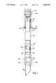
- FIG. 1is a side elevational view of a valve assembly embodying the present invention mounted within a partially indicated storage tank, with certain parts broken away, shown in section, or indicated in broken line;
- FIG. 2is a detailed cross sectional view taken on a vertical plane showing a portion of the lower end of the drop tube and valve housing of the valve assembly of FIG. 1;
- FIG. 2Ais a detailed cross sectional view of a portion of the valve housing, taken on line 2A--2A of FIG. 2;
- FIG. 3is a detailed cross sectional view taken on line 3--3 of FIG. 2;
- FIGS. 4, 5 and 6are schematic diagrams of the assembly of FIG. 1 showing successive stages in the actuation of the valve
- FIG. 7is a detailed cross sectional view showing details of the mounting of the drop tube of the valve assembly within the fill pipe of an underground storage tank;
- FIG. 8is a perspective view of the upper portion of the valve housing of a modified valve assembly with certain parts broken away, showing portions of a locking pin device utilized to prevent inadvertent valve closure;
- FIG. 9is a partial top plan view, with certain parts shown in section, of the locking rod gripper mechanism shown in FIG. 8;
- FIG. 10is a detailed cross section view taken on the line 10--10 of FIG. 9 showing the gripper mechanism in its released position;
- FIG. 11is a detailed cross sectional view similar to FIG. 10, showing the gripper mechanism in its locking position;
- FIG. 12is a partial cross sectional view taken at the location of line 3--3 of FIG. 2, showing the lower end of the locking rod of FIG. 8 in its locking position;
- FIG. 13is a detailed cross sectional view taken on the line 13--13 of FIG. 12;
- FIG. 14is a detailed cross sectional view taken on the line 14--14 of FIG. 12;
- FIG. 15-19are schematic diagrams showing successive stages of operation of the locking devices.
- valve assembly 20is shown mounted within the interior of an underground fuel storage tank partially indicated at S having a fill pipe F extending upwardly from an inlet opening O in the top of tank S.
- Valve assembly 20includes an elongate hollow drop tube 22 suspended from its upper end upon the fill pipe.
- a coupling adapter 24is threadably received upon the upper end of fill pipe F.
- Drop tube 22extends freely downwardly through fill pipe F well into the interior of tank S.
- drop tube 22is suspended from fill pipe F by means of three or more L shaped retaining tabs 26 welded to the outer side of drop tube 22. The tabs 26 are located and dimensioned to rest upon and within the upper end of the fill pipe as shown in FIG.
- Drop tube 22is centered in co-axial relationship with fill pipe F as by a plurality of centering tabs 32 dimensioned to engage the inner surface of fill pipe F.
- the foregoing arrangementprovides co-axial liquid fuel and fuel vapor passages through which liquid fuel can flow downwardly through the interior of drop tube 22 into tank S, while fuel vapor expelled from the head space of tank S by the incoming fuel can pass upwardly through the fill pipe at the exterior of drop tube 22 to be collected by the vapor passage of a conventional co-axial tank truck hose nozzle (not shown) coupled in a well known manner to the upper end of coupling adapter 24.
- a two-part valve housing designated generally 34is fixedly mounted upon the lower end of drop tube 22 and is formed with a flow passage 36 extending vertically through the housing which may open at its lower end into the tank via an extension nozzle 38.
- First and second valve flappers 40, 42are mounted in a manner to be described in greater detail below within housing 34.
- Valve flapper 40is coupled by an actuating rod 44 to a first or lower hollow tubular float 46 loosely slidably received on the exterior of drop tube 22 above housing 34.
- a second actuating rod 48is coupled at its lower end to the second valve flapper 42 and projects vertically upwardly from housing 34 loosely through a bore 50 through the lower float 46 and is pivotally coupled at its upper end to a second or upper float 52 which, like lower float 46, is of a hollow tubular construction and loosely slidably received upon the exterior of drop tube 22.
- the valve structure described generally aboveis shown in more detail in FIGS. 2 and 3.
- housing 34includes a lower housing member 54 and an upper housing member 56.
- Flow passage 36extends downwardly through both of housings 56 and 54, and is formed near the lower end of lower housing 54 with a reduced diameter section 58 which merges at its upper end with a relatively large diameter section 60 of passage 36 via a horizontal upwardly facing shoulder 62 which, in a manner to be described below, functions as a valve seat.
- lower housing 54is formed with an inwardly projecting annular flange 64 which provides a locating seat for the lower end 66 of upper housing 56.
- flow passage 36is constituted by a bore 68 of substantially the same diameter as that of the reduced diameter section 58 of lower housing 54.
- Valve flapper 40is mounted within lower housing 54 for pivotal movement about a horizontal axis established by a pivot pin 70 received at its opposite ends in bosses 72 projecting upwardly from valve seat shoulder 62 at one side of passage 36.
- a pivot pin 70received at its opposite ends in bosses 72 projecting upwardly from valve seat shoulder 62 at one side of passage 36.
- the lower surface of valve flapper 40lies upon the upwardly facing valve seat shoulder 62.
- the edge 40a of valve flapper 40 remote from its pivotal mounting 70is a straight edge extending parallel to the axis of pin 70 which is so located that flapper 40, when in its closed position, does not entirely overlie the reduced diameter section 58 of flow passage 36.
- Valve flapper 42similarly is pivotally mounted upon lower housing 54 for rotation about a horizontal axis defined by a pivot pin 74 received in bosses 76 formed on valve seat shoulder 62.
- the edge 42a of valve flapper 42overlaps the corresponding edge 40a of valve flapper 40 so that when both flappers 40 and 42 are in the closed positions shown in FIG. 3, the entire reduced diameter section 58 of flow passage 36 is cooperatively blocked by the two flappers, whose lower surfaces are in sealed face to face engagement with the upwardly facing valve seat shoulder 62.
- Valve flapper 40is formed with an integral crank arm 78 pivotally connected at its distal end to the lower end of actuating rod 44 as by a pivot pin 80.
- Actuating rod 44projects upwardly from crank 78 loosely through enlarged bores 82 and 84 respectively formed in the upper flange of lower housing 54 and in upper housing 56. Since the lower end of actuating rod 44 has a horizontal component of movement as crank 78 swings about its fixed pivotal axis defined by pivot pin 70, bores 82 and 84 must be of a large enough diameter to accommodate horizontal shifting movement of rod 44.
- an integral crank 86 formed on the second valve flapper 42is pivotally connected as at 88 to the lower end of actuating rod 48 which similarly projects upwardly through enlarged aligned bores 90 and 92 in the respectively lower and upper housings 54, 56.
- Rod 48may include a pivotal interconnection 94 between its upper and lower ends so that the bore 50 through lower float 46 through which the upper section of rod 48 passes need not be substantially enlarged since the horizontal play of the lower end portion of rod 48 can be fully accommodated in the enlarged bores 90, 92 of the valve housing.
- valve flappers 40 and 42Operation of the valve flappers 40 and 42 is best seen from the schematic diagrams of FIGS. 4, 5 and 6.
- valve flappers 40 and 42are shown in their valve open position which they would assume when the level of fuel L in tank S is below lower float 46.
- the weight of floats 46 and 52When in this position, the weight of floats 46 and 52 is such that the downward force exerted by the floats via their actuating rods 44, 48 is sufficient to pivot the valve flappers 40, 42 upwardly about their respective pivots 70, 74 to a substantially vertical position.
- valve flapper 40is shown in its closed position in which it partially, but not completely, blocks the upper end of reduced diameter flow passage 58 in the lower portion of valve housing 34.
- the portion of the cross sectional area of passage 58 blocked by the closed valve flapper 40is chosen to be a major portion of the cross sectional flow area, preferably a percentage of the cross sectional flow area somewhere in the range of 75% to 90%.
- valve flapper 40With valve flapper 40 closed and valve flapper 42 still open as indicated in FIG. 5, the normal incoming flow of fuel through the valve will be reduced in proportion to the reduction of the cross sectional flow area achieved by the closure of flapper 40.
- valve flapper 40is forcibly closed by the flow of fuel through the valve assembly, a flow rate of the order of three to four hundred gallons per minute being typical, and this forcible closure with the subsequent substantial reduction in available flow area will generate a water hammer which will be observable by the delivery man.
- Triggering of the closure of valve flapper 40 by elevation of float 46is typically chosen to occur when the level of fuel within the tank rises to a level of roughly 90% of full capacity of the tank.
- Preferred practicewould be to have the delivery man shut off the flow of fuel at the tank truck upon observing the water hammer effect generated by the closure of the flapper 40. If this is done, fuel in the tank truck supply hose downstream of the tank truck shutoff valve can easily drain into the storage tank through the valve opening present in the shutoff valve due to the fact that flapper 42 is still in its open position, and there is ample room in the tank to accommodate this fuel.
- the delivery mannormally wants to put as much fuel as he possibly can into the storage tank and may delay actuating the tank truck shutoff valve until the level of fuel within the tank rises to the level indicated in FIG. 6, at which time upper float 52 is buoyed upwardly by the fuel to a point where its elevating actuating rod 48 swings the second flapper 42 in a counterclockwise direction about its pivot 74 into the path of downwardly flowing fuel which drives flapper 42 to its closed position and, in so doing, completely blocks flow of fuel from drop tube 22 into the reduced diameter section 58 below valve seat 62.
- This closuretraps fuel above the closed flappers 40, 42 throughout the interior of drop tube 22 and the tank truck supply hose.
- Fuel trapped above the closed valve flappers 40 and 42is eventually drained into storage tank S when the level of fuel within the tank is drawn down to a point where upper float 52 is no longer buoyed upwardly by the fuel and the moment exerted by the weight of float 52 upon valve flapper 42 exceeds the static head of fuel within the valve housing which holds flapper 42 in its closed position
- the level of fuel within drop tube 22 and flow passage 36 through the valve housingwill correspondingly drop as fuel flows from the flow passage upwardly through the actuating rod bores in the housing so that the level of fuel within the drop tube and valve housing matches that in the storage tank. Opening of valve flapper 40 allows the remaining fuel within flow passage 36 to drain into the tank as its level drops, and eventually the unbuoyed weight of the lower float 46 will similarly swing flapper 40 back to its valve open position.
- valve housing 34 and floats 44 and 48is less than the inner diameter of the storage tank fill pipe F so that the valve assembly of the present invention may be easily retrofitted into existing underground storage tanks.
- FIGS. 8-19a slightly modified version of the two-stage valve described above is disclosed, the modifications to the previously described valve being for the purpose of utilizing a locking pin mechanism to positively prevent inadvertent premature closure of the valve flappers.
- structure corresponding to that previously describedis identified by the previously employed reference numerals.
- FIGS. 8-14disclose the locking mechanism employed in conjunction with the main valve flapper 40, a similar mechanism being employed in conjunction with the second flapper 42.
- Modifications from the previously described two-stage valveinclude the employment of stop collars fixedly clamped to the actuating rod above and below its associated float to accommodate a limited amount of vertical sliding movement of the actuating rod relative to its float.
- the actuating rodwas directly coupled to its float and incapable of vertical movement relative to the float.
- a second modificationinvolves the provision of a relatively short actuating link 98 (see FIG. 14) between the crank arm 78 of the valve flapper and the lower end of actuating rod 44 to accommodate horizontal displacement of the pivot 100 at the distal end of crank 78 as the flapper rotates about its pivot 80 during movement between its open and closed positions.
- the flapper 40when the flapper 40 is in its open position, illustrated in broken line in FIG. 2, the upper end of the flapper is located within a recess or enlarged diameter section 60 of the fuel flow passage beneath a shoulder 102, so that the flapper in this position is substantially shielded from the main stream of fuel flowing downwardly through the reduced diameter section of the passage above shoulder 102.
- this shieldingis not complete in that fuel will flow into and fill recess 60 behind (to the left as viewed in FIG. 2) the elevated flapper 40 and, under certain flow conditions, may tend to shift the upper end of the elevated flapper outwardly to the right as viewed in FIG. 2 into the main flow stream. Should this occur, the downwardly flowing fuel will forcibly drive flapper 40 to the closed position.
- valve assembly of FIGS. 8-19includes an elongate rod or locking pin 104 whose lower end will project in front of the opened flapper 40 as best seen in FIGS. 12-14 to provide a positive stop thereby preventing movement of flapper 40 from its open position into the main stream of fuel flow.
- Locking rod 104projects upwardly from the interior of valve housing 34 freely through an enlarged bore 106 through the top of the housing.
- a hinge or fulcrum block 108is fixedly mounted upon housing 34 at a location between the actuating rod 44 of flapper 40 and the locking pin 104 associated with flapper 40.
- Fulcrum block 108is formed with a horizontal slot 110 in one side of the block, one side of this slot being formed, as best seen in FIGS. 10 and 11, with a relatively narrow elevated fulcrum ledge upon which an elongate plate-like gripper lever 114 rests, as best seen in FIGS. 10 and 11.
- fulcrum block 108is fixedly secured to valve housing 34 as by a mounting screw 116.
- Gripper lever 114is formed adjacent one end with a bore 118 of an internal diameter somewhat greater than the outer diameter of locking pin 104. As best seen by a comparison of FIGS. 10 and 11, when gripper lever 114 is in a horizontal position as in FIG. 10, locking rod 104 can slide freely upwardly and downwardly through bore 118, however, if lever 114 is inclined from the horizontal as in FIG. 11, the edges of bore 118 at the top and bottom sides of lever 114 will bite into, and thus grip, rod 104 to prevent downward movement of rod 104 when lever 114 is positioned as in FIG. 11.
- an actuating finger 120projects from the main body portion of lever 114 to pass freely between actuating rod 44 and the adjacent side of drop tube 22.
- gripper lever 114is curved in correspondence to the curved outer surfaces of drop tube 22 and housing 34.
- a second stop collar 126 fixed to locking pin 104is shown in FIG. 10 resting on the top of gripper lever 114. Collar 126 is so located on locking pin 104 that when in the position shown in FIG. 10, the lower end of locking pin 104 is located in the locking position relative to flapper 40 shown in FIGS. 12-14.
- flapper 40is shown in its open position with the lower end of locking pin 104 projecting in front of the elevated valve flapper 40, this schematic representation of FIG. 15 corresponding to the more detailed showings of FIGS. 10 and 14.
- the stop collars 122 and 126 on actuating rod 44 and locking pin 104respectively rest upon the top of gripper lever 114 to locate the gripper lever in the horizontal position shown in FIG. 10 and indicated in FIG. 15.
- stop collar 132 fixed to the upper end of locking pin 104rests, at this time, on the top of float 46, and with float 46 in its lowermost position, stop collar 132 locates the lower end of locking pin 104 in its locking position in front of the opened flapper 40.
- FIG. 16as the level L of liquid in the tank rises, float 46 will eventually be buoyed up by the liquid and start to rise. As float 46 rises from the position shown in FIG. 15 to that shown in FIG. 16, the upwardly moving float lifts stop collar 132 and the attached locking pin 104 to draw the lower end of pin 104 upwardly clear of the opened flapper 40. In FIG. 16, float 46 has been moved upwardly from the position shown in FIG. 15 to a position in which the top of the float has just barely moved into contact with the upper stop collar 130 on actuating rod 44, but has not as yet lifted rod 44 from the position shown in FIG. 15, hence flapper 40 is still in its opened position as viewed in FIG. 16. Note that in FIG.
- lever 114has been moved upwardly clear of gripper lever 114, the horizontal position of lever 114 permitting rod 104 to slide freely through bore 118 in lever 114.
- the center of gravity of lever 114 as viewed in FIGS. 15 and 16is to the right of the fulcrum, hence lever 114 remains horizontal because stop collar 122 prevents upward movement of the left-hand end of lever 114 as viewed in FIGS. 15 and 16.
- Pin 104can continue to move upwardly through the gripper lever, but downward movement will be prevented since clockwise pivotal movement of lever 114 is prevented by the engagement between the inclined lever and upper side of slot 110. Pin 104 is thus, in FIG. 17, locked against downward movement from a position in which its lower end is spaced well above the path of movement of flapper 40.
- stop collar 122will have located lever 114 in the horizontal position shown in FIG. 16. With lever 114 back in its horizontal position, rod 104 is unlocked and can drop until its stop collar 132 again rests on float 46, as shown in FIG. 16. Further lowering of float 46 below the position shown in FIG. 16 will lower locking pin 104 until the float contacts stop collar 128 (FIG. 15), at which time stop collar 126 on locking pin 104 will rest upon the horizontal lever 114 to establish the fully lowered position of locking pin 104 in its locking position.
- FIGS. 15, 16 and 17show stages in the operation of the flapper 42 locking mechanism which correspond to those stages of the flapper 40 locking mechanism operation respectively shown in FIGS. 15, 16 and 17.
Landscapes
- Engineering & Computer Science (AREA)
- Mechanical Engineering (AREA)
- Loading And Unloading Of Fuel Tanks Or Ships (AREA)
Abstract
Description
Claims (18)
Priority Applications (7)
| Application Number | Priority Date | Filing Date | Title |
|---|---|---|---|
| US07/647,282US5095937A (en) | 1990-06-06 | 1991-01-29 | Two stage automatic shut off valve |
| US07/725,281US5141019A (en) | 1990-06-06 | 1991-07-03 | Two stage automatic shutoff valve |
| GB9127297AGB2252301B (en) | 1991-01-29 | 1991-12-23 | Two stage automatic shutoff valve |
| MX9102776AMX9102776A (en) | 1991-01-29 | 1991-12-23 | TWO STAGE AUTOMATIC SHUT-OFF VALVE. |
| AU90087/91AAU650501B2 (en) | 1991-01-29 | 1991-12-30 | Two stage automatic shutoff valve |
| CA 2059418CA2059418C (en) | 1991-01-29 | 1992-01-15 | Two stage automatic shutoff valve |
| FR9201147AFR2672100A1 (en) | 1991-01-29 | 1992-01-29 | TWO-STAGE AUTOMATIC SHUT-OFF VALVE. |
Applications Claiming Priority (2)
| Application Number | Priority Date | Filing Date | Title |
|---|---|---|---|
| US07/534,442US5010915A (en) | 1990-06-06 | 1990-06-06 | Two stage automatic shut off valve |
| US07/647,282US5095937A (en) | 1990-06-06 | 1991-01-29 | Two stage automatic shut off valve |
Related Parent Applications (1)
| Application Number | Title | Priority Date | Filing Date |
|---|---|---|---|
| US07/534,442Continuation-In-PartUS5010915A (en) | 1990-06-06 | 1990-06-06 | Two stage automatic shut off valve |
Related Child Applications (1)
| Application Number | Title | Priority Date | Filing Date |
|---|---|---|---|
| US07/725,281Continuation-In-PartUS5141019A (en) | 1990-06-06 | 1991-07-03 | Two stage automatic shutoff valve |
Publications (1)
| Publication Number | Publication Date |
|---|---|
| US5095937Atrue US5095937A (en) | 1992-03-17 |
Family
ID=27064462
Family Applications (1)
| Application Number | Title | Priority Date | Filing Date |
|---|---|---|---|
| US07/647,282Expired - LifetimeUS5095937A (en) | 1990-06-06 | 1991-01-29 | Two stage automatic shut off valve |
Country Status (1)
| Country | Link |
|---|---|
| US (1) | US5095937A (en) |
Cited By (21)
| Publication number | Priority date | Publication date | Assignee | Title |
|---|---|---|---|---|
| US5388622A (en)* | 1993-11-03 | 1995-02-14 | Ebw, Inc. | Automatic shutoff valve |
| US5518024A (en)* | 1995-06-07 | 1996-05-21 | Emco Wheaton, Inc. | Overfill prevention device for storage tanks |
| US5522415A (en)* | 1994-12-19 | 1996-06-04 | Hopenfeld; Joram | Automatic shut-off valve for liquid storage tanks and method of installation |
| US5590697A (en)* | 1994-08-24 | 1997-01-07 | G. T. Products, Inc. | Onboard vapor recovery system with two-stage shutoff valve |
| US5655565A (en)* | 1996-02-14 | 1997-08-12 | Ebw, Inc. | Above-ground tank auto-limiter |
| US5832953A (en)* | 1996-02-20 | 1998-11-10 | Lattner; Michael D. | Overfill shut-off system for liquid storage tanks |
| US5839465A (en)* | 1997-04-09 | 1998-11-24 | Ebw, Inc. | Above-ground tank auto-limiter |
| US5850849A (en)* | 1994-01-14 | 1998-12-22 | Dover Corporation | Storage tank shutoff valve with double cam assembly |
| US6523564B1 (en)* | 2000-05-19 | 2003-02-25 | Ebw, Inc. | Above ground overfill valve |
| US6598630B1 (en) | 2002-02-14 | 2003-07-29 | Midwest Can Company | Multi-flow pour spout |
| US20030234061A1 (en)* | 2002-02-14 | 2003-12-25 | John Trippi | Multi-flow pour spout and adapter |
| WO2004040180A1 (en)* | 2002-10-31 | 2004-05-13 | Multiflo Australia Pty Ltd | Valve assembly |
| US20050022897A1 (en)* | 2001-10-22 | 2005-02-03 | Stuart Graham Mansfied | Float operated overfill protection device |
| US20070057223A1 (en)* | 2005-09-09 | 2007-03-15 | Gemu Gebruder Muller Apparatebau Gmbh & Co. Kg | Valve housing assembly |
| AU2005203293B2 (en)* | 2004-07-28 | 2007-10-04 | Trevor Farr | Top Mounted Trickle Feed |
| US20070284119A1 (en)* | 2006-06-12 | 2007-12-13 | Jackson Stephen L | Dual flapper barrier valve |
| US20080210431A1 (en)* | 2006-06-12 | 2008-09-04 | Johnson Eric T | Flapper latch |
| US20110083771A1 (en)* | 2009-10-09 | 2011-04-14 | Sean Whelan | Overflow prevention apparatus for use with fuel tanks |
| US20150136404A1 (en)* | 2010-05-24 | 2015-05-21 | Blackhawk Specialty Tools, Llc | Large bore auto-fill float equipment |
| US10371283B2 (en) | 2014-01-03 | 2019-08-06 | Franklin Fueling Systems, Llc | Overfill prevention valve with remote testing |
| US20190293199A1 (en)* | 2016-12-02 | 2019-09-26 | Applied Materials, Inc. | Low particle protected flapper valve |
Citations (56)
| Publication number | Priority date | Publication date | Assignee | Title |
|---|---|---|---|---|
| US979819A (en)* | 1910-03-31 | 1910-12-27 | Dover Stamping & Mfg Company | Funnel. |
| US1219222A (en)* | 1916-05-13 | 1917-03-13 | Frederick C Baxter | Funnel. |
| US1246033A (en)* | 1916-03-17 | 1917-11-13 | Ernest A Adams | Funnel. |
| US1262443A (en)* | 1918-02-25 | 1918-04-09 | Robert Driscoll | Flush-valve. |
| US1268947A (en)* | 1916-05-11 | 1918-06-11 | Clarence T Fell | Funnel. |
| US1289490A (en)* | 1917-12-05 | 1918-12-31 | Elmer E Lundstrom | Funnel. |
| US1312531A (en)* | 1919-08-12 | Funuel | ||
| US1313386A (en)* | 1919-08-19 | Ftjitnel | ||
| US1360869A (en)* | 1920-03-30 | 1920-11-30 | Beliveau Harmidos | Milk cooler and aerator |
| US1462253A (en)* | 1922-05-16 | 1923-07-17 | Tobiasson Neils | Automatic funnel |
| US1463129A (en)* | 1921-06-03 | 1923-07-24 | William H Milton | Automatic fluid control |
| FR620649A (en)* | 1925-10-09 | 1927-04-26 | App De Controle Autometre Soc | Speed and direction indicator device of a vehicle or machine, combined with a recorder |
| US1689066A (en)* | 1926-06-11 | 1928-10-23 | Frederick C Baxter | Automatic shut-off device for liquid dispensers |
| US1859009A (en)* | 1927-07-05 | 1932-05-17 | George W Stetson | Water column for steam boilers |
| US1892455A (en)* | 1932-10-29 | 1932-12-27 | Bernard H Ayers | Automatic producing valve |
| US1978314A (en)* | 1932-09-26 | 1934-10-23 | John B Lancaster | Closure for tank fill pipes |
| US2199085A (en)* | 1939-04-05 | 1940-04-30 | Lucian S Smith | Oil well shut-off |
| US2299360A (en)* | 1941-02-10 | 1942-10-20 | Alvin S Tharp | Shutoff valve for storage tanks |
| US2340936A (en)* | 1941-04-07 | 1944-02-08 | Phillips Petroleum Co | Filling device |
| US2499409A (en)* | 1943-09-03 | 1950-03-07 | Bastian Blessing Co | Liquefied petroleum gas dispensing system |
| US2569110A (en)* | 1946-10-22 | 1951-09-25 | John J Mcgillis | Liquid control for storage tanks |
| US2578926A (en)* | 1947-12-05 | 1951-12-18 | Wallace R Douglas | Automatic shutoff for filling spouts |
| US2685891A (en)* | 1948-06-07 | 1954-08-10 | August L Segelhorst | Automatic fluid control means |
| US2705372A (en)* | 1952-06-02 | 1955-04-05 | Chrysler Corp | Ullage rod for internal combustion engines and the like |
| US2773706A (en)* | 1952-10-10 | 1956-12-11 | E B Wiggins Oil Tool Co Inc | Valved coupling |
| US2811179A (en)* | 1954-05-07 | 1957-10-29 | Dolphice H Greenwood | Tank car loader |
| US2918932A (en)* | 1957-05-01 | 1959-12-29 | Penn Controls | Float linkage for air charger |
| US2918931A (en)* | 1957-04-24 | 1959-12-29 | Penn Controls | Air charger for pressurized tanks |
| US3078867A (en)* | 1961-06-21 | 1963-02-26 | John J Mcgillis | Liquid delivery control |
| US3189039A (en)* | 1962-01-20 | 1965-06-15 | Bauer Josef | Overflow prevention device |
| FR1444260A (en)* | 1965-05-21 | 1966-07-01 | Forced air convector for domestic central heating with hot water | |
| US3347263A (en)* | 1965-06-28 | 1967-10-17 | Thompson Tank And Mfg Co Inc | Float valve assembly for a portable vacuum tank |
| FR1531083A (en)* | 1967-07-12 | 1968-06-28 | Northrop Corp | Serial tuned transmission line antenna |
| US3438316A (en)* | 1965-12-29 | 1969-04-15 | Sopelem | Fully closing diaphragm |
| US3495635A (en)* | 1967-02-15 | 1970-02-17 | Compteurs Comp D | Filling nose for supplying liquid in a tank |
| US3563263A (en)* | 1968-01-02 | 1971-02-16 | James P Benson | System for storing petroleum products |
| US3610273A (en)* | 1969-03-13 | 1971-10-05 | Peters & Russel Inc | Compressor or like intake valve |
| US3661175A (en)* | 1970-05-25 | 1972-05-09 | Marotta Scientific Controls | Contamination resistant fluid flow fuse |
| US3732902A (en)* | 1971-03-10 | 1973-05-15 | J Muller | Filling device for preventing overflow of liquid-containing tanks |
| US3787022A (en)* | 1972-05-22 | 1974-01-22 | C Wilcox | Iris check valve and use thereof |
| US3791407A (en)* | 1970-09-08 | 1974-02-12 | Girling Ltd | Fluid flow control valves |
| US3794077A (en)* | 1972-12-15 | 1974-02-26 | C Fanshier | Excess flow check valve |
| US3799502A (en)* | 1971-07-17 | 1974-03-26 | Baum Verfahrenstechnik | Adjustable venturi throat for the purification of blast furnace gases |
| US3895402A (en)* | 1973-07-20 | 1975-07-22 | Littleton Dennis Page | Remotely located apparatus for maintaining the water level within a swimming pool |
| US3963041A (en)* | 1974-02-27 | 1976-06-15 | Mcgillis Engineering, Inc. | Safety shutoff valve |
| FR2331732A1 (en)* | 1975-11-12 | 1977-06-10 | Lafon Georges | Automatic valve for filling tank - has float to operate valve element released by head contacting levers |
| FR2355736A1 (en)* | 1976-06-22 | 1978-01-20 | Gallier Sa Andre | Self closing valve for submerged fuel tanks - has float controlled valve in fuel inlet and bleed for overspill |
| US4175296A (en)* | 1977-10-11 | 1979-11-27 | Goldman Harley R | Variable control for toilet flush tanks |
| US4266582A (en)* | 1978-09-28 | 1981-05-12 | Petit & Cie | Tank filling limiter |
| US4396034A (en)* | 1981-02-23 | 1983-08-02 | Cherniak George S | Arcuate swing check valve |
| US4407325A (en)* | 1981-11-09 | 1983-10-04 | Cherniak George S | Arcuate swing check valve |
| US4469116A (en)* | 1982-05-17 | 1984-09-04 | Kosan Teknova A/S | Valve device for the prevention of the overfilling of portable containers, particulary gas cylinders |
| US4630655A (en)* | 1985-10-24 | 1986-12-23 | Veeder Industries, Inc. | Storage tank flow control valve assembly |
| US4667711A (en)* | 1984-05-10 | 1987-05-26 | Draft Roger A | Tank overfill valve |
| US4703874A (en)* | 1985-04-19 | 1987-11-03 | General Foods Hag | Metering device for powdered material |
| US4793387A (en)* | 1987-09-08 | 1988-12-27 | Enterprise Brass Works, Inc. | Overfill spillage protection device |
- 1991
- 1991-01-29USUS07/647,282patent/US5095937A/ennot_activeExpired - Lifetime
Patent Citations (56)
| Publication number | Priority date | Publication date | Assignee | Title |
|---|---|---|---|---|
| US1313386A (en)* | 1919-08-19 | Ftjitnel | ||
| US1312531A (en)* | 1919-08-12 | Funuel | ||
| US979819A (en)* | 1910-03-31 | 1910-12-27 | Dover Stamping & Mfg Company | Funnel. |
| US1246033A (en)* | 1916-03-17 | 1917-11-13 | Ernest A Adams | Funnel. |
| US1268947A (en)* | 1916-05-11 | 1918-06-11 | Clarence T Fell | Funnel. |
| US1219222A (en)* | 1916-05-13 | 1917-03-13 | Frederick C Baxter | Funnel. |
| US1289490A (en)* | 1917-12-05 | 1918-12-31 | Elmer E Lundstrom | Funnel. |
| US1262443A (en)* | 1918-02-25 | 1918-04-09 | Robert Driscoll | Flush-valve. |
| US1360869A (en)* | 1920-03-30 | 1920-11-30 | Beliveau Harmidos | Milk cooler and aerator |
| US1463129A (en)* | 1921-06-03 | 1923-07-24 | William H Milton | Automatic fluid control |
| US1462253A (en)* | 1922-05-16 | 1923-07-17 | Tobiasson Neils | Automatic funnel |
| FR620649A (en)* | 1925-10-09 | 1927-04-26 | App De Controle Autometre Soc | Speed and direction indicator device of a vehicle or machine, combined with a recorder |
| US1689066A (en)* | 1926-06-11 | 1928-10-23 | Frederick C Baxter | Automatic shut-off device for liquid dispensers |
| US1859009A (en)* | 1927-07-05 | 1932-05-17 | George W Stetson | Water column for steam boilers |
| US1978314A (en)* | 1932-09-26 | 1934-10-23 | John B Lancaster | Closure for tank fill pipes |
| US1892455A (en)* | 1932-10-29 | 1932-12-27 | Bernard H Ayers | Automatic producing valve |
| US2199085A (en)* | 1939-04-05 | 1940-04-30 | Lucian S Smith | Oil well shut-off |
| US2299360A (en)* | 1941-02-10 | 1942-10-20 | Alvin S Tharp | Shutoff valve for storage tanks |
| US2340936A (en)* | 1941-04-07 | 1944-02-08 | Phillips Petroleum Co | Filling device |
| US2499409A (en)* | 1943-09-03 | 1950-03-07 | Bastian Blessing Co | Liquefied petroleum gas dispensing system |
| US2569110A (en)* | 1946-10-22 | 1951-09-25 | John J Mcgillis | Liquid control for storage tanks |
| US2578926A (en)* | 1947-12-05 | 1951-12-18 | Wallace R Douglas | Automatic shutoff for filling spouts |
| US2685891A (en)* | 1948-06-07 | 1954-08-10 | August L Segelhorst | Automatic fluid control means |
| US2705372A (en)* | 1952-06-02 | 1955-04-05 | Chrysler Corp | Ullage rod for internal combustion engines and the like |
| US2773706A (en)* | 1952-10-10 | 1956-12-11 | E B Wiggins Oil Tool Co Inc | Valved coupling |
| US2811179A (en)* | 1954-05-07 | 1957-10-29 | Dolphice H Greenwood | Tank car loader |
| US2918931A (en)* | 1957-04-24 | 1959-12-29 | Penn Controls | Air charger for pressurized tanks |
| US2918932A (en)* | 1957-05-01 | 1959-12-29 | Penn Controls | Float linkage for air charger |
| US3078867A (en)* | 1961-06-21 | 1963-02-26 | John J Mcgillis | Liquid delivery control |
| US3189039A (en)* | 1962-01-20 | 1965-06-15 | Bauer Josef | Overflow prevention device |
| FR1444260A (en)* | 1965-05-21 | 1966-07-01 | Forced air convector for domestic central heating with hot water | |
| US3347263A (en)* | 1965-06-28 | 1967-10-17 | Thompson Tank And Mfg Co Inc | Float valve assembly for a portable vacuum tank |
| US3438316A (en)* | 1965-12-29 | 1969-04-15 | Sopelem | Fully closing diaphragm |
| US3495635A (en)* | 1967-02-15 | 1970-02-17 | Compteurs Comp D | Filling nose for supplying liquid in a tank |
| FR1531083A (en)* | 1967-07-12 | 1968-06-28 | Northrop Corp | Serial tuned transmission line antenna |
| US3563263A (en)* | 1968-01-02 | 1971-02-16 | James P Benson | System for storing petroleum products |
| US3610273A (en)* | 1969-03-13 | 1971-10-05 | Peters & Russel Inc | Compressor or like intake valve |
| US3661175A (en)* | 1970-05-25 | 1972-05-09 | Marotta Scientific Controls | Contamination resistant fluid flow fuse |
| US3791407A (en)* | 1970-09-08 | 1974-02-12 | Girling Ltd | Fluid flow control valves |
| US3732902A (en)* | 1971-03-10 | 1973-05-15 | J Muller | Filling device for preventing overflow of liquid-containing tanks |
| US3799502A (en)* | 1971-07-17 | 1974-03-26 | Baum Verfahrenstechnik | Adjustable venturi throat for the purification of blast furnace gases |
| US3787022A (en)* | 1972-05-22 | 1974-01-22 | C Wilcox | Iris check valve and use thereof |
| US3794077A (en)* | 1972-12-15 | 1974-02-26 | C Fanshier | Excess flow check valve |
| US3895402A (en)* | 1973-07-20 | 1975-07-22 | Littleton Dennis Page | Remotely located apparatus for maintaining the water level within a swimming pool |
| US3963041A (en)* | 1974-02-27 | 1976-06-15 | Mcgillis Engineering, Inc. | Safety shutoff valve |
| FR2331732A1 (en)* | 1975-11-12 | 1977-06-10 | Lafon Georges | Automatic valve for filling tank - has float to operate valve element released by head contacting levers |
| FR2355736A1 (en)* | 1976-06-22 | 1978-01-20 | Gallier Sa Andre | Self closing valve for submerged fuel tanks - has float controlled valve in fuel inlet and bleed for overspill |
| US4175296A (en)* | 1977-10-11 | 1979-11-27 | Goldman Harley R | Variable control for toilet flush tanks |
| US4266582A (en)* | 1978-09-28 | 1981-05-12 | Petit & Cie | Tank filling limiter |
| US4396034A (en)* | 1981-02-23 | 1983-08-02 | Cherniak George S | Arcuate swing check valve |
| US4407325A (en)* | 1981-11-09 | 1983-10-04 | Cherniak George S | Arcuate swing check valve |
| US4469116A (en)* | 1982-05-17 | 1984-09-04 | Kosan Teknova A/S | Valve device for the prevention of the overfilling of portable containers, particulary gas cylinders |
| US4667711A (en)* | 1984-05-10 | 1987-05-26 | Draft Roger A | Tank overfill valve |
| US4703874A (en)* | 1985-04-19 | 1987-11-03 | General Foods Hag | Metering device for powdered material |
| US4630655A (en)* | 1985-10-24 | 1986-12-23 | Veeder Industries, Inc. | Storage tank flow control valve assembly |
| US4793387A (en)* | 1987-09-08 | 1988-12-27 | Enterprise Brass Works, Inc. | Overfill spillage protection device |
Non-Patent Citations (4)
| Title |
|---|
| Emco Wheaton Advertisement for the A1100 Guardian, Petroleum Marketer , Sep. Oct., 1990.* |
| Emco-Wheaton Advertisement for the A1100 Guardian, "Petroleum-Marketer", Sep.-Oct., 1990. |
| OPW Advertisement for OPW 61 50, Petroleum Marketer , Sep. Oct., 1990.* |
| OPW Advertisement for OPW 61-50, "Petroleum--Marketer", Sep.-Oct., 1990. |
Cited By (34)
| Publication number | Priority date | Publication date | Assignee | Title |
|---|---|---|---|---|
| US5388622A (en)* | 1993-11-03 | 1995-02-14 | Ebw, Inc. | Automatic shutoff valve |
| US5850849A (en)* | 1994-01-14 | 1998-12-22 | Dover Corporation | Storage tank shutoff valve with double cam assembly |
| US5590697A (en)* | 1994-08-24 | 1997-01-07 | G. T. Products, Inc. | Onboard vapor recovery system with two-stage shutoff valve |
| US5522415A (en)* | 1994-12-19 | 1996-06-04 | Hopenfeld; Joram | Automatic shut-off valve for liquid storage tanks and method of installation |
| US5518024A (en)* | 1995-06-07 | 1996-05-21 | Emco Wheaton, Inc. | Overfill prevention device for storage tanks |
| US5655565A (en)* | 1996-02-14 | 1997-08-12 | Ebw, Inc. | Above-ground tank auto-limiter |
| US5832953A (en)* | 1996-02-20 | 1998-11-10 | Lattner; Michael D. | Overfill shut-off system for liquid storage tanks |
| US5839465A (en)* | 1997-04-09 | 1998-11-24 | Ebw, Inc. | Above-ground tank auto-limiter |
| US6523564B1 (en)* | 2000-05-19 | 2003-02-25 | Ebw, Inc. | Above ground overfill valve |
| US7089974B2 (en)* | 2001-10-22 | 2006-08-15 | Risbridger Limited | Float operated overfill protection device |
| US20050022897A1 (en)* | 2001-10-22 | 2005-02-03 | Stuart Graham Mansfied | Float operated overfill protection device |
| US20030234061A1 (en)* | 2002-02-14 | 2003-12-25 | John Trippi | Multi-flow pour spout and adapter |
| US6871680B2 (en) | 2002-02-14 | 2005-03-29 | Midwest Can Company | Multi-flow pour spout and adapter |
| US6598630B1 (en) | 2002-02-14 | 2003-07-29 | Midwest Can Company | Multi-flow pour spout |
| WO2004040180A1 (en)* | 2002-10-31 | 2004-05-13 | Multiflo Australia Pty Ltd | Valve assembly |
| US20060162774A1 (en)* | 2002-10-31 | 2006-07-27 | Multiflo Australia Pty Ltd | Valve assembly |
| US7793682B2 (en) | 2002-10-31 | 2010-09-14 | Weir minerals australia pty ltd | Valve assembly |
| US9322486B2 (en) | 2002-10-31 | 2016-04-26 | Weir Minerals Australia Ltd. | Valve assembly |
| US8402994B2 (en) | 2002-10-31 | 2013-03-26 | Weir Minerals Australia Ltd. | Valve assembly |
| US8025076B2 (en) | 2002-10-31 | 2011-09-27 | Weir Minerals Australia Ltd | Valve assembly |
| US20100307608A1 (en)* | 2002-10-31 | 2010-12-09 | Weir Minerals Australia Ltd. | Valve assembly |
| AU2005203293B2 (en)* | 2004-07-28 | 2007-10-04 | Trevor Farr | Top Mounted Trickle Feed |
| US20070057223A1 (en)* | 2005-09-09 | 2007-03-15 | Gemu Gebruder Muller Apparatebau Gmbh & Co. Kg | Valve housing assembly |
| US7762336B2 (en) | 2006-06-12 | 2010-07-27 | Weatherford/Lamb, Inc. | Flapper latch |
| US7673689B2 (en)* | 2006-06-12 | 2010-03-09 | Weatherford/Lamb, Inc. | Dual flapper barrier valve |
| US20080210431A1 (en)* | 2006-06-12 | 2008-09-04 | Johnson Eric T | Flapper latch |
| US20070284119A1 (en)* | 2006-06-12 | 2007-12-13 | Jackson Stephen L | Dual flapper barrier valve |
| US20110083771A1 (en)* | 2009-10-09 | 2011-04-14 | Sean Whelan | Overflow prevention apparatus for use with fuel tanks |
| US20150136404A1 (en)* | 2010-05-24 | 2015-05-21 | Blackhawk Specialty Tools, Llc | Large bore auto-fill float equipment |
| US9328585B2 (en)* | 2010-05-24 | 2016-05-03 | Blackhawk Specialty Tools, Llc | Large bore auto-fill float equipment |
| US10371283B2 (en) | 2014-01-03 | 2019-08-06 | Franklin Fueling Systems, Llc | Overfill prevention valve with remote testing |
| US11578813B2 (en) | 2014-01-03 | 2023-02-14 | Franklin Fueling Systems, Llc | Overfill prevention valve with remote testing |
| US20190293199A1 (en)* | 2016-12-02 | 2019-09-26 | Applied Materials, Inc. | Low particle protected flapper valve |
| US10969029B2 (en)* | 2016-12-02 | 2021-04-06 | Applied Materials, Inc. | Low particle protected flapper valve |
Similar Documents
| Publication | Publication Date | Title |
|---|---|---|
| US5095937A (en) | Two stage automatic shut off valve | |
| CA2059418C (en) | Two stage automatic shutoff valve | |
| CA1079239A (en) | Interlock system for a gasoline dispensing nozzle | |
| US5010915A (en) | Two stage automatic shut off valve | |
| US4667711A (en) | Tank overfill valve | |
| US5056570A (en) | Capless vehicle refueling system | |
| US3963041A (en) | Safety shutoff valve | |
| US4770317A (en) | Automatic overfill prevention system | |
| US5178197A (en) | Fuel dispensing nozzle | |
| AU2010200426B2 (en) | Valve assembly | |
| US4094346A (en) | Tank manifold | |
| US5033519A (en) | Storage tank flow control valve | |
| US5832953A (en) | Overfill shut-off system for liquid storage tanks | |
| US4157104A (en) | Gasoline dispensing and vapor recovery apparatus | |
| US5174346A (en) | Fuel dispensing nozzle | |
| US5518024A (en) | Overfill prevention device for storage tanks | |
| US6062274A (en) | Vapor reduction in filling fuel storage tanks | |
| US5027870A (en) | Overfill prevention mechanism for storage tanks | |
| US5388622A (en) | Automatic shutoff valve | |
| US4033389A (en) | Interlock and latching systems for a dispensing nozzle | |
| US6138707A (en) | Fuel storage tanks | |
| USRE33555E (en) | Tank overfill valve | |
| US5899227A (en) | Air transfer valve for fuel storage tanks | |
| US2661758A (en) | Valve | |
| JP3562920B2 (en) | LP gas container valve with overfill prevention function |
Legal Events
| Date | Code | Title | Description |
|---|---|---|---|
| AS | Assignment | Owner name:EBW, INC., 2814 MCCRACKEN AVE., MUSKEGON, MI 49441 Free format text:ASSIGNMENT OF ASSIGNORS INTEREST.;ASSIGNOR:LE BLANC, LEO J.;REEL/FRAME:005592/0185 Effective date:19910112 Owner name:EBW, INC., 2814 MCCRACKEN AVE., MUSKEGON, MI 49441 Free format text:ASSIGNMENT OF ASSIGNORS INTEREST.;ASSIGNOR:JOHNSON, BRUCE R.;REEL/FRAME:005592/0187 Effective date:19901206 | |
| STCF | Information on status: patent grant | Free format text:PATENTED CASE | |
| FEPP | Fee payment procedure | Free format text:PAYOR NUMBER ASSIGNED (ORIGINAL EVENT CODE: ASPN); ENTITY STATUS OF PATENT OWNER: LARGE ENTITY | |
| FPAY | Fee payment | Year of fee payment:4 | |
| FPAY | Fee payment | Year of fee payment:8 | |
| FEPP | Fee payment procedure | Free format text:PAT HOLDER NO LONGER CLAIMS SMALL ENTITY STATUS, ENTITY STATUS SET TO UNDISCOUNTED (ORIGINAL EVENT CODE: STOL); ENTITY STATUS OF PATENT OWNER: LARGE ENTITY | |
| FPAY | Fee payment | Year of fee payment:12 | |
| AS | Assignment | Owner name:FRANKLIN FUELING SYSTEMS, INC., WISCONSIN Free format text:ASSIGNMENT OF ASSIGNORS INTEREST;ASSIGNOR:EBW, INC.;REEL/FRAME:019881/0743 Effective date:20041003 |