US5095927A - Semiconductor processor gas-liquid separation - Google Patents
Semiconductor processor gas-liquid separationDownload PDFInfo
- Publication number
- US5095927A US5095927AUS07/653,886US65388691AUS5095927AUS 5095927 AUS5095927 AUS 5095927AUS 65388691 AUS65388691 AUS 65388691AUS 5095927 AUS5095927 AUS 5095927A
- Authority
- US
- United States
- Prior art keywords
- bowl
- liquid
- gas
- semiconductor processor
- rotor
- Prior art date
- Legal status (The legal status is an assumption and is not a legal conclusion. Google has not performed a legal analysis and makes no representation as to the accuracy of the status listed.)
- Expired - Lifetime
Links
- 239000007788liquidSubstances0.000titleclaimsdescription50
- 239000004065semiconductorSubstances0.000titleclaimsdescription32
- 238000000926separation methodMethods0.000titleclaimsdescription5
- 235000012431wafersNutrition0.000claimsabstractdescription41
- 230000000630rising effectEffects0.000claimsabstractdescription21
- 239000000758substrateSubstances0.000claimsabstractdescription17
- 239000002245particleSubstances0.000claimsdescription47
- 239000012530fluidSubstances0.000claimsdescription19
- 238000012545processingMethods0.000claimsdescription15
- 238000004140cleaningMethods0.000claimsdescription7
- 238000005507sprayingMethods0.000claims3
- 238000001914filtrationMethods0.000claims2
- 239000007787solidSubstances0.000claims2
- 238000011144upstream manufacturingMethods0.000claims2
- 239000007789gasSubstances0.000abstractdescription36
- 238000000034methodMethods0.000abstractdescription15
- 230000008569processEffects0.000abstractdescription15
- 229910052710siliconInorganic materials0.000abstractdescription14
- 239000010703siliconSubstances0.000abstractdescription14
- JBRZTFJDHDCESZ-UHFFFAOYSA-NAsGaChemical compound[As]#[Ga]JBRZTFJDHDCESZ-UHFFFAOYSA-N0.000abstractdescription9
- 229910001218Gallium arsenideInorganic materials0.000abstractdescription9
- 238000001035dryingMethods0.000abstractdescription8
- 230000001351cycling effectEffects0.000abstractdescription3
- 239000000126substanceSubstances0.000abstractdescription3
- 238000012544monitoring processMethods0.000abstractdescription2
- XUIMIQQOPSSXEZ-UHFFFAOYSA-NSiliconChemical compound[Si]XUIMIQQOPSSXEZ-UHFFFAOYSA-N0.000description11
- IJGRMHOSHXDMSA-UHFFFAOYSA-NAtomic nitrogenChemical compoundN#NIJGRMHOSHXDMSA-UHFFFAOYSA-N0.000description8
- 239000012190activatorSubstances0.000description5
- 230000006870functionEffects0.000description5
- 239000000463materialSubstances0.000description5
- 239000007921spraySubstances0.000description5
- XLYOFNOQVPJJNP-UHFFFAOYSA-NwaterChemical compoundOXLYOFNOQVPJJNP-UHFFFAOYSA-N0.000description5
- 229910052757nitrogenInorganic materials0.000description4
- 238000010926purgeMethods0.000description4
- 239000004809TeflonSubstances0.000description3
- 229920006362Teflon®Polymers0.000description3
- 239000008367deionised waterSubstances0.000description3
- 229910021641deionized waterInorganic materials0.000description3
- 230000000694effectsEffects0.000description3
- 238000007789sealingMethods0.000description3
- BFKJFAAPBSQJPD-UHFFFAOYSA-NtetrafluoroetheneChemical compoundFC(F)=C(F)FBFKJFAAPBSQJPD-UHFFFAOYSA-N0.000description3
- 230000009471actionEffects0.000description2
- 230000008859changeEffects0.000description2
- 239000002131composite materialSubstances0.000description2
- 238000010586diagramMethods0.000description2
- 229920002313fluoropolymerPolymers0.000description2
- 239000004811fluoropolymerSubstances0.000description2
- 239000012634fragmentSubstances0.000description2
- 230000005484gravityEffects0.000description2
- 238000012986modificationMethods0.000description2
- 230000004048modificationEffects0.000description2
- 238000009987spinningMethods0.000description2
- 239000000725suspensionSubstances0.000description2
- 230000003416augmentationEffects0.000description1
- 230000003190augmentative effectEffects0.000description1
- 230000004888barrier functionEffects0.000description1
- 238000010276constructionMethods0.000description1
- 230000008878couplingEffects0.000description1
- 238000010168coupling processMethods0.000description1
- 238000005859coupling reactionMethods0.000description1
- 230000007812deficiencyEffects0.000description1
- 230000001934delayEffects0.000description1
- 239000003517fumeSubstances0.000description1
- 238000009434installationMethods0.000description1
- 238000002955isolationMethods0.000description1
- 210000003141lower extremityAnatomy0.000description1
- 238000012423maintenanceMethods0.000description1
- 230000013011matingEffects0.000description1
- 239000004033plasticSubstances0.000description1
- 230000002265preventionEffects0.000description1
- 238000004886process controlMethods0.000description1
- 230000003134recirculating effectEffects0.000description1
- 239000000523sampleSubstances0.000description1
- 229910001220stainless steelInorganic materials0.000description1
- 239000010935stainless steelSubstances0.000description1
- 238000013022ventingMethods0.000description1
- 238000005406washingMethods0.000description1
Images


Classifications
- H—ELECTRICITY
- H01—ELECTRIC ELEMENTS
- H01L—SEMICONDUCTOR DEVICES NOT COVERED BY CLASS H10
- H01L21/00—Processes or apparatus adapted for the manufacture or treatment of semiconductor or solid state devices or of parts thereof
- H01L21/67—Apparatus specially adapted for handling semiconductor or electric solid state devices during manufacture or treatment thereof; Apparatus specially adapted for handling wafers during manufacture or treatment of semiconductor or electric solid state devices or components ; Apparatus not specifically provided for elsewhere
- H01L21/67005—Apparatus not specifically provided for elsewhere
- H01L21/67011—Apparatus for manufacture or treatment
- H01L21/67017—Apparatus for fluid treatment
- H01L21/67028—Apparatus for fluid treatment for cleaning followed by drying, rinsing, stripping, blasting or the like
- B—PERFORMING OPERATIONS; TRANSPORTING
- B08—CLEANING
- B08B—CLEANING IN GENERAL; PREVENTION OF FOULING IN GENERAL
- B08B3/00—Cleaning by methods involving the use or presence of liquid or steam
- B08B3/02—Cleaning by the force of jets or sprays
- Y—GENERAL TAGGING OF NEW TECHNOLOGICAL DEVELOPMENTS; GENERAL TAGGING OF CROSS-SECTIONAL TECHNOLOGIES SPANNING OVER SEVERAL SECTIONS OF THE IPC; TECHNICAL SUBJECTS COVERED BY FORMER USPC CROSS-REFERENCE ART COLLECTIONS [XRACs] AND DIGESTS
- Y10—TECHNICAL SUBJECTS COVERED BY FORMER USPC
- Y10S—TECHNICAL SUBJECTS COVERED BY FORMER USPC CROSS-REFERENCE ART COLLECTIONS [XRACs] AND DIGESTS
- Y10S134/00—Cleaning and liquid contact with solids
- Y10S134/902—Semiconductor wafer
Definitions
- the present inventionpertains to a rinser dryer system, and more particularly, pertains to a rinser dryer with a removable process bowl for achieving rapid external process bowl exchange such as for cleansing.
- Prior art rinsers and dryerssuch as for silicon wafers, have provided for washing and rising of wafer chips, but have not provided for a process and means of cleansing a device should the fragile silicon or gallium arsenide wafers, substrates, masks or disks break or disintegrate during high speed spinning in rinsing or drying processes.
- the present inventionovercomes the deficiencies of the prior art by providing a rinser dryer process chamber including a removable quick change chamber bowl for cleansing, and removable fragment collector for removal of chip debris external to the rinser dryer framework.
- a general purpose of the present inventionis to provide an automated processor system for silicon or gallium arsenide wafers, substrates, masks, disks or similar units.
- the processor systemadvantageously utilizes a removable bowl.
- the terms of silicon or gallium arsenide wafers, substrates, masks or disksare by way of example and for purposes of illustration only and not to be construed as limiting of the present invention.
- a rinser dryer systemincluding a drive motor, including a seal housing, a drive plate and a bowl seal positioned over and about an obliquely positioned mounting plate secured to a frame.
- a removable rinse bowl of a predetermined geometrical configurationsecures with quick disconnect or like hardware to the mounting plate over a bowl seal member.
- a deionized water spray configured manifold and an N 2 configured manifoldare positioned on the mounting plate and within the confines of the removable bowl to provide for wafer rinsing and drying as the motor and drive plate spin a cassette rotor containing a wafer carrier with silicon or gallium arsenide wafers, substrates, masks or disks internally within the removable rinse bowl.
- a knurled nutsecures the carrier rotor to the drive plate, providing for quick removal of the rotor.
- a pneumatically sealed doorseals the outer end of the removable chamber bowl.
- a pressurized labyrinth seal in the drive plateprevents fluid flow out through the mounting plate.
- the rotor, drive plate, mounting plate, removable bowl and associated componentsare mounted at a predetermined angle to assist in effluent drainage into an exhaust manifold assembly where fluids pass into a main chamber, over and through a perforated particle filter, into a collector chamber, and then overboard through a drain fitting in the lower extremities of the main chamber. Gases and water vapor pass through the exhaust gas manifold, a pneumatically operated gate valve, and overboard through a vacuum exhaust line.
- the exhaust valve assemblycontributes to a number of operational functions as later described in detail including separation of gases and liquids, evacuation of gases and liquids, collecting of any debris, isolation of the bowl environment, as well as other operational functions.
- a plurality of pneumatic solenoids and valves, heaters, manifolds and other devicesare computer controlled such as by a microprocessor to provide proper rinse and dry cyclings as required.
- the rinser dryer housing and frameincludes a configured base for drop-in platform installation.
- a single angled utility platesupports substantially all of the major operational components.
- a positioner brake resistoris also provided for rapid deceleration of the drive motor and alignment of the rotor.
- Functional diagnostic informationis displayed on the front panel of an electronic control module display.
- All H 2 O and N 2 supply connectors, quick bowl removal hardware, a drainage port, a resistivity sensor, and a broken wafer collectorare readily accessible from the front of the rinser dryer providing for front access and physical positioning of the system.
- a labyrinth sealis provided about the motor with a gas backup to prevent outside particles from entering the bowl environment.
- the flow of gas, preferably N 2from the labyrinth seal to the exhaust ports and exhaust area prevents particles from the motor and bearings from entering the bowl environment.
- One significant aspect and feature of the present inventionis a rinser dryer utilizing a readily removable rinse chamber bowl for cleansing.
- Another significant aspect and feature of the present inventionis a broken substrate collector for prevention of drain stoppage and cleansing of debris from the inner surface of the bowl of the rinser dryer.
- Another significant aspect and feature of the present inventionis a configured exhaust gas manifold providing for the exiting and removal of gases and vapors to an external point.
- the manifoldseparates the gases from the fluids for exhaust control with respect to the environment of the chamber.
- Another significant aspect and feature of the present inventionis a preferably angularly mounted chamber bowl and drive assembly providing for gravitational assist of downward continuous flow of effluent drainage, as well as rising and drying.
- the bowlcan be positioned between the horizontal and vertical axis, preferably at about an angle of ten degrees to the horizontal axis.
- Yet another significant aspect and feature of the present inventionis a fully automated computer controlled rinser dryer.
- Another significant aspect and feature of the present inventionis a sensor positioned in a removable collector to monitor variables, such as the resistivity or other qualitative factors depending upon the particular sensor or exiting fluids.
- a further significant aspect and feature of the present inventionis a spray nozzle positioned substantially perpendicular to the axis of rotation of the carrier, rotor and the bowl.
- One object of the present inventionis a rinser dryer including an obliquely mounted rinse chamber bowl which is quickly removable for the purpose of cleansing of the bowl away from the system. Change of chamber bowls is done for the purpose of reducing the maintenance time required to maintain a clean bowl environment which correspondingly increases processing productivity.
- the rotoris as easily and quickly changed as the bowl.
- Another object of the present inventionis a rinser dryer including a removable broken substrate collector for the purpose of eliminating drain clogging.
- a further object of the present inventionis a rinser dryer including an exhaust gas manifold for the control of gases and vapors.
- An additional object of the present inventionis a resistivity sensor positioned in a drain for monitoring solution resistivity, pH or any other qualitative factor.
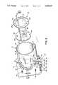
- FIG. 1illustrates a cutaway perspective view of a rinser dryer process system, the present invention
- FIG. 2illustrates an exploded view of a removable bowl and a mounting plate
- FIG. 3illustrates a side view in cross section of the rinser dryer
- FIG. 4illustrates a front view of the rinser dryer with the front panel, drive plate and a portion of the seal housing removed;
- FIG. 5illustrates a back view of the rinser dryer
- FIG. 6illustrates a perspective view of the exhaust gas manifold and integral removable broken chip collector assembly
- FIGS. 7A and 7Billustrate a composite cross section taken along line 7A--7A and 7B--7B of FIG. 4 also including a drive plate and seal housing;
- FIG. 8illustrates a pneumatic and fluid flow chart for the rinser dryer
- FIG. 9illustrates a block diagram flow chart for the rinser dryer process system
- FIG. 10illustrates a perspective view of a removable bowl liner in a bowl.
- FIG. 1illustrates a rinser dryer system 10, the present invention, including a quick and readily removable and interchangeable rinse bowl 12 positioned on a mounting plate 14.
- Removable bowl 12defines a processing chamber within which semiconductor wafer, substrates, disks and similar units are processed.
- Quick action internally threaded release knobs 16-22as also illustrated in FIGS. 2 and 4, secure the removable bowl 12 to the mounting plate 14 as described later in detail.
- the bowl 12can be stainless steel, TEFLON, or other suitable material.
- the bowlcan be of one material and have a removable liner for further quick change-over.
- a plurality of blanket heaters 13a-13nare positioned about the bowl for internal temperature control.
- the direct drive motor 24secures to the mounting plate 14 to rotate a cassette rotor 26 within the confines of the removable bowl 12.
- Pressurized deionized H 2 O or a like liquidenters the removable bowl 12 through a DI H 2 O spray manifold 28 for pressure rinsing of process chemical from the wafers 32 contained in a wafer cassette 34 as the rotor 26, wafers 32 and cassette 34 spin past the rinse manifold 28 in the rinser dryer 10.
- Nitrogen or a like gasenters the removable bowl 12 through manifold 30 for process drying after rising is completed as either predetermined or as detected by a resistivity sensor.
- the mounting plate 14, the removable bowl 12 and associated component membersare positioned within a rectangular configured framework 36.
- the configured framework 36positions over and about a base member 38 including a bottom 40, vertical sides 42 and 44 and vertical sides 46 and 48 as illustrated in FIG. 3, and a flange lip 50 which extends horizontally and outwardly over the vertical sides 42-48 to accommodate mounting of the base member 38 on a platform top and within a like configured cavity.
- Plastic side panel 52, a back panel 56 and a top panel 58, as illustrated in FIG. 3,position over and about the configured framework 36.
- An electronic control module 60slides into a water proof enclosure 62 positioned over the top panel 58, which is illustrated in FIG. 3.
- the enclosure 62 bottomincludes the upper portion of panel 58 as its bottom part, side member 64, and side member 66 as illustrated in FIGS.
- FIGS. 3 and 4a top member 68 and a portion of the back panel 56.
- Side panel referencesare also illustrated in FIGS. 3 and 4.
- An angled front panel 70fits over the angled portion of the configured framework 36 and includes quick release front panel release screws 72-78, a front access opening which is covered by a see-through sealed door 80, door hinge 81, door handle 82, start button 84, stop button 86, and a circular inflatable door seal 87 as illustrated in FIG. 3.
- FIG. 2illustrates an exploded view of the removable bowl 12 and mounting plate 14 assembly where all numerals correspond to those elements previously described.
- a rotary drive plate 88, driven by motor 24 as illustrated in FIG. 1, and a bowl seal 89 positioned centrally on the mounting plate 14,are illustrated and described in detail in FIGS. 3 and 7.
- Securing means in the shouldered form of studs 90 and 94 and ordinary studs 92 and 96, as also illustrated in FIG. 4,are positioned to assure proper indexing and orientation of the removable bowl 12 when the corresponding geometrically configured polarized bowl brackets 98-104 mounted on the removable bowl 12 fit properly over, and only over, the shouldered studs 90-96.
- Bowl brackets 98-104 or like structureare positioned about the removable bowl 12, as illustrated, for engagement over and about corresponding studs 90-96, respectively.
- the bowl 12, including cylindrical side portion 12b, circular back plate 12a and back plate hole 12c, drain augmenting trough 97 and the mounting plate 14,are positioned in appropriate angular relationship to facilitate the flow of rinse fluid from the bowl 12, as is described later in detail.
- a nitrogen supply port 101, a DI H 2 O supply port 103 and an additional DI H 2 O supply port 105are positioned on the front lower portion of the mounting plate to allow important and easy frontal access capabilities for ease of rapid coupling or decoupling of supply N 2 or DI H 2 O.
- a drain meanswhich includes a gas/liquid separating manifold 106, as described later in detail, is mounted with appropriate hardware to the back side of the mounting plate 14, as illustrated in FIGS. 3, 4, 5, and 6.
- a removable broken chip or particle collector or separator 108is positioned within a lower portion, and is integral to the exhaust gas manifold 106. The collector 108 is extracted manually to remove broken particles and bits of fractured or broken chips. This collector 108 is later described in detail in FIGS. 3, 4, and 6.
- the collector base plate 110is secured to the exhaust gas manifold 106 with knurled/slotted machine screws 112 and 114.
- a resistivity sensor, pH sensor, or like qualitative sensor 116is positioned in hole 118 for sensing acidity or pH of rinse effluent as sensed in the removable broken particle collector 108 prior to its discharge and drainage from the liquid drainage port 120.
- the rotor 26fits over, against, and about the drive plate 88 and is secured thereto by a hand-tightened knurled rotor mounting nut 121.
- the rotor 26includes rotor plate 122, a plurality of fixture securement holes 124a-124n, and a rotor centering hole 125.
- a second rotor plate 126includes fixture securement holes 128a-128n, cassette alignment hole 130 and parallel support members 132-136 affixed between rotor plates 122 and 126.
- FIG. 3illustrates a side view of the rinser dryer system 10 in cross section which also illustrates one mode of operation where all numerals correspond to those elements previously described.
- Rotor motor 24 and a motor mounting plate 138are affixed to mounting plate 14 by vibration dampening rubber motor suspension members 140-146 and appropriate mounting hardware.
- a seal housing 148affixes to motor 24, motor mount plate 138 and extends through the mounting plate 14.
- a drive plate 88is driven by the motor 24, and includes an annular ring 150 mated with corresponding annular groove 152 in the seal housing 148 to form a labyrinth or second seal 154 between the stationary seal housing 148 and the rotary motion drive plate 88.
- a bowl or first seal 89is positioned between the mounting plate 14 and the back wall 12a of the removable bowl 12 to seal the interior of the removable bowl 12 from ambient atmosphere.
- a door seal 87is pressured with N 2 between the see-through door 79 and the panel front 70 to effect a door seal.
- Manifolds 28 and 30are secured to the mounting plate 14 with sealing rings 29 and 31 therebetween.
- Deionized wateris injected through port 28a and into manifold 28 to rinse the wafer and silicon or gallium arsenide wafers, substrates, masks or disks as both spin about an axis as driven by the motor.
- N 2is injected into port 30a and into manifold 30 to complete the drying process. Rinse liquids and gases gather in the bowl trough 97 and exit with the help of gravity via the bowl exhaust tube 160 and into the exhaust gas manifold 106.
- the entire motor-removable drum rotor assemblyis mounted at an angle of ten degrees by way of example and for purposes of illustration only, and not to be construed as limiting of the present invention, thus assisting in gravitational augmentation of effluent removal from the interior of the removable bowl 12.
- the angle of mountingcan be configured to be between a horizontal plane and a vertical plane, but preferably in a range of 5° to 35° or 5° to 85°.
- Pressurized N 2 from manifold 30also forces internal gases through the bowl exhaust tube 160 and into the main chamber 162 of the exhaust manifold 106.
- Both fan-shaped and atomizing spray manifolds of 8 nozzleseach are located about the wafers. Therefore, gravity and gas flow assist in a downward, continuous flow of chemicals.
- On-axis horizontal rotation spray applicationproduces uniform coverage on both sides of the product.
- the exhaust manifold 106includes a main chamber 162, an inlet port 164, removable broken silicon wafer collector 108, a collector chamber 166, a gate valve 168, a pneumatic gate valve actuator 170, an angled gas exhaust duct 172, and is connected to an external vacuum tube 74 to exhaust gaseous fumes from the rinser dryer 10.
- the exhaust manifold 106 and associated componentsare described later in detail in FIGS. 4 and 6. Liquids exit the bowl exhaust tube 160 and into the main chamber 162, through a perforated plate 176 on the broken particle collector 108, into the collector chamber 166, past a resistivity sensor 116, out of the collector chamber 166, over a vertical dam member 167 as illustrated in FIG. 4, into a lower side portion of the main chamber, and then overboard through a forward facing drain fitting 177 as illustrated in FIGS. 4 and 6 to be recycled or dumped as the need requires.
- the bowl 12including large portions of the broken pieces, can be readily removed by easily removing the front panel 70, removing the rotor mount nut 120, the rotor 26, and releasing the quick action release knobs 16-22 for easy removal of the bowl 12 and the broken pieces for facilitation of cleaning external to the rinser dryer 10.
- Any smaller broken partsare deposited on the perforated plate 176 of the broken wafer collector 108. If the particles are smaller than the perforations 178a-178n in the perforated plate 176, then the particles pass through the perforations to be contained in the interior of the collector chamber 166 by the dam member 167. The broken wafer 108 can then be removed with the chips or fragments deposited on the perforated plate 176 or within the collector chamber 166 for external cleaning of the wafer collector 108 prior to its next use.
- a positioner brake 180which acts against the circular stop plate 182 to quickly stop rotation of the motor 24 and rotor 26 to position and orient the rotor 26 in a position to accept a wafer basket, is controlled by the electronic control module 60.
- the electronic control modulealso controls various functions such as, but not limited to, pneumatic solenoids on pneumatic solenoid manifold 184 mounted on bracket 186, gate valve actuator 170, N 2 supply, DI H 2 O supply, start sequence, stop sequence and numerous other functions as described later in detail in FIG. 8.
- FIG. 4illustrates a front view of the rinser dryer system 10 with the front panel 70 removed where all numerals correspond to those elements previously described.
- the removable bowl 12, the mounting plate 14 and the associated componentsare viewed with respect to line 4-4 of FIG. 3.
- the bowl seal 89, a portion of the seal housing, and the drive plate 88are also removed exposing the inner portions of seal housing 148 and the nitrogen inlet and outlet labyrinth ports 156a and 158a, respectively.
- Air ports 190a, 190b and 190cposition in the seal housing 148 for the exhausting of gases internal to the seal housing into the cabinetry interior where it is exited through the exhaust gas manifold system.
- a collector base plate 110is illustrated as being secured to and against the exhaust gas manifold 106. Illustrated in particular is the dam member 167 and side bottom members forming one end of collector chamber 166.
- a chamber end member 196is illustrated in FIG. 3.
- FIG. 5illustrates a back view of the rinser dryer system 10 where all numerals correspond to those elements previously described.
- a pressure switch 222, adjustable restrictor 224, and a filter 226mount as illustrated in the figure.
- FIG. 6illustrates a perspective view of the exhaust gas manifold 106 and the integral removable chip or particle collector 108, where all numerals correspond to those elements previously described.
- the collector 108includes a base plate 110, knurled easily removable slotted screws 112 and 114, a threaded sensor receptor hole 118, resistivity sensor, pH sensor, or like qualitative sensor 116, a perforated top plate 176, perforations 178a-178n through top plate 176, a dammed collector chamber 166 formed by the perforated top plate 176, a dam vertical wall member 167, an end wall 196, bottom wall 198 as illustrated in FIG. 3, and side wall member 192 as illustrated in FIG. 4.
- any small broken chips or particlescan settle on the perforated plate 176 or migrate through the perforations 178a-178n and are trapped within the chamber 166, whereupon the wafer collector 108 is removed for external cleansing.
- the wafer collectoris positioned within the manifold chamber 162 of the exhaust gas manifold 106, and functions to collect broken chips or particles, and to also sense resistivity, pH or other qualitative factor of the wash or rinse fluid.
- the exhaust gas manifold 106includes a mounting plate 228, including a planar manifold inlet surface member 230 and a planar collector mounting surface member 232.
- the planar mounting memberincludes screw holes 234 and 236 for mating with knurled/slotted screws 112 and 114 in the base plate 110.
- a sealing gasket 238is positioned around and about a rectangular wafer collector entry hole 240 to effect and provide a seal between the base plate 110, the planar collector member 232, and the rectangular wafer collector hole 240.
- the planar manifold inlet member 230includes a manifold inlet port 162 and holes 242-248 for securement to the back side of the mounting plate 14.
- a planar top member 250 and opposing side members 252 and 254, a bottom member 194, and an obliquely mounted manifold member 258are positioned beneath the pneumatic actuating cylinder and between opposing configured side members 252 and 254.
- a vertical back member 259completes the exhaust gas manifold 106.
- a rectangular gate valve chamber 260positioned over and about the corresponding edges of top member 250, parallel opposing side members 252 and 254, an oblique member 258, includes a sliding gate valve member 168 and gate valve tab 168a which are actuated by pneumatic valve actuator 170 and actuator arm 262 to exhaust gaseous particles and vapors through the attached exhaust gas outlet port 172 to the outboard tube 174.
- the pneumatic actuating cylinder 170is secured to the exhaust gas manifold oblique member 258 by means of brackets 264 and 266 as illustrated in FIG. 5.
- a forward facing liquid drainis positioned in the side member 252 to drain effluent from the main chamber 162 after its passage through the collector chamber 166.
- FIGS. 7A and 7Billustrate a composite cross section taken along line 7A--7A and 7B--7B of FIG. 4 where cross section 7A--7A is illustrated in a normal configuration and cross section 7B--7B is rotated 90° counter clockwise about the centerline to show a continuous figure. All numerals correspond to those elements previously described.
- the drive plate 88 and only a portion of the seal housing 148are not illustrated in FIG. 4, the members are included in this cross section for purposes of completeness and clarity.
- Seal housing 148is positioned in a hole 268 in mounting plate 14, and accommodates the drive motor 24 centrally in a drive motor hole 270.
- the seal housingis positioned over and about a motor mount plate 138.
- Appropriate hardwaresecures the motor mount plate 138 via rubber suspension members 140-146 to the mounting plate 14 as illustrated in FIG. 3.
- a press fitting 272is positioned over the motor drive shaft 274, and also accommodates cylindrical shaft portion 276 of drive plate 88, thus securing the drive plate to the motor 24.
- a seal housing clamp plate 148a containing annular groove 152is secured with appropriate hardware to hold bowl seal member 148 and sealing the gasket seal 89 against circular bowl back 12a and mounting plate 14 to seal the interior of the removable bowl 12 from the atmosphere.
- the annular ring in the drive plate 88mates with the annular groove 152 of the seal housing clamp plate 148a to form a labyrinth seal 154 which is sealed and pressurized by N 2 entering the N 2 inlet fitting 156, N 2 inlet fitting 158 as illustrated in FIG. 4, passing through the N 2 inlet port 156a and N 2 inlet port 158 as illustrated in FIG. 4, through the labyrinth seal 154, through the N 2 outlet ports 158a, 190a-190b as illustrated in FIG. 4, and also through the N 2 drain outlet fitting 188.
- the curtain of gasthus provided at the seal creates a differential pressure, friction free, particle barrier at the motor shaft and about a press fit baffle 278 positioned concentric to motor shaft 274.
- the rotor plate hole 125centers over and aligns with the cylindrical shaft 286 prior to the placement and tightening of the knurled mounting knob 120 over the rotor plate 122.
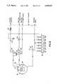
- FIG. 8illustrates a pneumatic and fluid flow chart of the rinser dryer system 10 where all numerals correspond to those elements previously described.
- the electronic control module 60senses and controls pneumatic solenoids 198-208 in the solenoid manifold 184 which in turn actuates valves 210-218 and other pneumatic devices including a motor stop actuator and a door seal.
- the systemis controlled by a microprocessor.
- a drying valve 210is operated by a 4-way dryer valve solenoid activator 198.
- a rinse valve 212is operated by a 4-way rinse solenoid actuator 200.
- An N 2 low flow bowl purge valve 214is operated by a 4-way bowl purge solenoid activator 202.
- a rinse manifold purge valve 216is operated by a 4-way rinse manifold purge solenoid activator 204.
- a normally closed rinse valve 212opens, the recirculating valve 218 is closed by a pneumatic connection to prevent system back flow.
- the 4-way solenoid activator 206ports pneumatic pressure to the motor rotor stop positioner to stop motor rotation.
- a 3-way door seal solenoid activator 208pressurizes the door seal 87 during rinse/dry processing.
- a filter 226 and pressure switch 222are in series with the N 2 supply line.
- An adjustable restrictoris in series with the deionized water reclaim load to control return flow. All connecting tubing is TEFLON PFA, a fluoropolymer, or like material as required.
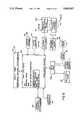
- FIG. 9illustrates a block diagram flow chart for the rinser dryer system 10 where all numerals correspond to those elements previously described.
- a main logic microprocessor board 300interacts with the display panel 302 of the electronic control module 60 to display useful user information such as, but not limited to, programming information, switch position and status displays.
- the main logic board 300receives inputs from the resistivity sensor 116, operator switches 84 and 86, status sensors 304 and relay board 306.
- the main logic board 300interacts with external connectors status sensors 308 and relay board 306.
- the relay board 306controls an antistatic device 310, process bowl heaters 13, motor control 312, and the motor brake 182.
- Input/output circuitry in the main logic board 300also controls solenoid valves 198-208, pneumatic process control valves 210-218 and H 2 O and N 2 inputs into the process bowl 12.
- a control for an optional pneumatic door actuator for raising or lowering a sliding dooris also provided by pneumatic door control valves 314.
- FIG. 10illustrates a perspective view of a removable bowl liner 350 in a bowl 12.
- the removable bowl linercan be of TEFLON, a fluoropolymer, or other material.
- the bowl 12 and bowl liner 350can be incorporated into a single bowl member where the bowl is entirely of one material.
- a heater and air filtercan be connected to the N 2 line through a pneumatic valve for introducing heated filter air or gas to the bowl.
- the doorcan be a hinged door or a sliding door to conserve horizontal space.
Landscapes
- Engineering & Computer Science (AREA)
- Physics & Mathematics (AREA)
- Condensed Matter Physics & Semiconductors (AREA)
- General Physics & Mathematics (AREA)
- Manufacturing & Machinery (AREA)
- Computer Hardware Design (AREA)
- Microelectronics & Electronic Packaging (AREA)
- Power Engineering (AREA)
- Cleaning Or Drying Semiconductors (AREA)
Abstract
Description
Claims (25)
Priority Applications (1)
| Application Number | Priority Date | Filing Date | Title |
|---|---|---|---|
| US07/653,886US5095927A (en) | 1987-04-27 | 1991-02-08 | Semiconductor processor gas-liquid separation |
Applications Claiming Priority (2)
| Application Number | Priority Date | Filing Date | Title |
|---|---|---|---|
| US07/042,951US5022419A (en) | 1987-04-27 | 1987-04-27 | Rinser dryer system |
| US07/653,886US5095927A (en) | 1987-04-27 | 1991-02-08 | Semiconductor processor gas-liquid separation |
Related Parent Applications (1)
| Application Number | Title | Priority Date | Filing Date |
|---|---|---|---|
| US07/042,951DivisionUS5022419A (en) | 1987-04-27 | 1987-04-27 | Rinser dryer system |
Publications (1)
| Publication Number | Publication Date |
|---|---|
| US5095927Atrue US5095927A (en) | 1992-03-17 |
Family
ID=26719838
Family Applications (1)
| Application Number | Title | Priority Date | Filing Date |
|---|---|---|---|
| US07/653,886Expired - LifetimeUS5095927A (en) | 1987-04-27 | 1991-02-08 | Semiconductor processor gas-liquid separation |
Country Status (1)
| Country | Link |
|---|---|
| US (1) | US5095927A (en) |
Cited By (20)
| Publication number | Priority date | Publication date | Assignee | Title |
|---|---|---|---|---|
| US5608943A (en)* | 1993-08-23 | 1997-03-11 | Tokyo Electron Limited | Apparatus for removing process liquid |
| US6105592A (en)* | 1997-07-21 | 2000-08-22 | Semitool, Inc. | Gas intake assembly for a wafer processing system |
| US6125863A (en)* | 1998-06-30 | 2000-10-03 | Semitool, Inc. | Offset rotor flat media processor |
| US6239038B1 (en) | 1995-10-13 | 2001-05-29 | Ziying Wen | Method for chemical processing semiconductor wafers |
| US6286524B1 (en)* | 1998-02-27 | 2001-09-11 | Kabushiki Kaisha Toshiba | Wafer drying apparatus and method with residual particle removability enhancement |
| US20020000240A1 (en)* | 2000-06-30 | 2002-01-03 | Yuji Kamikawa | Liquid processing apparatus |
| US6350322B1 (en) | 1997-03-21 | 2002-02-26 | Micron Technology, Inc. | Method of reducing water spotting and oxide growth on a semiconductor structure |
| US6391110B1 (en)* | 1996-09-24 | 2002-05-21 | Tokyo Electron Limited | Method and apparatus for cleaning treatment |
| US6398879B1 (en) | 1996-09-24 | 2002-06-04 | Tokyo Electron Limited | Method and apparatus for cleaning treatment |
| US6423152B1 (en)* | 1998-06-29 | 2002-07-23 | Intel Sampling As | Method and apparatus for treatment of internal surfaces in a closed-loop fluid system |
| US6536452B1 (en) | 1999-04-27 | 2003-03-25 | Tokyo Electron Limited | Processing apparatus and processing method |
| US6622398B2 (en) | 1999-08-26 | 2003-09-23 | Semitool, Inc. | Method of ozone conversion in semiconductor manufacturing |
| US6691720B2 (en)* | 2001-07-16 | 2004-02-17 | Semitool, Inc. | Multi-process system with pivoting process chamber |
| US20040040587A1 (en)* | 2002-09-03 | 2004-03-04 | Moon-Taek Lim | Substrate detecting apparatus |
| USRE39241E1 (en)* | 1998-03-27 | 2006-08-22 | Entegris, Inc. | Modular SMIF pod breather, adsorbent, and purge cartridges |
| US20080175999A1 (en)* | 2007-01-22 | 2008-07-24 | Tokyo Electron Limited | Heating apparatus, heating method, and computer readable storage medium |
| US20100112191A1 (en)* | 2008-10-30 | 2010-05-06 | Micron Technology, Inc. | Systems and associated methods for depositing materials |
| US20120027543A1 (en)* | 2009-04-24 | 2012-02-02 | Michael Reising | Method and device for introducing and removing substrates |
| US20210040674A1 (en)* | 2018-02-01 | 2021-02-11 | Qingdao Haier Drum Washing Machine Co., Ltd. | Air duct conversion device and clothing treating device |
| US20230381827A1 (en)* | 2022-05-25 | 2023-11-30 | Raytheon Technologies Corporation | One piece high temperature washer |
Citations (23)
| Publication number | Priority date | Publication date | Assignee | Title |
|---|---|---|---|---|
| US1793798A (en)* | 1928-07-05 | 1931-02-24 | Sarah B Harker | Dishwashing machine |
| US2573128A (en)* | 1947-04-05 | 1951-10-30 | Cavicchioli Mario | Device in dishwashing machine for recovering silverware and the like |
| US2675012A (en)* | 1952-10-18 | 1954-04-13 | Frank J Scales | Washing apparatus for automotive and machine parts and assmeblies |
| US3079286A (en)* | 1962-03-02 | 1963-02-26 | Detrex Chem Ind | Enclosed cold solvent spray cleaner |
| US3116744A (en)* | 1962-10-26 | 1964-01-07 | Earl E Hager | Washing machine for small articles |
| US3203434A (en)* | 1963-12-06 | 1965-08-31 | Western Electric Co | Chemical polishing machine |
| US3585128A (en)* | 1969-07-28 | 1971-06-15 | Gen Electric | Pre-wash scrap basket for dishwasher |
| US3585668A (en)* | 1969-06-02 | 1971-06-22 | Bell Telephone Labor Inc | Brush cleaning apparatus for semiconductor slices |
| US3643671A (en)* | 1967-12-14 | 1972-02-22 | Bosch Gmbh Robert | Apparatus for treating elements of circular outline |
| US3664872A (en)* | 1970-09-18 | 1972-05-23 | Western Electric Co | Method for scrubbing thin, fragile slices of material |
| US3748677A (en)* | 1970-09-18 | 1973-07-31 | Western Electric Co | Methods and apparatus for scrubbing thin, fragile slices of material |
| US3939514A (en)* | 1974-11-11 | 1976-02-24 | Kayex Corporation | Apparatus for cleaning thin, fragile wafers of a material |
| US3970471A (en)* | 1975-04-23 | 1976-07-20 | Western Electric Co., Inc. | Methods and apparatus for treating wafer-like articles |
| US4092176A (en)* | 1975-12-11 | 1978-05-30 | Nippon Electric Co., Ltd. | Apparatus for washing semiconductor wafers |
| US4132567A (en)* | 1977-10-13 | 1979-01-02 | Fsi Corporation | Apparatus for and method of cleaning and removing static charges from substrates |
| US4208760A (en)* | 1977-12-19 | 1980-06-24 | Huestis Machine Corp. | Apparatus and method for cleaning wafers |
| US4226642A (en)* | 1979-02-06 | 1980-10-07 | American Sterilizer Company | System providing for decontamination washing and/or biocidal treatment |
| US4286541A (en)* | 1979-07-26 | 1981-09-01 | Fsi Corporation | Applying photoresist onto silicon wafers |
| US4300581A (en)* | 1980-03-06 | 1981-11-17 | Thompson Raymon F | Centrifugal wafer processor |
| US4440185A (en)* | 1982-08-18 | 1984-04-03 | Wiltse Dean P | Support stand for a food slicer |
| US4456022A (en)* | 1981-10-16 | 1984-06-26 | Roberts Donald E | Flatware washing machine |
| US4523764A (en)* | 1982-06-25 | 1985-06-18 | M.A.N. Maschinenfabrik Augsburg-Nurnberg Aktiengesellschaft | Fluid-sealed shaft seal with bores for supplying and discharging fluid |
| US4694527A (en)* | 1983-07-06 | 1987-09-22 | Fujitsu Limited | Mask washing apparatus for production of integrated circuit |
- 1991
- 1991-02-08USUS07/653,886patent/US5095927A/ennot_activeExpired - Lifetime
Patent Citations (23)
| Publication number | Priority date | Publication date | Assignee | Title |
|---|---|---|---|---|
| US1793798A (en)* | 1928-07-05 | 1931-02-24 | Sarah B Harker | Dishwashing machine |
| US2573128A (en)* | 1947-04-05 | 1951-10-30 | Cavicchioli Mario | Device in dishwashing machine for recovering silverware and the like |
| US2675012A (en)* | 1952-10-18 | 1954-04-13 | Frank J Scales | Washing apparatus for automotive and machine parts and assmeblies |
| US3079286A (en)* | 1962-03-02 | 1963-02-26 | Detrex Chem Ind | Enclosed cold solvent spray cleaner |
| US3116744A (en)* | 1962-10-26 | 1964-01-07 | Earl E Hager | Washing machine for small articles |
| US3203434A (en)* | 1963-12-06 | 1965-08-31 | Western Electric Co | Chemical polishing machine |
| US3643671A (en)* | 1967-12-14 | 1972-02-22 | Bosch Gmbh Robert | Apparatus for treating elements of circular outline |
| US3585668A (en)* | 1969-06-02 | 1971-06-22 | Bell Telephone Labor Inc | Brush cleaning apparatus for semiconductor slices |
| US3585128A (en)* | 1969-07-28 | 1971-06-15 | Gen Electric | Pre-wash scrap basket for dishwasher |
| US3748677A (en)* | 1970-09-18 | 1973-07-31 | Western Electric Co | Methods and apparatus for scrubbing thin, fragile slices of material |
| US3664872A (en)* | 1970-09-18 | 1972-05-23 | Western Electric Co | Method for scrubbing thin, fragile slices of material |
| US3939514A (en)* | 1974-11-11 | 1976-02-24 | Kayex Corporation | Apparatus for cleaning thin, fragile wafers of a material |
| US3970471A (en)* | 1975-04-23 | 1976-07-20 | Western Electric Co., Inc. | Methods and apparatus for treating wafer-like articles |
| US4092176A (en)* | 1975-12-11 | 1978-05-30 | Nippon Electric Co., Ltd. | Apparatus for washing semiconductor wafers |
| US4132567A (en)* | 1977-10-13 | 1979-01-02 | Fsi Corporation | Apparatus for and method of cleaning and removing static charges from substrates |
| US4208760A (en)* | 1977-12-19 | 1980-06-24 | Huestis Machine Corp. | Apparatus and method for cleaning wafers |
| US4226642A (en)* | 1979-02-06 | 1980-10-07 | American Sterilizer Company | System providing for decontamination washing and/or biocidal treatment |
| US4286541A (en)* | 1979-07-26 | 1981-09-01 | Fsi Corporation | Applying photoresist onto silicon wafers |
| US4300581A (en)* | 1980-03-06 | 1981-11-17 | Thompson Raymon F | Centrifugal wafer processor |
| US4456022A (en)* | 1981-10-16 | 1984-06-26 | Roberts Donald E | Flatware washing machine |
| US4523764A (en)* | 1982-06-25 | 1985-06-18 | M.A.N. Maschinenfabrik Augsburg-Nurnberg Aktiengesellschaft | Fluid-sealed shaft seal with bores for supplying and discharging fluid |
| US4440185A (en)* | 1982-08-18 | 1984-04-03 | Wiltse Dean P | Support stand for a food slicer |
| US4694527A (en)* | 1983-07-06 | 1987-09-22 | Fujitsu Limited | Mask washing apparatus for production of integrated circuit |
Cited By (47)
| Publication number | Priority date | Publication date | Assignee | Title |
|---|---|---|---|---|
| US5608943A (en)* | 1993-08-23 | 1997-03-11 | Tokyo Electron Limited | Apparatus for removing process liquid |
| US6239038B1 (en) | 1995-10-13 | 2001-05-29 | Ziying Wen | Method for chemical processing semiconductor wafers |
| US6391110B1 (en)* | 1996-09-24 | 2002-05-21 | Tokyo Electron Limited | Method and apparatus for cleaning treatment |
| US6398879B1 (en) | 1996-09-24 | 2002-06-04 | Tokyo Electron Limited | Method and apparatus for cleaning treatment |
| US7204889B2 (en) | 1997-03-21 | 2007-04-17 | Micron Technology, Inc. | Method of reducing water spotting and oxide growth on a semiconductor structure |
| US20040020521A1 (en)* | 1997-03-21 | 2004-02-05 | Yates Donald L. | Method of reducing water spotting and oxide growth on a semiconductor structure |
| US6350322B1 (en) | 1997-03-21 | 2002-02-26 | Micron Technology, Inc. | Method of reducing water spotting and oxide growth on a semiconductor structure |
| US20020050483A1 (en)* | 1997-03-21 | 2002-05-02 | Yates Donald L. | Method of reducing water spotting and oxide growth on a semiconductor structure |
| US20040139991A1 (en)* | 1997-03-21 | 2004-07-22 | Yates Donald L. | Method of reducing water spotting and oxide growth on a semiconductor structure |
| US20050252534A1 (en)* | 1997-03-21 | 2005-11-17 | Yates Donald L | Method of reducing water spotting and oxide growth on a semiconductor structure |
| US20060011215A1 (en)* | 1997-03-21 | 2006-01-19 | Yates Donald L | Method and reducing water spotting and oxide growth on a semiconductor structure |
| US7422639B2 (en) | 1997-03-21 | 2008-09-09 | Micron Technology, Inc. | Method of reducing water spotting and oxide growth on a semiconductor structure |
| US6896740B2 (en) | 1997-03-21 | 2005-05-24 | Micron Technology, Inc. | Method of reducing water spotting and oxide growth on a semiconductor structure |
| US6601595B2 (en) | 1997-03-21 | 2003-08-05 | Micron Technology, Inc. | Method of reducing water spotting and oxide growth on a semiconductor structure |
| US6607001B1 (en)* | 1997-03-21 | 2003-08-19 | Micron Technology, Inc. | System of reducing water spotting and oxide growth on a semiconductor structure |
| US7163019B2 (en) | 1997-03-21 | 2007-01-16 | Micron Technology, Inc. | Method of reducing water spotting and oxide growth on a semiconductor structure |
| US20030192574A1 (en)* | 1997-03-21 | 2003-10-16 | Yates Donald L. | Method of reducing water spotting and oxide growth on a semiconductor structure |
| US6641677B1 (en) | 1997-03-21 | 2003-11-04 | Micron Technology, Inc. | Method of reducing water spotting and oxide growth on a semiconductor structure |
| US6645311B2 (en) | 1997-03-21 | 2003-11-11 | Micron Technology, Inc. | Method of reducing water spotting and oxide growth on a semiconductor structure |
| US6656289B2 (en) | 1997-03-21 | 2003-12-02 | Micron Technology, Inc. | Method of reducing water spotting and oxide growth on a semiconductor structure |
| US6105592A (en)* | 1997-07-21 | 2000-08-22 | Semitool, Inc. | Gas intake assembly for a wafer processing system |
| US6286524B1 (en)* | 1998-02-27 | 2001-09-11 | Kabushiki Kaisha Toshiba | Wafer drying apparatus and method with residual particle removability enhancement |
| USRE39241E1 (en)* | 1998-03-27 | 2006-08-22 | Entegris, Inc. | Modular SMIF pod breather, adsorbent, and purge cartridges |
| US6423152B1 (en)* | 1998-06-29 | 2002-07-23 | Intel Sampling As | Method and apparatus for treatment of internal surfaces in a closed-loop fluid system |
| US6125863A (en)* | 1998-06-30 | 2000-10-03 | Semitool, Inc. | Offset rotor flat media processor |
| US6536452B1 (en) | 1999-04-27 | 2003-03-25 | Tokyo Electron Limited | Processing apparatus and processing method |
| US20030127117A1 (en)* | 1999-04-27 | 2003-07-10 | Kyouji Kohama | Processing apparatus and processing method |
| DE10020523B4 (en)* | 1999-04-27 | 2007-06-21 | Tokyo Electron Ltd. | Device and method for processing an object |
| US6895979B2 (en) | 1999-04-27 | 2005-05-24 | Tokyo Electron Limited | Processing apparatus and processing method |
| US6622398B2 (en) | 1999-08-26 | 2003-09-23 | Semitool, Inc. | Method of ozone conversion in semiconductor manufacturing |
| US20050103364A1 (en)* | 2000-06-30 | 2005-05-19 | Yuji Kamikawa | Liquid processing apparatus |
| US20020000240A1 (en)* | 2000-06-30 | 2002-01-03 | Yuji Kamikawa | Liquid processing apparatus |
| US7284560B2 (en)* | 2000-06-30 | 2007-10-23 | Toktyo Electron Limited | Liquid processing apparatus |
| US6691720B2 (en)* | 2001-07-16 | 2004-02-17 | Semitool, Inc. | Multi-process system with pivoting process chamber |
| US20040040573A1 (en)* | 2001-07-16 | 2004-03-04 | Semitool, Inc. | Multi-process system |
| US7005010B2 (en) | 2001-07-16 | 2006-02-28 | Semitool, Inc. | Multi-process system |
| US20040040587A1 (en)* | 2002-09-03 | 2004-03-04 | Moon-Taek Lim | Substrate detecting apparatus |
| US7219676B2 (en)* | 2002-09-03 | 2007-05-22 | Samsung Electronics Co., Ltd. | Substrate detecting apparatus |
| US7992318B2 (en)* | 2007-01-22 | 2011-08-09 | Tokyo Electron Limited | Heating apparatus, heating method, and computer readable storage medium |
| US20080175999A1 (en)* | 2007-01-22 | 2008-07-24 | Tokyo Electron Limited | Heating apparatus, heating method, and computer readable storage medium |
| US8186077B2 (en) | 2007-01-22 | 2012-05-29 | Tokyo Electron Limited | Heating apparatus, heating method, and computer readable storage medium |
| US20100112191A1 (en)* | 2008-10-30 | 2010-05-06 | Micron Technology, Inc. | Systems and associated methods for depositing materials |
| US20120027543A1 (en)* | 2009-04-24 | 2012-02-02 | Michael Reising | Method and device for introducing and removing substrates |
| US8740536B2 (en)* | 2009-04-24 | 2014-06-03 | Singulus Technologies Ag | Method and device for introducing and removing substrates |
| US20210040674A1 (en)* | 2018-02-01 | 2021-02-11 | Qingdao Haier Drum Washing Machine Co., Ltd. | Air duct conversion device and clothing treating device |
| US12071720B2 (en)* | 2018-02-01 | 2024-08-27 | Qingdao Haier Laundry Electric Appliances Co., Ltd. | Air duct conversion device and clothing treating device |
| US20230381827A1 (en)* | 2022-05-25 | 2023-11-30 | Raytheon Technologies Corporation | One piece high temperature washer |
Similar Documents
| Publication | Publication Date | Title |
|---|---|---|
| US5154199A (en) | Semiconductor processor draining | |
| US5221360A (en) | Semiconductor processor methods | |
| US5095927A (en) | Semiconductor processor gas-liquid separation | |
| US4300581A (en) | Centrifugal wafer processor | |
| JP3476395B2 (en) | Clean room and clean room air conditioning method | |
| US6432214B2 (en) | Cleaning apparatus | |
| US5562113A (en) | Centrifugal wafer carrier cleaning apparatus | |
| US7216655B2 (en) | Wafer container washing apparatus | |
| US20020046760A1 (en) | Wafer container washing apparatus | |
| US5000208A (en) | Wafer rinser/dryer | |
| JP2005109523A (en) | Pod cleaning and drying equipment for semiconductor wafer and the like | |
| KR970011644B1 (en) | A coating apparatus | |
| JP3088311B2 (en) | Packing tower type dust collector | |
| JP2002334863A (en) | Method and apparatus for cleaning and drying door shell for foup | |
| JP3171965B2 (en) | Spin cleaning and drying equipment | |
| JP3961749B2 (en) | Substrate cleaning apparatus, substrate processing apparatus, and substrate processing method | |
| US6105592A (en) | Gas intake assembly for a wafer processing system | |
| US20040010930A1 (en) | Cross flow processor | |
| JPH06333899A (en) | Chemical treatment method and treatment device therefor | |
| CN116759373A (en) | Wafer post-processing device | |
| JPH1041270A (en) | Wafer treating apparatus | |
| JP3401428B2 (en) | Processing equipment | |
| JP2002043272A (en) | Substrate cleaning apparatus and substrate processing apparatus | |
| JPH07201798A (en) | Single-wafer substrate processing method and apparatus | |
| JPS6294930A (en) | developing device |
Legal Events
| Date | Code | Title | Description |
|---|---|---|---|
| AS | Assignment | Owner name:SEMITOOL, INC., A CORP. OF MONTANA, MONTANA Free format text:ASSIGNMENT OF ASSIGNORS INTEREST.;ASSIGNORS:THOMPSON, RAYMON F.;OWCZARZ, ALEKSANDER;REEL/FRAME:005606/0606 Effective date:19910130 | |
| STCF | Information on status: patent grant | Free format text:PATENTED CASE | |
| FEPP | Fee payment procedure | Free format text:PAT HLDR NO LONGER CLAIMS SMALL ENT STAT AS INDIV INVENTOR (ORIGINAL EVENT CODE: LSM1); ENTITY STATUS OF PATENT OWNER: LARGE ENTITY | |
| FEPP | Fee payment procedure | Free format text:PAYOR NUMBER ASSIGNED (ORIGINAL EVENT CODE: ASPN); ENTITY STATUS OF PATENT OWNER: LARGE ENTITY | |
| REFU | Refund | Free format text:REFUND PROCESSED. MAINTENANCE FEE HAS ALREADY BEEN PAID (ORIGINAL EVENT CODE: R160); ENTITY STATUS OF PATENT OWNER: LARGE ENTITY | |
| FPAY | Fee payment | Year of fee payment:4 | |
| FEPP | Fee payment procedure | Free format text:PAYOR NUMBER ASSIGNED (ORIGINAL EVENT CODE: ASPN); ENTITY STATUS OF PATENT OWNER: LARGE ENTITY Free format text:PAYER NUMBER DE-ASSIGNED (ORIGINAL EVENT CODE: RMPN); ENTITY STATUS OF PATENT OWNER: LARGE ENTITY | |
| FPAY | Fee payment | Year of fee payment:8 | |
| FPAY | Fee payment | Year of fee payment:12 |