US5095904A - Multi-peak speech procession - Google Patents
Multi-peak speech processionDownload PDFInfo
- Publication number
- US5095904A US5095904AUS07/577,657US57765790AUS5095904AUS 5095904 AUS5095904 AUS 5095904AUS 57765790 AUS57765790 AUS 57765790AUS 5095904 AUS5095904 AUS 5095904A
- Authority
- US
- United States
- Prior art keywords
- electrodes
- electrode
- stimulation
- electrode array
- formant
- Prior art date
- Legal status (The legal status is an assumption and is not a legal conclusion. Google has not performed a legal analysis and makes no representation as to the accuracy of the status listed.)
- Expired - Lifetime
Links
- 230000000638stimulationEffects0.000claimsabstractdescription112
- 210000003477cochleaAnatomy0.000claimsabstractdescription40
- 230000003595spectral effectEffects0.000claimsabstractdescription40
- 230000005236sound signalEffects0.000claimsdescription17
- 230000004936stimulating effectEffects0.000claimsdescription16
- 238000012545processingMethods0.000claimsdescription9
- 239000000284extractSubstances0.000claimsdescription6
- 238000001228spectrumMethods0.000claimsdescription4
- 230000001419dependent effectEffects0.000claimsdescription2
- 239000007943implantSubstances0.000abstractdescription36
- 230000000541pulsatile effectEffects0.000abstractdescription11
- 230000008520organizationEffects0.000abstractdescription5
- 230000008447perceptionEffects0.000description17
- 230000013707sensory perception of soundEffects0.000description13
- 238000012360testing methodMethods0.000description10
- 210000000721basilar membraneAnatomy0.000description7
- 230000005540biological transmissionEffects0.000description7
- 230000002051biphasic effectEffects0.000description7
- 210000000860cochlear nerveAnatomy0.000description7
- 230000007613environmental effectEffects0.000description7
- 239000000835fiberSubstances0.000description7
- 210000004126nerve fiberAnatomy0.000description7
- 206010011878DeafnessDiseases0.000description6
- 238000013461designMethods0.000description6
- 238000004070electrodepositionMethods0.000description6
- 230000006870functionEffects0.000description6
- 210000002768hair cellAnatomy0.000description6
- BASFCYQUMIYNBI-UHFFFAOYSA-NplatinumChemical group[Pt]BASFCYQUMIYNBI-UHFFFAOYSA-N0.000description6
- 230000006378damageEffects0.000description5
- 238000000034methodMethods0.000description5
- 230000035807sensationEffects0.000description5
- 230000008901benefitEffects0.000description4
- 238000013507mappingMethods0.000description4
- 210000005036nerveAnatomy0.000description4
- 230000004044responseEffects0.000description4
- 210000001079scala tympaniAnatomy0.000description4
- 229920000260silasticPolymers0.000description4
- 210000001260vocal cordAnatomy0.000description4
- 208000000781Conductive Hearing LossDiseases0.000description3
- 206010010280Conductive deafnessDiseases0.000description3
- 230000000747cardiac effectEffects0.000description3
- 208000023563conductive hearing loss diseaseDiseases0.000description3
- 238000010586diagramMethods0.000description3
- 239000012530fluidSubstances0.000description3
- 208000016354hearing loss diseaseDiseases0.000description3
- 230000006872improvementEffects0.000description3
- 230000003993interactionEffects0.000description3
- 238000004519manufacturing processMethods0.000description3
- 238000012986modificationMethods0.000description3
- 230000004048modificationEffects0.000description3
- BHELIUBJHYAEDK-OAIUPTLZSA-NAspoxicillinChemical compoundC1([C@H](C(=O)N[C@@H]2C(N3[C@H](C(C)(C)S[C@@H]32)C(O)=O)=O)NC(=O)[C@H](N)CC(=O)NC)=CC=C(O)C=C1BHELIUBJHYAEDK-OAIUPTLZSA-N0.000description2
- 210000003484anatomyAnatomy0.000description2
- 210000004027cellAnatomy0.000description2
- 238000004891communicationMethods0.000description2
- 230000007797corrosionEffects0.000description2
- 238000005260corrosionMethods0.000description2
- 238000006073displacement reactionMethods0.000description2
- 210000003128headAnatomy0.000description2
- 231100000888hearing lossToxicity0.000description2
- 230000010370hearing lossEffects0.000description2
- 238000002513implantationMethods0.000description2
- 230000001939inductive effectEffects0.000description2
- 230000007246mechanismEffects0.000description2
- 210000004379membraneAnatomy0.000description2
- 239000012528membraneSubstances0.000description2
- 210000003928nasal cavityAnatomy0.000description2
- 238000005192partitionMethods0.000description2
- 229910052697platinumInorganic materials0.000description2
- 238000011084recoveryMethods0.000description2
- 238000012546transferMethods0.000description2
- 206010011891Deafness neurosensoryDiseases0.000description1
- 208000009966Sensorineural Hearing LossDiseases0.000description1
- 241000269400SirenidaeSpecies0.000description1
- 239000002390adhesive tapeSubstances0.000description1
- 230000003321amplificationEffects0.000description1
- 238000004458analytical methodMethods0.000description1
- 238000013459approachMethods0.000description1
- 210000000988bone and boneAnatomy0.000description1
- 210000004556brainAnatomy0.000description1
- 239000002131composite materialSubstances0.000description1
- 231100000895deafnessToxicity0.000description1
- 230000000694effectsEffects0.000description1
- 230000005518electrochemistryEffects0.000description1
- 239000003792electrolyteSubstances0.000description1
- 230000003203everyday effectEffects0.000description1
- 230000005284excitationEffects0.000description1
- 238000010304firingMethods0.000description1
- 210000004704glottisAnatomy0.000description1
- 210000004209hairAnatomy0.000description1
- 208000015181infectious diseaseDiseases0.000description1
- 238000003780insertionMethods0.000description1
- 230000037431insertionEffects0.000description1
- 230000007774longtermEffects0.000description1
- 239000000463materialSubstances0.000description1
- 238000005259measurementMethods0.000description1
- 210000000214mouthAnatomy0.000description1
- 210000004165myocardiumAnatomy0.000description1
- 210000000944nerve tissueAnatomy0.000description1
- 230000001537neural effectEffects0.000description1
- 238000003199nucleic acid amplification methodMethods0.000description1
- 230000037361pathwayEffects0.000description1
- 230000035479physiological effects, processes and functionsEffects0.000description1
- 230000008288physiological mechanismEffects0.000description1
- 230000002250progressing effectEffects0.000description1
- ZLIBICFPKPWGIZ-UHFFFAOYSA-NpyrimethanilChemical compoundCC1=CC(C)=NC(NC=2C=CC=CC=2)=N1ZLIBICFPKPWGIZ-UHFFFAOYSA-N0.000description1
- 230000000717retained effectEffects0.000description1
- 231100000817safety factorToxicity0.000description1
- 239000004065semiconductorSubstances0.000description1
- 231100000879sensorineural hearing lossToxicity0.000description1
- 208000023573sensorineural hearing loss diseaseDiseases0.000description1
- 210000003625skullAnatomy0.000description1
- 238000010183spectrum analysisMethods0.000description1
- 238000001356surgical procedureMethods0.000description1
- 230000002123temporal effectEffects0.000description1
- 230000002463transducing effectEffects0.000description1
- 238000013519translationMethods0.000description1
- 210000003454tympanic membraneAnatomy0.000description1
- XLYOFNOQVPJJNP-UHFFFAOYSA-NwaterSubstancesOXLYOFNOQVPJJNP-UHFFFAOYSA-N0.000description1
Images


Classifications
- A—HUMAN NECESSITIES
- A61—MEDICAL OR VETERINARY SCIENCE; HYGIENE
- A61N—ELECTROTHERAPY; MAGNETOTHERAPY; RADIATION THERAPY; ULTRASOUND THERAPY
- A61N1/00—Electrotherapy; Circuits therefor
- A61N1/18—Applying electric currents by contact electrodes
- A61N1/32—Applying electric currents by contact electrodes alternating or intermittent currents
- A61N1/36—Applying electric currents by contact electrodes alternating or intermittent currents for stimulation
- A61N1/36036—Applying electric currents by contact electrodes alternating or intermittent currents for stimulation of the outer, middle or inner ear
- A61N1/36038—Cochlear stimulation
Definitions
- This inventionrelates to pulsatile type multi-channel cochlear implant systems for the totally or profoundly deaf.
- Pulsatile multi-channel cochlear implant systemsgenerally include a cochlear implant, an external speech processor, and an external headset.
- the cochlear implantdelivers electrical stimulation pulses to an electrode array (e.g., 22 electrodes) placed in the cochlea.
- the speech processor and headsettransmit information and power to the cochlear implant.
- the speech processoroperates by receiving an incoming acoustic signal from a microphone in the headset, or from an alternative source, and extracting from this signal specific acoustic parameters. Those acoustic parameters are used to determine electrical stimulation parameters, which are encoded and transmitted to the cochlear implant via a transmitting coil in the headset, and a receiving coil forming part of the implant.
- Cochlear implant systemsseek to bypass these hair cells by presenting electrical stimulation to the auditory nerve fibers directly, leading to the perception of sound in the brain.
- the invention described hereinis particularly suited for use in a prosthesis which comprises a multichannel electrode implanted into the cochlea, connected to a multichannel implanted stimulator unit, which receives power and data from an externally powered wearable speech processor, wherein the speech processing strategy is based on known psychophysical phenomenon, and is customized to each individual patient by use of a diagnostic and programming unit.
- a prosthesiswhich comprises a multichannel electrode implanted into the cochlea, connected to a multichannel implanted stimulator unit, which receives power and data from an externally powered wearable speech processor, wherein the speech processing strategy is based on known psychophysical phenomenon, and is customized to each individual patient by use of a diagnostic and programming unit.
- a prosthesisis the one shown and described in U.S. Pat. No. 4,532,930 to Crosby et al., entitled "Cochlear Implant System for an Auditory Prosthesis".
- the cochlear chamberis about 35 mm long when unrolled and is divided along most of its length by a partition. This partition is called the basilar membrane.
- the lower chamberis called the scala tympani.
- An opening at the remote end of the cochlea chambercommunicates between the upper and lower halves thereof.
- the cochleais filled with a fluid having a viscosity of about twice that of water.
- the scala tympaniis provided with another piston or membrane called the round window which serves to take up the displacement of the fluid.
- the basilar membraneWhen the oval window is acoustically driven via the ossicles, the basilar membrane is displaced by the movement of fluid in the cochlea.
- the basilar membranevibrates maximally at the remote end or apex of the cochlea for low frequencies, and near the base or oval window thereof for high frequencies.
- the displacement of the basilar membranestimulates a collection of cells called the hair cells situated in a special structure on the basilar membrane. Movements of these hairs produce electrical discharges in fibers of the VIIIth nerve, or auditory nerve.
- the nerve fibers from hair cells closest to the round windowconvey information about high frequency sound
- fibers more apicalconvey information about low frequency sound. This is referred to as the tonotopic organization of nerve fibers in the cochlea.
- Hearing lossmay be due to many causes, and is generally of two types. Conductive hearing loss occurs when the normal mechanical pathways for sound to reach the hair cells in the cochlea are impeded, for example by damage to the ossicles. Conductive hearing loss may often be helped by use of hearing aids, which amplify sound so that acoustic information does reach the cochlea. Some types of conductive hearing loss are also amenable to alleviation by surgical procedures.
- the stimulating electrodesare surgically placed in the scala tympani, in close proximity to the basilar membrane, and currents that are passed between the electrodes result in neural stimulation in groups of nerve fibers.
- the human speech production systemconsists of a number of resonant cavities, the oral and the nasal cavities, which may be excited by air passing through the glottis or vocal cords, causing them to vibrate.
- the rate of vibrationis heard as the pitch of the speaker's voice and varies between about 100 and 400 Hz.
- the pitch of female speakersis generally higher than that of male speakers.
- Speechis produced by the speaker exciting the vocal cords, and manipulating the acoustic cavities by movement of the tongue, lips and jaw to produce different sounds. Some sounds are produced with the vocal cords excited, and these are called voiced sounds. Other sounds are produced by other means, such as the passage of air between teeth and tongue, to produce unvoiced sounds.
- the sound "Z”is a voiced sound
- “S”is an unvoiced sound
- "B”is a voiced sound
- Pis an unvoiced sound, etc.
- the speech signalcan be analyzed in several ways.
- One useful analysis techniqueis spectral analysis, whereby the speech signal is analyzed in the frequency domain, and a spectrum is considered of amplitude (and phase) versus frequency. When the cavities of the speech production system are excited, a number of spectral peaks are produced, and the frequencies and relative amplitudes of these spectral peaks are also varied with time.
- formantsThe number of spectral peaks ranges between about three and five and these peaks are called "formants". These formants are numbered from the lowest frequency formant, conventionally called F1, to the highest frequency formants, and the voice pitch is conventionally referred to as F0. Characteristic sounds of different vowels are produced by the speaker changing the shape of the oral and nasal cavities, which has the effect of changing the frequencies and relative intensities of these formants.
- the second formant (F2)is important for conveying vowel information.
- the vowel sounds “oo” and “ee”may be produced with identical voicings of the vocal cords, but will sound different due to different second formant characteristics.
- neurophysicsis used herein to refer to the study of the perceptions elicited in patients by electrical stimulation of the auditory nerve. For stimulation at rates between 100 and 400 pulses per second, a noise is perceived which changes pitch with stimulation rate. This is such a distinct sensation that it is possible to convey a melody to a patient by its variation.
- the pitch of sound perceptions due to electrical stimulationis also dependent upon frequency of stimulation, but the perceived pitch is not the same as the stimulation frequency.
- the highest pitch able to be perceived through the mechanism of the changing stimulation rate aloneis in the order of 1 kHz, and stimulation at rates above this maximum level will not produce any increase in pitch of the perceived sound.
- the perceived pitchdepends upon electrode position.
- the perceptions due to stimulation at one electrodeare not independent of the perceptions due to simultaneous stimulation of nearby electrodes.
- the perceptual qualities of pitch, "sharpness", and loudnessare not independently variable with stimulation rate, electrode position, and stimulation amplitude.
- Some systems of cochlear implants in the prior artare arranged to stimulate a number of electrodes simultaneously in proportion to the energy in specific frequency bands, but this is done without reference to the perceptions due to stimulus current in nearby stimulating electrodes. The result is that there is interaction between the channels and the loudness is affected by this.
- an external speech processing unitconverts the acoustic input into a signal suitable for transmission through the skin to an implanted receiver/stimulator unit.
- These devicesapply a continuously varying stimulus to the pair of electrodes, stimulating at least part of the population of auditory nerve fibers, and thus producing a hearing sensation.
- the stimulus signal generated from a given acoustic inputis different for each of these systems, and while some degree of effectiveness has been demonstrated for each, performance has varied widely across systems and also for each system between patients. Because the design of these systems has evolved empirically, and has not been based on detailed psychophysical observations, it has not been possible to determine the cause of this variability. Consequently, it has not been possible to reduce it.
- the system described by Kissiahuses a set of analog filters to separate the acoustic signal into a number of frequency components, each having a predetermined frequency range within the audio spectrum. These analog signals are converted into digital pulse signals having a pulse rate equal to the frequency of the analog signal they represent, and the digital signals are used to stimulate the portion of the auditory nerve normally carrying the information in the same frequency range. Stimulation is accomplished by placing an array of spaced electrodes inside the cochlea.
- the Kissiah systemutilizes electrical stimulation at rates up to the limit of normal acoustic frequency range, say 10 kHz, and independent operation of each electrode. Since the maximum rate of firing of any nerve fiber is limited by physiological mechanisms to one or two kHz, and there is little perceptual difference for electrical pulse rates above 1 Hz, it may be inappropriate to stimulate at the rates suggested. No consideration is given to the interaction between the stimulus currents generated by different electrodes, which experience shows may cause considerable uncontrolled loudness variations, depending on the relative timing of stimulus presentations. Also, this system incorporates a percutaneous connector which has with it the associated risk of infection.
- the system proposed by Doylelimits the stimulation rate for any group of fibers to a rate which would allow any fiber to respond to sequential stimuli. It utilizes a plurality of transmission channels, with each channel sending a simple composite power/data signal to a bipolar pair of electrodes. Voltage source stimulation is used in a time multiplexed fashion similar to that subsequently used by Ricard and described below, and similar uncontrolled loudness variations will occur with the suggested independent stimulation of neighboring pairs of electrodes. Further, the requirement of a number of transmission links equal to the number of electrode pairs prohibits the use of this type of system for more than a few electrodes.
- the system proposed by Ricardutilizes a filter bank to analyze the acoustic signal, and a single radio link to transfer both power and data to the implanted receiver/stimulator, which presents a time-multiplexed output to sets of electrodes implanted in the cochlea.
- Monophasic voltage stimuliare used, with one electrode at a time being connected to a voltage source while the rest are connected to a common ground line.
- An attemptis made to isolate stimulus currents from one another by placing small pieces of silastic inside the scala, between electrodes.
- a plurality of carrier signalsare modulated by pulses corresponding to signals in audio frequency bands.
- the carrier signalsare transmitted to a receiver having independent channels for receiving and demodulating the transmitted signals.
- the detected pulsesare applied to electrodes on a cochlear implant, with the electrodes selectively positioned in the cochlea to stimulate regions having a desired frequency response.
- the pulseshave a frequency which corresponds to the frequency of signals in an audio band and a pulse width which corresponds to the amplitude of signals in the audio band.
- U.S. Pat. No. 4,593,696 to Hochmair et al.describes a system in which at least one analog electrical signal is applied to implanted electrodes in a patient, and at least one pulsatile signal is applied to implanted electrodes.
- the analog signalrepresents a speech signal
- the pulsatile signalprovides specific speech features such as formant frequency and pitch frequency.
- U.S. Pat. No. 4,515,158 to Patrick et al.describes a system in which sets of electrical currents are applied to selected electrodes in an implanted electrode array.
- An incoming speech signalis processed to generate an electrical input corresponding to the received speech signal, and electrical signals characterizing acoustic features of the speech signal are generated from the input signal.
- Programmable meansobtains and stores data from the electrical signals and establishes sets of electric stimuli to be applied to the electrode array, and instruction signals are produced for controlling the sequential application of pulse stimuli to the electrodes at a rate derived from the voicing frequency of the speech signal for voiced utterances and at an independent rate for unvoiced utterances.
- Crosby et al. patentdescribes a cochlear implant system in which an electrode array comprising multiple platinum ring electrodes in a silastic carrier is implanted in the cochlea of the ear.
- the electrode arrayis connected to a multi-channel receiver-stimulating unit, containing a semiconductor integrated circuit and other components, which is implanted in the patient adjacent the ear.
- the receiver-stimulator unitreceives data information and power through a tuned coil via an inductive link with a patient-wearable external speech processor.
- the speech processorincludes an integrated circuit and various components which are configured or mapped to emit data signals from an Erasable Programmable Read Only Memory (EPROM).
- EPROMErasable Programmable Read Only Memory
- the EPROMis programmed to suit each patient's electrical stimulation perceptions, which are determined through testing of the patient and his implanted stimulator/electrode. The testing is performed using a diagnostic and programming unit (DPU) that is connected to the speech processor by an interface unit.
- DPUdiagnostic and programming unit
- the Crosby et al. systemallows use of various speech processing strategies, including dominant spectral peak and voice pitch, so as to include voiced sounds, unvoiced glottal sounds and prosodic information.
- the speech processing strategy employedis based on known psychophysical phenomena, and is customized to each individual patient by the use of the diagnostic and programming unit.
- Biphasic pulsesare supplied to various combinations of the electrodes by a switch controlled current sink in various modes of operation. Transmission of data is by a series of discrete data bursts which represent the chosen electrode(s), the electrode mode configuration, the stimulating current, and biphasic pulse duration.
- Each patientwill have different perceptions resulting from electrical stimulation of the cochlea.
- the strength of stimulation required to elicit auditory perceptions of the same loudnessmay be different from patient to patient, and from electrode to electrode for the same patient. Patients also may differ in their abilities to perceive pitch changes from electrode to electrode.
- the speech processoraccommodates differences in psychophysical perceptions between patients and compensates for the differences between electrodes in the same patient. Taking into account each individual's psychophysical responses, the speech processor encodes acoustic information with respect to stimulation levels, electrode frequency boundaries, and other parameters that will evoke appropriate auditory perceptions.
- the psychophysical information used to determine such stimulation parameters from acoustic signalsis referred to as a MAP and is stored in a random access memory (RAM) inside the speech processor.
- An audiologistgenerates and "fine tunes" each patient's MAP using a diagnostic and programming system (DPS).
- the DPSis used to administer appropriate tests, present controlled stimuli, and confirm and record test results.
- the multi-electrode cochlear prosthesishas been used successfully by profoundly deaf patients for a number of years and is a part of everyday life for many people in various countries around the world.
- the implanted part of the prosthesishas remained relatively unchanged except for design changes, such as those made to reduce the overall thickness of the device and to incorporate an implanted magnet to eliminate the need for wire headsets.
- the external speech processorhas undergone significant changes since early versions of the prosthesis.
- the speech coding scheme used by early patientspresented three acoustic features of speech to implant users. These were amplitude, presented as current level of electrical stimulation; fundamental frequency or voice pitch, presented as rate of pulsatile stimulation; and the second formant frequency, represented by the position of the stimulating electrode pair.
- This coding scheme(F0F2) provided enough information for profoundly postlinguistically deafened adults to show substantial improvements in their perception of speech.
- the early coding schemeprogressed naturally to a later coding scheme in which additional spectral information is presented.
- a second stimulating electrode pairwas added, representing the first formant of speech.
- the new scheme(F0F1F2) showed improved performance for adult patients in all areas of speech perception.
- Another object of the inventionis to provide, in a cochlear implant system, an improved speech coding scheme in which all of the information available in earlier coding schemes is retained and additional information from additional high frequency band pass filters is provided.
- an improved pulsatile system for a cochlear prosthesisin which an incoming audio signal is concurrently presented to a speech feature extractor and a plurality of band pass filters, the pass bands of which are different from one another and at least one of which is at a higher frequency than the normal range of the second formant or frequency peak of the speech signal.
- the energy within these pass bandscontrols the amplitude of electrical stimulation of a corresponding number of fixed electrode pairs adjacent the basal end of the electrode array, thus providing additional information about high frequency sounds at a tonotopically appropriate place within the cochlea.
- Preferably three additional band pass filtersare employed in the ranges of 2000-2800 Hz, 2800-4000 Hz and 4000-8000 Hz.
- the overall stimulation rateremains as F0 (fundamental frequency or voice pitch) but, in addition, four electrical stimulation pulses occur for each glottal pulse, as compared with the F0F1F2 strategy heretofore used, in which only two pulses occur per voice pitch period.
- F0fundamental frequency or voice pitch
- pulses representing the first and second formantare provided along with additional stimulation pulses representing energy in the 2000-2800 Hz and the 2800-4000 Hz ranges.
- additional stimulation pulsesrepresenting energy in the 2000-2800 Hz and the 2800-4000 Hz ranges.
- For unvoiced phonemesyet another pulse representing energy above 4000 Hz is provided while no stimulation for the first formant is provided, since there is no energy in this frequency range. Stimulation occurs at a random pulse rate of approximately 260 Hz, which is about double that used in earlier speech coding schemes.
- an improved speech processor for a cochlear prosthesisemploys a multi-spectral peak (MPEAK) coding strategy to extract a number, for example five, of spectral peaks from an incoming acoustic signal received by a microphone.
- MPEAKmulti-spectral peak
- the speech processorencodes this information into sequential pulses that are sent to selected electrodes of a cochlear implant.
- the first formant (F1) spectral peak (280-1000 Hz) and the second formant (F2) spectral peak (800-4000 Hz)are encoded and presented to apical and basal electrodes, respectively.
- F1 and F2 electrode selectionfollows the tonotopic organization of the cochlea.
- High-frequency spectral informationis sent to more basal electrodes and low-frequency spectral information is sent to more apical electrodes.
- Spectral energy in the regions of 2000-2800 Hz, 2800-4000 Hz, and above 4000 Hzis encoded and presented to three fixed electrodes.
- the fundamental or voicing frequency (F0)determines the pulse rate of the stimulation during voiced periods and a pseudo-random aperiodic rate determines the pulse rate of stimulation during unvoiced periods.
- the amplitude of the acoustic signal in the five bandsdetermines the stimulus intensity.
- FIGS. 1A and 1Bare interior views of the anatomy of a human ear and a cross section of a cochlea, respectively;
- FIG. 2is a block diagram of the overall cochlear implant system of this invention.
- FIG. 3is a pictorial view of the components of this system, including the implantable parts and the parts worn by the patient;
- FIGS. 3A and 3Bare respective side and end elevation views of the implantable parts of this system
- FIG. 4is a graph of current vs. time, showing the biphasic current waveform utilized in this invention
- FIG. 5is a graph showing an example of the sequential stimulation pattern of electrode pairs for a voiced sound using the multi-peak coding strategy of this invention
- FIG. 6is a graph showing an example of the sequential stimulation pattern of electrode pairs for an unvoiced sound using the multi-peak coding strategy of this invention.
- FIG. 7is a chart showing an example of the pattern of electrical stimulation for various steady-state phonemes using the multi-peak coding strategy of this invention.
- FIG. 8is a graph showing the standard loudness growth function for the speech processor of this invention.
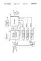
- FIG. 9is a block diagram of the microphone and speech processor portions of a pulsatile type, multi-channel cochlear implant system in accordance with this invention.
- the cochlear implant system of this inventioncomprises several components.
- An electrode array 1is implanted into the cochlea.
- the electrode array 1comprises a number of rings or bands of platinum molded with a flexible silastic carrier. Preferably, there are 32 bands of platinum in total.
- the distal 22 bandsare active electrodes, and have connecting wires welded to them.
- the proximal 10 electrode bandsare used for stiffening, and to act as an aid to surgical insertion.
- the electrode ringsare about 0.05 mm in thickness with a width of 0.3 mm, and have outside diameters ranging from 0.6 mm at the proximal end to 0.4 mm diameter at the distal end.
- the diameter of the ringschanges smoothly so that the array is tapered over the distal 10 mm or so.
- the ringsare spaced on 0.75 mm centers over the distal 25 mm of the electrode array, and all of the exposed outside area of the rings is used as active electrode area.
- the silastic materialmay be MDX4-4210, manufactured by Dow Corning.
- the 22 electrode wirespass via a cable 2 from the electrode array 1 to the receiver-stimulator unit (RSU) 3.
- the invention describedis not limited to the use of this design of electrode array, and a number of alternative electrode designs as have been described in the prior art could be used.
- the RSU 3receives information and power from an external source through a tuned receiving coil 5 attached to the RSU and positioned just beneath the skin.
- the RSUalso provides electrical stimulating pulses to the electrode array 1.
- the power, and data on which electrode to stimulate, and with what intensity,is transmitted across the skin using an inductive link 6 operating at radio frequencies, from an external multipeak speech processor (MSP) 7.
- MSPmultipeak speech processor
- the MSPpicks up acoustic stimuli from a microphone 8 conveniently worn, and extracts from the signal, information which is used to determine stimulation electrode, rate and amplitude.
- the MSPhas a random access memory (RAM) which is programmed to suit each patient.
- RAMrandom access memory
- the patient's response to electrical stimulationis tested some short time after implantation of the RSU 3, using the patient's MSP, and the results of these tests are used to set up the MSP for the patient's own particular requirements. This is done by connecting the MSP, via a connector and cables 9, to a diagnostic programming interface unit (DPI) 10.
- DPIdiagnostic programming interface unit
- the DPIis itself connected via a cable and connector 11 to a general purpose computer referred to as a diagnostic and programming unit (DPU) 12.
- FIGS. 3, 3A and 3BA pictorial representation of the system used by the patient is shown in FIGS. 3, 3A and 3B.
- the electrode array 20is flexible and fits the shape of the cochlea (FIGS. 1A and 1B) as it is inserted along the basilar membrane separating the scala tympani from the remainder of the cochlea.
- the electrode arrayis connected via a silastic-covered cable 21 to the RSU 22. Cable 21 is specially designed to provide stress relief to prevent fracture of the wire in the cable.
- the receiving coil for information and poweris a single turn of multistrand platinum wire 23 which is transformer coupled to the implanted electronics in the RSU 22.
- An externally worn transmitting coil 24is held against the head over the site of the RSU implant 22 by cooperating magnets (not shown) carried adjacent each of the coils 23 and 24, fixture (not shown) attached to the coil 24 for holding the coil to the user's head, or by adhesive tape.
- Coil 24is connected to the speech processor 29 via a coil cable 26 and a hearing aid microphone 27.
- Hearing aid microphone 27is worn on the ear nearest to the implant site and audio data from the microphone 27 is connected via a three wire cable 28 to the MSP 29. Transmission data is connected to the coil 24 from the MSP 29 via the same three wire cable 28 and via the coil cable 26. This three wire arrangement is described in the copending U.S. Pat. Application No. 404,230, filed Sept. 7, 1989, of Christopher N.
- the coil cable 26 and three wire cable 28are attached to the microphone 27 and MSP 29 by demountable connectors 32, 33 and 34.
- the MSP 29is powered by conventionally available batteries (e.g., a single AA size cell) carried inside the MSP 29.
- a plug-in jack 31is provided to allow connection of external audio signal sources, such as from a television, radio, or high quality microphone.
- the pulse which is used to electrically stimulate the cochleais biphasic. That is, it comprises a period of negative current stimulation, followed by an equal period of positive current stimulation of equal amplitude, the two periods (known as phases phi 1 and phi 2), separated by a short period of no stimulation.
- Phi 1 and phi 2may be in the range of 12 to 400 microseconds (typically 200 microseconds), and the intervening interval is typically about 50 microseconds.
- the amplitudes of phi 1 and phi 2their durations, and the duration of the intervening interval are determined by the information decoded from the signal transmitted by the speech processor 29 (FIG. 3).
- the stimulation circuitryis preferably configured as a constant current source. This has the advantage compared to a constant voltage source that if the electrode impedance changes (as has often been observed) the delivered current to the electrode will remain unaltered over a large range of electrode impedances.
- the currentmay be varied from a few microamps to 2 mA, allowing a very large range of loudness percepts to be produced and large variations between patients to be accommodated.
- the stimulus generation circuitry in the RSU 3(FIG. 2) is preferably designed to operate in one of two modes.
- the first modeis referred to as "multipolar" or “common ground” stimulation.
- one electrodeis selected to be the "active” electrode, and all other electrodes operate as a common current source.
- phase phi 2the connections are reversed so that the "active" electrode acts as the current source and the common electrodes act as a current sink.
- the choice of stimulus orderis not determined by any limitations or restrictions in the circuit design, and either way may be chosen when implementing the circuit design.
- the second modeis "bipolar" stimulation.
- stimulationis between two selected electrodes, let us say A and B.
- phase phi 1current is sourced by A, and sunk by B.
- phase phi 2current is sourced by B, and sunk by A, and no other electrodes play any part in stimulation.
- the RSU 3is preferably configured so that any pair of electrodes may be selected for bipolar stimulation. Thus there is great flexibility in choice of stimulation strategy.
- the main aim of this inventionis to provide improved speech communication to those people suffering from profound hearing loss.
- itis also important to be able to convey environmental sounds, for example telephones, doors, warning sirens, door bells, etc., which form part of a person's life.
- the system described up to nowis basically that of the Crosby et al. patent, heretofore referred to and incorporated herein by reference.
- the Crosby et al. patentit is recognized that the second formant F2 carries most of the intelligibility of the speech signal, while the first formant F1, although containing much of the naturalness of the signal, contributes less to intelligibility.
- the Crosby et al. systemalso provides prosodic information in the form of pulse rate. That system compresses the stimulation rate to the range 100-250 Hz.
- Crosby et al.An additional factor employed in Crosby et al. is that only the top 10 to 20 dB of current acoustic stimulus level is used to determine stimulus amplitude. That is, instead of compressing the entire acoustic loudness range into the small range of electrical stimulation available, only the top part is used. Thus, Crosby et al.'s amplitude of the signal is entirely represented by a five bit binary code, which provides only 30 dB of dynamic range.
- the dominant spectral peak in the range of about 800 Hz to about 4000 Hzis used to encode electrode position.
- the amplitude of the dominant spectral peak used to encode electrode positionis used to determine stimulation amplitude.
- Voice pitch (F0)is compressed and used to determine the stimulation rate.
- the Crosby et al. systemstill generates stimuli, but the stimulation rate and electrode position will be determined by the exact nature of the acoustic signal. For example, for sibilant consonants ("s"), the stimulation rate is fairly fast, but not constant, and the electrode stimulated will be one which illicits a high frequency percept.
- ssibilant consonants
- a second speech processing strategyuseful in some patients, is employed in Crosby et al.
- the second strategyis similar to the one mentioned above in that electrode position is encoded from formant frequency.
- the stimulation rateis at the Fl or first formant frequency, and the stimulation amplitude is determined for the value of the peak of the acoustic signal at the time of the F1 peak.
- Thishas the advantage that the stimulation rate is faster, and elicits more natural sounding speech perceptions in some patients.
- the F1 signalis amplitude modulated and temporally better than the F0 rate, the patients also perceive the F0 or voice pitch which is useful for conveying prosodic information.
- Another speech processing strategy considered in the Crosby et al. referenceis to stimulate the patient at the rate of F1 extracted from an incoming speech signal, but to pattern the stimulation such that the stimuli are gated at the F0 rate.
- multichannel cochlear implant prostheses having a pulsatile operating systemare provided with a speech coding scheme in which the speech signal is bandpass filtered into a number of bands, for example 3, within and beyond the normal range of the second frequency peak or formant F2 of the speech signal.
- the speech coding scheme disclosed hereinis referred to as the multi-spectral peak coding strategy (MPEAK).
- MPEAKis designed to provide additional high-frequency information to aid in the perception of speech and environmental sounds.
- the MPEAK coding strategyextracts and codes the F1 and F2 spectral peaks, using the extracted frequency estimates to select a more apical and a more basal pair of electrodes for stimulation. Each selected electrode is stimulated at a pulse rate equal to the fundamental frequency F0. In addition to F1 and F2, three high frequency bands of spectral information are extracted. The amplitude estimates from band three (2000-2800 Hz), band four (2800-4000 Hz), and band five (above 4000 Hz) are presented to fixed electrodes, for example the seventh, fourth and first electrodes, respectively, of the electrode array 1 (FIG. 2).
- the first, fourth and seventh electrodesare selected as the default electrodes for the high-frequency bands because they are spaced far enough apart so that most patients will be able to discriminate between stimulation at these three locations. Note that these default assignments may be reprogrammed as required. If the three high frequency bands were assigned only to the three most basal electrodes in the MAP, many patients might not find the additional high frequency information as useful since patients often do not demonstrate good place-pitch discrimination between adjacent basal electrodes. Additionally, the overall pitch percept resulting from the electrical stimulation might be too high.
- Table Iindicates the frequency ranges of the various formants employed in the speech coding scheme of the present invention.
- the input signalis voiced, it has a fundamental frequency.
- the electrode pairs selected from the estimates of F1, F2 and bands 3 and 4are stimulated sequentially at the rate equal to F0.
- the most basal electrode pairis stimulated first, followed by progressively more apical electrode pairs, as shown in FIG. 5.
- Band 5is not presented in FIG. 5 because negligible information is contained in this frequency band for voiced sounds.
- the electrode pairs selected from the estimates of F2, and bands 3, 4 and 5receive the pulsatile stimulation.
- the rate of stimulationis aperiodic and varies between 200-300 Hz.
- FIG. 6shows the sequential stimulation pattern for an unvoiced sound, with stimulation progressing from base to apex.
- the MPEAK coding strategythus may be seen to extract and code five spectral peaks but only four spectral peaks are encoded for any one stimulus sequence.
- FIG. 7illustrates the pattern of electrical stimulation for various steady state phonemes when using the MPEAK coding strategy.
- a primary function of the MAPis to translate the frequency of the dominant spectral peaks (F1 and F2) to electrode selection. To perform this function, the electrodes are numbered sequentially starting at the round window of the cochlea. Electrode 1 is the most basal electrode and electrode 22 is the most apical in the electrode array. Stimulation of different electrodes normally results in pitch perceptions that reflect the tonotopic organization of the cochlea. Electrode 22 elicits the lowest place-pitch percept, or the "dullest" sound. Electrode 1 elicits the highest place-pitch percept, or "sharpest" sound.
- a default mapping algorithmsplits up the total number of electrodes available to use into a ratio of approximately 1:2, as shown in FIG. 7. Consequently, approximately one third of the electrodes are assigned to the F1 frequency range. These are the more apical electrodes and they will cover the frequency range of 280-1000 Hz. The remaining two thirds of the electrodes are assigned to the F2 frequency range (800-4000 Hz). The most apical electrodes, which cover the frequency range from 280-1000 Hz, are assigned linearly equal frequency bands. The frequency range corresponding to the estimate of F2 is assigned to the remaining more basal electrodes and is divided into logarithmically equal frequency bands. This frequency distribution is called linear/log (lin/log) spacing.
- a second optional mapping algorithmsplits up the total frequency range into logarithmically equal frequency bands for both F1 and F2 electrode groups (log/log spacing). In comparison to the lin/log spacing, this results in relatively broad frequency bands for electrodes that are assigned frequency boundaries below 1000 Hz. Because of the wider frequency bands for these electrodes, many vowel sounds will stimulate similar electrodes, thus making discrimination of these vowels difficult.
- the F1/F2 lin/log function of the default algorithmis preferable because it gives better spatial resolution in the F1 range than the log/log function.
- this algorithmprovides discrimination of vowels and consonants with formants close to 1000 Hz.
- the mapping section of the DPS programallows flexibility in assigning frequency bands to electrodes. If fewer electrodes are included in the MAP, then fewer and wider frequency bands are allocated automatically by the computer so that the entire frequency range is covered. Furthermore, it is possible to override the computer-generated spacing of frequency bands. Any range of frequencies may be allocated to any electrode or electrodes by changing the upper frequency boundaries.
- Table IIshows the default boundaries (lin/log) for a MAP created in the biphasic +1 mode using 20 electrode pairs and the MPEAK coding strategy.
- Table IIIshows the default boundaries in the same mode using only 14 electrode pairs and the MPEAK coding strategy.
- the amplitude of the electrical stimulusis determined from the amplitude of the incoming acoustic signal within each of the five frequency bands (F1, F2, Bands 3, 4 and 5).
- the electrodeshave different threshold (T) and maximum acceptable loudness (C) levels, the speech processor must determine the level of stimulation for each electrode separately based on the amplitude of the incoming signal in each band.
- the MSP(FIG. 2) contains a non-linear loudness growth algorithm that converts acoustic signal amplitude to electrical stimulation parameters.
- the MSPconverts the amplitude of the acoustic signal into a digital linear scale with values from 0 to 150, as may be seen now by reference to FIG. 8. That digital scale (in combination with the T and C-levels stored in the patient's MAP) determines the actual charge delivered to the electrodes. Signals whose amplitude levels are coded as 1 will cause stimulation at the T-level. Signals whose amplitude levels are coded as 150 will cause stimulation at the C-level.
- the system 100includes a microphone 110 which picks up speech and provides electrical audio signals to a speech feature extractor 112 through an automatic gain control amplifier 111.
- the speech feature extractor 112analyzes the signals and provides digital outputs corresponding to the frequencies and amplitudes of the first and second formants, identified as F1, A1, F2 and A2, respectively, in FIG. 10.
- the speech feature extractor 112also detects and outputs the voice pitch FO and starts the encoder 113, which translates, using a MAP 114 containing information on the patient's psychophysical test results, the voice pitch information into a pattern of electrical stimulation on two electrodes that are stimulated sequentially.
- the data so translatedis sent by the patient coil 115 to the implanted receiver stimulator unit RSU 3 (FIG. 2).
- Three bandpass filters 116, 117 and 118also receive the audio signal from microphone 110 before it is applied to the speech feature extractor 112, and separate the signal into three components of different frequencies, a 2000-2800 Hz signal in band 3, a 2800-4000 Hz signal in band 4, and 4000-8000 Hz signal in band 5.
- the signals from bands 3, 4 and 5are lead to the encoder 113 and mapping of these signals is done in a manner similar to that for the first and second formants, and translation of the resulting pattern of electrical stimulation to the appropriate electrodes takes place, as discussed earlier herein.
- the automatic gain control amplifier 111is used to control the amplitude of the signal fed to the filters 116 and 117. Since filter 118 is only used for unvoiced parts of the speech signal, its amplitude is never very great and, therefore, the signal does not require automatic gain control. Accordingly, amplifier 119 does not have automatic gain control provisions incorporated therein.
- the psychophysical measurements that are made using the DPS softwareprovide the information for translating the extracted acoustic input into patient-specific stimulation parameters. Threshold (T) and maximum (C) levels for electrical stimulation are measured for each electrode pair. These values are stored in the MAP. They determine the relationship between the incoming acoustic signal amplitude and the stimulation level for any given electrode pair.
- a random access memorystores a set of number tables, referred to collectively as a MAP.
- the MAPdetermines both stimulus parameters for F1, F2 and bands 3-5, and the amplitude estimates.
- the encoding of the stimulus parametersfollows a sequence of distinct steps. The steps may be summarized as follows:
- the first formant frequency (F1)is converted to a number based on the dominant spectral peak in the region between 280-1000 Hz.
- the F1 numberis used, in conjunction with one of the MAP tables, to determine the electrode to be stimulated to represent the first formant.
- the indifferent electrodeis determined by the mode.
- the second formant frequency (F2)is converted to a number based on the dominant spectral peak in region between 800-4000 Hz.
- the F2 numberis used, in conjunction with one of the MAP tables to determine the electrode to be stimulated to represent the second formant.
- the indifferent electrodeis determined by the mode.
- the amplitude estimates for bands 3, 4 and 5are assigned to the three default electrodes 7, 4 and 1 for bands 3, 4 and 5, respectively, or such other electrodes that may be selected when the MAP is being prepared.
- the amplitude of the acoustic signal in each of the frequency bandsis converted to a number ranging from 0-150.
- the level of stimulation that will be deliveredis determined by referring to a set MAP tables that relate acoustic amplitude (in range of 0-150) to stimulation level for the specific electrodes selected in steps 2, 4 and 5, above.
- the dataare further encoded in the speech processor and transmitted to the receiver/stimulator. It, in turn, decodes the data and sends the stimuli to the appropriate electrodes. Stimulus pulses are presented at a rate equal to F0 during voiced periods and at a random aperiodic rate (typically 200 to 300 Hz) during unvoiced periods.
- the multi-spectral peak speech coding scheme of the present inventionprovides all of the information available in the prior art F0F1F2 scheme, while providing additional information from three high frequency band pass filters. These filters cover the following frequency ranges: 2000 to 2800 Hz, 2800 to 4000 Hz and 4000 to 8000 Hz. The energy within these ranges controls the amplitude of electrical stimulation of three fixed electrode pairs in the basal end of the electrode array. Thus, additional information about high frequency sounds is presented at a tonotopically appropriate place within the cochlea.
- the overall stimulation rateremains as FO (fundamental frequency or voice pitch) but in the scheme of the present invention four electrical stimulation pulses occur for each glottal pulse. This compares with the prior F0F1F2 strategy in which only two pulses occur per voice pitch period.
- the two pulses representing the first and second formantare still provided, and additional stimulation pulses occur representing energy in the 2000-2800 Hz and the 2800-4000 Hz ranges.
- this inventionprovides an improved cochlear implant system which overcomes various of the problems associated with earlier cochlear implant systems.
- the use of a multi-spectral peak speech coding strategy in accordance with this inventionprovides the user of the implant system with significantly improved speech recognition, even in the presence of moderate levels of background noise.
- improved recognition of phonemes and environmental soundsare provided by this invention.
Landscapes
- Health & Medical Sciences (AREA)
- Otolaryngology (AREA)
- Engineering & Computer Science (AREA)
- Biomedical Technology (AREA)
- Nuclear Medicine, Radiotherapy & Molecular Imaging (AREA)
- Radiology & Medical Imaging (AREA)
- Life Sciences & Earth Sciences (AREA)
- Animal Behavior & Ethology (AREA)
- General Health & Medical Sciences (AREA)
- Public Health (AREA)
- Veterinary Medicine (AREA)
- Prostheses (AREA)
Abstract
Description
TABLE I ______________________________________ Frequency Range Formant or Band ______________________________________ 280-1000 Hz F1 800-4000 Hz F2 2000-2800 Hz Band 3 - Electrode 7 2800-4000 Hz Band 4 -Electrode 4 4000 Hz and above Band 5 -Electrode 4 ______________________________________
TABLE II ______________________________________ Lin/Log Frequency Boundaries for 20 Electrodes in a BP +1 Mode. Also Shown are the electrode allocations for the three high frequency bands. Frequency Boundaries Electrode Lower Upper ______________________________________ 20 280 400 19 400 500 18 500 600 17 600 700 16 700 800 15 800 900 14 900 1000 13 1000 1112 12 1112 1237 11 1237 1377 10 1377 1531 9 1531 1704 8 1704 1896 7 1896 2109 6 2109 2346 5 2346 2611 4 2611 2904 3 2904 3231 2 3231 3595 1 3595 & above Electrodes: for Band 3 - 7 for Band 4 - 4 for Band 5 - 1 ______________________________________
TABLE III ______________________________________ Lin/Log Frequency Boundaries for 14 Electrodes in a BP +1 Mode. Also shown are the electrode allocations for the three high frequency bands. Frequency Boundaries Electrode Lower Upper ______________________________________ 20 280 400 18 400 550 17 550 700 16 700 850 15 850 1000 14 1000 1166 13 1166 1360 10 1360 1587 9 1587 1851 8 1851 2160 7 2160 2519 6 2519 2939 5 2939 3428 4 3428 & above Electrodes: for Band 3 - 8 for Band 4 - 6 for Band 5 - 4 ______________________________________
Claims (13)
Priority Applications (1)
| Application Number | Priority Date | Filing Date | Title |
|---|---|---|---|
| US07/808,428US5271397A (en) | 1989-09-08 | 1991-12-16 | Multi-peak speech processor |
Applications Claiming Priority (1)
| Application Number | Priority Date | Filing Date | Title |
|---|---|---|---|
| AUPJ624989 | 1989-09-08 |
Related Child Applications (1)
| Application Number | Title | Priority Date | Filing Date |
|---|---|---|---|
| US07/808,428DivisionUS5271397A (en) | 1989-09-08 | 1991-12-16 | Multi-peak speech processor |
Publications (1)
| Publication Number | Publication Date |
|---|---|
| US5095904Atrue US5095904A (en) | 1992-03-17 |
Family
ID=3774177
Family Applications (1)
| Application Number | Title | Priority Date | Filing Date |
|---|---|---|---|
| US07/577,657Expired - LifetimeUS5095904A (en) | 1989-09-08 | 1990-09-04 | Multi-peak speech procession |
Country Status (5)
| Country | Link |
|---|---|
| US (1) | US5095904A (en) |
| EP (1) | EP0450004B1 (en) |
| CA (1) | CA2024845C (en) |
| DE (1) | DE69024479T2 (en) |
| WO (1) | WO1991003913A1 (en) |
Cited By (175)
| Publication number | Priority date | Publication date | Assignee | Title |
|---|---|---|---|---|
| US5215085A (en)* | 1988-06-29 | 1993-06-01 | Erwin Hochmair | Method and apparatus for electrical stimulation of the auditory nerve |
| US5381512A (en)* | 1992-06-24 | 1995-01-10 | Moscom Corporation | Method and apparatus for speech feature recognition based on models of auditory signal processing |
| WO1995001709A1 (en)* | 1993-07-01 | 1995-01-12 | The University Of Melbourne | Cochlear implant devices |
| AU657959B2 (en)* | 1991-07-02 | 1995-03-30 | University Of Melbourne, The | Spectral maxima sound processor |
| US5531787A (en)* | 1993-01-25 | 1996-07-02 | Lesinski; S. George | Implantable auditory system with micromachined microsensor and microactuator |
| US5545191A (en)* | 1994-05-06 | 1996-08-13 | Alfred E. Mann Foundation For Scientific Research | Method for optimally positioning and securing the external unit of a transcutaneous transducer of the skin of a living body |
| US5549658A (en)* | 1994-10-24 | 1996-08-27 | Advanced Bionics Corporation | Four-Channel cochlear system with a passive, non-hermetically sealed implant |
| US5584870A (en)* | 1995-03-09 | 1996-12-17 | Cochlear Ltd. | Implant ESD protection network |
| US5597380A (en)* | 1991-07-02 | 1997-01-28 | Cochlear Ltd. | Spectral maxima sound processor |
| US5601617A (en)* | 1995-04-26 | 1997-02-11 | Advanced Bionics Corporation | Multichannel cochlear prosthesis with flexible control of stimulus waveforms |
| US5603726A (en)* | 1989-09-22 | 1997-02-18 | Alfred E. Mann Foundation For Scientific Research | Multichannel cochlear implant system including wearable speech processor |
| US5626629A (en)* | 1995-05-31 | 1997-05-06 | Advanced Bionics Corporation | Programming of a speech processor for an implantable cochlear stimulator |
| AU681413B2 (en)* | 1993-07-01 | 1997-08-28 | University Of Melbourne, The | Cochlear implant devices |
| US5772575A (en)* | 1995-09-22 | 1998-06-30 | S. George Lesinski | Implantable hearing aid |
| DE19707046A1 (en)* | 1997-02-21 | 1998-08-27 | Rolf Prof Dr Ing Eckmiller | Learnable "Active Vision" implant encoder |
| US5824022A (en)* | 1996-03-07 | 1998-10-20 | Advanced Bionics Corporation | Cochlear stimulation system employing behind-the-ear speech processor with remote control |
| US5876425A (en)* | 1989-09-22 | 1999-03-02 | Advanced Bionics Corporation | Power control loop for implantable tissue stimulator |
| US5881158A (en)* | 1996-05-24 | 1999-03-09 | United States Surgical Corporation | Microphones for an implantable hearing aid |
| US5922017A (en)* | 1996-03-13 | 1999-07-13 | Med-El Elektromedizinische Gerate Gmbh | Device and method for implants in ossified cochleas |
| US5951601A (en)* | 1996-03-25 | 1999-09-14 | Lesinski; S. George | Attaching an implantable hearing aid microactuator |
| US5977689A (en)* | 1996-07-19 | 1999-11-02 | Neukermans; Armand P. | Biocompatible, implantable hearing aid microactuator |
| US6011993A (en)* | 1998-04-30 | 2000-01-04 | Advanced Bionics Corporation | Method of making implanted ceramic case with enhanced ceramic case strength |
| USD419677S (en)* | 1997-11-04 | 2000-01-25 | Med-El Elektromedizinische Gerate Ges.M.B.H. | Speech processor for use with a cochlear implant |
| US6068589A (en)* | 1996-02-15 | 2000-05-30 | Neukermans; Armand P. | Biocompatible fully implantable hearing aid transducers |
| US6078838A (en)* | 1998-02-13 | 2000-06-20 | University Of Iowa Research Foundation | Pseudospontaneous neural stimulation system and method |
| US6103033A (en) | 1998-03-04 | 2000-08-15 | Therasense, Inc. | Process for producing an electrochemical biosensor |
| DE19915846C1 (en)* | 1999-04-08 | 2000-08-31 | Implex Hear Tech Ag | Partially implantable system for rehabilitating hearing trouble includes a cordless telemetry device to transfer data between an implantable part, an external unit and an energy supply. |
| US6120676A (en) | 1997-02-06 | 2000-09-19 | Therasense, Inc. | Method of using a small volume in vitro analyte sensor |
| US6134461A (en) | 1998-03-04 | 2000-10-17 | E. Heller & Company | Electrochemical analyte |
| US6162611A (en) | 1993-12-02 | 2000-12-19 | E. Heller & Company | Subcutaneous glucose electrode |
| US6175752B1 (en) | 1998-04-30 | 2001-01-16 | Therasense, Inc. | Analyte monitoring device and methods of use |
| US6219580B1 (en) | 1995-04-26 | 2001-04-17 | Advanced Bionics Corporation | Multichannel cochlear prosthesis with flexible control of stimulus waveforms |
| US6249704B1 (en)* | 1998-08-11 | 2001-06-19 | Advanced Bionics Corporation | Low voltage stimulation to elicit stochastic response patterns that enhance the effectiveness of a cochlear implant |
| US6289247B1 (en) | 1998-06-02 | 2001-09-11 | Advanced Bionics Corporation | Strategy selector for multichannel cochlear prosthesis |
| US20020012438A1 (en)* | 2000-06-30 | 2002-01-31 | Hans Leysieffer | System for rehabilitation of a hearing disorder |
| US6358054B1 (en)* | 1995-05-24 | 2002-03-19 | Syracuse Language Systems | Method and apparatus for teaching prosodic features of speech |
| US20020048374A1 (en)* | 2000-06-01 | 2002-04-25 | Sigfrid Soli | Method and apparatus for measuring the performance of an implantable middle ear hearing aid, and the respones of a patient wearing such a hearing aid |
| US20020051550A1 (en)* | 2000-08-25 | 2002-05-02 | Hans Leysieffer | Implantable hermetically sealed housing for an implantable medical device and process for producing the same |
| US6411854B1 (en) | 1998-04-30 | 2002-06-25 | Advanced Bionics Corporation | Implanted ceramic case with enhanced ceramic case strength |
| US6453283B1 (en)* | 1998-05-11 | 2002-09-17 | Koninklijke Philips Electronics N.V. | Speech coding based on determining a noise contribution from a phase change |
| US6480820B1 (en) | 1999-09-20 | 2002-11-12 | Advanced Cochlear Systems, Inc. | Method of processing auditory data |
| US20030036782A1 (en)* | 2001-08-20 | 2003-02-20 | Hartley Lee F. | BioNet for bilateral cochlear implant systems |
| US6537200B2 (en) | 2000-03-28 | 2003-03-25 | Cochlear Limited | Partially or fully implantable hearing system |
| USD473652S1 (en) | 2001-06-07 | 2003-04-22 | Cochlear Limited | Speech processor for a cochlear implant |
| USD473946S1 (en) | 2001-06-07 | 2003-04-29 | Cochlear Limited | Speech processor with hook for a cochlear implant |
| US6565503B2 (en) | 2000-04-13 | 2003-05-20 | Cochlear Limited | At least partially implantable system for rehabilitation of hearing disorder |
| US6575894B2 (en) | 2000-04-13 | 2003-06-10 | Cochlear Limited | At least partially implantable system for rehabilitation of a hearing disorder |
| US20030167077A1 (en)* | 2000-08-21 | 2003-09-04 | Blamey Peter John | Sound-processing strategy for cochlear implants |
| US6629923B2 (en) | 2000-09-21 | 2003-10-07 | Phonak Ag | At least partially implantable hearing system with direct mechanical stimulation of a lymphatic space of the inner ear |
| US6631295B2 (en) | 1998-02-13 | 2003-10-07 | University Of Iowa Research Foundation | System and method for diagnosing and/or reducing tinnitus |
| US20040015204A1 (en)* | 2002-06-20 | 2004-01-22 | Whitehurst Todd K. | Implantable microstimulators and methods for unidirectional propagation of action potentials |
| US20040015205A1 (en)* | 2002-06-20 | 2004-01-22 | Whitehurst Todd K. | Implantable microstimulators with programmable multielectrode configuration and uses thereof |
| US6697674B2 (en) | 2000-04-13 | 2004-02-24 | Cochlear Limited | At least partially implantable system for rehabilitation of a hearing disorder |
| US20040082980A1 (en)* | 2000-10-19 | 2004-04-29 | Jaouhar Mouine | Programmable neurostimulator |
| US6736770B2 (en) | 2000-08-25 | 2004-05-18 | Cochlear Limited | Implantable medical device comprising an hermetically sealed housing |
| US20050033377A1 (en)* | 2001-11-09 | 2005-02-10 | Dusan Milojevic | Subthreshold stimulation of a cochlea |
| US20050107845A1 (en)* | 2003-03-11 | 2005-05-19 | Wakefield Gregory H. | Using a genetic algorithm to fit a cochlear implant system to a patient |
| US6907130B1 (en) | 1998-02-13 | 2005-06-14 | University Of Iowa Research Foundation | Speech processing system and method using pseudospontaneous stimulation |
| US20050177205A1 (en)* | 2004-01-09 | 2005-08-11 | Bomjun Kwon | Stimulation mode for cochlear implant speech coding |
| US20050203557A1 (en)* | 2001-10-30 | 2005-09-15 | Lesinski S. G. | Implantation method for a hearing aid microactuator implanted into the cochlea |
| US7010354B1 (en)* | 1999-09-02 | 2006-03-07 | The Bionic Ear Institute | Sound processor for cochlear implants |
| US20060169599A1 (en)* | 1998-10-08 | 2006-08-03 | Therasense, Inc. | Small volume in vitro analyte sensor |
| US20060212094A1 (en)* | 2004-12-31 | 2006-09-21 | Ludwig Moser | Middle ear multi-channel electrode |
| US7130694B1 (en) | 2001-12-26 | 2006-10-31 | Advanced Bionics Corporation | Pulse skipping strategy |
| US20060247488A1 (en)* | 2005-04-27 | 2006-11-02 | Bernd Waldmann | Implantable hearing aid actuator positioning |
| US20060265061A1 (en)* | 2005-05-19 | 2006-11-23 | Cochlear Limited | Independent and concurrent processing multiple audio input signals in a prosthetic hearing implant |
| US7155289B1 (en) | 2001-08-17 | 2006-12-26 | Advanced Bionics Corporation | Auto-referencing mixed mode phase locked loop for audio playback applications |
| US20060292524A1 (en)* | 2005-06-27 | 2006-12-28 | Giorgio Lorenzon | Dental prosthesis implant construction |
| US20070027676A1 (en)* | 2005-04-13 | 2007-02-01 | Cochlear Limited | Recording and retrieval of sound data in a hearing prosthesis |
| US20070106135A1 (en)* | 2005-11-04 | 2007-05-10 | Abbott Diabetes Care, Inc. | Method and system for providing basal profile modification in analyte monitoring and management systems |
| US20070106712A1 (en)* | 2005-11-04 | 2007-05-10 | Nec Corporation | Replication arbitration apparatus, method and program |
| US20070123938A1 (en)* | 2005-11-30 | 2007-05-31 | Haller Matthew I | Magnetically coupled microstimulators |
| US20070198067A1 (en)* | 2005-10-27 | 2007-08-23 | Cochlear Limited | Automated collection of operational data from distributed medical devices |
| US20070270922A1 (en)* | 2006-05-18 | 2007-11-22 | Clemens Zierhofer | Implanted system with dc free inputs and outputs |
| US20080004512A1 (en)* | 2002-11-05 | 2008-01-03 | Funderburk Jeffery V | Sensor inserter assembly |
| US20080041506A1 (en)* | 2006-08-19 | 2008-02-21 | Aijun Huang | Alloy and method of treating titanium aluminide |
| US20080065173A1 (en)* | 2003-05-16 | 2008-03-13 | Medtronic, Inc. | Headset recharger for cranially implantable medical devices |
| US20080177353A1 (en)* | 2006-12-28 | 2008-07-24 | Takashi Hirota | Cochlear implant device, extracorporeal sound collector, and cochlear implant system having the same |
| US20080198947A1 (en)* | 2007-02-15 | 2008-08-21 | Zierhofer Clemens M | Inductive Power and Data Transmission System Based on Class D and Amplitude Shift Keying |
| US20080234783A1 (en)* | 2007-03-21 | 2008-09-25 | Cochlear Americas | Stimulating auditory nerve fibers to provide pitch representation |
| US20080249584A1 (en)* | 2007-04-05 | 2008-10-09 | Cardiac Pacemakers, Inc. | Method and device for cardiosympathetic inhibition |
| US20090005836A1 (en)* | 2006-07-21 | 2009-01-01 | Material Solutions Technology Co., Ltd | Cochlear Implant |
| US20090157143A1 (en)* | 2005-09-19 | 2009-06-18 | Fraunhofer-Gesellschaft Zur Foerderung Der Angewandten Forschung E.V. | Cochlear implant, device for generating a control signal for a cochlear implant, device for generating a combination signal and combination signal and corresponding methods |
| US20090171182A1 (en)* | 2004-12-29 | 2009-07-02 | Abbott Diabetes Care Inc. | Method and apparatus for mounting a data transmission device in a communication system |
| US20090240307A1 (en)* | 2008-01-22 | 2009-09-24 | Cochlear Limited | Recipient-controlled fitting of a hearing prosthesis |
| US7620438B2 (en) | 2006-03-31 | 2009-11-17 | Abbott Diabetes Care Inc. | Method and system for powering an electronic device |
| US7627383B2 (en) | 2005-03-15 | 2009-12-01 | Boston Scientific Neuromodulation Corporation | Implantable stimulator |
| US20100030130A1 (en)* | 2001-11-09 | 2010-02-04 | Cochlear Limited | Pharmaceutical intervention for modulation of neural plasticity |
| US20100152813A1 (en)* | 2003-03-11 | 2010-06-17 | Cochlear Limited | Using a genetic algorithm to fit a medical implant system to a patient |
| US7811231B2 (en) | 2002-12-31 | 2010-10-12 | Abbott Diabetes Care Inc. | Continuous glucose monitoring system and methods of use |
| US20100280307A1 (en)* | 2003-03-11 | 2010-11-04 | Sean Lineaweaver | Using a genetic algorithm in mixed mode device |
| US20100292759A1 (en)* | 2005-03-24 | 2010-11-18 | Hahn Tae W | Magnetic field sensor for magnetically-coupled medical implant devices |
| US7877136B1 (en) | 2007-09-28 | 2011-01-25 | Boston Scientific Neuromodulation Corporation | Enhancement of neural signal transmission through damaged neural tissue via hyperpolarizing electrical stimulation current |
| US20110054275A1 (en)* | 2009-08-31 | 2011-03-03 | Abbott Diabetes Care Inc. | Mounting Unit Having a Sensor and Associated Circuitry |
| US20110060196A1 (en)* | 2009-08-31 | 2011-03-10 | Abbott Diabetes Care Inc. | Flexible Mounting Unit and Cover for a Medical Device |
| US20110060702A1 (en)* | 2009-09-10 | 2011-03-10 | Cochlear Limited, IP Department | Using a genetic algorithm employing an expedited convergence mechanism |
| US20110060383A1 (en)* | 2009-09-10 | 2011-03-10 | Cochlear Limited, IP Department | Using a genetic algorithm employing dynamic mutation |
| US20110077710A1 (en)* | 2009-09-29 | 2011-03-31 | Advanced Bionics, Llc | Methods and Systems for Representing Different Spectral Components of an Audio Signal Presented to a Cochlear Implant Patient |
| US7920907B2 (en) | 2006-06-07 | 2011-04-05 | Abbott Diabetes Care Inc. | Analyte monitoring system and method |
| US7928850B2 (en) | 2007-05-08 | 2011-04-19 | Abbott Diabetes Care Inc. | Analyte monitoring system and methods |
| US7976778B2 (en) | 2001-04-02 | 2011-07-12 | Abbott Diabetes Care Inc. | Blood glucose tracking apparatus |
| US20110270014A1 (en)* | 2010-04-30 | 2011-11-03 | Cochlear Limited | Hearing prosthesis having an on-board fitting system |
| US8066639B2 (en) | 2003-06-10 | 2011-11-29 | Abbott Diabetes Care Inc. | Glucose measuring device for use in personal area network |
| US8103456B2 (en) | 2009-01-29 | 2012-01-24 | Abbott Diabetes Care Inc. | Method and device for early signal attenuation detection using blood glucose measurements |
| US8112240B2 (en) | 2005-04-29 | 2012-02-07 | Abbott Diabetes Care Inc. | Method and apparatus for providing leak detection in data monitoring and management systems |
| US8121699B1 (en)* | 2005-03-14 | 2012-02-21 | Advanced Bionics | Sound processing and stimulation systems and methods for use with cochlear implant devices |
| US8123686B2 (en) | 2007-03-01 | 2012-02-28 | Abbott Diabetes Care Inc. | Method and apparatus for providing rolling data in communication systems |
| US8149117B2 (en) | 2007-05-08 | 2012-04-03 | Abbott Diabetes Care Inc. | Analyte monitoring system and methods |
| US8226891B2 (en) | 2006-03-31 | 2012-07-24 | Abbott Diabetes Care Inc. | Analyte monitoring devices and methods therefor |
| US8287454B2 (en) | 1998-04-30 | 2012-10-16 | Abbott Diabetes Care Inc. | Analyte monitoring device and methods of use |
| US8333714B2 (en) | 2006-09-10 | 2012-12-18 | Abbott Diabetes Care Inc. | Method and system for providing an integrated analyte sensor insertion device and data processing unit |
| US8346337B2 (en) | 1998-04-30 | 2013-01-01 | Abbott Diabetes Care Inc. | Analyte monitoring device and methods of use |
| US20130023963A1 (en)* | 2011-07-22 | 2013-01-24 | Lockheed Martin Corporation | Cochlear implant using optical stimulation with encoded information designed to limit heating effects |
| US8414749B2 (en) | 1991-03-04 | 2013-04-09 | Abbott Diabetes Care Inc. | Subcutaneous glucose electrode |
| USD683029S1 (en) | 2010-12-17 | 2013-05-21 | Advanced Bionics, Llc | Sound processor |
| US8456301B2 (en) | 2007-05-08 | 2013-06-04 | Abbott Diabetes Care Inc. | Analyte monitoring system and methods |
| US8465425B2 (en) | 1998-04-30 | 2013-06-18 | Abbott Diabetes Care Inc. | Analyte monitoring device and methods of use |
| US8512243B2 (en) | 2005-09-30 | 2013-08-20 | Abbott Diabetes Care Inc. | Integrated introducer and transmitter assembly and methods of use |
| US8545403B2 (en) | 2005-12-28 | 2013-10-01 | Abbott Diabetes Care Inc. | Medical device insertion |
| US8602991B2 (en) | 2005-08-30 | 2013-12-10 | Abbott Diabetes Care Inc. | Analyte sensor introducer and methods of use |
| US8612159B2 (en) | 1998-04-30 | 2013-12-17 | Abbott Diabetes Care Inc. | Analyte monitoring device and methods of use |
| US8613703B2 (en) | 2007-05-31 | 2013-12-24 | Abbott Diabetes Care Inc. | Insertion devices and methods |
| US8652043B2 (en) | 2001-01-02 | 2014-02-18 | Abbott Diabetes Care Inc. | Analyte monitoring device and methods of use |
| US8665091B2 (en) | 2007-05-08 | 2014-03-04 | Abbott Diabetes Care Inc. | Method and device for determining elapsed sensor life |
| US8688188B2 (en) | 1998-04-30 | 2014-04-01 | Abbott Diabetes Care Inc. | Analyte monitoring device and methods of use |
| US8732188B2 (en) | 2007-02-18 | 2014-05-20 | Abbott Diabetes Care Inc. | Method and system for providing contextual based medication dosage determination |
| WO2013055940A3 (en)* | 2011-10-11 | 2014-05-30 | Duke University | Non-regular electrical stimulation patterns for treating neurological disorders |
| US8764657B2 (en) | 2010-03-24 | 2014-07-01 | Abbott Diabetes Care Inc. | Medical device inserters and processes of inserting and using medical devices |
| US8771183B2 (en) | 2004-02-17 | 2014-07-08 | Abbott Diabetes Care Inc. | Method and system for providing data communication in continuous glucose monitoring and management system |
| US20140207456A1 (en)* | 2010-09-23 | 2014-07-24 | Waveform Communications, Llc | Waveform analysis of speech |
| US8852101B2 (en) | 2005-12-28 | 2014-10-07 | Abbott Diabetes Care Inc. | Method and apparatus for providing analyte sensor insertion |
| US8923981B2 (en) | 2008-10-03 | 2014-12-30 | Duke University | Non-regular electrical stimulation patterns designed with a cost function for treating neurological disorders |
| US8930203B2 (en) | 2007-02-18 | 2015-01-06 | Abbott Diabetes Care Inc. | Multi-function analyte test device and methods therefor |
| US8965520B2 (en) | 2004-06-15 | 2015-02-24 | Cochlear Limited | Automatic determination of the threshold of an evoked neural response |
| US8974386B2 (en) | 1998-04-30 | 2015-03-10 | Abbott Diabetes Care Inc. | Analyte monitoring device and methods of use |
| US8993331B2 (en) | 2009-08-31 | 2015-03-31 | Abbott Diabetes Care Inc. | Analyte monitoring system and methods for managing power and noise |
| US9066695B2 (en) | 1998-04-30 | 2015-06-30 | Abbott Diabetes Care Inc. | Analyte monitoring device and methods of use |
| US9226701B2 (en) | 2009-04-28 | 2016-01-05 | Abbott Diabetes Care Inc. | Error detection in critical repeating data in a wireless sensor system |
| US9259579B2 (en) | 2008-10-03 | 2016-02-16 | Duke University | Non-regular electrical stimulation patterns for treating neurological disorders using a cost function |
| US9259175B2 (en) | 2006-10-23 | 2016-02-16 | Abbott Diabetes Care, Inc. | Flexible patch for fluid delivery and monitoring body analytes |
| US9314195B2 (en) | 2009-08-31 | 2016-04-19 | Abbott Diabetes Care Inc. | Analyte signal processing device and methods |
| US9320461B2 (en) | 2009-09-29 | 2016-04-26 | Abbott Diabetes Care Inc. | Method and apparatus for providing notification function in analyte monitoring systems |
| US9339649B2 (en) | 2012-03-12 | 2016-05-17 | The Hospital For Sick Children | Implantable cochlear systems with intracochlear electrode array for balance stabilization |
| US9351669B2 (en) | 2009-09-30 | 2016-05-31 | Abbott Diabetes Care Inc. | Interconnect for on-body analyte monitoring device |
| US9393432B2 (en) | 2008-10-31 | 2016-07-19 | Medtronic, Inc. | Non-hermetic direct current interconnect |
| US9398882B2 (en) | 2005-09-30 | 2016-07-26 | Abbott Diabetes Care Inc. | Method and apparatus for providing analyte sensor and data processing device |
| US9402544B2 (en) | 2009-02-03 | 2016-08-02 | Abbott Diabetes Care Inc. | Analyte sensor and apparatus for insertion of the sensor |
| US9402570B2 (en) | 2011-12-11 | 2016-08-02 | Abbott Diabetes Care Inc. | Analyte sensor devices, connections, and methods |
| US20160317810A1 (en)* | 2003-05-08 | 2016-11-03 | Advanced Bionics Ag | Cochlear implant headpiece |
| US9521968B2 (en) | 2005-09-30 | 2016-12-20 | Abbott Diabetes Care Inc. | Analyte sensor retention mechanism and methods of use |
| US20170001019A1 (en)* | 2008-05-15 | 2017-01-05 | Boston Scientific Neuromodulation Corporation | Fractionalized Stimulation Pulses in an Implantable Stimulator Device |
| US9572534B2 (en) | 2010-06-29 | 2017-02-21 | Abbott Diabetes Care Inc. | Devices, systems and methods for on-skin or on-body mounting of medical devices |
| US9743862B2 (en) | 2011-03-31 | 2017-08-29 | Abbott Diabetes Care Inc. | Systems and methods for transcutaneously implanting medical devices |
| US9788771B2 (en) | 2006-10-23 | 2017-10-17 | Abbott Diabetes Care Inc. | Variable speed sensor insertion devices and methods of use |
| US9802046B2 (en) | 2008-10-03 | 2017-10-31 | Duke University | Non-regular electrical stimulation patterns for improved efficiency in treating Parkinson's Disease |
| US9968306B2 (en) | 2012-09-17 | 2018-05-15 | Abbott Diabetes Care Inc. | Methods and apparatuses for providing adverse condition notification with enhanced wireless communication range in analyte monitoring systems |
| US9980669B2 (en) | 2011-11-07 | 2018-05-29 | Abbott Diabetes Care Inc. | Analyte monitoring device and methods |
| US10028680B2 (en) | 2006-04-28 | 2018-07-24 | Abbott Diabetes Care Inc. | Introducer assembly and methods of use |
| US10065464B2 (en) | 2008-10-03 | 2018-09-04 | Duke University | Medical stimulation device providing non-regular electrical stimulation patterns for treating neurological disorders |
| CN108721777A (en)* | 2017-04-21 | 2018-11-02 | 财团法人交大思源基金会 | Artificial electronic ear device and stimulation method thereof |
| US10194863B2 (en) | 2005-09-30 | 2019-02-05 | Abbott Diabetes Care Inc. | Integrated transmitter unit and sensor introducer mechanism and methods of use |
| US10213139B2 (en) | 2015-05-14 | 2019-02-26 | Abbott Diabetes Care Inc. | Systems, devices, and methods for assembling an applicator and sensor control device |
| US10226207B2 (en) | 2004-12-29 | 2019-03-12 | Abbott Diabetes Care Inc. | Sensor inserter having introducer |
| US10674944B2 (en) | 2015-05-14 | 2020-06-09 | Abbott Diabetes Care Inc. | Compact medical device inserters and related systems and methods |
| US10688306B2 (en) | 2013-12-23 | 2020-06-23 | Deep Brain Innovations LLC | Programming systems for deep brain stimulator system |
| US10744328B2 (en) | 2010-05-27 | 2020-08-18 | Duke University | System for generating and applying waveform shapes for treating neurological disorders optimized for energy efficiency |
| USD902408S1 (en) | 2003-11-05 | 2020-11-17 | Abbott Diabetes Care Inc. | Analyte sensor control unit |
| US10874338B2 (en) | 2010-06-29 | 2020-12-29 | Abbott Diabetes Care Inc. | Devices, systems and methods for on-skin or on-body mounting of medical devices |
| US11013924B2 (en) | 2008-10-03 | 2021-05-25 | Duke University | Non-regular electrical stimulation patterns for treating neurological disorders |
| USD924406S1 (en) | 2010-02-01 | 2021-07-06 | Abbott Diabetes Care Inc. | Analyte sensor inserter |
| US11071478B2 (en) | 2017-01-23 | 2021-07-27 | Abbott Diabetes Care Inc. | Systems, devices and methods for analyte sensor insertion |
| US11298058B2 (en) | 2005-12-28 | 2022-04-12 | Abbott Diabetes Care Inc. | Method and apparatus for providing analyte sensor insertion |
| US11583680B2 (en) | 2013-05-22 | 2023-02-21 | Deep Brain Innovations LLC | Deep brain stimulator and method of use |
| US11793936B2 (en) | 2009-05-29 | 2023-10-24 | Abbott Diabetes Care Inc. | Medical device antenna systems having external antenna configurations |
| US12239463B2 (en) | 2020-08-31 | 2025-03-04 | Abbott Diabetes Care Inc. | Systems, devices, and methods for analyte sensor insertion |
Families Citing this family (11)
| Publication number | Priority date | Publication date | Assignee | Title |
|---|---|---|---|---|
| AUPM883794A0 (en)* | 1994-10-17 | 1994-11-10 | University Of Melbourne, The | Multiple pulse stimulation |
| AU708391B2 (en)* | 1994-10-17 | 1999-08-05 | University Of Melbourne, The | Multiple pulse stimulation |
| US5991663A (en)* | 1995-10-17 | 1999-11-23 | The University Of Melbourne | Multiple pulse stimulation |
| FR2762180B1 (en)* | 1997-04-15 | 1999-05-07 | Roland Roger Carrat | METHOD AND DEVICE FOR AMPLIFYING AND ENCODING THE VOICE SIGNAL FOR IMPROVING INTELLIGIBILITY IN A NOISE ENVIRONMENT AND FOR CORRECTING DEAFNESSES |
| AUPO709197A0 (en) | 1997-05-30 | 1997-06-26 | University Of Melbourne, The | Improvements in electrotactile vocoders |
| CA2328953A1 (en)* | 1999-02-16 | 2000-08-24 | Yugen Kaisha Gm&M | Speech converting device and method |
| AUPS259002A0 (en)* | 2002-05-27 | 2002-06-13 | Bionic Ear Institute, The | Generation of electrical stimuli for application to a cochlea |
| US7787956B2 (en) | 2002-05-27 | 2010-08-31 | The Bionic Ear Institute | Generation of electrical stimuli for application to a cochlea |
| JP5032122B2 (en) | 2003-12-10 | 2012-09-26 | ザ バイオニック イヤ インスティテュート | Delayed stimulation in auditory prostheses |
| DE102016214745B4 (en) | 2016-08-09 | 2018-06-14 | Carl Von Ossietzky Universität Oldenburg | Method for stimulating an implanted electrode arrangement of a hearing prosthesis |
| EP3957358B1 (en)* | 2020-08-21 | 2025-04-02 | Cochlear Limited | Cochlear implant system with optimized frame coding |
Citations (16)
| Publication number | Priority date | Publication date | Assignee | Title |
|---|---|---|---|---|
| US3449768A (en)* | 1966-12-27 | 1969-06-17 | James H Doyle | Artificial sense organ |
| US3751605A (en)* | 1972-02-04 | 1973-08-07 | Beckman Instruments Inc | Method for inducing hearing |
| US3752939A (en)* | 1972-02-04 | 1973-08-14 | Beckman Instruments Inc | Prosthetic device for the deaf |
| US4063048A (en)* | 1977-03-16 | 1977-12-13 | Kissiah Jr Adam M | Implantable electronic hearing aid |
| EP0001915A1 (en)* | 1977-11-03 | 1979-05-16 | The University Of Melbourne | Hearing prosthesis |
| US4207441A (en)* | 1977-03-16 | 1980-06-10 | Bertin & Cie | Auditory prosthesis equipment |
| US4284856A (en)* | 1979-09-24 | 1981-08-18 | Hochmair Ingeborg | Multi-frequency system and method for enhancing auditory stimulation and the like |
| US4357497A (en)* | 1979-09-24 | 1982-11-02 | Hochmair Ingeborg | System for enhancing auditory stimulation and the like |
| US4419995A (en)* | 1981-09-18 | 1983-12-13 | Hochmair Ingeborg | Single channel auditory stimulation system |
| US4499339A (en)* | 1982-11-24 | 1985-02-12 | Baptist Medical Center Of Oklahoma, Inc. | Amplitude modulation apparatus and method |
| US4515158A (en)* | 1980-12-12 | 1985-05-07 | The Commonwealth Of Australia Secretary Of Industry And Commerce | Speech processing method and apparatus |
| US4532930A (en)* | 1983-04-11 | 1985-08-06 | Commonwealth Of Australia, Dept. Of Science & Technology | Cochlear implant system for an auditory prosthesis |
| US4593696A (en)* | 1985-01-17 | 1986-06-10 | Hochmair Ingeborg | Auditory stimulation using CW and pulsed signals |
| US4813417A (en)* | 1987-03-13 | 1989-03-21 | Minnesota Mining And Manufacturing Company | Signal processor for and an auditory prosthesis utilizing channel dominance |
| WO1990000040A1 (en)* | 1988-06-29 | 1990-01-11 | Wallenberg Pachaly E L Von | Process and device for electrical stimulation of the auditory nerve |
| US4918745A (en)* | 1987-10-09 | 1990-04-17 | Storz Instrument Company | Multi-channel cochlear implant system |
Family Cites Families (6)
| Publication number | Priority date | Publication date | Assignee | Title |
|---|---|---|---|---|
| US4039754A (en)* | 1975-04-09 | 1977-08-02 | The United States Of America As Represented By The Administrator Of The National Aeronautics And Space Administration | Speech analyzer |
| US4400590A (en)* | 1980-12-22 | 1983-08-23 | The Regents Of The University Of California | Apparatus for multichannel cochlear implant hearing aid system |
| AU562749B2 (en)* | 1982-08-20 | 1987-06-18 | University Of Melbourne, The | Hearing prosthesis |
| DE3420244A1 (en)* | 1984-05-30 | 1985-12-05 | Hortmann GmbH, 7449 Neckartenzlingen | MULTI-FREQUENCY TRANSMISSION SYSTEM FOR IMPLANTED HEARING PROSTHESES |
| AU569636B2 (en)* | 1984-09-07 | 1988-02-11 | University Of Melbourne, The | Bipolar paired pulse supplied prosthetic device |
| US4592359A (en)* | 1985-04-02 | 1986-06-03 | The Board Of Trustees Of The Leland Stanford Junior University | Multi-channel implantable neural stimulator |
- 1990
- 1990-09-04USUS07/577,657patent/US5095904A/ennot_activeExpired - Lifetime
- 1990-09-07WOPCT/AU1990/000407patent/WO1991003913A1/enactiveIP Right Grant
- 1990-09-07DEDE69024479Tpatent/DE69024479T2/ennot_activeExpired - Fee Related
- 1990-09-07CACA002024845Apatent/CA2024845C/ennot_activeExpired - Fee Related
- 1990-09-07EPEP90913330Apatent/EP0450004B1/ennot_activeExpired - Lifetime
Patent Citations (17)
| Publication number | Priority date | Publication date | Assignee | Title |
|---|---|---|---|---|
| US3449768A (en)* | 1966-12-27 | 1969-06-17 | James H Doyle | Artificial sense organ |
| US3751605A (en)* | 1972-02-04 | 1973-08-07 | Beckman Instruments Inc | Method for inducing hearing |
| US3752939A (en)* | 1972-02-04 | 1973-08-14 | Beckman Instruments Inc | Prosthetic device for the deaf |
| US4063048A (en)* | 1977-03-16 | 1977-12-13 | Kissiah Jr Adam M | Implantable electronic hearing aid |
| US4207441A (en)* | 1977-03-16 | 1980-06-10 | Bertin & Cie | Auditory prosthesis equipment |
| EP0001915A1 (en)* | 1977-11-03 | 1979-05-16 | The University Of Melbourne | Hearing prosthesis |
| US4267410A (en)* | 1977-11-03 | 1981-05-12 | The University Of Melbourne | Prosthesis |
| US4357497A (en)* | 1979-09-24 | 1982-11-02 | Hochmair Ingeborg | System for enhancing auditory stimulation and the like |
| US4284856A (en)* | 1979-09-24 | 1981-08-18 | Hochmair Ingeborg | Multi-frequency system and method for enhancing auditory stimulation and the like |
| US4515158A (en)* | 1980-12-12 | 1985-05-07 | The Commonwealth Of Australia Secretary Of Industry And Commerce | Speech processing method and apparatus |
| US4419995A (en)* | 1981-09-18 | 1983-12-13 | Hochmair Ingeborg | Single channel auditory stimulation system |
| US4499339A (en)* | 1982-11-24 | 1985-02-12 | Baptist Medical Center Of Oklahoma, Inc. | Amplitude modulation apparatus and method |
| US4532930A (en)* | 1983-04-11 | 1985-08-06 | Commonwealth Of Australia, Dept. Of Science & Technology | Cochlear implant system for an auditory prosthesis |
| US4593696A (en)* | 1985-01-17 | 1986-06-10 | Hochmair Ingeborg | Auditory stimulation using CW and pulsed signals |
| US4813417A (en)* | 1987-03-13 | 1989-03-21 | Minnesota Mining And Manufacturing Company | Signal processor for and an auditory prosthesis utilizing channel dominance |
| US4918745A (en)* | 1987-10-09 | 1990-04-17 | Storz Instrument Company | Multi-channel cochlear implant system |
| WO1990000040A1 (en)* | 1988-06-29 | 1990-01-11 | Wallenberg Pachaly E L Von | Process and device for electrical stimulation of the auditory nerve |
Non-Patent Citations (6)
| Title |
|---|
| "Cochlear Implant Prosthesis: Strategies and Progress", Annals of Biomedical Engineering, vol. 8, pp. 361-368, 1980, by Merzenich et al. |
| Cochlear Implant Prosthesis: Strategies and Progress , Annals of Biomedical Engineering, vol. 8, pp. 361 368, 1980, by Merzenich et al.* |
| Ozdamar et al., "Tactile Vocoders for the Deaf", IEEE Engineering in Medicine and Biology, Sep. 1987, pp. 37-42. |
| Shamma Donoghue et al., Thin Film Multielectrode Arrays for a Cochlear Prosthesis , IEEE Transactions on Electron Devices, vol. Co 29, No. 1, Jan. 1982, pp. 135 144.* |
| Shamma-Donoghue et al., "Thin Film Multielectrode Arrays for a Cochlear Prosthesis", IEEE Transactions on Electron Devices, vol. Co-29, No. 1, Jan. 1982, pp. 135-144. |
| zdamar et al., Tactile Vocoders for the Deaf , IEEE Engineering in Medicine and Biology, Sep. 1987, pp. 37 42.* |
Cited By (574)
| Publication number | Priority date | Publication date | Assignee | Title |
|---|---|---|---|---|
| US5215085A (en)* | 1988-06-29 | 1993-06-01 | Erwin Hochmair | Method and apparatus for electrical stimulation of the auditory nerve |
| US5876425A (en)* | 1989-09-22 | 1999-03-02 | Advanced Bionics Corporation | Power control loop for implantable tissue stimulator |
| US5609616A (en)* | 1989-09-22 | 1997-03-11 | Alfred E. Mann Foundation For Scientific Research | Physician's testing system and method for testing implantable cochlear stimulator |
| US5603726A (en)* | 1989-09-22 | 1997-02-18 | Alfred E. Mann Foundation For Scientific Research | Multichannel cochlear implant system including wearable speech processor |
| US8414749B2 (en) | 1991-03-04 | 2013-04-09 | Abbott Diabetes Care Inc. | Subcutaneous glucose electrode |
| US8741590B2 (en) | 1991-03-04 | 2014-06-03 | Abbott Diabetes Care Inc. | Subcutaneous glucose electrode |
| US6514718B2 (en) | 1991-03-04 | 2003-02-04 | Therasense, Inc. | Subcutaneous glucose electrode |
| US6881551B2 (en) | 1991-03-04 | 2005-04-19 | Therasense, Inc. | Subcutaneous glucose electrode |
| US20030134347A1 (en)* | 1991-03-04 | 2003-07-17 | Therasense, Inc. | Subcutaneous glucose electrode |
| US8588881B2 (en) | 1991-03-04 | 2013-11-19 | Abbott Diabetes Care Inc. | Subcutaneous glucose electrode |
| US20060003398A1 (en)* | 1991-03-04 | 2006-01-05 | Therasense, Inc. | Subcutaneous glucose electrode |
| US7462264B2 (en) | 1991-03-04 | 2008-12-09 | Abbott Diabetes Care Inc. | Subcutaneous glucose electrode |
| US20070151869A1 (en)* | 1991-03-04 | 2007-07-05 | Abbott Diabetes Care, Inc. | Subcutaneous Glucose Electrode |
| US20070215491A1 (en)* | 1991-03-04 | 2007-09-20 | Abbott Diabetes Care, Inc. | Subcutaneous Glucose Electrode |
| US5597380A (en)* | 1991-07-02 | 1997-01-28 | Cochlear Ltd. | Spectral maxima sound processor |
| AU657959B2 (en)* | 1991-07-02 | 1995-03-30 | University Of Melbourne, The | Spectral maxima sound processor |
| US5381512A (en)* | 1992-06-24 | 1995-01-10 | Moscom Corporation | Method and apparatus for speech feature recognition based on models of auditory signal processing |
| US5984859A (en)* | 1993-01-25 | 1999-11-16 | Lesinski; S. George | Implantable auditory system components and system |
| US5531787A (en)* | 1993-01-25 | 1996-07-02 | Lesinski; S. George | Implantable auditory system with micromachined microsensor and microactuator |
| US7627377B2 (en)* | 1993-07-01 | 2009-12-01 | Cochlear Limited | Cochlear implant devices |
| US20060052840A1 (en)* | 1993-07-01 | 2006-03-09 | Clark Graeme M | Cochlear implant devices |
| US20040015210A1 (en)* | 1993-07-01 | 2004-01-22 | Clark Graeme Milbourne | Cochlear implant devices |
| WO1995001709A1 (en)* | 1993-07-01 | 1995-01-12 | The University Of Melbourne | Cochlear implant devices |
| US6611717B1 (en) | 1993-07-01 | 2003-08-26 | The University Of Melbourne | Implant device |
| AU681413B2 (en)* | 1993-07-01 | 1997-08-28 | University Of Melbourne, The | Cochlear implant devices |
| US6329161B1 (en) | 1993-12-02 | 2001-12-11 | Therasense, Inc. | Subcutaneous glucose electrode |
| US6284478B1 (en) | 1993-12-02 | 2001-09-04 | E. Heller & Company | Subcutaneous glucose electrode |
| US6162611A (en) | 1993-12-02 | 2000-12-19 | E. Heller & Company | Subcutaneous glucose electrode |
| US5545191A (en)* | 1994-05-06 | 1996-08-13 | Alfred E. Mann Foundation For Scientific Research | Method for optimally positioning and securing the external unit of a transcutaneous transducer of the skin of a living body |
| US5749912A (en)* | 1994-10-24 | 1998-05-12 | House Ear Institute | Low-cost, four-channel cochlear implant |
| US5549658A (en)* | 1994-10-24 | 1996-08-27 | Advanced Bionics Corporation | Four-Channel cochlear system with a passive, non-hermetically sealed implant |
| US5584870A (en)* | 1995-03-09 | 1996-12-17 | Cochlear Ltd. | Implant ESD protection network |
| US5601617A (en)* | 1995-04-26 | 1997-02-11 | Advanced Bionics Corporation | Multichannel cochlear prosthesis with flexible control of stimulus waveforms |
| US6219580B1 (en) | 1995-04-26 | 2001-04-17 | Advanced Bionics Corporation | Multichannel cochlear prosthesis with flexible control of stimulus waveforms |
| US6358054B1 (en)* | 1995-05-24 | 2002-03-19 | Syracuse Language Systems | Method and apparatus for teaching prosodic features of speech |
| US5626629A (en)* | 1995-05-31 | 1997-05-06 | Advanced Bionics Corporation | Programming of a speech processor for an implantable cochlear stimulator |
| US5772575A (en)* | 1995-09-22 | 1998-06-30 | S. George Lesinski | Implantable hearing aid |
| US6068589A (en)* | 1996-02-15 | 2000-05-30 | Neukermans; Armand P. | Biocompatible fully implantable hearing aid transducers |
| US5824022A (en)* | 1996-03-07 | 1998-10-20 | Advanced Bionics Corporation | Cochlear stimulation system employing behind-the-ear speech processor with remote control |
| US5922017A (en)* | 1996-03-13 | 1999-07-13 | Med-El Elektromedizinische Gerate Gmbh | Device and method for implants in ossified cochleas |
| US5951601A (en)* | 1996-03-25 | 1999-09-14 | Lesinski; S. George | Attaching an implantable hearing aid microactuator |
| US5881158A (en)* | 1996-05-24 | 1999-03-09 | United States Surgical Corporation | Microphones for an implantable hearing aid |
| US5977689A (en)* | 1996-07-19 | 1999-11-02 | Neukermans; Armand P. | Biocompatible, implantable hearing aid microactuator |
| US6153966A (en)* | 1996-07-19 | 2000-11-28 | Neukermans; Armand P. | Biocompatible, implantable hearing aid microactuator |
| US20100012510A1 (en)* | 1997-02-06 | 2010-01-21 | Adam Heller | Small Volume In Vitro Analyte Sensor |
| US8105476B2 (en) | 1997-02-06 | 2012-01-31 | Abbott Diabetes Care Inc. | Integrated lancing and measurement device |
| US20090000960A1 (en)* | 1997-02-06 | 2009-01-01 | Adam Heller | Small Volume in Vitro Analyte Sensor |
| US8142642B2 (en) | 1997-02-06 | 2012-03-27 | Abbott Diabetes Care Inc. | Small volume in vitro analyte sensor |
| US8142643B2 (en) | 1997-02-06 | 2012-03-27 | Abbott Diabetes Care Inc. | Small volume in vitro analyte sensor |
| US20080277292A1 (en)* | 1997-02-06 | 2008-11-13 | Therasense, Inc. | Small Volume In Vitro Analyte Sensor |
| US20080194990A1 (en)* | 1997-02-06 | 2008-08-14 | Abbott Diabetes Care, Inc. | Integrated Lancing And Measurement Device And Analyte Measuring Methods |
| US6120676A (en) | 1997-02-06 | 2000-09-19 | Therasense, Inc. | Method of using a small volume in vitro analyte sensor |
| US8123929B2 (en) | 1997-02-06 | 2012-02-28 | Abbott Diabetes Care Inc. | Small volume in vitro analyte sensor |
| US20080277294A1 (en)* | 1997-02-06 | 2008-11-13 | Therasense, Inc | Small Volume In Vitro Analyte Sensor |
| US8118992B2 (en) | 1997-02-06 | 2012-02-21 | Abbott Diabetes Care Inc. | Small volume in vitro analyte sensor |
| US6551494B1 (en) | 1997-02-06 | 2003-04-22 | Therasense, Inc. | Small volume in vitro analyte sensor |
| US8114270B2 (en) | 1997-02-06 | 2012-02-14 | Abbott Diabetes Care Inc. | Small volume in vitro analyte sensor |
| US8808531B2 (en) | 1997-02-06 | 2014-08-19 | Abbott Diabetes Care Inc. | Small volume in vitro analyte sensor |
| US8114271B2 (en) | 1997-02-06 | 2012-02-14 | Abbott Diabetes Care Inc. | Small volume in vitro analyte sensor |
| US20090000961A1 (en)* | 1997-02-06 | 2009-01-01 | Adam Heller | Small Volume in Vitro Analyte Sensor |
| US6576101B1 (en) | 1997-02-06 | 2003-06-10 | Therasense, Inc. | Small volume in vitro analyte sensor |
| US9234864B2 (en) | 1997-02-06 | 2016-01-12 | Abbott Diabetes Care Inc. | Small volume in vitro analyte sensor |
| US6143164A (en) | 1997-02-06 | 2000-11-07 | E. Heller & Company | Small volume in vitro analyte sensor |
| US20080318261A2 (en)* | 1997-02-06 | 2008-12-25 | Abbott Diabetes Care Inc. | Small Volume in Vitro Analyte Sensor |
| US20100012515A1 (en)* | 1997-02-06 | 2010-01-21 | Adam Heller | Small Volume In Vitro Analyte Sensor |
| US7988845B2 (en) | 1997-02-06 | 2011-08-02 | Abbott Diabetes Care Inc. | Integrated lancing and measurement device and analyte measuring methods |
| US20050164322A1 (en)* | 1997-02-06 | 2005-07-28 | Therasense, Inc. | Small volume in vitro analyte sensor |
| US20030201194A1 (en)* | 1997-02-06 | 2003-10-30 | Therasense, Inc. | Small volume in vitro analyte sensor |
| US20100012514A1 (en)* | 1997-02-06 | 2010-01-21 | Adam Heller | Small Volume In Vitro Analyte Sensor |
| US7909984B2 (en) | 1997-02-06 | 2011-03-22 | Abbott Diabetes Care Inc. | Small volume in vitro analyte sensor |
| US7906009B2 (en) | 1997-02-06 | 2011-03-15 | Abbott Diabetes Care Inc. | Small volume in vitro analyte sensor |
| US20100012527A1 (en)* | 1997-02-06 | 2010-01-21 | Adam Heller | Small Volume In Vitro Analyte Sensor |
| US20100012511A1 (en)* | 1997-02-06 | 2010-01-21 | Adam Heller | Small Volume In Vitro Analyte Sensor |
| US20100018868A1 (en)* | 1997-02-06 | 2010-01-28 | Adam Heller | Small Volume In Vitro Analyte Sensor |
| DE19707046A1 (en)* | 1997-02-21 | 1998-08-27 | Rolf Prof Dr Ing Eckmiller | Learnable "Active Vision" implant encoder |
| USD419677S (en)* | 1997-11-04 | 2000-01-25 | Med-El Elektromedizinische Gerate Ges.M.B.H. | Speech processor for use with a cochlear implant |
| US6631295B2 (en) | 1998-02-13 | 2003-10-07 | University Of Iowa Research Foundation | System and method for diagnosing and/or reducing tinnitus |
| US6078838A (en)* | 1998-02-13 | 2000-06-20 | University Of Iowa Research Foundation | Pseudospontaneous neural stimulation system and method |
| US6295472B1 (en) | 1998-02-13 | 2001-09-25 | The University Of Iowa Research Foundation | Pseudospontaneous neural stimulation system and method |
| US6907130B1 (en) | 1998-02-13 | 2005-06-14 | University Of Iowa Research Foundation | Speech processing system and method using pseudospontaneous stimulation |
| US8136220B2 (en) | 1998-03-04 | 2012-03-20 | Abbott Diabetes Care Inc. | Method of making an electrochemical sensor |
| US7879213B2 (en) | 1998-03-04 | 2011-02-01 | Abbott Diabetes Care Inc. | Sensor for in vitro determination of glucose |
| US20030088166A1 (en)* | 1998-03-04 | 2003-05-08 | Therasense, Inc. | Electrochemical analyte sensor |
| US6973706B2 (en) | 1998-03-04 | 2005-12-13 | Therasense, Inc. | Method of making a transcutaneous electrochemical sensor |
| US8117734B2 (en) | 1998-03-04 | 2012-02-21 | Abbott Diabetes Care Inc. | Method of making an electrochemical sensor |
| US7003340B2 (en) | 1998-03-04 | 2006-02-21 | Abbott Diabetes Care Inc. | Electrochemical analyte sensor |
| US20060042080A1 (en)* | 1998-03-04 | 2006-03-02 | Therasense, Inc. | Method of making an electrochemical sensor |
| US6484046B1 (en) | 1998-03-04 | 2002-11-19 | Therasense, Inc. | Electrochemical analyte sensor |
| US7721412B2 (en) | 1998-03-04 | 2010-05-25 | Abbott Diabetes Care Inc. | Method of making an electrochemical sensor |
| US8168051B2 (en) | 1998-03-04 | 2012-05-01 | Abbott Diabetes Care Inc. | Sensor for determination of glucose |
| US8273227B2 (en) | 1998-03-04 | 2012-09-25 | Abbott Diabetes Care Inc. | Sensor for in vitro determination of glucose |
| US7996054B2 (en) | 1998-03-04 | 2011-08-09 | Abbott Diabetes Care Inc. | Electrochemical analyte sensor |
| US8463351B2 (en) | 1998-03-04 | 2013-06-11 | Abbott Diabetes Care Inc. | Electrochemical analyte sensor |
| US20080287760A1 (en)* | 1998-03-04 | 2008-11-20 | Therasense, Inc. | method of making an electrochemical sensor |
| US20080281175A1 (en)* | 1998-03-04 | 2008-11-13 | Therasense, Inc. | Method of making an electrochemical sensor |
| US6134461A (en) | 1998-03-04 | 2000-10-17 | E. Heller & Company | Electrochemical analyte |
| US20080281176A1 (en)* | 1998-03-04 | 2008-11-13 | Therasense, Inc. | Method of making an electrochemical sensor |
| US20080276455A1 (en)* | 1998-03-04 | 2008-11-13 | Therasense, Inc. | method of making an electrochemical sensor |
| US6103033A (en) | 1998-03-04 | 2000-08-15 | Therasense, Inc. | Process for producing an electrochemical biosensor |
| US20080281177A1 (en)* | 1998-03-04 | 2008-11-13 | Therasense, Inc. | method of making an electrochemical sensor |
| US20080275423A1 (en)* | 1998-03-04 | 2008-11-06 | Therasense, Inc. | Method of making an electrochemical sensor |
| US7861397B2 (en) | 1998-03-04 | 2011-01-04 | Abbott Diabetes Care Inc. | Method of making an electrochemical sensor |
| US8706180B2 (en) | 1998-03-04 | 2014-04-22 | Abbott Diabetes Care Inc. | Electrochemical analyte sensor |
| US8226558B2 (en) | 1998-04-30 | 2012-07-24 | Abbott Diabetes Care Inc. | Analyte monitoring device and methods of use |
| US7860544B2 (en) | 1998-04-30 | 2010-12-28 | Abbott Diabetes Care Inc. | Analyte monitoring device and methods of use |
| US8670815B2 (en) | 1998-04-30 | 2014-03-11 | Abbott Diabetes Care Inc. | Analyte monitoring device and methods of use |
| US8666469B2 (en) | 1998-04-30 | 2014-03-04 | Abbott Diabetes Care Inc. | Analyte monitoring device and methods of use |
| US8660627B2 (en) | 1998-04-30 | 2014-02-25 | Abbott Diabetes Care Inc. | Analyte monitoring device and methods of use |
| US8649841B2 (en) | 1998-04-30 | 2014-02-11 | Abbott Diabetes Care Inc. | Analyte monitoring device and methods of use |
| US8641619B2 (en) | 1998-04-30 | 2014-02-04 | Abbott Diabetes Care Inc. | Analyte monitoring device and methods of use |
| US8672844B2 (en) | 1998-04-30 | 2014-03-18 | Abbott Diabetes Care Inc. | Analyte monitoring device and methods of use |
| US8622906B2 (en) | 1998-04-30 | 2014-01-07 | Abbott Diabetes Care Inc. | Analyte monitoring device and methods of use |
| US8688188B2 (en) | 1998-04-30 | 2014-04-01 | Abbott Diabetes Care Inc. | Analyte monitoring device and methods of use |
| US8617071B2 (en) | 1998-04-30 | 2013-12-31 | Abbott Diabetes Care Inc. | Analyte monitoring device and methods of use |
| US10478108B2 (en) | 1998-04-30 | 2019-11-19 | Abbott Diabetes Care Inc. | Analyte monitoring device and methods of use |
| US6011993A (en)* | 1998-04-30 | 2000-01-04 | Advanced Bionics Corporation | Method of making implanted ceramic case with enhanced ceramic case strength |
| US8612159B2 (en) | 1998-04-30 | 2013-12-17 | Abbott Diabetes Care Inc. | Analyte monitoring device and methods of use |
| US8597189B2 (en) | 1998-04-30 | 2013-12-03 | Abbott Diabetes Care Inc. | Analyte monitoring device and methods of use |
| US8734346B2 (en) | 1998-04-30 | 2014-05-27 | Abbott Diabetes Care Inc. | Analyte monitoring device and methods of use |
| US8738109B2 (en) | 1998-04-30 | 2014-05-27 | Abbott Diabetes Care Inc. | Analyte monitoring device and methods of use |
| US8734348B2 (en) | 1998-04-30 | 2014-05-27 | Abbott Diabetes Care Inc. | Analyte monitoring device and methods of use |
| US8744545B2 (en) | 1998-04-30 | 2014-06-03 | Abbott Diabetes Care Inc. | Analyte monitoring device and methods of use |
| US6175752B1 (en) | 1998-04-30 | 2001-01-16 | Therasense, Inc. | Analyte monitoring device and methods of use |
| US8480580B2 (en) | 1998-04-30 | 2013-07-09 | Abbott Diabetes Care Inc. | Analyte monitoring device and methods of use |
| US8473021B2 (en) | 1998-04-30 | 2013-06-25 | Abbott Diabetes Care Inc. | Analyte monitoring device and methods of use |
| US8774887B2 (en) | 1998-04-30 | 2014-07-08 | Abbott Diabetes Care Inc. | Analyte monitoring device and methods of use |
| US8465425B2 (en) | 1998-04-30 | 2013-06-18 | Abbott Diabetes Care Inc. | Analyte monitoring device and methods of use |
| US8840553B2 (en) | 1998-04-30 | 2014-09-23 | Abbott Diabetes Care Inc. | Analyte monitoring device and methods of use |
| US8409131B2 (en) | 1998-04-30 | 2013-04-02 | Abbott Diabetes Care Inc. | Analyte monitoring device and methods of use |
| US8391945B2 (en) | 1998-04-30 | 2013-03-05 | Abbott Diabetes Care Inc. | Analyte monitoring device and methods of use |
| US8380273B2 (en) | 1998-04-30 | 2013-02-19 | Abbott Diabetes Care Inc. | Analyte monitoring device and methods of use |
| US8372005B2 (en) | 1998-04-30 | 2013-02-12 | Abbott Diabetes Care Inc. | Analyte monitoring device and methods of use |
| US8366614B2 (en) | 1998-04-30 | 2013-02-05 | Abbott Diabetes Care Inc. | Analyte monitoring device and methods of use |
| US8880137B2 (en) | 1998-04-30 | 2014-11-04 | Abbott Diabetes Care Inc. | Analyte monitoring device and methods of use |
| US8974386B2 (en) | 1998-04-30 | 2015-03-10 | Abbott Diabetes Care Inc. | Analyte monitoring device and methods of use |
| US8357091B2 (en) | 1998-04-30 | 2013-01-22 | Abbott Diabetes Care Inc. | Analyte monitoring device and methods of use |
| US8353829B2 (en) | 1998-04-30 | 2013-01-15 | Abbott Diabetes Care Inc. | Analyte monitoring device and methods of use |
| US20090216102A1 (en)* | 1998-04-30 | 2009-08-27 | James Say | Analyte Monitoring Device and Methods of Use |
| US8346336B2 (en) | 1998-04-30 | 2013-01-01 | Abbott Diabetes Care Inc. | Analyte monitoring device and methods of use |
| US8346337B2 (en) | 1998-04-30 | 2013-01-01 | Abbott Diabetes Care Inc. | Analyte monitoring device and methods of use |
| US9011331B2 (en) | 1998-04-30 | 2015-04-21 | Abbott Diabetes Care Inc. | Analyte monitoring device and methods of use |
| US8306598B2 (en) | 1998-04-30 | 2012-11-06 | Abbott Diabetes Care Inc. | Analyte monitoring device and methods of use |
| US8287454B2 (en) | 1998-04-30 | 2012-10-16 | Abbott Diabetes Care Inc. | Analyte monitoring device and methods of use |
| US8275439B2 (en) | 1998-04-30 | 2012-09-25 | Abbott Diabetes Care Inc. | Analyte monitoring device and methods of use |
| US8273022B2 (en) | 1998-04-30 | 2012-09-25 | Abbott Diabetes Care Inc. | Analyte monitoring device and methods of use |
| US8265726B2 (en) | 1998-04-30 | 2012-09-11 | Abbott Diabetes Care Inc. | Analyte monitoring device and methods of use |
| US8260392B2 (en) | 1998-04-30 | 2012-09-04 | Abbott Diabetes Care Inc. | Analyte monitoring device and methods of use |
| US8255031B2 (en) | 1998-04-30 | 2012-08-28 | Abbott Diabetes Care Inc. | Analyte monitoring device and methods of use |
| US9014773B2 (en) | 1998-04-30 | 2015-04-21 | Abbott Diabetes Care Inc. | Analyte monitoring device and methods of use |
| US8235896B2 (en) | 1998-04-30 | 2012-08-07 | Abbott Diabetes Care Inc. | Analyte monitoring device and methods of use |
| US8231532B2 (en) | 1998-04-30 | 2012-07-31 | Abbott Diabetes Care Inc. | Analyte monitoring device and methods of use |
| US8226557B2 (en) | 1998-04-30 | 2012-07-24 | Abbott Diabetes Care Inc. | Analyte monitoring device and methods of use |
| US8226555B2 (en) | 1998-04-30 | 2012-07-24 | Abbott Diabetes Care Inc. | Analyte monitoring device and methods of use |
| US8224413B2 (en) | 1998-04-30 | 2012-07-17 | Abbott Diabetes Care Inc. | Analyte monitoring device and methods of use |
| US8177716B2 (en) | 1998-04-30 | 2012-05-15 | Abbott Diabetes Care Inc. | Analyte monitoring device and methods of use |
| US20050121322A1 (en)* | 1998-04-30 | 2005-06-09 | Therasense, Inc. | Analyte monitoring device and methods of use |
| US8175673B2 (en) | 1998-04-30 | 2012-05-08 | Abbott Diabetes Care Inc. | Analyte monitoring device and methods of use |
| US8162829B2 (en) | 1998-04-30 | 2012-04-24 | Abbott Diabetes Care Inc. | Analyte monitoring device and methods of use |
| US9042953B2 (en) | 1998-04-30 | 2015-05-26 | Abbott Diabetes Care Inc. | Analyte monitoring device and methods of use |
| US6411854B1 (en) | 1998-04-30 | 2002-06-25 | Advanced Bionics Corporation | Implanted ceramic case with enhanced ceramic case strength |
| US9066697B2 (en) | 1998-04-30 | 2015-06-30 | Abbott Diabetes Care Inc. | Analyte monitoring device and methods of use |
| US6565509B1 (en) | 1998-04-30 | 2003-05-20 | Therasense, Inc. | Analyte monitoring device and methods of use |
| US9066694B2 (en) | 1998-04-30 | 2015-06-30 | Abbott Diabetes Care Inc. | Analyte monitoring device and methods of use |
| US9066695B2 (en) | 1998-04-30 | 2015-06-30 | Abbott Diabetes Care Inc. | Analyte monitoring device and methods of use |
| US9072477B2 (en) | 1998-04-30 | 2015-07-07 | Abbott Diabetes Care Inc. | Analyte monitoring device and methods of use |
| US9326714B2 (en) | 1998-04-30 | 2016-05-03 | Abbott Diabetes Care Inc. | Analyte monitoring device and methods of use |
| US7885699B2 (en) | 1998-04-30 | 2011-02-08 | Abbott Diabetes Care Inc. | Analyte monitoring device and methods of use |
| US7869853B1 (en) | 1998-04-30 | 2011-01-11 | Abbott Diabetes Care Inc. | Analyte monitoring device and methods of use |
| US6453283B1 (en)* | 1998-05-11 | 2002-09-17 | Koninklijke Philips Electronics N.V. | Speech coding based on determining a noise contribution from a phase change |
| US6289247B1 (en) | 1998-06-02 | 2001-09-11 | Advanced Bionics Corporation | Strategy selector for multichannel cochlear prosthesis |
| US6249704B1 (en)* | 1998-08-11 | 2001-06-19 | Advanced Bionics Corporation | Low voltage stimulation to elicit stochastic response patterns that enhance the effectiveness of a cochlear implant |
| US20100018870A1 (en)* | 1998-10-08 | 2010-01-28 | Feldman Benjamin J | Small Volume In Vitro Sensor and Methods of Making |
| US8118993B2 (en) | 1998-10-08 | 2012-02-21 | Abbott Diabetes Care Inc. | Small volume in vitro analyte sensor and methods of making |
| US20100081907A1 (en)* | 1998-10-08 | 2010-04-01 | Feldman Benjamin J | Small Volume In Vitro Analyte Sensor and Methods of Making |
| US20100086961A1 (en)* | 1998-10-08 | 2010-04-08 | Feldman Benjamin J | Small Volume In Vitro Analyte Sensor and Methods of Making |
| US8650751B2 (en) | 1998-10-08 | 2014-02-18 | Abbott Diabetes Care Inc. | Methods of making small volume in vitro analyte sensors |
| US8192611B2 (en) | 1998-10-08 | 2012-06-05 | Abbott Diabetes Care Inc. | Small volume in vitro analyte sensor and methods of making |
| US20070193019A1 (en)* | 1998-10-08 | 2007-08-23 | Abbott Diabetes Care, Inc. | Small volume in vitro sensor and methods of making |
| US8186044B2 (en) | 1998-10-08 | 2012-05-29 | Abbott Diabetes Care Inc. | Method of manufacturing small volume in vitro analyte sensors |
| US8701282B2 (en) | 1998-10-08 | 2014-04-22 | Abbott Diabetes Care Inc. | Method for manufacturing a biosensor |
| US20100170793A1 (en)* | 1998-10-08 | 2010-07-08 | Feldman Benjamin J | Small Volume In Vitro Analyte Sensor and Methods of Making |
| US8728297B2 (en) | 1998-10-08 | 2014-05-20 | Abbott Diabetes Care Inc. | Small volume in vitro analyte sensor |
| US8182670B2 (en) | 1998-10-08 | 2012-05-22 | Abbott Diabetes Care Inc. | Small volume in vitro analyte sensor and methods of making |
| US20100243478A1 (en)* | 1998-10-08 | 2010-09-30 | Feldman Benjamin J | Small Volume In Vitro Analyte Sensor and Methods of Making |
| US8182671B2 (en) | 1998-10-08 | 2012-05-22 | Abbott Diabetes Care Inc. | Small volume in vitro analyte sensor and methods of making |
| US20100012524A1 (en)* | 1998-10-08 | 2010-01-21 | Feldman Benjamin J | Small Volume In Vitro Sensor and Methods of Making |
| US8211363B2 (en) | 1998-10-08 | 2012-07-03 | Abbott Diabetes Care Inc. | Small volume in vitro analyte sensor and methods of making |
| US8449758B2 (en) | 1998-10-08 | 2013-05-28 | Abbott Diabetes Care Inc. | Small volume in vitro analyte sensor and methods of making |
| US20100076286A1 (en)* | 1998-10-08 | 2010-03-25 | Feldman Benjamin J | Small Volume In Vitro Analyte Sensor and Methods of Making |
| US8221685B2 (en) | 1998-10-08 | 2012-07-17 | Abbott Diabetes Care Inc. | Small volume in vitro sensor and methods of making |
| US20100076285A1 (en)* | 1998-10-08 | 2010-03-25 | Feldman Benjamin J | Small Volume In Vitro Sensor and Methods of Making |
| US8425743B2 (en) | 1998-10-08 | 2013-04-23 | Abbott Diabetes Care Inc. | Small volume in vitro analyte sensor and methods of making |
| US20100012525A1 (en)* | 1998-10-08 | 2010-01-21 | Feldman Benjamin J | Small Volume In Vitro Sensor and Methods of Making |
| US20100036220A1 (en)* | 1998-10-08 | 2010-02-11 | Feldman Benjamin J | Small Volume In Vitro Sensor and Methods of Making |
| US8425758B2 (en) | 1998-10-08 | 2013-04-23 | Abbott Diabetes Care Inc. | Small volume in vitro analyte sensor and methods of making |
| US8377378B2 (en) | 1998-10-08 | 2013-02-19 | Abbott Diabetes Care Inc. | Small volume in vitro analyte sensor and methods of making |
| US9341591B2 (en) | 1998-10-08 | 2016-05-17 | Abbott Diabetes Care Inc. | Small volume in vitro analyte sensor |
| US8372261B2 (en) | 1998-10-08 | 2013-02-12 | Abbott Diabetes Care Inc. | Small volume in vitro analyte sensor and methods of making |
| US8163164B2 (en) | 1998-10-08 | 2012-04-24 | Abbott Diabetes Care Inc. | Small volume in vitro analyte sensor and methods of making |
| US20060169599A1 (en)* | 1998-10-08 | 2006-08-03 | Therasense, Inc. | Small volume in vitro analyte sensor |
| US9316609B2 (en) | 1998-10-08 | 2016-04-19 | Abbott Diabetes Care Inc. | Small volume in vitro analyte sensor |
| US9291592B2 (en) | 1998-10-08 | 2016-03-22 | Abbott Diabetes Care Inc. | Small volume in vitro analyte sensor |
| US9891185B2 (en) | 1998-10-08 | 2018-02-13 | Abbott Diabetes Care Inc. | Small volume in vitro analyte sensor |
| US8273241B2 (en) | 1998-10-08 | 2012-09-25 | Abbott Diabetes Care Inc. | Small volume in vitro analyte sensor and methods of making |
| US8272125B2 (en) | 1998-10-08 | 2012-09-25 | Abbott Diabetes Care Inc. | Method of manufacturing in vitro analyte sensors |
| US8153063B2 (en) | 1998-10-08 | 2012-04-10 | Abbott Diabetes Care Inc. | Small volume in vitro analyte sensor and methods of making |
| US20100015692A1 (en)* | 1998-10-08 | 2010-01-21 | Feldman Benjamin J | Small Volume In Vitro Sensor and Methods of Making |
| US9234863B2 (en) | 1998-10-08 | 2016-01-12 | Abbott Diabetes Care Inc. | Small volume in vitro analyte sensor |
| US8226815B2 (en) | 1998-10-08 | 2012-07-24 | Abbott Diabetes Care Inc. | Small volume in vitro sensor and methods of making |
| US20100018873A1 (en)* | 1998-10-08 | 2010-01-28 | Feldman Benjamin J | Small Volume In Vitro Sensor and Methods of Making |
| US8268163B2 (en) | 1998-10-08 | 2012-09-18 | Abbott Diabetes Care Inc. | Small volume in vitro analyte sensor and methods of making |
| US20100018875A1 (en)* | 1998-10-08 | 2010-01-28 | Feldman Benjamin J | Small Volume In Vitro Sensor and Methods of Making |
| US20100081152A1 (en)* | 1998-10-08 | 2010-04-01 | Feldman Benjamin J | Small Volume In Vitro Analyte Sensor and Methods of Making |
| US8268144B2 (en) | 1998-10-08 | 2012-09-18 | Abbott Diabetes Care Inc. | Small volume in vitro analyte sensor and methods of making |
| US8083924B2 (en) | 1998-10-08 | 2011-12-27 | Abbott Diabetes Care Inc. | Small volume in vitro analyte sensor and methods of making |
| US8083929B2 (en) | 1998-10-08 | 2011-12-27 | Abbott Diabetes Care Inc. | Small volume in vitro sensor and methods of making |
| US8083928B2 (en) | 1998-10-08 | 2011-12-27 | Abbott Diabetes Care Inc. | Small volume in vitro analyte sensor and methods of making |
| US8087162B2 (en) | 1998-10-08 | 2012-01-03 | Abbott Diabetes Care Inc. | Methods of making small volume in vitro analyte sensors |
| US8091220B2 (en) | 1998-10-08 | 2012-01-10 | Abbott Diabetes Care Inc. | Methods of making small volume in vitro analyte sensors |
| US20100018051A1 (en)* | 1998-10-08 | 2010-01-28 | Feldman Benjamin J | Small Volume In Vitro Sensor and Methods of Making |
| US20100018050A1 (en)* | 1998-10-08 | 2010-01-28 | Feldman Benjamin J | Small Volume In Vitro Sensor and Methods of Making |
| US8262996B2 (en) | 1998-10-08 | 2012-09-11 | Abbott Diabetes Care Inc. | Small volume in vitro sensor and methods of making |
| US20100018872A1 (en)* | 1998-10-08 | 2010-01-28 | Feldman Benjamin J | Small Volume In Vitro Sensor and Methods of Making |
| US20100012521A1 (en)* | 1998-10-08 | 2010-01-21 | Feldman Benjamin J | Small Volume In Vitro Sensor and Methods of Making |
| US20100012520A1 (en)* | 1998-10-08 | 2010-01-21 | Feldman Benjamin J | Small Volume In Vitro Sensor and Methods of Making |
| US20100012522A1 (en)* | 1998-10-08 | 2010-01-21 | Feldman Benjamin J | Small Volume In Vitro Sensor and Methods of Making |
| US20100015326A1 (en)* | 1998-10-08 | 2010-01-21 | Feldman Benjamin J | Small Volume In Vitro Sensor and Methods of Making |
| US8187895B2 (en) | 1998-10-08 | 2012-05-29 | Abbott Diabetes Care Inc. | Small volume in vitro analyte sensor and methods of making |
| DE19915846C1 (en)* | 1999-04-08 | 2000-08-31 | Implex Hear Tech Ag | Partially implantable system for rehabilitating hearing trouble includes a cordless telemetry device to transfer data between an implantable part, an external unit and an energy supply. |
| US6198971B1 (en) | 1999-04-08 | 2001-03-06 | Implex Aktiengesellschaft Hearing Technology | Implantable system for rehabilitation of a hearing disorder |
| US7010354B1 (en)* | 1999-09-02 | 2006-03-07 | The Bionic Ear Institute | Sound processor for cochlear implants |
| US6480820B1 (en) | 1999-09-20 | 2002-11-12 | Advanced Cochlear Systems, Inc. | Method of processing auditory data |
| US6537200B2 (en) | 2000-03-28 | 2003-03-25 | Cochlear Limited | Partially or fully implantable hearing system |
| US6575894B2 (en) | 2000-04-13 | 2003-06-10 | Cochlear Limited | At least partially implantable system for rehabilitation of a hearing disorder |
| US6697674B2 (en) | 2000-04-13 | 2004-02-24 | Cochlear Limited | At least partially implantable system for rehabilitation of a hearing disorder |
| US20040172102A1 (en)* | 2000-04-13 | 2004-09-02 | Cochlear Limited | At least partially implantable system for rehabilitation of a hearing disorder |
| US6565503B2 (en) | 2000-04-13 | 2003-05-20 | Cochlear Limited | At least partially implantable system for rehabilitation of hearing disorder |
| US20020048374A1 (en)* | 2000-06-01 | 2002-04-25 | Sigfrid Soli | Method and apparatus for measuring the performance of an implantable middle ear hearing aid, and the respones of a patient wearing such a hearing aid |
| US20060276856A1 (en)* | 2000-06-01 | 2006-12-07 | Sigfrid Soli | Method and apparatus for measuring the performance of an implantable middle ear hearing aid, and the response of a patient wearing such a hearing aid |
| US20020012438A1 (en)* | 2000-06-30 | 2002-01-31 | Hans Leysieffer | System for rehabilitation of a hearing disorder |
| US7376563B2 (en) | 2000-06-30 | 2008-05-20 | Cochlear Limited | System for rehabilitation of a hearing disorder |
| US20030167077A1 (en)* | 2000-08-21 | 2003-09-04 | Blamey Peter John | Sound-processing strategy for cochlear implants |
| US7171272B2 (en)* | 2000-08-21 | 2007-01-30 | University Of Melbourne | Sound-processing strategy for cochlear implants |
| US20020051550A1 (en)* | 2000-08-25 | 2002-05-02 | Hans Leysieffer | Implantable hermetically sealed housing for an implantable medical device and process for producing the same |
| US6736770B2 (en) | 2000-08-25 | 2004-05-18 | Cochlear Limited | Implantable medical device comprising an hermetically sealed housing |
| US6629923B2 (en) | 2000-09-21 | 2003-10-07 | Phonak Ag | At least partially implantable hearing system with direct mechanical stimulation of a lymphatic space of the inner ear |
| US20040082980A1 (en)* | 2000-10-19 | 2004-04-29 | Jaouhar Mouine | Programmable neurostimulator |
| US8668645B2 (en) | 2001-01-02 | 2014-03-11 | Abbott Diabetes Care Inc. | Analyte monitoring device and methods of use |
| US9011332B2 (en) | 2001-01-02 | 2015-04-21 | Abbott Diabetes Care Inc. | Analyte monitoring device and methods of use |
| US8652043B2 (en) | 2001-01-02 | 2014-02-18 | Abbott Diabetes Care Inc. | Analyte monitoring device and methods of use |
| US9498159B2 (en) | 2001-01-02 | 2016-11-22 | Abbott Diabetes Care Inc. | Analyte monitoring device and methods of use |
| US9610034B2 (en) | 2001-01-02 | 2017-04-04 | Abbott Diabetes Care Inc. | Analyte monitoring device and methods of use |
| US8268243B2 (en) | 2001-04-02 | 2012-09-18 | Abbott Diabetes Care Inc. | Blood glucose tracking apparatus and methods |
| US8765059B2 (en) | 2001-04-02 | 2014-07-01 | Abbott Diabetes Care Inc. | Blood glucose tracking apparatus |
| US7976778B2 (en) | 2001-04-02 | 2011-07-12 | Abbott Diabetes Care Inc. | Blood glucose tracking apparatus |
| US9477811B2 (en) | 2001-04-02 | 2016-10-25 | Abbott Diabetes Care Inc. | Blood glucose tracking apparatus and methods |
| US8236242B2 (en) | 2001-04-02 | 2012-08-07 | Abbott Diabetes Care Inc. | Blood glucose tracking apparatus and methods |
| USD473652S1 (en) | 2001-06-07 | 2003-04-22 | Cochlear Limited | Speech processor for a cochlear implant |
| USD473946S1 (en) | 2001-06-07 | 2003-04-29 | Cochlear Limited | Speech processor with hook for a cochlear implant |
| US7155289B1 (en) | 2001-08-17 | 2006-12-26 | Advanced Bionics Corporation | Auto-referencing mixed mode phase locked loop for audio playback applications |
| US20030036782A1 (en)* | 2001-08-20 | 2003-02-20 | Hartley Lee F. | BioNet for bilateral cochlear implant systems |
| US7292891B2 (en) | 2001-08-20 | 2007-11-06 | Advanced Bionics Corporation | BioNet for bilateral cochlear implant systems |
| US8147544B2 (en) | 2001-10-30 | 2012-04-03 | Otokinetics Inc. | Therapeutic appliance for cochlea |
| US8876689B2 (en) | 2001-10-30 | 2014-11-04 | Otokinetics Inc. | Hearing aid microactuator |
| US20050203557A1 (en)* | 2001-10-30 | 2005-09-15 | Lesinski S. G. | Implantation method for a hearing aid microactuator implanted into the cochlea |
| US20100030130A1 (en)* | 2001-11-09 | 2010-02-04 | Cochlear Limited | Pharmaceutical intervention for modulation of neural plasticity |
| US8538541B2 (en) | 2001-11-09 | 2013-09-17 | Cochlear Limited | Subthreshold stimulation of a cochlea |
| EP1450897A4 (en)* | 2001-11-09 | 2011-04-13 | Cochlear Ltd | Subthreshold stimulation of a cochlea |
| US20050033377A1 (en)* | 2001-11-09 | 2005-02-10 | Dusan Milojevic | Subthreshold stimulation of a cochlea |
| US20060271126A1 (en)* | 2001-12-26 | 2006-11-30 | Voelkel Andrew W | Stimulation channel selection methods |
| US20060271127A1 (en)* | 2001-12-26 | 2006-11-30 | Voelkel Andrew W | Stimulation channel selection methods |
| US7130694B1 (en) | 2001-12-26 | 2006-10-31 | Advanced Bionics Corporation | Pulse skipping strategy |
| US7751900B2 (en) | 2001-12-26 | 2010-07-06 | Advanced Bionics, Llc | Stimulation channel selection methods |
| US7603175B2 (en) | 2001-12-26 | 2009-10-13 | Advanced Bionics, Llc | Stimulation channel selection methods |
| US7603176B2 (en) | 2001-12-26 | 2009-10-13 | Advanced Bionics, Llc | Stimulation channel selection methods |
| US20060271113A1 (en)* | 2001-12-26 | 2006-11-30 | Voelkel Andrew W | Stimulation channel selection methods |
| US7599742B2 (en) | 2001-12-26 | 2009-10-06 | Advanced Bionics, Llc | Stimulation channel selection methods |
| US7697992B2 (en) | 2001-12-26 | 2010-04-13 | Advanced Bionics, Llc | Systems for selecting one or more stimulation channels |
| US20060271125A1 (en)* | 2001-12-26 | 2006-11-30 | Voelkel Andrew W | Systems for selecting one or more stimulation channels |
| US20060271114A1 (en)* | 2001-12-26 | 2006-11-30 | Voelkel Andrew W | Stimulation channel selection methods |
| US8548604B2 (en) | 2002-06-20 | 2013-10-01 | Boston Scientific Neuromodulation Corporation | Implantable microstimulators and methods for unidirectional propagation of action potentials |
| US20040015205A1 (en)* | 2002-06-20 | 2004-01-22 | Whitehurst Todd K. | Implantable microstimulators with programmable multielectrode configuration and uses thereof |
| US9409028B2 (en) | 2002-06-20 | 2016-08-09 | Boston Scientific Neuromodulation Corporation | Implantable microstimulators with programmable multielectrode configuration and uses thereof |
| US9283394B2 (en) | 2002-06-20 | 2016-03-15 | Boston Scientific Neuromodulation Corporation | Implantable microstimulators and methods for unidirectional propagation of action potentials |
| US7860570B2 (en) | 2002-06-20 | 2010-12-28 | Boston Scientific Neuromodulation Corporation | Implantable microstimulators and methods for unidirectional propagation of action potentials |
| US20040015204A1 (en)* | 2002-06-20 | 2004-01-22 | Whitehurst Todd K. | Implantable microstimulators and methods for unidirectional propagation of action potentials |
| US8029442B2 (en) | 2002-11-05 | 2011-10-04 | Abbott Diabetes Care Inc. | Sensor inserter assembly |
| US7582059B2 (en) | 2002-11-05 | 2009-09-01 | Abbott Diabetes Care Inc. | Sensor inserter methods of use |
| US10973443B2 (en) | 2002-11-05 | 2021-04-13 | Abbott Diabetes Care Inc. | Sensor inserter assembly |
| US9980670B2 (en) | 2002-11-05 | 2018-05-29 | Abbott Diabetes Care Inc. | Sensor inserter assembly |
| US11141084B2 (en) | 2002-11-05 | 2021-10-12 | Abbott Diabetes Care Inc. | Sensor inserter assembly |
| US7381184B2 (en) | 2002-11-05 | 2008-06-03 | Abbott Diabetes Care Inc. | Sensor inserter assembly |
| US20080064941A1 (en)* | 2002-11-05 | 2008-03-13 | Funderburk Jeffery V | Sensor inserter methods of use |
| US11116430B2 (en) | 2002-11-05 | 2021-09-14 | Abbott Diabetes Care Inc. | Sensor inserter assembly |
| US20080004512A1 (en)* | 2002-11-05 | 2008-01-03 | Funderburk Jeffery V | Sensor inserter assembly |
| US10750952B2 (en) | 2002-12-31 | 2020-08-25 | Abbott Diabetes Care Inc. | Continuous glucose monitoring system and methods of use |
| US8622903B2 (en) | 2002-12-31 | 2014-01-07 | Abbott Diabetes Care Inc. | Continuous glucose monitoring system and methods of use |
| US8187183B2 (en) | 2002-12-31 | 2012-05-29 | Abbott Diabetes Care Inc. | Continuous glucose monitoring system and methods of use |
| US9962091B2 (en) | 2002-12-31 | 2018-05-08 | Abbott Diabetes Care Inc. | Continuous glucose monitoring system and methods of use |
| US7811231B2 (en) | 2002-12-31 | 2010-10-12 | Abbott Diabetes Care Inc. | Continuous glucose monitoring system and methods of use |
| US10039881B2 (en) | 2002-12-31 | 2018-08-07 | Abbott Diabetes Care Inc. | Method and system for providing data communication in continuous glucose monitoring and management system |
| US8255059B2 (en) | 2003-03-11 | 2012-08-28 | Cochlear Limited | Using a genetic algorithm to fit a medical implant system to a patient |
| US8301259B2 (en) | 2003-03-11 | 2012-10-30 | Cochlear Limited | Using a genetic algorithm to fit a cochlear implant system to a patient |
| US8355794B2 (en) | 2003-03-11 | 2013-01-15 | Cochlear Limited | Using a genetic algorithm in mixed mode device |
| US8812122B2 (en) | 2003-03-11 | 2014-08-19 | Cochlear Limited | Using a genetic algorithm to fit a medical implant system to a patient |
| US20100152813A1 (en)* | 2003-03-11 | 2010-06-17 | Cochlear Limited | Using a genetic algorithm to fit a medical implant system to a patient |
| US20050107845A1 (en)* | 2003-03-11 | 2005-05-19 | Wakefield Gregory H. | Using a genetic algorithm to fit a cochlear implant system to a patient |
| US20100280307A1 (en)* | 2003-03-11 | 2010-11-04 | Sean Lineaweaver | Using a genetic algorithm in mixed mode device |
| US10200798B2 (en)* | 2003-05-08 | 2019-02-05 | Advanced Bionics Ag | Cochlear implant headpiece |
| US20160317810A1 (en)* | 2003-05-08 | 2016-11-03 | Advanced Bionics Ag | Cochlear implant headpiece |
| US20080065173A1 (en)* | 2003-05-16 | 2008-03-13 | Medtronic, Inc. | Headset recharger for cranially implantable medical devices |
| US8647269B2 (en) | 2003-06-10 | 2014-02-11 | Abbott Diabetes Care Inc. | Glucose measuring device for use in personal area network |
| US8512239B2 (en) | 2003-06-10 | 2013-08-20 | Abbott Diabetes Care Inc. | Glucose measuring device for use in personal area network |
| US8066639B2 (en) | 2003-06-10 | 2011-11-29 | Abbott Diabetes Care Inc. | Glucose measuring device for use in personal area network |
| US9730584B2 (en) | 2003-06-10 | 2017-08-15 | Abbott Diabetes Care Inc. | Glucose measuring device for use in personal area network |
| USD902408S1 (en) | 2003-11-05 | 2020-11-17 | Abbott Diabetes Care Inc. | Analyte sensor control unit |
| USD914881S1 (en) | 2003-11-05 | 2021-03-30 | Abbott Diabetes Care Inc. | Analyte sensor electronic mount |
| US20050177205A1 (en)* | 2004-01-09 | 2005-08-11 | Bomjun Kwon | Stimulation mode for cochlear implant speech coding |
| US8036753B2 (en)* | 2004-01-09 | 2011-10-11 | Cochlear Limited | Stimulation mode for cochlear implant speech coding |
| US8771183B2 (en) | 2004-02-17 | 2014-07-08 | Abbott Diabetes Care Inc. | Method and system for providing data communication in continuous glucose monitoring and management system |
| US10449357B2 (en) | 2004-06-15 | 2019-10-22 | Cochlear Limited | Automatic determination of the threshold of an evoked neural response |
| US8965520B2 (en) | 2004-06-15 | 2015-02-24 | Cochlear Limited | Automatic determination of the threshold of an evoked neural response |
| US9744356B2 (en) | 2004-06-15 | 2017-08-29 | Cochlear Limited | Automatic determination of the threshold of an evoked neural response |
| US10226207B2 (en) | 2004-12-29 | 2019-03-12 | Abbott Diabetes Care Inc. | Sensor inserter having introducer |
| US20090171182A1 (en)* | 2004-12-29 | 2009-07-02 | Abbott Diabetes Care Inc. | Method and apparatus for mounting a data transmission device in a communication system |
| US11160475B2 (en) | 2004-12-29 | 2021-11-02 | Abbott Diabetes Care Inc. | Sensor inserter having introducer |
| US8571624B2 (en) | 2004-12-29 | 2013-10-29 | Abbott Diabetes Care Inc. | Method and apparatus for mounting a data transmission device in a communication system |
| US20060212094A1 (en)* | 2004-12-31 | 2006-09-21 | Ludwig Moser | Middle ear multi-channel electrode |
| US8121699B1 (en)* | 2005-03-14 | 2012-02-21 | Advanced Bionics | Sound processing and stimulation systems and methods for use with cochlear implant devices |
| US8121700B1 (en)* | 2005-03-14 | 2012-02-21 | Advanced Bionics | Sound processing and stimulation systems and methods for use with cochlear implant devices |
| US7627383B2 (en) | 2005-03-15 | 2009-12-01 | Boston Scientific Neuromodulation Corporation | Implantable stimulator |
| US20100292759A1 (en)* | 2005-03-24 | 2010-11-18 | Hahn Tae W | Magnetic field sensor for magnetically-coupled medical implant devices |
| US8170677B2 (en)* | 2005-04-13 | 2012-05-01 | Cochlear Limited | Recording and retrieval of sound data in a hearing prosthesis |
| US20070027676A1 (en)* | 2005-04-13 | 2007-02-01 | Cochlear Limited | Recording and retrieval of sound data in a hearing prosthesis |
| US7582052B2 (en) | 2005-04-27 | 2009-09-01 | Otologics, Llc | Implantable hearing aid actuator positioning |
| US20060247488A1 (en)* | 2005-04-27 | 2006-11-02 | Bernd Waldmann | Implantable hearing aid actuator positioning |
| US8112240B2 (en) | 2005-04-29 | 2012-02-07 | Abbott Diabetes Care Inc. | Method and apparatus for providing leak detection in data monitoring and management systems |
| US8369958B2 (en) | 2005-05-19 | 2013-02-05 | Cochlear Limited | Independent and concurrent processing multiple audio input signals in a prosthetic hearing implant |
| US20060265061A1 (en)* | 2005-05-19 | 2006-11-23 | Cochlear Limited | Independent and concurrent processing multiple audio input signals in a prosthetic hearing implant |
| US20060292524A1 (en)* | 2005-06-27 | 2006-12-28 | Giorgio Lorenzon | Dental prosthesis implant construction |
| US8602991B2 (en) | 2005-08-30 | 2013-12-10 | Abbott Diabetes Care Inc. | Analyte sensor introducer and methods of use |
| US20090157143A1 (en)* | 2005-09-19 | 2009-06-18 | Fraunhofer-Gesellschaft Zur Foerderung Der Angewandten Forschung E.V. | Cochlear implant, device for generating a control signal for a cochlear implant, device for generating a combination signal and combination signal and corresponding methods |
| US10744322B2 (en) | 2005-09-19 | 2020-08-18 | Fraunhofer-Gesellschaft Zur Foerderung Der Angewandten Forschung E.V. | Cochlear implant, device for generating a control signal for a cochlear implant, device for generating a combination signal and combination signal and corresponding methods |
| US9521968B2 (en) | 2005-09-30 | 2016-12-20 | Abbott Diabetes Care Inc. | Analyte sensor retention mechanism and methods of use |
| US10342489B2 (en) | 2005-09-30 | 2019-07-09 | Abbott Diabetes Care Inc. | Integrated introducer and transmitter assembly and methods of use |
| US9398882B2 (en) | 2005-09-30 | 2016-07-26 | Abbott Diabetes Care Inc. | Method and apparatus for providing analyte sensor and data processing device |
| US8512243B2 (en) | 2005-09-30 | 2013-08-20 | Abbott Diabetes Care Inc. | Integrated introducer and transmitter assembly and methods of use |
| US11457869B2 (en) | 2005-09-30 | 2022-10-04 | Abbott Diabetes Care Inc. | Integrated transmitter unit and sensor introducer mechanism and methods of use |
| US9480421B2 (en) | 2005-09-30 | 2016-11-01 | Abbott Diabetes Care Inc. | Integrated introducer and transmitter assembly and methods of use |
| US9775563B2 (en) | 2005-09-30 | 2017-10-03 | Abbott Diabetes Care Inc. | Integrated introducer and transmitter assembly and methods of use |
| US10194863B2 (en) | 2005-09-30 | 2019-02-05 | Abbott Diabetes Care Inc. | Integrated transmitter unit and sensor introducer mechanism and methods of use |
| US7779153B2 (en) | 2005-10-27 | 2010-08-17 | Cochlear Limited | Automated collection of operational data from distributed medical devices |
| US20070198067A1 (en)* | 2005-10-27 | 2007-08-23 | Cochlear Limited | Automated collection of operational data from distributed medical devices |
| US10231654B2 (en) | 2005-11-01 | 2019-03-19 | Abbott Diabetes Care Inc. | Analyte monitoring device and methods of use |
| US10952652B2 (en) | 2005-11-01 | 2021-03-23 | Abbott Diabetes Care Inc. | Analyte monitoring device and methods of use |
| US11399748B2 (en) | 2005-11-01 | 2022-08-02 | Abbott Diabetes Care Inc. | Analyte monitoring device and methods of use |
| US10201301B2 (en) | 2005-11-01 | 2019-02-12 | Abbott Diabetes Care Inc. | Analyte monitoring device and methods of use |
| US11911151B1 (en) | 2005-11-01 | 2024-02-27 | Abbott Diabetes Care Inc. | Analyte monitoring device and methods of use |
| US8920319B2 (en) | 2005-11-01 | 2014-12-30 | Abbott Diabetes Care Inc. | Analyte monitoring device and methods of use |
| US9326716B2 (en) | 2005-11-01 | 2016-05-03 | Abbott Diabetes Care Inc. | Analyte monitoring device and methods of use |
| US11103165B2 (en) | 2005-11-01 | 2021-08-31 | Abbott Diabetes Care Inc. | Analyte monitoring device and methods of use |
| US11363975B2 (en) | 2005-11-01 | 2022-06-21 | Abbott Diabetes Care Inc. | Analyte monitoring device and methods of use |
| US11272867B2 (en) | 2005-11-01 | 2022-03-15 | Abbott Diabetes Care Inc. | Analyte monitoring device and methods of use |
| US8915850B2 (en) | 2005-11-01 | 2014-12-23 | Abbott Diabetes Care Inc. | Analyte monitoring device and methods of use |
| US9078607B2 (en) | 2005-11-01 | 2015-07-14 | Abbott Diabetes Care Inc. | Analyte monitoring device and methods of use |
| US7766829B2 (en) | 2005-11-04 | 2010-08-03 | Abbott Diabetes Care Inc. | Method and system for providing basal profile modification in analyte monitoring and management systems |
| US20070106712A1 (en)* | 2005-11-04 | 2007-05-10 | Nec Corporation | Replication arbitration apparatus, method and program |
| US20070106135A1 (en)* | 2005-11-04 | 2007-05-10 | Abbott Diabetes Care, Inc. | Method and system for providing basal profile modification in analyte monitoring and management systems |
| US9323898B2 (en) | 2005-11-04 | 2016-04-26 | Abbott Diabetes Care Inc. | Method and system for providing basal profile modification in analyte monitoring and management systems |
| US11538580B2 (en) | 2005-11-04 | 2022-12-27 | Abbott Diabetes Care Inc. | Method and system for providing basal profile modification in analyte monitoring and management systems |
| US8585591B2 (en) | 2005-11-04 | 2013-11-19 | Abbott Diabetes Care Inc. | Method and system for providing basal profile modification in analyte monitoring and management systems |
| US9669162B2 (en) | 2005-11-04 | 2017-06-06 | Abbott Diabetes Care Inc. | Method and system for providing basal profile modification in analyte monitoring and management systems |
| US20070123938A1 (en)* | 2005-11-30 | 2007-05-31 | Haller Matthew I | Magnetically coupled microstimulators |
| US7729758B2 (en) | 2005-11-30 | 2010-06-01 | Boston Scientific Neuromodulation Corporation | Magnetically coupled microstimulators |
| US9332933B2 (en) | 2005-12-28 | 2016-05-10 | Abbott Diabetes Care Inc. | Method and apparatus for providing analyte sensor insertion |
| US10307091B2 (en) | 2005-12-28 | 2019-06-04 | Abbott Diabetes Care Inc. | Method and apparatus for providing analyte sensor insertion |
| US11298058B2 (en) | 2005-12-28 | 2022-04-12 | Abbott Diabetes Care Inc. | Method and apparatus for providing analyte sensor insertion |
| US8852101B2 (en) | 2005-12-28 | 2014-10-07 | Abbott Diabetes Care Inc. | Method and apparatus for providing analyte sensor insertion |
| US8545403B2 (en) | 2005-12-28 | 2013-10-01 | Abbott Diabetes Care Inc. | Medical device insertion |
| US9795331B2 (en) | 2005-12-28 | 2017-10-24 | Abbott Diabetes Care Inc. | Method and apparatus for providing analyte sensor insertion |
| US7620438B2 (en) | 2006-03-31 | 2009-11-17 | Abbott Diabetes Care Inc. | Method and system for powering an electronic device |
| US8933664B2 (en) | 2006-03-31 | 2015-01-13 | Abbott Diabetes Care Inc. | Method and system for powering an electronic device |
| US8226891B2 (en) | 2006-03-31 | 2012-07-24 | Abbott Diabetes Care Inc. | Analyte monitoring devices and methods therefor |
| US9039975B2 (en) | 2006-03-31 | 2015-05-26 | Abbott Diabetes Care Inc. | Analyte monitoring devices and methods therefor |
| US8597575B2 (en) | 2006-03-31 | 2013-12-03 | Abbott Diabetes Care Inc. | Analyte monitoring devices and methods therefor |
| US8593109B2 (en) | 2006-03-31 | 2013-11-26 | Abbott Diabetes Care Inc. | Method and system for powering an electronic device |
| US9380971B2 (en) | 2006-03-31 | 2016-07-05 | Abbott Diabetes Care Inc. | Method and system for powering an electronic device |
| US9625413B2 (en) | 2006-03-31 | 2017-04-18 | Abbott Diabetes Care Inc. | Analyte monitoring devices and methods therefor |
| US9743863B2 (en) | 2006-03-31 | 2017-08-29 | Abbott Diabetes Care Inc. | Method and system for powering an electronic device |
| US10736547B2 (en) | 2006-04-28 | 2020-08-11 | Abbott Diabetes Care Inc. | Introducer assembly and methods of use |
| US10028680B2 (en) | 2006-04-28 | 2018-07-24 | Abbott Diabetes Care Inc. | Introducer assembly and methods of use |
| US8046081B2 (en) | 2006-05-18 | 2011-10-25 | Med-El Elektromedizinische Geraete Gmbh | Implanted system with DC free inputs and outputs |
| US20070270922A1 (en)* | 2006-05-18 | 2007-11-22 | Clemens Zierhofer | Implanted system with dc free inputs and outputs |
| US7920907B2 (en) | 2006-06-07 | 2011-04-05 | Abbott Diabetes Care Inc. | Analyte monitoring system and method |
| US20090005836A1 (en)* | 2006-07-21 | 2009-01-01 | Material Solutions Technology Co., Ltd | Cochlear Implant |
| US8244366B2 (en)* | 2006-07-21 | 2012-08-14 | Material Solutions Technology Co., Ltd. | Cochlear implant |
| US20080041506A1 (en)* | 2006-08-19 | 2008-02-21 | Aijun Huang | Alloy and method of treating titanium aluminide |
| US9808186B2 (en) | 2006-09-10 | 2017-11-07 | Abbott Diabetes Care Inc. | Method and system for providing an integrated analyte sensor insertion device and data processing unit |
| US10362972B2 (en) | 2006-09-10 | 2019-07-30 | Abbott Diabetes Care Inc. | Method and system for providing an integrated analyte sensor insertion device and data processing unit |
| US8333714B2 (en) | 2006-09-10 | 2012-12-18 | Abbott Diabetes Care Inc. | Method and system for providing an integrated analyte sensor insertion device and data processing unit |
| US8862198B2 (en) | 2006-09-10 | 2014-10-14 | Abbott Diabetes Care Inc. | Method and system for providing an integrated analyte sensor insertion device and data processing unit |
| US12274548B2 (en) | 2006-10-23 | 2025-04-15 | Abbott Diabetes Care Inc. | Sensor insertion devices and methods of use |
| US9788771B2 (en) | 2006-10-23 | 2017-10-17 | Abbott Diabetes Care Inc. | Variable speed sensor insertion devices and methods of use |
| US10363363B2 (en) | 2006-10-23 | 2019-07-30 | Abbott Diabetes Care Inc. | Flexible patch for fluid delivery and monitoring body analytes |
| US10070810B2 (en) | 2006-10-23 | 2018-09-11 | Abbott Diabetes Care Inc. | Sensor insertion devices and methods of use |
| US11234621B2 (en) | 2006-10-23 | 2022-02-01 | Abbott Diabetes Care Inc. | Sensor insertion devices and methods of use |
| US9259175B2 (en) | 2006-10-23 | 2016-02-16 | Abbott Diabetes Care, Inc. | Flexible patch for fluid delivery and monitoring body analytes |
| US11724029B2 (en) | 2006-10-23 | 2023-08-15 | Abbott Diabetes Care Inc. | Flexible patch for fluid delivery and monitoring body analytes |
| US20080177353A1 (en)* | 2006-12-28 | 2008-07-24 | Takashi Hirota | Cochlear implant device, extracorporeal sound collector, and cochlear implant system having the same |
| US20080198947A1 (en)* | 2007-02-15 | 2008-08-21 | Zierhofer Clemens M | Inductive Power and Data Transmission System Based on Class D and Amplitude Shift Keying |
| US8023586B2 (en) | 2007-02-15 | 2011-09-20 | Med-El Elektromedizinische Geraete Gmbh | Inductive power and data transmission system based on class D and amplitude shift keying |
| US12040067B2 (en) | 2007-02-18 | 2024-07-16 | Abbott Diabetes Care Inc. | Method and system for providing contextual based medication dosage determination |
| US8930203B2 (en) | 2007-02-18 | 2015-01-06 | Abbott Diabetes Care Inc. | Multi-function analyte test device and methods therefor |
| US8732188B2 (en) | 2007-02-18 | 2014-05-20 | Abbott Diabetes Care Inc. | Method and system for providing contextual based medication dosage determination |
| US9801545B2 (en) | 2007-03-01 | 2017-10-31 | Abbott Diabetes Care Inc. | Method and apparatus for providing rolling data in communication systems |
| US9095290B2 (en) | 2007-03-01 | 2015-08-04 | Abbott Diabetes Care Inc. | Method and apparatus for providing rolling data in communication systems |
| US8123686B2 (en) | 2007-03-01 | 2012-02-28 | Abbott Diabetes Care Inc. | Method and apparatus for providing rolling data in communication systems |
| US8019430B2 (en) | 2007-03-21 | 2011-09-13 | Cochlear Limited | Stimulating auditory nerve fibers to provide pitch representation |
| US20080234783A1 (en)* | 2007-03-21 | 2008-09-25 | Cochlear Americas | Stimulating auditory nerve fibers to provide pitch representation |
| US20080249584A1 (en)* | 2007-04-05 | 2008-10-09 | Cardiac Pacemakers, Inc. | Method and device for cardiosympathetic inhibition |
| US9000929B2 (en) | 2007-05-08 | 2015-04-07 | Abbott Diabetes Care Inc. | Analyte monitoring system and methods |
| US9949678B2 (en) | 2007-05-08 | 2018-04-24 | Abbott Diabetes Care Inc. | Method and device for determining elapsed sensor life |
| US12396645B2 (en) | 2007-05-08 | 2025-08-26 | Abbott Diabetes Care Inc. | Analyte monitoring system and methods |
| US10653317B2 (en) | 2007-05-08 | 2020-05-19 | Abbott Diabetes Care Inc. | Analyte monitoring system and methods |
| US8593287B2 (en) | 2007-05-08 | 2013-11-26 | Abbott Diabetes Care Inc. | Analyte monitoring system and methods |
| US12357180B2 (en) | 2007-05-08 | 2025-07-15 | Abbott Diabetes Care Inc. | Analyte monitoring system and methods |
| US8461985B2 (en) | 2007-05-08 | 2013-06-11 | Abbott Diabetes Care Inc. | Analyte monitoring system and methods |
| US9574914B2 (en) | 2007-05-08 | 2017-02-21 | Abbott Diabetes Care Inc. | Method and device for determining elapsed sensor life |
| US8456301B2 (en) | 2007-05-08 | 2013-06-04 | Abbott Diabetes Care Inc. | Analyte monitoring system and methods |
| US10178954B2 (en) | 2007-05-08 | 2019-01-15 | Abbott Diabetes Care Inc. | Analyte monitoring system and methods |
| US8362904B2 (en) | 2007-05-08 | 2013-01-29 | Abbott Diabetes Care Inc. | Analyte monitoring system and methods |
| US8665091B2 (en) | 2007-05-08 | 2014-03-04 | Abbott Diabetes Care Inc. | Method and device for determining elapsed sensor life |
| US9649057B2 (en) | 2007-05-08 | 2017-05-16 | Abbott Diabetes Care Inc. | Analyte monitoring system and methods |
| US11696684B2 (en) | 2007-05-08 | 2023-07-11 | Abbott Diabetes Care Inc. | Analyte monitoring system and methods |
| US10952611B2 (en) | 2007-05-08 | 2021-03-23 | Abbott Diabetes Care Inc. | Analyte monitoring system and methods |
| US9035767B2 (en) | 2007-05-08 | 2015-05-19 | Abbott Diabetes Care Inc. | Analyte monitoring system and methods |
| US9314198B2 (en) | 2007-05-08 | 2016-04-19 | Abbott Diabetes Care Inc. | Analyte monitoring system and methods |
| US7928850B2 (en) | 2007-05-08 | 2011-04-19 | Abbott Diabetes Care Inc. | Analyte monitoring system and methods |
| US8149117B2 (en) | 2007-05-08 | 2012-04-03 | Abbott Diabetes Care Inc. | Analyte monitoring system and methods |
| US9177456B2 (en) | 2007-05-08 | 2015-11-03 | Abbott Diabetes Care Inc. | Analyte monitoring system and methods |
| US8613703B2 (en) | 2007-05-31 | 2013-12-24 | Abbott Diabetes Care Inc. | Insertion devices and methods |
| US7877136B1 (en) | 2007-09-28 | 2011-01-25 | Boston Scientific Neuromodulation Corporation | Enhancement of neural signal transmission through damaged neural tissue via hyperpolarizing electrical stimulation current |
| US9011508B2 (en)* | 2007-11-30 | 2015-04-21 | Lockheed Martin Corporation | Broad wavelength profile to homogenize the absorption profile in optical stimulation of nerves |
| US20130023960A1 (en)* | 2007-11-30 | 2013-01-24 | Lockheed Martin Corporation | Broad wavelength profile to homogenize the absorption profile in optical stimulation of nerves |
| US8612011B2 (en)* | 2008-01-22 | 2013-12-17 | Cochlear Limited | Recipient-controlled fitting of a hearing prosthesis |
| US20090240307A1 (en)* | 2008-01-22 | 2009-09-24 | Cochlear Limited | Recipient-controlled fitting of a hearing prosthesis |
| US10293166B2 (en) | 2008-05-15 | 2019-05-21 | Boston Scientific Neuromodulation Corporation | Fractionalized stimulation pulses in an implantable stimulator device |
| US9782593B2 (en)* | 2008-05-15 | 2017-10-10 | Boston Scientific Neuromodulation Corporation | Fractionalized stimulation pulses in an implantable stimulator device |
| US20170001019A1 (en)* | 2008-05-15 | 2017-01-05 | Boston Scientific Neuromodulation Corporation | Fractionalized Stimulation Pulses in an Implantable Stimulator Device |
| US8923981B2 (en) | 2008-10-03 | 2014-12-30 | Duke University | Non-regular electrical stimulation patterns designed with a cost function for treating neurological disorders |
| US11013924B2 (en) | 2008-10-03 | 2021-05-25 | Duke University | Non-regular electrical stimulation patterns for treating neurological disorders |
| US10086204B2 (en) | 2008-10-03 | 2018-10-02 | Duke University | Non-regular electrical stimulation patterns for treating neurological disorders |
| US11458318B2 (en) | 2008-10-03 | 2022-10-04 | Duke University | Non-regular electrical stimulation patterns for treating neurological disorders |
| US11633605B2 (en) | 2008-10-03 | 2023-04-25 | Duke University | Non-regular electrical stimulation patterns for treating neurological disorders |
| US10716943B2 (en) | 2008-10-03 | 2020-07-21 | Duke University | Non-regular electrical stimulation patterns for treating neurological disorders |
| US9802046B2 (en) | 2008-10-03 | 2017-10-31 | Duke University | Non-regular electrical stimulation patterns for improved efficiency in treating Parkinson's Disease |
| US10086205B2 (en) | 2008-10-03 | 2018-10-02 | Duke University | Non-regular electrical stimulation patterns for treating neurological disorders |
| US9259579B2 (en) | 2008-10-03 | 2016-02-16 | Duke University | Non-regular electrical stimulation patterns for treating neurological disorders using a cost function |
| US11975194B2 (en) | 2008-10-03 | 2024-05-07 | Duke University | Non-regular electrical stimulation patterns for improved efficiency in treating Parkinson's disease |
| US10773084B2 (en) | 2008-10-03 | 2020-09-15 | Duke University | Non-regular electrical stimulation patterns designed with a cost function for treating neurological disorders |
| US9744363B2 (en) | 2008-10-03 | 2017-08-29 | Duke University | Non-regular electrical stimulation patterns for treating neurological disorders |
| US9572988B2 (en) | 2008-10-03 | 2017-02-21 | Duke University | Non-regular electrical stimulation patterns designed with a cost function for treating neurological disorders |
| US10065464B2 (en) | 2008-10-03 | 2018-09-04 | Duke University | Medical stimulation device providing non-regular electrical stimulation patterns for treating neurological disorders |
| US11878173B2 (en) | 2008-10-03 | 2024-01-23 | Duke University | Non-regular electrical stimulation patterns designed with a cost function for treating neurological disorders |
| US9393432B2 (en) | 2008-10-31 | 2016-07-19 | Medtronic, Inc. | Non-hermetic direct current interconnect |
| US8103456B2 (en) | 2009-01-29 | 2012-01-24 | Abbott Diabetes Care Inc. | Method and device for early signal attenuation detection using blood glucose measurements |
| US8473220B2 (en) | 2009-01-29 | 2013-06-25 | Abbott Diabetes Care Inc. | Method and device for early signal attenuation detection using blood glucose measurements |
| US8676513B2 (en) | 2009-01-29 | 2014-03-18 | Abbott Diabetes Care Inc. | Method and device for early signal attenuation detection using blood glucose measurements |
| US9066709B2 (en) | 2009-01-29 | 2015-06-30 | Abbott Diabetes Care Inc. | Method and device for early signal attenuation detection using blood glucose measurements |
| US9636068B2 (en) | 2009-02-03 | 2017-05-02 | Abbott Diabetes Care Inc. | Analyte sensor and apparatus for insertion of the sensor |
| US11213229B2 (en) | 2009-02-03 | 2022-01-04 | Abbott Diabetes Care Inc. | Analyte sensor and apparatus for insertion of the sensor |
| US9993188B2 (en) | 2009-02-03 | 2018-06-12 | Abbott Diabetes Care Inc. | Analyte sensor and apparatus for insertion of the sensor |
| US11006870B2 (en) | 2009-02-03 | 2021-05-18 | Abbott Diabetes Care Inc. | Analyte sensor and apparatus for insertion of the sensor |
| US10786190B2 (en) | 2009-02-03 | 2020-09-29 | Abbott Diabetes Care Inc. | Analyte sensor and apparatus for insertion of the sensor |
| US9402544B2 (en) | 2009-02-03 | 2016-08-02 | Abbott Diabetes Care Inc. | Analyte sensor and apparatus for insertion of the sensor |
| US11166656B2 (en) | 2009-02-03 | 2021-11-09 | Abbott Diabetes Care Inc. | Analyte sensor and apparatus for insertion of the sensor |
| US11202591B2 (en) | 2009-02-03 | 2021-12-21 | Abbott Diabetes Care Inc. | Analyte sensor and apparatus for insertion of the sensor |
| US11006872B2 (en) | 2009-02-03 | 2021-05-18 | Abbott Diabetes Care Inc. | Analyte sensor and apparatus for insertion of the sensor |
| US11006871B2 (en) | 2009-02-03 | 2021-05-18 | Abbott Diabetes Care Inc. | Analyte sensor and apparatus for insertion of the sensor |
| US9226701B2 (en) | 2009-04-28 | 2016-01-05 | Abbott Diabetes Care Inc. | Error detection in critical repeating data in a wireless sensor system |
| US12364815B2 (en) | 2009-05-29 | 2025-07-22 | Abbott Diabetes Care Inc. | Medical device antenna systems having external antenna configurations |
| US11872370B2 (en) | 2009-05-29 | 2024-01-16 | Abbott Diabetes Care Inc. | Medical device antenna systems having external antenna configurations |
| US11793936B2 (en) | 2009-05-29 | 2023-10-24 | Abbott Diabetes Care Inc. | Medical device antenna systems having external antenna configurations |
| US9968302B2 (en) | 2009-08-31 | 2018-05-15 | Abbott Diabetes Care Inc. | Analyte signal processing device and methods |
| US11635332B2 (en) | 2009-08-31 | 2023-04-25 | Abbott Diabetes Care Inc. | Analyte monitoring system and methods for managing power and noise |
| US8993331B2 (en) | 2009-08-31 | 2015-03-31 | Abbott Diabetes Care Inc. | Analyte monitoring system and methods for managing power and noise |
| US20110060196A1 (en)* | 2009-08-31 | 2011-03-10 | Abbott Diabetes Care Inc. | Flexible Mounting Unit and Cover for a Medical Device |
| US12279894B2 (en) | 2009-08-31 | 2025-04-22 | Abbott Diabetes Care Inc. | Analyte signal processing device and methods |
| US11150145B2 (en) | 2009-08-31 | 2021-10-19 | Abbott Diabetes Care Inc. | Analyte monitoring system and methods for managing power and noise |
| US11045147B2 (en) | 2009-08-31 | 2021-06-29 | Abbott Diabetes Care Inc. | Analyte signal processing device and methods |
| US20110054275A1 (en)* | 2009-08-31 | 2011-03-03 | Abbott Diabetes Care Inc. | Mounting Unit Having a Sensor and Associated Circuitry |
| US9314195B2 (en) | 2009-08-31 | 2016-04-19 | Abbott Diabetes Care Inc. | Analyte signal processing device and methods |
| US10429250B2 (en) | 2009-08-31 | 2019-10-01 | Abbott Diabetes Care, Inc. | Analyte monitoring system and methods for managing power and noise |
| US8401978B2 (en) | 2009-09-10 | 2013-03-19 | Cochlear Limited | Using a genetic algorithm employing an expedited convergence mechanism to at least partially fit a medical implant to a patient using patient feedback |
| US20110060383A1 (en)* | 2009-09-10 | 2011-03-10 | Cochlear Limited, IP Department | Using a genetic algorithm employing dynamic mutation |
| US8825168B2 (en) | 2009-09-10 | 2014-09-02 | Cochlear Limited | Using a genetic algorithm employing dynamic mutation |
| US20110060702A1 (en)* | 2009-09-10 | 2011-03-10 | Cochlear Limited, IP Department | Using a genetic algorithm employing an expedited convergence mechanism |
| US8630964B2 (en) | 2009-09-10 | 2014-01-14 | Cochlear Limited | Using a genetic algorithm employing an expedited convergence mechanism to at least partially fit a medical implant to a patient using patient feedback |
| US9750439B2 (en) | 2009-09-29 | 2017-09-05 | Abbott Diabetes Care Inc. | Method and apparatus for providing notification function in analyte monitoring systems |
| US10349874B2 (en) | 2009-09-29 | 2019-07-16 | Abbott Diabetes Care Inc. | Method and apparatus for providing notification function in analyte monitoring systems |
| US8467881B2 (en)* | 2009-09-29 | 2013-06-18 | Advanced Bionics, Llc | Methods and systems for representing different spectral components of an audio signal presented to a cochlear implant patient |
| US20110077710A1 (en)* | 2009-09-29 | 2011-03-31 | Advanced Bionics, Llc | Methods and Systems for Representing Different Spectral Components of an Audio Signal Presented to a Cochlear Implant Patient |
| US9320461B2 (en) | 2009-09-29 | 2016-04-26 | Abbott Diabetes Care Inc. | Method and apparatus for providing notification function in analyte monitoring systems |
| US9750444B2 (en) | 2009-09-30 | 2017-09-05 | Abbott Diabetes Care Inc. | Interconnect for on-body analyte monitoring device |
| US9351669B2 (en) | 2009-09-30 | 2016-05-31 | Abbott Diabetes Care Inc. | Interconnect for on-body analyte monitoring device |
| US10765351B2 (en) | 2009-09-30 | 2020-09-08 | Abbott Diabetes Care Inc. | Interconnect for on-body analyte monitoring device |
| US11259725B2 (en) | 2009-09-30 | 2022-03-01 | Abbott Diabetes Care Inc. | Interconnect for on-body analyte monitoring device |
| USD924406S1 (en) | 2010-02-01 | 2021-07-06 | Abbott Diabetes Care Inc. | Analyte sensor inserter |
| US10772547B1 (en) | 2010-03-24 | 2020-09-15 | Abbott Diabetes Care Inc. | Medical device inserters and processes of inserting and using medical devices |
| US10945649B2 (en) | 2010-03-24 | 2021-03-16 | Abbott Diabetes Care Inc. | Medical device inserters and processes of inserting and using medical devices |
| USD948722S1 (en) | 2010-03-24 | 2022-04-12 | Abbott Diabetes Care Inc. | Analyte sensor inserter |
| US10010280B2 (en) | 2010-03-24 | 2018-07-03 | Abbott Diabetes Care Inc. | Medical device inserters and processes of inserting and using medical devices |
| US11266335B2 (en) | 2010-03-24 | 2022-03-08 | Abbott Diabetes Care Inc. | Medical device inserters and processes of inserting and using medical devices |
| US10952657B2 (en) | 2010-03-24 | 2021-03-23 | Abbott Diabetes Care Inc. | Medical device inserters and processes of inserting and using medical devices |
| US11246519B2 (en) | 2010-03-24 | 2022-02-15 | Abbott Diabetes Care Inc. | Medical device inserters and processes of inserting and using medical devices |
| US9186098B2 (en) | 2010-03-24 | 2015-11-17 | Abbott Diabetes Care Inc. | Medical device inserters and processes of inserting and using medical devices |
| US11000216B2 (en) | 2010-03-24 | 2021-05-11 | Abbott Diabetes Care Inc. | Medical device inserters and processes of inserting and using medical devices |
| US10959654B2 (en) | 2010-03-24 | 2021-03-30 | Abbott Diabetes Care Inc. | Medical device inserters and processes of inserting and using medical devices |
| US9687183B2 (en) | 2010-03-24 | 2017-06-27 | Abbott Diabetes Care Inc. | Medical device inserters and processes of inserting and using medical devices |
| US10881341B1 (en) | 2010-03-24 | 2021-01-05 | Abbott Diabetes Care Inc. | Medical device inserters and processes of inserting and using medical devices |
| US11013440B2 (en) | 2010-03-24 | 2021-05-25 | Abbott Diabetes Care Inc. | Medical device inserters and processes of inserting and using medical devices |
| US10881340B2 (en) | 2010-03-24 | 2021-01-05 | Abbott Diabetes Care Inc. | Medical device inserters and processes of inserting and using medical devices |
| US10292632B2 (en) | 2010-03-24 | 2019-05-21 | Abbott Diabetes Care Inc. | Medical device inserters and processes of inserting and using medical devices |
| US8764657B2 (en) | 2010-03-24 | 2014-07-01 | Abbott Diabetes Care Inc. | Medical device inserters and processes of inserting and using medical devices |
| US9265453B2 (en) | 2010-03-24 | 2016-02-23 | Abbott Diabetes Care Inc. | Medical device inserters and processes of inserting and using medical devices |
| US9215992B2 (en) | 2010-03-24 | 2015-12-22 | Abbott Diabetes Care Inc. | Medical device inserters and processes of inserting and using medical devices |
| US11058334B1 (en) | 2010-03-24 | 2021-07-13 | Abbott Diabetes Care Inc. | Medical device inserters and processes of inserting and using medical devices |
| US11064922B1 (en) | 2010-03-24 | 2021-07-20 | Abbott Diabetes Care Inc. | Medical device inserters and processes of inserting and using medical devices |
| US20110270014A1 (en)* | 2010-04-30 | 2011-11-03 | Cochlear Limited | Hearing prosthesis having an on-board fitting system |
| US8625828B2 (en)* | 2010-04-30 | 2014-01-07 | Cochlear Limited | Hearing prosthesis having an on-board fitting system |
| US10744328B2 (en) | 2010-05-27 | 2020-08-18 | Duke University | System for generating and applying waveform shapes for treating neurological disorders optimized for energy efficiency |
| US12329522B2 (en) | 2010-06-29 | 2025-06-17 | Abbott Diabetes Care Inc. | Devices, systems and methods for on-skin or on-body mounting of medical devices |
| US10966644B2 (en) | 2010-06-29 | 2021-04-06 | Abbott Diabetes Care Inc. | Devices, systems and methods for on-skin or on-body mounting of medical devices |
| US9572534B2 (en) | 2010-06-29 | 2017-02-21 | Abbott Diabetes Care Inc. | Devices, systems and methods for on-skin or on-body mounting of medical devices |
| US11064921B2 (en) | 2010-06-29 | 2021-07-20 | Abbott Diabetes Care Inc. | Devices, systems and methods for on-skin or on-body mounting of medical devices |
| US10874338B2 (en) | 2010-06-29 | 2020-12-29 | Abbott Diabetes Care Inc. | Devices, systems and methods for on-skin or on-body mounting of medical devices |
| US10973449B2 (en) | 2010-06-29 | 2021-04-13 | Abbott Diabetes Care Inc. | Devices, systems and methods for on-skin or on-body mounting of medical devices |
| US10959653B2 (en) | 2010-06-29 | 2021-03-30 | Abbott Diabetes Care Inc. | Devices, systems and methods for on-skin or on-body mounting of medical devices |
| US20140207456A1 (en)* | 2010-09-23 | 2014-07-24 | Waveform Communications, Llc | Waveform analysis of speech |
| USD683029S1 (en) | 2010-12-17 | 2013-05-21 | Advanced Bionics, Llc | Sound processor |
| US9743862B2 (en) | 2011-03-31 | 2017-08-29 | Abbott Diabetes Care Inc. | Systems and methods for transcutaneously implanting medical devices |
| US8840654B2 (en)* | 2011-07-22 | 2014-09-23 | Lockheed Martin Corporation | Cochlear implant using optical stimulation with encoded information designed to limit heating effects |
| US20130023963A1 (en)* | 2011-07-22 | 2013-01-24 | Lockheed Martin Corporation | Cochlear implant using optical stimulation with encoded information designed to limit heating effects |
| EP2766087A4 (en)* | 2011-10-11 | 2015-05-06 | Univ Duke | NON-REGULAR ELECTRIC STIMULATION REASONS FOR THE TREATMENT OF NEUROLOGICAL DISORDERS |
| EP3718596A1 (en)* | 2011-10-11 | 2020-10-07 | Duke University | Non-regular electrical stimulation patterns for treating neurological disorders |
| CN103889503B (en)* | 2011-10-11 | 2017-03-08 | 杜克大学 | Irregular Electrical Stimulation Patterns for Treatment of Nervous Disorders |
| EP3372274A1 (en)* | 2011-10-11 | 2018-09-12 | Duke University | Non-regular electrical stimulation patterns for treating neurological disorders |
| WO2013055940A3 (en)* | 2011-10-11 | 2014-05-30 | Duke University | Non-regular electrical stimulation patterns for treating neurological disorders |
| CN103889503A (en)* | 2011-10-11 | 2014-06-25 | 杜克大学 | Irregular Electrical Stimulation Patterns for Treatment of Nervous Disorders |
| US9980669B2 (en) | 2011-11-07 | 2018-05-29 | Abbott Diabetes Care Inc. | Analyte monitoring device and methods |
| US9402570B2 (en) | 2011-12-11 | 2016-08-02 | Abbott Diabetes Care Inc. | Analyte sensor devices, connections, and methods |
| USD915601S1 (en) | 2011-12-11 | 2021-04-06 | Abbott Diabetes Care Inc. | Analyte sensor device |
| USD903877S1 (en) | 2011-12-11 | 2020-12-01 | Abbott Diabetes Care Inc. | Analyte sensor device |
| US9693713B2 (en) | 2011-12-11 | 2017-07-04 | Abbott Diabetes Care Inc. | Analyte sensor devices, connections, and methods |
| US9931066B2 (en) | 2011-12-11 | 2018-04-03 | Abbott Diabetes Care Inc. | Analyte sensor devices, connections, and methods |
| US11051725B2 (en) | 2011-12-11 | 2021-07-06 | Abbott Diabetes Care Inc. | Analyte sensor devices, connections, and methods |
| US11051724B2 (en) | 2011-12-11 | 2021-07-06 | Abbott Diabetes Care Inc. | Analyte sensor devices, connections, and methods |
| USD915602S1 (en) | 2011-12-11 | 2021-04-06 | Abbott Diabetes Care Inc. | Analyte sensor device |
| US11179068B2 (en) | 2011-12-11 | 2021-11-23 | Abbott Diabetes Care Inc. | Analyte sensor devices, connections, and methods |
| US9339649B2 (en) | 2012-03-12 | 2016-05-17 | The Hospital For Sick Children | Implantable cochlear systems with intracochlear electrode array for balance stabilization |
| US12419589B2 (en) | 2012-09-17 | 2025-09-23 | Abbott Diabetes Care Inc. | Methods and apparatuses for providing adverse condition notification with enhanced wireless communication range in analyte monitoring systems |
| US11950936B2 (en) | 2012-09-17 | 2024-04-09 | Abbott Diabetes Care Inc. | Methods and apparatuses for providing adverse condition notification with enhanced wireless communication range in analyte monitoring systems |
| US11612363B2 (en) | 2012-09-17 | 2023-03-28 | Abbott Diabetes Care Inc. | Methods and apparatuses for providing adverse condition notification with enhanced wireless communication range in analyte monitoring systems |
| US9968306B2 (en) | 2012-09-17 | 2018-05-15 | Abbott Diabetes Care Inc. | Methods and apparatuses for providing adverse condition notification with enhanced wireless communication range in analyte monitoring systems |
| US11583680B2 (en) | 2013-05-22 | 2023-02-21 | Deep Brain Innovations LLC | Deep brain stimulator and method of use |
| US10688306B2 (en) | 2013-12-23 | 2020-06-23 | Deep Brain Innovations LLC | Programming systems for deep brain stimulator system |
| US10674944B2 (en) | 2015-05-14 | 2020-06-09 | Abbott Diabetes Care Inc. | Compact medical device inserters and related systems and methods |
| US10213139B2 (en) | 2015-05-14 | 2019-02-26 | Abbott Diabetes Care Inc. | Systems, devices, and methods for assembling an applicator and sensor control device |
| US11071478B2 (en) | 2017-01-23 | 2021-07-27 | Abbott Diabetes Care Inc. | Systems, devices and methods for analyte sensor insertion |
| US12268496B2 (en) | 2017-01-23 | 2025-04-08 | Abbott Diabetes Care Inc. | Systems, devices and methods for analyte sensor insertion |
| CN108721777A (en)* | 2017-04-21 | 2018-11-02 | 财团法人交大思源基金会 | Artificial electronic ear device and stimulation method thereof |
| US10596375B2 (en) | 2017-04-21 | 2020-03-24 | National Chiao Tung University | Cochlear implant device and stimulating method thereof |
| CN108721777B (en)* | 2017-04-21 | 2021-12-31 | 财团法人交大思源基金会 | Artificial electronic ear device and stimulation method thereof |
| US12239463B2 (en) | 2020-08-31 | 2025-03-04 | Abbott Diabetes Care Inc. | Systems, devices, and methods for analyte sensor insertion |
Also Published As
| Publication number | Publication date |
|---|---|
| CA2024845A1 (en) | 1991-03-09 |
| WO1991003913A1 (en) | 1991-03-21 |
| DE69024479T2 (en) | 1996-05-30 |
| DE69024479D1 (en) | 1996-02-08 |
| EP0450004A4 (en) | 1992-05-13 |
| EP0450004B1 (en) | 1995-12-27 |
| CA2024845C (en) | 1994-08-02 |
| EP0450004A1 (en) | 1991-10-09 |
Similar Documents
| Publication | Publication Date | Title |
|---|---|---|
| US5095904A (en) | Multi-peak speech procession | |
| US5271397A (en) | Multi-peak speech processor | |
| US20030167077A1 (en) | Sound-processing strategy for cochlear implants | |
| Loizou | Introduction to cochlear implants | |
| Loizou | Mimicking the human ear | |
| US4532930A (en) | Cochlear implant system for an auditory prosthesis | |
| EP2475420B1 (en) | Low pulse rate cochlear implant stimulation in conjunction with a separate representation of fundamental frequencies and voiced/unvoiced distinctions | |
| US7421298B2 (en) | Multiple channel-electrode mapping | |
| US9731129B2 (en) | Deep electrode insertion fitting in cochlear implant patients with residual hearing | |
| US7010354B1 (en) | Sound processor for cochlear implants | |
| AU2016317770B2 (en) | Deep electrode insertion fitting in cochlear implant patients with residual hearing | |
| Shannon et al. | Speech perception with cochlear implants | |
| US7979135B2 (en) | Cochlear implant pitch intensity | |
| Wilson | Speech processing strategies | |
| US20050187592A1 (en) | Combined stimulation for auditory prosthesis | |
| US20070239227A1 (en) | Frequency modulated stimulation strategy for cochlear implant system | |
| AU2016102348A4 (en) | Scala vestibuli and scala timpani double array cochlear implant | |
| Clark | The cochlear implant: a search for answers | |
| Pfingst | Stimulation and encoding strategies for cochlear prostheses | |
| JPH04502876A (en) | Multi-peak audio processor | |
| Dillier et al. | Speech encoding strategies for multielectrode cochlear implants: A digital signal processor approach | |
| AU6339290A (en) | Multi-peak speech processor | |
| US4890618A (en) | Nerve-stimulating device for auditory prosthesis | |
| AU2004242512B2 (en) | Combined stimulation for auditory prosthesis | |
| Simmons et al. | Comparison of different speech processing strategies on patients receiving the same implant |
Legal Events
| Date | Code | Title | Description |
|---|---|---|---|
| AS | Assignment | Owner name:COCHLEAR PTY. LTD., 14 MARS ROAD LANE COVE, N.S.W. Free format text:ASSIGNMENT OF ASSIGNORS INTEREST.;ASSIGNORS:SELIGMAN PETER M.;DOWELL, RICHARD C.;BLAMEY, PETER J.;REEL/FRAME:005567/0334 Effective date:19901220 Owner name:UNIVERSITY OF MELBOURNE, THE, GRATTAN STREET PARKV Free format text:ASSIGNMENT OF ASSIGNORS INTEREST.;ASSIGNORS:SELIGMAN PETER M.;DOWELL, RICHARD C.;BLAMEY, PETER J.;REEL/FRAME:005567/0334 Effective date:19901220 | |
| STCF | Information on status: patent grant | Free format text:PATENTED CASE | |
| CC | Certificate of correction | ||
| FEPP | Fee payment procedure | Free format text:PAYOR NUMBER ASSIGNED (ORIGINAL EVENT CODE: ASPN); ENTITY STATUS OF PATENT OWNER: LARGE ENTITY | |
| FPAY | Fee payment | Year of fee payment:4 | |
| AS | Assignment | Owner name:COCHLEAR LIMITED, AUSTRALIA Free format text:CHANGE OF NAME;ASSIGNOR:COCHLEAR PTY. LTD.;REEL/FRAME:008048/0193 Effective date:19951009 | |
| FEPP | Fee payment procedure | Free format text:PAT HOLDER CLAIMS SMALL ENTITY STATUS - SMALL BUSINESS (ORIGINAL EVENT CODE: SM02); ENTITY STATUS OF PATENT OWNER: LARGE ENTITY | |
| REFU | Refund | Free format text:REFUND - PAYMENT OF MAINTENANCE FEE, 8TH YEAR, LARGE ENTITY (ORIGINAL EVENT CODE: R184); ENTITY STATUS OF PATENT OWNER: LARGE ENTITY | |
| FPAY | Fee payment | Year of fee payment:8 | |
| FEPP | Fee payment procedure | Free format text:PAT HOLDER NO LONGER CLAIMS SMALL ENTITY STATUS, ENTITY STATUS SET TO UNDISCOUNTED (ORIGINAL EVENT CODE: STOL); ENTITY STATUS OF PATENT OWNER: LARGE ENTITY | |
| REFU | Refund | Free format text:REFUND - PAYMENT OF MAINTENANCE FEE, 12TH YR, SMALL ENTITY (ORIGINAL EVENT CODE: R2553); ENTITY STATUS OF PATENT OWNER: LARGE ENTITY | |
| FPAY | Fee payment | Year of fee payment:12 | |
| FEPP | Fee payment procedure | Free format text:ENTITY STATUS SET TO UNDISCOUNTED (ORIGINAL EVENT CODE: BIG.); ENTITY STATUS OF PATENT OWNER: LARGE ENTITY |