US5094818A - Self-filling anti-siphon flow system for particle analysis - Google Patents
Self-filling anti-siphon flow system for particle analysisDownload PDFInfo
- Publication number
- US5094818A US5094818AUS07/347,522US34752289AUS5094818AUS 5094818 AUS5094818 AUS 5094818AUS 34752289 AUS34752289 AUS 34752289AUS 5094818 AUS5094818 AUS 5094818A
- Authority
- US
- United States
- Prior art keywords
- conduit means
- reservoir
- reagent
- liquid
- pumping
- Prior art date
- Legal status (The legal status is an assumption and is not a legal conclusion. Google has not performed a legal analysis and makes no representation as to the accuracy of the status listed.)
- Expired - Fee Related
Links
- 239000002245particleSubstances0.000titleclaimsabstractdescription38
- 238000004458analytical methodMethods0.000titledescription9
- 239000003153chemical reaction reagentSubstances0.000claimsabstractdescription56
- 238000005086pumpingMethods0.000claimsabstractdescription36
- 239000012530fluidSubstances0.000claimsabstractdescription9
- 239000006194liquid suspensionSubstances0.000claimsabstractdescription5
- 239000007788liquidSubstances0.000claimsdescription101
- 230000009471actionEffects0.000claimsdescription6
- 230000008859changeEffects0.000claimsdescription2
- 239000000725suspensionSubstances0.000claimsdescription2
- 238000011144upstream manufacturingMethods0.000claims24
- 238000001514detection methodMethods0.000claims1
- 210000004027cellAnatomy0.000description11
- 239000002699waste materialSubstances0.000description8
- 238000000034methodMethods0.000description5
- 230000000694effectsEffects0.000description4
- 210000003743erythrocyteAnatomy0.000description3
- 238000012423maintenanceMethods0.000description3
- 230000000712assemblyEffects0.000description2
- 238000000429assemblyMethods0.000description2
- 210000000601blood cellAnatomy0.000description2
- 238000004820blood countMethods0.000description2
- 230000007812deficiencyEffects0.000description2
- 238000013461designMethods0.000description2
- 238000007865dilutingMethods0.000description2
- 239000003085diluting agentSubstances0.000description2
- 238000005259measurementMethods0.000description2
- 230000007246mechanismEffects0.000description2
- 238000002156mixingMethods0.000description2
- 230000004048modificationEffects0.000description2
- 238000012986modificationMethods0.000description2
- 238000002360preparation methodMethods0.000description2
- 230000008569processEffects0.000description2
- 230000008901benefitEffects0.000description1
- 238000011109contaminationMethods0.000description1
- 230000002950deficientEffects0.000description1
- 239000012895dilutionSubstances0.000description1
- 238000010790dilutionMethods0.000description1
- 238000006073displacement reactionMethods0.000description1
- 238000003487electrochemical reactionMethods0.000description1
- 238000011010flushing procedureMethods0.000description1
- 210000000265leukocyteAnatomy0.000description1
- QSHDDOUJBYECFT-UHFFFAOYSA-NmercuryChemical compound[Hg]QSHDDOUJBYECFT-UHFFFAOYSA-N0.000description1
- 229910052753mercuryInorganic materials0.000description1
- 230000037361pathwayEffects0.000description1
- 230000000737periodic effectEffects0.000description1
- 230000002572peristaltic effectEffects0.000description1
- 150000003839saltsChemical class0.000description1
- 239000000243solutionSubstances0.000description1
- XLYOFNOQVPJJNP-UHFFFAOYSA-NwaterSubstancesOXLYOFNOQVPJJNP-UHFFFAOYSA-N0.000description1
Images


Classifications
- G—PHYSICS
- G01—MEASURING; TESTING
- G01N—INVESTIGATING OR ANALYSING MATERIALS BY DETERMINING THEIR CHEMICAL OR PHYSICAL PROPERTIES
- G01N15/00—Investigating characteristics of particles; Investigating permeability, pore-volume or surface-area of porous materials
- G01N15/10—Investigating individual particles
- G01N15/1031—Investigating individual particles by measuring electrical or magnetic effects
- G01N15/12—Investigating individual particles by measuring electrical or magnetic effects by observing changes in resistance or impedance across apertures when traversed by individual particles, e.g. by using the Coulter principle
- G01N15/131—Details
- G—PHYSICS
- G01—MEASURING; TESTING
- G01N—INVESTIGATING OR ANALYSING MATERIALS BY DETERMINING THEIR CHEMICAL OR PHYSICAL PROPERTIES
- G01N35/00—Automatic analysis not limited to methods or materials provided for in any single one of groups G01N1/00 - G01N33/00; Handling materials therefor
- G01N35/10—Devices for transferring samples or any liquids to, in, or from, the analysis apparatus, e.g. suction devices, injection devices
- G01N35/1095—Devices for transferring samples or any liquids to, in, or from, the analysis apparatus, e.g. suction devices, injection devices for supplying the samples to flow-through analysers
Definitions
- the present inventionrelates to an apparatus and method for effecting liquid flow in an analytical instrument and in particular to those instruments used to analyze biological or industrial samples.
- Analysis of liquid samplestypically involves aspiration of liquid from the sample through a conduit having a metered aperture at its immersed end.
- the typical particle analyzerconsists of three components: a sample vessel, a liquid flow system, and a sensor.
- Particle analyzersmove suspended biological or industrial particles from the sample vessel to the sensor, via the liquid system.
- the sensordetects, counts, and identifies the particles.
- the liquid flow systemthen moves the sample into a waste container.
- Detecting, counting and identifying particlescan be done by a variety of sensors. These include impedance, light scatter, and fluorescence type sensors. Regardless of which sensing mechanism is used, the analyzer also needs a liquid flow system.
- sample preparationmay be as simple as mixing the sample with a reagent.
- sample preparationis a two step process. First, the sample is collected in a suitable vessel and then it is prepared by diluting it in salt water. After the analytical cycle is complete, a valve must be closed to prevent draining of the diluent supply from the system by siphon action before new liquid samples are situated for analysis.
- Conventional liquid flow systemsuse a combination of pinch valves and/or stopcocks to accomplish this task. These methods are deficient because stopcocks must be manually operated, while normally-closed pinch valves have a tendency to cause a permanent deformation of the system tubing.
- liquid systems for analytical instrumentsuse stepper motors or peristaltic pumps, timing controls, and diluting assemblies. These precision liquid systems are expensive, complex, and require periodic maintenance for reliable operation. This is especially true of systems used to analyze microscopic particles such as red and white blood cells.
- a fluid flow systemfor use with an analytical instrument having a sample reservoir for holding a liquid suspension of particles to be analyzed, a reagent reservoir for holding a reagent, pump means for pumping liquid to and from the reservoirs to a pumping reservoir, valve means for restricting fluid flow from the reagent reservoir to the pumping reservoir, first conduit means interconnecting the reagent and sample reservoirs, second conduit means connecting the sample and pumping reservoir at a point just behind a metered aperture provided in an end of the second conduit means, and in a preferred embodiment, third conduit means connecting the first and second reservoirs and valve means for restricting fluid flow from the reagent reservoir to the pumping reservoir through the third conduit means, the end of each of the conduit means being maintained at the same physical level.
- FIG. 1is a front view of one embodiment of an analytical instrument in accordance with the present invention
- FIG. 2A-2Care front elevational views of a portion of the system shown in FIG. 1;
- FIGS. 3A and 3Bare front elevational views of the system of FIG. 1 at the time of first use;
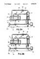
- FIG. 4Ais an enlarged view of the metered aperture area of FIGS. 2A-2C, and FIG. 4B is a further enlarged side view of the aperture;
- FIG. 5is a plan view of a modification of the embodiment shown in FIG. 1;
- FIG. 6is a front elevational view of the system shown in FIG. 5;
- FIGS. 7A and 7Bare enlarged side views of the apertures shown in FIGS. 2A-2C and 4A-4B.
- FIG. 1shows an analytical instrument having multiple analyzing sub-stations 10 and 100, each being capable of performing particle analysis on a liquid sample.
- FIGS. 2A-2Care front views of the sub-station 10. Since the sub-stations are essentially the same, their operation will be described with reference only to sub-station 10 as shown in FIGS. 2A-2C.
- Each sub-station represented by station 10includes a platform 11 for holding a sample container 13 which is divided into two reservoirs 15 and 16 by dividing wall 14.
- Reservoir 15holds a biological or industrial liquid suspension of particles to be analyzed and reservoir 16 holds a reagent 18.
- the liquid sample 17may be treated by the operator or other personnel before being added to reservoir 15.
- a series of conduit members 5A-5Dprovide intimate liquid contact between reservoirs 15 and 16 and a piston pump 21.
- Member 5Dprovides liquid contact between sample reservoir 15 and pump 21.
- Check valve 23is disposed between tube members 5A and 5B to permit liquid flow from the pump 21 to reservoir 16 while restricting flow in the opposite direction.
- Tube member 5Cinterconnects liquid sample reservoir 15 and reagent reservoir 16 to effect liquid flow therebetween as will be described in greater detail hereinbelow. It is to be understood that the liquid path created by conduit members 5A and 5B is optional.
- the systemoperates in accordance with the concepts of the underlying invention without the liquid pathway formed by conduit members 5A and 5B and those skilled in the art will appreciate from the discussion below that they are included for the purpose of increasing the system flow capacity and thus the efficiency of the flow system.
- the ends of members 5B, 5C and 5Dare provided, respectively, with aperture members 5E, 5F and 5G, termed the waste, fill and count apertures in view of their functions within the liquid flow system.
- the liquid sampleis aspirated through the count aperture 5G which has a sensing mechanism associated with it for detecting and counting each passing cell.
- the waste aperture 5E and fill aperture 5Fare approximately 200 micrometers in diameter, while the diameter of count aperture 5G varies between 45 micrometers for counting red blood cells and 100 micrometers for white cell counting.
- the diameter of the count aperturecorresponds to the diameter of the cell type being counted, thus allowing only one cell to pass through the aperture at a time.
- the waste and fill aperturehave a tapered, conical shape as shown in FIG. 7A, while the count aperture is arcuately shaped as shown in FIG. 7B.
- liquidis aspirated through fill aperture 5F from the diluent reservoir as a result of the negative pressure produced by downward movement of the piston in pump 21, and supplied through member 5C and around joining wall 2 where it contacts the sample liquid and suspended particles aspirated through aperture 5G at a point 5H just above count aperture 5G, as shown in FIGS. 4A and 4B.
- the wall 2 adjoining members 5C and 5Dterminates at a point 3 which is a greater distance above the aperture opening 5G than a point 6 at which outer wall 7 of member 5C terminates.
- This structureresults in a dynamic operation whereby particles 7, which enter aperture 5G with a velocity V, are entrained by the liquid flowing in member 5C in an area of increased volume. As a result, particles 7 are less likely to collide with and become lodged against wall portion 8.
- aperture member 5GThe bottom surface of aperture member 5G is tapered and elbowed at its rear portion where a passageway 4 is formed.
- the passageway 4mates with a conduit member 5J and together they form a chamber through which air is forced.
- This forced airserves two purposes. First, when the aperture 5G is immersed in the liquid before the count portion of the analytical cycle, the air mixes the solution to create a uniform particle suspension in the reservoir. The mixing process is discontinued during the counting cycle. Second, when the aperture 5G is removed from the reservoir 15, drops that collect on the bottom surface of the aperture will be urged toward the passageway 4 by the inclined surface to a point where the forced air will blow them off the surface.
- the mechanical movement of the platform 11 and piston pump 21is coordinated by a novel cam system including a series of cams 30, 31 mounted on a common cam shaft 32.
- This systemis described in detail in a contemporaneously filed U.S. patent application.
- the rotation of the shaft 32causes the cams 30 and 31 to move the pump and platform at the proper time in the analytical cycle by virtue of the cam-followers and springs which, in tandem, act to translate the rotational motion of the cams to linear motion for displacement of the platform and pump.
- An encoder 33 and corresponding sensor 33Adetect the relative rotational position of the shaft 32 and relay this information to a controller 34 for interpretation. Based on the relative position information, the controller outputs a stop, start or reverse control signal to motor 35.
- this cam systemis novel, it is not essential to the present invention and those of ordinary skill in the art will appreciate that the description thereof is provided for completeness and also that any method of coordinating and operating the platform and pump could be used in conjunction with the principles disclosed herein.
- FIGS. 2A-2CBefore its first use, the liquid flow system shown in FIGS. 2A-2C is filled with air.
- an operatorwill initially prime the system with a liquid by using a container 13A similar to container 13 but without the dividing wall 14.
- the cam-systemlifts the platform to immerse the apertures 5E, 5F and 5G in the liquid in container 13A.
- the negative pressure created by downward movement of the piston in pump 21draws liquid into embers 5C and 5D through both the fill and count apertures.
- no liquidis drawn into members 5A and 5B because of the action of check valve 23.
- FIG. 3Aan operator will initially prime the system with a liquid by using a container 13A similar to container 13 but without the dividing wall 14.
- the cam-systemlifts the platform to immerse the apertures 5E, 5F and 5G in the liquid in container 13A.
- the negative pressure created by downward movement of the piston in pump 21draws liquid into embers 5C and 5D through both the fill and count apertures.
- the pump pistonis caused to move upward, thereby forcing liquid back to the container 13A through tube members 5C, and 5D and through members 5A and 5B through check valve 23.
- tube members 5A, 5B, 5C and 5Dare all filled with liquid.
- the systemis ready for liquid sample analysis.
- the container 13Ais replaced by a liquid sample container 13.
- the anti-siphon feature of the present inventioncan be seen. Since the openings are all maintained at the same level, the liquid remaining in the tube members does not drain through apertures 5E, 5F and 5G when the sample containers 13A and 13 are interchanged. The surface tension between the liquid and the side and bottom walls of the tube adjacent the aperture also contribute to this effect.
- the cam systeminitiates an analytical cycle of the instrument.
- the pistonmoves downward within the pump 21 to create a negative relative pressure within the tube members causing liquid from the liquid sample 17 to be drawn up through the count aperture 5G, as indicted by the arrows in FIG. 2A.
- the count aperture sizeis chosen as indicated above such that one blood cell can pass through it at a time.
- a voltage potential U applied between a resistive wire electrode 41 placed in member 5C and plate electrode 42 disposed in sample reservoir 15causes a current to flow through conducting liquid 17.
- Appropriate electronics 44detect the change in current that occurs when a cell passes through the orifice of the aperture member 5G. Each passing cell causes the electronically recorded cell count to increase.
- the rate at which the piston descendsis predetermined in accordance with the size of the aperture to establish a desired liquid flow rate through aperture 5G during the intake phase of the instrument cycle.
- liquid 18is drawn into conduit member 5C from the reagent reservoir 16 through fill aperture 5F.
- the reagent liquid 18 drawn into member 5C through fill aperture 5Ftravels along conduit member 5C to a point 5H behind count aperture 5G, where members 5C and 5D are in intimate liquid contact.
- Some blood cells which enter count aperture 5Gwill have a tendency to remain at the point 5H just behind the aperture, thus causing interruption of current flow and a false cell count.
- a bubble chamber 20is formed at the top of the pump cavity for capturing bubbles formed in the liquid flow system. These bubbles are most commonly caused by the build-up of gas particles produced in the electro-chemical reaction at the count aperture electrodes 41 and 42. These gaseous bubbles travel up through member 5D and are collected in the cycle is terminated and the action of the piston in pump 21 reversed, the liquid and bubbles collected in the piston cavity are caused to exit through the conduit members 5A and 5D, the system being designed so that the volume of liquid collected in the pump is greater than the combined volume of the three tube members. The collected bubbles and liquid are forced through check valve 23 and back into the reagent reservoir 16 through waste aperture 5E, while some of the liquid instead finds its way back into conduit 5C and exits through fill aperture 5F.
- the pressure at the count apertureis maintained at six inches of mercury during both phases of liquid flow and the cross-sectional area of the waste aperture 5E is designed to be equal to the sum of the cross-sectional areas of the fill and count apertures 5F and 5G.
- the fill, count and waste aperturestypically have diameters of 200, 45, and 205 micrometers in diameter, respectively.
- the diametersare typically 200, 100 and 224 micrometers, respectively.
- the platform 11is lowered as shown in FIG. 2C so that container 13 can be removed and replaced.
- the present systemis self-filling, being pumped by a cycle identical to that used for the analytical step.
- the systemavoids any possible inaccuracies or contamination that might otherwise be introduced by uncontrolled siphoning of liquid.
- FIGS. 5 and 6show another embodiment of the invention wherein additional liquids 51 and 52, contained in reservoirs 53 and 54 must be introduced into the liquid sample reservoir 15. These liquids may be additional liquid samples or other reagents and may be added during or before the actual counting step.
- Conduit members 51A and 51Bprovide liquid contact between additional piston pump 55 and reservoir 53 through valve 56, while members 52A and 52B define a liquid path from reservoir 54 to piston pump 57 through valve 58.
- Conduit members 51C and 52Cdefine, respectively, liquid paths from the pumps 55 and 57 to the liquid sample reservoir 15 through valves 59 and 60.
- valve 59would be closed and valve 56 opened.
- the piston pump 55would then aspirate liquid 51 from the reservoir 53 up along member 51A, through valve 56 and into the piston cavity of pump 55 as shown in FIG. 6.
- valve 56would be closed and valve 59 opened.
- the action of piston pump 55would then be reversed to pump liquid into reservoir 15 through member 51C. This portion of the cycle is shown in FIG. 6 by the combination of valves 58 and 60 with pump 57.
- conduit members 51C and 52C in reservoir 15Cshould be kept at the same level as the open input ends of members 51A and 52A, respectively, and after completion of the count cycle, valves 56, 58, 59 and 60 should be maintained in the open position.
- the operation of the additional analyzing sub-stationsis essentially the same as described hereinabove, with the exception of some system timing concerns.
- the camsare designed so that the piston pump in each sub-station will sequentially effect the counting phase of the cycle before any discharge of liquid, i.e., the pump in station 10 will aspirate liquid through its count aperture to effect a cell count and then the pump in station 100 will draw liquid through its corresponding count aperture before the pump in station 10 begins to output the liquid drawn into its cavity.
- the pumpsare forced by the cam system to simultaneously initiate the output phase.
- Another advantage to this arrangementis that the system only requires one set of counting electronics with a counting signal input switchable between each sub-station of the measurement cycle, since noise created by the operation of the motor is not a concern during the flush portion of the analysis.
Landscapes
- Chemical & Material Sciences (AREA)
- Dispersion Chemistry (AREA)
- Physics & Mathematics (AREA)
- Health & Medical Sciences (AREA)
- Life Sciences & Earth Sciences (AREA)
- Analytical Chemistry (AREA)
- Biochemistry (AREA)
- General Health & Medical Sciences (AREA)
- General Physics & Mathematics (AREA)
- Immunology (AREA)
- Pathology (AREA)
- Automatic Analysis And Handling Materials Therefor (AREA)
- Investigating Or Analysing Biological Materials (AREA)
- Sampling And Sample Adjustment (AREA)
Abstract
Description
Claims (26)
Priority Applications (7)
| Application Number | Priority Date | Filing Date | Title |
|---|---|---|---|
| US07/347,522US5094818A (en) | 1989-05-04 | 1989-05-04 | Self-filling anti-siphon flow system for particle analysis |
| CA002015983ACA2015983A1 (en) | 1989-05-04 | 1990-05-03 | Self-filling anti-siphon fluid flow system for particle analysis methods and instruments |
| ES90304879TES2079439T3 (en) | 1989-05-04 | 1990-05-04 | ANTISIPHON AUTOMATIC FILLING FLUID CIRCULATION SYSTEM FOR PARTICULATE ANALYSIS METHODS AND INSTRUMENTS. |
| DE69022782TDE69022782T2 (en) | 1989-05-04 | 1990-05-04 | Self-filling anti-siphon, liquid flow system for methods and devices for particle analysis. |
| AT90304879TATE128769T1 (en) | 1989-05-04 | 1990-05-04 | SELF-FILLING ANTI-SIPHON, LIQUID FLOW SYSTEM FOR PARTICLE ANALYSIS METHODS AND APPARATUS. |
| EP90304879AEP0405729B1 (en) | 1989-05-04 | 1990-05-04 | Self-filling anti-siphon fluid flow system for particle analysis methods and instruments |
| JP2117271AJPH03102243A (en) | 1989-05-04 | 1990-05-07 | Instrument for analysis and methods of analyzing fluid flow and particle using the same |
Applications Claiming Priority (1)
| Application Number | Priority Date | Filing Date | Title |
|---|---|---|---|
| US07/347,522US5094818A (en) | 1989-05-04 | 1989-05-04 | Self-filling anti-siphon flow system for particle analysis |
Publications (1)
| Publication Number | Publication Date |
|---|---|
| US5094818Atrue US5094818A (en) | 1992-03-10 |
Family
ID=23364061
Family Applications (1)
| Application Number | Title | Priority Date | Filing Date |
|---|---|---|---|
| US07/347,522Expired - Fee RelatedUS5094818A (en) | 1989-05-04 | 1989-05-04 | Self-filling anti-siphon flow system for particle analysis |
Country Status (7)
| Country | Link |
|---|---|
| US (1) | US5094818A (en) |
| EP (1) | EP0405729B1 (en) |
| JP (1) | JPH03102243A (en) |
| AT (1) | ATE128769T1 (en) |
| CA (1) | CA2015983A1 (en) |
| DE (1) | DE69022782T2 (en) |
| ES (1) | ES2079439T3 (en) |
Cited By (5)
| Publication number | Priority date | Publication date | Assignee | Title |
|---|---|---|---|---|
| US5232666A (en)* | 1989-05-04 | 1993-08-03 | Abbott Laboratories | Cam-driven flow system for use with analytical instruments |
| US5287733A (en)* | 1990-09-23 | 1994-02-22 | Horiba Ltd. | Apparatus for receiving liquid treatment samples for disposal |
| US5402062A (en)* | 1993-12-23 | 1995-03-28 | Abbott Laboratories | Mechanical capture of count wafer for particle analysis |
| WO1995017658A1 (en)* | 1993-12-20 | 1995-06-29 | Abbott Laboratories | Mechanical capture of count wafer for particle analysis |
| EP4018175A4 (en)* | 2019-08-22 | 2022-10-05 | Iannotti, Michael | HIGH THROUGHPUT ANALYSIS AND SORTING AND SAMPLING INTERFACE AND HIGH THROUGHPUT ANALYSIS AND SORTING ARRANGEMENT |
Families Citing this family (2)
| Publication number | Priority date | Publication date | Assignee | Title |
|---|---|---|---|---|
| ES2071546B1 (en)* | 1992-11-02 | 1996-02-01 | Univ Granada | AUTOMATIC EXTRACTOR AND EXTRACTOR PROCEDURE, FOR SUSPENSION CLAY, FOR QUICK SAMPLING. |
| CN111742209B (en)* | 2018-12-21 | 2024-09-06 | 索尼公司 | Particle confirmation method, particle capture chip, and particle analysis system |
Citations (16)
| Publication number | Priority date | Publication date | Assignee | Title |
|---|---|---|---|---|
| US3299354A (en)* | 1962-07-05 | 1967-01-17 | Coulter Electronics | Aperture tube structure for particle study apparatus |
| US3444463A (en)* | 1965-11-26 | 1969-05-13 | Coulter Electronics | Particle analyzing apparatus and method utilizing multiple apertures |
| US3648158A (en)* | 1970-06-01 | 1972-03-07 | Contraves Ag | Conductivity cell for particle counting system |
| US3746976A (en)* | 1971-04-07 | 1973-07-17 | Coulter Electronics | Self-cleaning aperture tube for coulter study apparatus |
| US3781675A (en)* | 1972-04-27 | 1973-12-25 | Gen Science Corp | Self priming conductivity cell |
| US3793587A (en)* | 1971-03-10 | 1974-02-19 | Licentia Gmbh | Particle volume and cross-section measurement |
| US3854088A (en)* | 1972-11-30 | 1974-12-10 | Contraves Ag | Counting and analysis apparatus for particles suspended in an electrolytic liquid |
| US3902115A (en)* | 1973-09-26 | 1975-08-26 | Coulter Electronics | Self-cleaning aperture tube for coulter study apparatus and electrolyte supply system therefor |
| US3924180A (en)* | 1973-10-12 | 1975-12-02 | Us Energy | Potential sensing cell analyzer |
| US3930736A (en)* | 1974-07-01 | 1976-01-06 | Coulter Electronics, Inc. | Aperture tube with attached thief |
| US4157499A (en)* | 1977-09-15 | 1979-06-05 | Becton, Dickinson And Company | Blood cell counter having dual testing heads |
| US4564803A (en)* | 1983-08-29 | 1986-01-14 | Coulter Corporation | Method and apparatus for removing foreign matter from a flow cell of a particle study device |
| US4631483A (en)* | 1984-02-01 | 1986-12-23 | Coulter Electronics, Inc. | Particle analyzing apparatus and method of moving particles in suspension through such apparatus |
| US4653078A (en)* | 1984-04-09 | 1987-03-24 | Hitachi, Ltd. | Method and apparatus for detecting occurrence of clogging conditions by counting particles suspended in a liquid method |
| US4710021A (en)* | 1983-10-14 | 1987-12-01 | Sequoia-Turner Corporation | Particulate matter analyzing apparatus and method |
| US4767600A (en)* | 1984-06-19 | 1988-08-30 | Finbiomedica S.R.L. | Equipment for rapid, automatic chemical-clinical analysis |
Family Cites Families (2)
| Publication number | Priority date | Publication date | Assignee | Title |
|---|---|---|---|---|
| GB916238A (en)* | 1969-02-05 | 1963-01-23 | Technicon Instr | Apparatus for supplying sample liquids and reagents for analysis and other purposes |
| US4528158A (en)* | 1982-06-14 | 1985-07-09 | Baird Corporation | Automatic sampling system |
- 1989
- 1989-05-04USUS07/347,522patent/US5094818A/ennot_activeExpired - Fee Related
- 1990
- 1990-05-03CACA002015983Apatent/CA2015983A1/ennot_activeAbandoned
- 1990-05-04ESES90304879Tpatent/ES2079439T3/ennot_activeExpired - Lifetime
- 1990-05-04DEDE69022782Tpatent/DE69022782T2/ennot_activeExpired - Fee Related
- 1990-05-04ATAT90304879Tpatent/ATE128769T1/ennot_activeIP Right Cessation
- 1990-05-04EPEP90304879Apatent/EP0405729B1/ennot_activeExpired - Lifetime
- 1990-05-07JPJP2117271Apatent/JPH03102243A/enactivePending
Patent Citations (16)
| Publication number | Priority date | Publication date | Assignee | Title |
|---|---|---|---|---|
| US3299354A (en)* | 1962-07-05 | 1967-01-17 | Coulter Electronics | Aperture tube structure for particle study apparatus |
| US3444463A (en)* | 1965-11-26 | 1969-05-13 | Coulter Electronics | Particle analyzing apparatus and method utilizing multiple apertures |
| US3648158A (en)* | 1970-06-01 | 1972-03-07 | Contraves Ag | Conductivity cell for particle counting system |
| US3793587A (en)* | 1971-03-10 | 1974-02-19 | Licentia Gmbh | Particle volume and cross-section measurement |
| US3746976A (en)* | 1971-04-07 | 1973-07-17 | Coulter Electronics | Self-cleaning aperture tube for coulter study apparatus |
| US3781675A (en)* | 1972-04-27 | 1973-12-25 | Gen Science Corp | Self priming conductivity cell |
| US3854088A (en)* | 1972-11-30 | 1974-12-10 | Contraves Ag | Counting and analysis apparatus for particles suspended in an electrolytic liquid |
| US3902115A (en)* | 1973-09-26 | 1975-08-26 | Coulter Electronics | Self-cleaning aperture tube for coulter study apparatus and electrolyte supply system therefor |
| US3924180A (en)* | 1973-10-12 | 1975-12-02 | Us Energy | Potential sensing cell analyzer |
| US3930736A (en)* | 1974-07-01 | 1976-01-06 | Coulter Electronics, Inc. | Aperture tube with attached thief |
| US4157499A (en)* | 1977-09-15 | 1979-06-05 | Becton, Dickinson And Company | Blood cell counter having dual testing heads |
| US4564803A (en)* | 1983-08-29 | 1986-01-14 | Coulter Corporation | Method and apparatus for removing foreign matter from a flow cell of a particle study device |
| US4710021A (en)* | 1983-10-14 | 1987-12-01 | Sequoia-Turner Corporation | Particulate matter analyzing apparatus and method |
| US4631483A (en)* | 1984-02-01 | 1986-12-23 | Coulter Electronics, Inc. | Particle analyzing apparatus and method of moving particles in suspension through such apparatus |
| US4653078A (en)* | 1984-04-09 | 1987-03-24 | Hitachi, Ltd. | Method and apparatus for detecting occurrence of clogging conditions by counting particles suspended in a liquid method |
| US4767600A (en)* | 1984-06-19 | 1988-08-30 | Finbiomedica S.R.L. | Equipment for rapid, automatic chemical-clinical analysis |
Cited By (7)
| Publication number | Priority date | Publication date | Assignee | Title |
|---|---|---|---|---|
| US5232666A (en)* | 1989-05-04 | 1993-08-03 | Abbott Laboratories | Cam-driven flow system for use with analytical instruments |
| US5287733A (en)* | 1990-09-23 | 1994-02-22 | Horiba Ltd. | Apparatus for receiving liquid treatment samples for disposal |
| WO1995017658A1 (en)* | 1993-12-20 | 1995-06-29 | Abbott Laboratories | Mechanical capture of count wafer for particle analysis |
| US5501982A (en)* | 1993-12-20 | 1996-03-26 | Abbott Laboratories | Method of using a disposable reagent pack |
| US5402062A (en)* | 1993-12-23 | 1995-03-28 | Abbott Laboratories | Mechanical capture of count wafer for particle analysis |
| EP4018175A4 (en)* | 2019-08-22 | 2022-10-05 | Iannotti, Michael | HIGH THROUGHPUT ANALYSIS AND SORTING AND SAMPLING INTERFACE AND HIGH THROUGHPUT ANALYSIS AND SORTING ARRANGEMENT |
| US11604195B2 (en) | 2019-08-22 | 2023-03-14 | Michael IANNOTTI | High throughput analysis and sorting, and sampling interface and assembly for high throughput analysis and sorting |
Also Published As
| Publication number | Publication date |
|---|---|
| ATE128769T1 (en) | 1995-10-15 |
| JPH03102243A (en) | 1991-04-26 |
| DE69022782D1 (en) | 1995-11-09 |
| DE69022782T2 (en) | 1996-03-14 |
| EP0405729A3 (en) | 1991-11-21 |
| CA2015983A1 (en) | 1990-11-04 |
| EP0405729B1 (en) | 1995-10-04 |
| EP0405729A2 (en) | 1991-01-02 |
| ES2079439T3 (en) | 1996-01-16 |
Similar Documents
| Publication | Publication Date | Title |
|---|---|---|
| US5380491A (en) | Apparatus for pumping and directing fluids for hematology testing | |
| EP0360487B1 (en) | Method and apparatus for analysis of particles contained in a liquid sample | |
| JP2972367B2 (en) | Cell analyzer | |
| JP5096170B2 (en) | Dual sample cartridge and method for characterizing particles in a liquid | |
| CN102998474B (en) | Method for employing apparatus for aspirating and dispensing liquids in automated analyzer | |
| US4683212A (en) | Random access single channel sheath stream apparatus | |
| US5728351A (en) | Apparatus for making a plurality of reagent mixtures and analyzing particle distributions of the reagent mixtures | |
| US20180172717A1 (en) | Analysis apparatus | |
| US20080202217A1 (en) | Dual Sample Cartridge and Method for Characterizing Particles in Liquid | |
| US5905214A (en) | Particle detector and particle analyzing apparatus | |
| EP0515658A1 (en) | Aspiration method for hematology analyzing apparatus | |
| US5094818A (en) | Self-filling anti-siphon flow system for particle analysis | |
| US6812032B1 (en) | Apparatus and method for making a plurality of reagent mixtures and analyzing particle distributions of the reagent mixtures | |
| US4264327A (en) | Method and apparatus for automatic competitive binding analysis | |
| US4002269A (en) | Liquid proportioning system in a liquid sample analyzer | |
| US6555065B1 (en) | Automatic hematologic counting and analysing device | |
| JPS6140541A (en) | Measuring device for predetermined characteristic of suspended particle in carrying medium | |
| JPH05119036A (en) | Particle measuring device | |
| JPH04369461A (en) | Particle measuring apparatus | |
| EP0789843B1 (en) | Apparatus for pumping and directing fluids for hematology testing | |
| CA2199256A1 (en) | Apparatus for pumping and directing fluids for hematology testing | |
| JPH0756491B2 (en) | Anti-pollution container and analyzer using the same | |
| JPH0752191B2 (en) | Analysis device and analysis method |
Legal Events
| Date | Code | Title | Description |
|---|---|---|---|
| AS | Assignment | Owner name:BIOGENIX CORPORTION, FLORIDA Free format text:ASSIGNMENT OF ASSIGNORS INTEREST.;ASSIGNORS:LONGMAN, MILLARD;PRONI, OSCAR;BURDMAN, RICHARD A.;REEL/FRAME:005842/0566 Effective date:19890414 | |
| AS | Assignment | Owner name:BIOGENIX CORPORATION, FLORIDA Free format text:ASSIGNMENT OF ASSIGNORS INTEREST.;ASSIGNORS:LONGMAN, MILLARD;PRONI, OSCAR;BURDMAN, RICHARD A.;REEL/FRAME:005426/0013 Effective date:19890414 | |
| AS | Assignment | Owner name:EXACT SCIENCE, INC. Free format text:CHANGE OF NAME;ASSIGNOR:BIOGENIX CORPORATION;REEL/FRAME:005909/0811 Effective date:19890629 | |
| FEPP | Fee payment procedure | Free format text:ENTITY STATUS SET TO UNDISCOUNTED (ORIGINAL EVENT CODE: BIG.); ENTITY STATUS OF PATENT OWNER: LARGE ENTITY | |
| CC | Certificate of correction | ||
| AS | Assignment | Owner name:ABBOTT LABORATORIES Free format text:ASSIGNMENT OF ASSIGNORS INTEREST;ASSIGNOR:EXACT SCIENCE INC.;REEL/FRAME:007408/0427 Effective date:19950327 | |
| FPAY | Fee payment | Year of fee payment:4 | |
| REMI | Maintenance fee reminder mailed | ||
| LAPS | Lapse for failure to pay maintenance fees | ||
| FP | Lapsed due to failure to pay maintenance fee | Effective date:20000310 | |
| STCH | Information on status: patent discontinuation | Free format text:PATENT EXPIRED DUE TO NONPAYMENT OF MAINTENANCE FEES UNDER 37 CFR 1.362 |