US5094301A - Programmable pulsed torque recovery system - Google Patents
Programmable pulsed torque recovery systemDownload PDFInfo
- Publication number
- US5094301A US5094301AUS07/489,177US48917790AUS5094301AUS 5094301 AUS5094301 AUS 5094301AUS 48917790 AUS48917790 AUS 48917790AUS 5094301 AUS5094301 AUS 5094301A
- Authority
- US
- United States
- Prior art keywords
- torque
- nutrunner
- motor
- joint
- pulse
- Prior art date
- Legal status (The legal status is an assumption and is not a legal conclusion. Google has not performed a legal analysis and makes no representation as to the accuracy of the status listed.)
- Expired - Lifetime
Links
Images


Classifications
- B—PERFORMING OPERATIONS; TRANSPORTING
- B25—HAND TOOLS; PORTABLE POWER-DRIVEN TOOLS; MANIPULATORS
- B25B—TOOLS OR BENCH DEVICES NOT OTHERWISE PROVIDED FOR, FOR FASTENING, CONNECTING, DISENGAGING OR HOLDING
- B25B23/00—Details of, or accessories for, spanners, wrenches, screwdrivers
- B25B23/14—Arrangement of torque limiters or torque indicators in wrenches or screwdrivers
- B25B23/147—Arrangement of torque limiters or torque indicators in wrenches or screwdrivers specially adapted for electrically operated wrenches or screwdrivers
- B25B23/1475—Arrangement of torque limiters or torque indicators in wrenches or screwdrivers specially adapted for electrically operated wrenches or screwdrivers for impact wrenches or screwdrivers
- B—PERFORMING OPERATIONS; TRANSPORTING
- B25—HAND TOOLS; PORTABLE POWER-DRIVEN TOOLS; MANIPULATORS
- B25B—TOOLS OR BENCH DEVICES NOT OTHERWISE PROVIDED FOR, FOR FASTENING, CONNECTING, DISENGAGING OR HOLDING
- B25B23/00—Details of, or accessories for, spanners, wrenches, screwdrivers
- B25B23/14—Arrangement of torque limiters or torque indicators in wrenches or screwdrivers
- B25B23/147—Arrangement of torque limiters or torque indicators in wrenches or screwdrivers specially adapted for electrically operated wrenches or screwdrivers
Definitions
- This inventionrelates to a system and process for tightening threaded fasteners to a final predetermined condition and, more particularly, it concerns such a system and process which compensates for joint relaxation.
- a joint or joint assemblyis made up of two or more work pieces joined together by one or more threaded fasteners, such as a nut and a threaded stud, a nut and a bolt, or a bolt and a threaded opening in one of the joint pieces.
- threaded fastenerssuch as a nut and a threaded stud, a nut and a bolt, or a bolt and a threaded opening in one of the joint pieces.
- Modern production facilitiesutilize single or multiple pneumatic or electric nutrunning tools (spindles) to rundown threaded fasteners and, thereby, assemble joints.
- Conventional nutrunning tool control systems or methodssuch as torque control or stall, turn-of-the-nut, yield point, and two stage (two speed), use torque and angle sensors associated with the nutrunners to control nutrunner operation to set each fastener at a predetermined final or target torque. Examples of such conventional fastening systems and techniques are disclosed in U.S. Pat. Nos. Re 31,569 issued to S. Eshghy on May 1, 1984, 3,965,778 issued to A. J. Aspers et al on June 29, 1976, and 4,016,938 issued to E. E. Rice on Apr. 12, 1977.
- Joint relaxation due to, for example, metal flow, gasket compression, or gasket flowreduces the joint clamp load and torque retention of the fasteners. Joint relaxation following a fastener tightening operation results in a true final torque and clamp load on the fastener which is less than the desired fastener torque and clamp load. Torque and load loss due to joint relaxation is especially troublesome in soft or gasketed joints.
- Pulse driven pneumatic nutrunners and impact wrenchesare known in the joint fastening art. Examples of such pneumatic tools are described in U.S. Pat. Nos. 2,569,244 issued to G. B. Larson on Sept. 25, 1951, 4,019,589 issued to W. K. Wallace on Apr. 26, 1977, 4,084,487 issued to W. K. Wallace on Apr. 18, 1978, 4,121,670 issued to G. A. Antipov et al on Oct. 24, 1978, and 4,544,039 issued to D. O. Crane on Oct. 1, 1985. Pneumatic pulse or impact wrenches tend to suffer from undesirable motor and gear wear because the motor and gearing relax between drive pulses.
- a system and method for tightening threaded fastener assemblies or jointsis provided by which joint relaxation is compensated for by oscillating the drive torque of a tightening tool at the end of a tightening cycle and in a manner which causes the threaded fastener to rotate if the joint relaxes while not allowing the tightening tool motor and gearing to relax between pulses so as to avoid undue machine wear.
- the present inventionis directed to a programmable electric nutrunner fastening system and technique for recovering torque loss due to joint relaxation.
- an analog nutrunner motor drive signalis oscillated or pulsed at the end of a tightening cycle at a programmed frequency and amplitude based on the particular joint application.
- the present inventioncompensates or corrects for joint relaxation in threaded fastener assemblies or bolted joints and, thereby, ensures the highest or optimum clamp load and torque retention.
- the present inventionis especially, although not exclusively, adapted for use with gasketed joints and other medium-to-soft joints.
- a principle object of the present inventionis the provision of a pulsed torque recovery method and apparatus which corrects for joint relaxation. Another and more specific object of the present invention is to provide a programmable system and method which is readily adaptable to a variety of joint materials and applications. Yet another object of the present invention is the provision of a pulsed torque system and process by which the static to dynamic torque condition of the joint is overcome. Yet still another object of the present invention is provided by an embodiment which allows for the selection of a pulse minimum amplitude which ensures that the nutrunner motor and gearing remain under load. A further object of the present invention is the provision of a pulsed torque recovery system which utilizes a ramped torque increase to reduce drive tool gear wear.
- FIG. 1is a schematic diagram illustrating an exemplary electric nutrunner system in accordance with the present invention
- FIG. 2is an exemplary torque/time plot made using the programmable pulse torque recovery system of the present invention
- FIG. 3is an exemplary torque/angle plot made using the programmable pulse torque recovery system of the present invention.
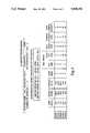
- FIG. 4is a schematic representation of an exemplary DC Motor Programming Cycle Steps and Full-Scales screen associated with the present system.
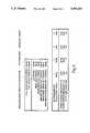
- FIG. 5is a schematic illustration of an exemplary DC Motor Programming Program Jogs, Backouts, and Pulse Torque Recovery Setpoints screen in accordance with an embodiment of the present invention.
- an exemplary electric nutrunner system in accordance with the present inventionis generally designated by the reference numeral 10 and shown to include as components an AC/DC converter 12, quality monitoring and control electronics 14, a Programmable Logic Controller (PLC) 16, a DC-motor servo controller 18, and one or more motors or nutrunners 20.
- Each of the motors 20includes a resolver 22, a brushless motor 24, a gear set 26, a transducer 28, and a spindle 30. It is preferred that the motors 20 are EMT Series brushless DC motors from ITD Automation of Troy, Mich.
- the quality monitoring and control electronics 14includes an industrialized IBM-PC, floppy and hard disk memory units, spindle modules, a keyboard, and a CRT display.
- the PLC 16 functionis provided by the control electronics 14.
- the servo controller 18is made up of one or more ITD Automation modular Servo Amplifier Systems each of which includes a power supply module and as many as five servo amplifier modules with matching individual spindle backplane modules.
- a preferred electric nutrunner system for the practice of the present inventionis the DL3 Fastening System by ITD Automation of Troy, Mich.
- power to the nutrunner 20is controlled by the DC-motor servo controller 18 based on motor control and angle signals from the resolver 22 mounted on the brushless motor 24.
- Torque signals from the transducer 28 and angle of rotation signals developed by the servo controller 18are monitored by, for example, spindle modules, in the control electronics 14.
- Control signals from, for example, spindle modules in the control electronics 14are sent to the servo controller 18 to shut off the motor 20 when torque and angle targets are achieved.
- Motor speed and torque reference signalsare provided to the servo controller 18 by the PLC 16.
- the control electronics 14are programmed in a manner that allows a system user to not only select a pulsed torque recovery (PTR) period at the end of a tightening cycle (FIGS. 2 and 3), but also makes provision for the system user to program particular pulse maximum and minimum torque values and pulse torque duration (FIG. 5) as will be described in greater detail below.
- FIGS. 2 and 3 of the drawingsrelate to one another in that they depict the same exemplary tightening cycle including pulsed torque recovery (PTR).
- FIGS. 2 and 3differ in that FIG. 2 relates torque to elapsed time, while FIG. 3 relates torque to angle of rotation.
- FIGS. 2 and 3 of the drawingsshow the torque/time and angle/time plots as part of one of the user friendly display screens of the above-mentioned DL3 Fastening System by ITD Automation.
- an exemplary tightening cycle plot 32has a target torque of 100 Newton-meters of torque (Nt-m) and a pulsed torque recovery frequency of about 100 Hz.
- the pulsed torque (PTR) at the end of the tightening cycleis shown to occur from about 1508 milliseconds to about 2137 milliseconds.
- the pulsed torque amplituderanged from a maximum of about 100 Nt-m to a minimum of about 80 Nt-m.
- the pulsed torque recovery (PTR) section of a tightening cycle plot 34accounts for about a 5 degree increase in the angle of rotation of the threaded fastener from approximately 58 degrees to about 63 degrees.
- the programmable pulsed torque recovery feature of the present inventionprovided about a 5 degree rotation of the threaded fastener without raising the torque above the target or final torque of about 100 Nt-m.
- the torqueis pulsed after all 10 fasteners have been run down to the target torque.
- the torqueis pulsed between 80 and 100% of the target torque so that a positive torque is maintained as the gasket material condenses and flows.
- the pulsed torque technique of the present inventionprovides for a realization of torque recovery not possible with a conventional simple stall tightening process.
- the pulsation of the torque at the end of the tightening cycle in accordance with the present inventionovercomes the static to dynamic torque condition of the joint. Typically, a greater torque is required to start a fastener to more than to keep it moving under a loaded condition.
- the pulsed torque recovery of the present inventionis programmable and, as such, provides for compatibility with soft, medium or even hard joints. For example, if a specific application has a very high static to dynamic torque ratio, the torque pulsation is programmed such that a high pulsed torque maximum amplitude value which is above the target torque will compensate for the condition. Conversely, if the application is extremely soft, such as a joint including a rubber bushing, the maximum amplitude value of the pulsed torque is set below the final torque.
- Another advantage of the present inventionis realized by programming the minimum pulsation torque value high enough to keep the nutrunner gear set and motor under load, thereby, assuring maximum gear and motor durability. Previous attempts at joint tightening using pneumatic systems which go from a no-load to a loaded condition have experienced considerable undesirable wear and degradation due to excessive impacting on the pneumatic motors and gear drive.
- the frequency of torque pulsationsis programmable in the system hardware.
- approximately 100 Hzis an optimum frequency with a range of from about 50 to 300 Hz being realistic for the mechanics of threaded fastening.
- FIGS. 4 and 5 of the drawingsdepict exemplary user friendly DC motor programming screens which facilitate the programming of cycle steps and full scales (FIG. 4) and program jogs, backouts, and pulsed-torque-recovery speeds and torques (FIG. 5).
- the cycle steps and full scale screenmakes provision for the entrance of values for motor full scale torque and speed, and several sequential steps each with speed, torque and time set points.
- This datawhen written to memory, is available to the motor controller program operating in the nutrunner system. These values become set points to the PLC function of the fastening system and are automatically scaled to 12 bits by the program editor. Depending on full scale and the value entered, the value may be slightly rounded off since the analog system hardware has a resolution of one part in four thousand ninety-six.
- the speed and torque reference signals transmitted to the servo amplifiers in the present system 10are 0 to 10 volts. As such, when entering the full scale values, the maximum motor speed and torque values are entered at 10 volts (at the tool).
- the DC nutrunner systemhas the capability of sequential rundowns.
- up to five stepscan be programmed with the set points of time (sec), speed (rpm), torque (e.u.), forward or reverse (fwd) or (rev), limit set number, cycle on (y/n), synchronization required (y/n), expedite on synchronization (y/n), and synchronization method (t/d/s/n).
- the time set pointallows up to 3200 seconds to be assigned to each step of motor operation.
- the speed set pointaffords the system user the opportunity to select the nutrunner speed in rpm's in each of the steps.
- the torque set pointprovides for the entrance in engineering units of the torque desired to run the nutrunner to in each of the steps.
- the forward and reverse set pointallows the user to select whether the motor should run in forward or reverse in each of the steps.
- the limit set pointis the applicable spindle module limit set number associated with the cycle step. Complex operations such as pre-torque, backout, and fasten may use multiple limit sets to perform the operation correctly.
- the cycle on set pointindicates whether or not the user wants the cycle on signal transmitted to the spindle module for each of the steps. Typically, on a reverse or backout operation, the spindle modules are not in cycle.
- the synchronation required set pointis used to indicate whether or not the entire station must synchronize at this step.
- the cycleis terminated. If synchronation is required (y), and the station does not successfully synchronize, the cycle is terminated. If synchronization is not required (n), the cycle will continue regardless of the synchronization succeeding or failing.
- the expedite on synchronization set pointallows the user to indicate whether or not the process can exit the existing step early if station synchronization is achieved.
- the sync method set pointprovides the following four options for synchronization: torque achieved (t) signaled directly from the servo amp; done (d) signalled from the spindle module indicating the algorithm is complete; sync (s) signal from the spindle module indicating that control reference torque is achieved; or none (n).
- the program jogs, backouts, and pulse torque recovery screenis used to facilitate programming the jog speed and torque, the manual backout speeds and torques, and to program the pulse torque recovery set points.
- the torqueis pulsed following the last programmed cycle step.
- the pulsing high, low and duration set pointsare programmable items.
- the duty cycleis hard set within the PLC program.
- the followingis an exemplary ladder logic program listing of an exemplary DC motor program.
- the pulsed torque recovery of the present inventionis accomplished within the ladder logic.
- the two sets of instructions that have the recurring beginning 123 and ending 384 instruction numberseffectively represent the oscillation between minimum and maximum torque value which is controlled by an overall program timer.
- the frequency of the oscillationis set at approximately 100 Hz, while it can be programmed in hardware (Eproms) between 50 and 300 Hz.
Landscapes
- Engineering & Computer Science (AREA)
- Mechanical Engineering (AREA)
- Details Of Spanners, Wrenches, And Screw Drivers And Accessories (AREA)
Abstract
Description
Claims (10)
Priority Applications (2)
| Application Number | Priority Date | Filing Date | Title |
|---|---|---|---|
| US07/489,177US5094301A (en) | 1990-01-05 | 1990-03-05 | Programmable pulsed torque recovery system |
| DE4100157ADE4100157A1 (en) | 1990-01-05 | 1991-01-04 | PROGRAMMABLE IMPULSE TORQUE RECOVERY DEVICE |
Applications Claiming Priority (2)
| Application Number | Priority Date | Filing Date | Title |
|---|---|---|---|
| US46161190A | 1990-01-05 | 1990-01-05 | |
| US07/489,177US5094301A (en) | 1990-01-05 | 1990-03-05 | Programmable pulsed torque recovery system |
Related Parent Applications (1)
| Application Number | Title | Priority Date | Filing Date |
|---|---|---|---|
| US46161190AContinuation-In-Part | 1990-01-05 | 1990-01-05 |
Publications (1)
| Publication Number | Publication Date |
|---|---|
| US5094301Atrue US5094301A (en) | 1992-03-10 |
Family
ID=27040065
Family Applications (1)
| Application Number | Title | Priority Date | Filing Date |
|---|---|---|---|
| US07/489,177Expired - LifetimeUS5094301A (en) | 1990-01-05 | 1990-03-05 | Programmable pulsed torque recovery system |
Country Status (2)
| Country | Link |
|---|---|
| US (1) | US5094301A (en) |
| DE (1) | DE4100157A1 (en) |
Cited By (17)
| Publication number | Priority date | Publication date | Assignee | Title |
|---|---|---|---|---|
| US5343785A (en)* | 1991-10-23 | 1994-09-06 | Emerson Electric Co. | Ultrasonic bolting control apparatus |
| US5519604A (en)* | 1993-09-02 | 1996-05-21 | Atlas Copco Tools Ab | Method and device for tightening threaded joints |
| US5845718A (en)* | 1997-05-29 | 1998-12-08 | Ingersoll-Rand Company | Resonant oscillating mass-based torquing tool |
| US5848655A (en)* | 1997-05-29 | 1998-12-15 | Ingersoll-Rand Company | Oscillating mass-based tool with dual stiffness spring |
| EP0911119A3 (en)* | 1997-10-27 | 2000-03-29 | Atlas Copco Tools Ab | Method for determining the installed torque in a screw joint at impulse tightening and a torque impulse tool for tightening a screw joint to a predetermined torque level |
| EP1008423A3 (en)* | 1998-12-10 | 2001-05-02 | Atlas Copco Tools Ab | Power tool system with programmable control unit. |
| US6536402B2 (en) | 2001-05-04 | 2003-03-25 | Caterpillar Inc. | Programmable torque limit |
| WO2004003695A3 (en)* | 2002-06-27 | 2004-06-24 | Snap On Tech Inc | Tool apparatus, system and method of use |
| US20040217727A1 (en)* | 1993-07-06 | 2004-11-04 | Gilmore Alan A | Electrical power tool having a motor control circuit for providing control over the torque output of the power tool |
| EP1151821A3 (en)* | 2000-05-03 | 2005-05-18 | Cooper Power Tools GmbH & Co. | Screw-driving system |
| US20050173142A1 (en)* | 2002-06-27 | 2005-08-11 | Cutler Brian J. | Tool apparatus, system and method of use |
| US20050207191A1 (en)* | 2004-03-22 | 2005-09-22 | Ulrich Kaminski | Routing of power and data from a voltage source to multiple electrically powered tools in a multi-tool processing station |
| US20050205275A1 (en)* | 2004-03-22 | 2005-09-22 | Ulrich Kaminski | Intelligent tightening spindle with integrated measurement transducer, servo amplifier, and data processing unit |
| US20100252288A1 (en)* | 2009-04-07 | 2010-10-07 | Hsu Chin-Ho | Pneumatic tool having a rotational speed detection device |
| US20100275747A1 (en)* | 2007-12-05 | 2010-11-04 | Atlas Copco Tools Ab | Power tool and a method for use of the power tool |
| JP2014054704A (en)* | 2012-09-13 | 2014-03-27 | Yutani:Kk | Fastening tool |
| US9126317B2 (en) | 2002-06-27 | 2015-09-08 | Snap-On Incorporated | Tool apparatus system and method of use |
Families Citing this family (3)
| Publication number | Priority date | Publication date | Assignee | Title |
|---|---|---|---|---|
| EP0734116B1 (en)* | 1995-03-24 | 2000-09-20 | Marquardt GmbH | Electrical motor control device and method |
| DE19617272B4 (en)* | 1995-05-12 | 2005-12-15 | Volkswagen Ag | Method and device for producing a screw connection |
| DE102005033323A1 (en)* | 2005-07-16 | 2007-01-18 | Bosch Rexroth Aktiengesellschaft | Tool, in particular screwing tool |
Citations (10)
| Publication number | Priority date | Publication date | Assignee | Title |
|---|---|---|---|---|
| US2569244A (en)* | 1945-04-20 | 1951-09-25 | Independent Pneumatic Tool Co | Portable power-driven tool |
| US3965778A (en)* | 1974-09-19 | 1976-06-29 | Standard Pressed Steel Co. | Multi-stage tightening system |
| US4016938A (en)* | 1975-12-02 | 1977-04-12 | Ingersoll-Rand Company | Method for fastener tensioning |
| US4019589A (en)* | 1975-12-02 | 1977-04-26 | Chicago Pneumatic Tool Company | Pulse motor nut runner |
| US4074772A (en)* | 1976-03-04 | 1978-02-21 | Thor Power Tool Company | Torquing tool control circuit |
| US4121670A (en)* | 1977-02-25 | 1978-10-24 | Vsesojuzny Nauchno-Issledova-Telsky I Proektno-Konstruktorsky Institut Mekhanizirovannogo I Ruchnogo Stroitelno-Montazhnogo Instrumenta, Vibratorov I Stroitelno-Otdelochnykh Mashin | Impact wrench |
| US4147219A (en)* | 1977-11-21 | 1979-04-03 | Chicago Pneumatic Tool Company | Two-speed offset nutrunner |
| USRE31569E (en)* | 1976-08-09 | 1984-05-01 | Rockwell International Corporation | Tension control of fasteners |
| US4544039A (en)* | 1983-04-01 | 1985-10-01 | Crane Electronics, Limited | Torque transducing systems for impact tools and impact tools incorporating such systems |
| US4908926A (en)* | 1987-12-23 | 1990-03-20 | Honda Giken Kogyo Kabushiki Kaisha | Method of and apparatus for controlling nut runner |
- 1990
- 1990-03-05USUS07/489,177patent/US5094301A/ennot_activeExpired - Lifetime
- 1991
- 1991-01-04DEDE4100157Apatent/DE4100157A1/ennot_activeCeased
Patent Citations (11)
| Publication number | Priority date | Publication date | Assignee | Title |
|---|---|---|---|---|
| US2569244A (en)* | 1945-04-20 | 1951-09-25 | Independent Pneumatic Tool Co | Portable power-driven tool |
| US3965778A (en)* | 1974-09-19 | 1976-06-29 | Standard Pressed Steel Co. | Multi-stage tightening system |
| US4016938A (en)* | 1975-12-02 | 1977-04-12 | Ingersoll-Rand Company | Method for fastener tensioning |
| US4019589A (en)* | 1975-12-02 | 1977-04-26 | Chicago Pneumatic Tool Company | Pulse motor nut runner |
| US4084487A (en)* | 1975-12-02 | 1978-04-18 | Chicago Pneumatic Tool Company | Pulse motor in a nut runner |
| US4074772A (en)* | 1976-03-04 | 1978-02-21 | Thor Power Tool Company | Torquing tool control circuit |
| USRE31569E (en)* | 1976-08-09 | 1984-05-01 | Rockwell International Corporation | Tension control of fasteners |
| US4121670A (en)* | 1977-02-25 | 1978-10-24 | Vsesojuzny Nauchno-Issledova-Telsky I Proektno-Konstruktorsky Institut Mekhanizirovannogo I Ruchnogo Stroitelno-Montazhnogo Instrumenta, Vibratorov I Stroitelno-Otdelochnykh Mashin | Impact wrench |
| US4147219A (en)* | 1977-11-21 | 1979-04-03 | Chicago Pneumatic Tool Company | Two-speed offset nutrunner |
| US4544039A (en)* | 1983-04-01 | 1985-10-01 | Crane Electronics, Limited | Torque transducing systems for impact tools and impact tools incorporating such systems |
| US4908926A (en)* | 1987-12-23 | 1990-03-20 | Honda Giken Kogyo Kabushiki Kaisha | Method of and apparatus for controlling nut runner |
Cited By (26)
| Publication number | Priority date | Publication date | Assignee | Title |
|---|---|---|---|---|
| US5343785A (en)* | 1991-10-23 | 1994-09-06 | Emerson Electric Co. | Ultrasonic bolting control apparatus |
| US20040217727A1 (en)* | 1993-07-06 | 2004-11-04 | Gilmore Alan A | Electrical power tool having a motor control circuit for providing control over the torque output of the power tool |
| US7112934B2 (en)* | 1993-07-06 | 2006-09-26 | Black & Decker Inc. | Electrical power tool having a motor control circuit for providing control over the torque output of the power tool |
| US5519604A (en)* | 1993-09-02 | 1996-05-21 | Atlas Copco Tools Ab | Method and device for tightening threaded joints |
| US5845718A (en)* | 1997-05-29 | 1998-12-08 | Ingersoll-Rand Company | Resonant oscillating mass-based torquing tool |
| US5848655A (en)* | 1997-05-29 | 1998-12-15 | Ingersoll-Rand Company | Oscillating mass-based tool with dual stiffness spring |
| EP0911119A3 (en)* | 1997-10-27 | 2000-03-29 | Atlas Copco Tools Ab | Method for determining the installed torque in a screw joint at impulse tightening and a torque impulse tool for tightening a screw joint to a predetermined torque level |
| US6390205B2 (en) | 1998-12-10 | 2002-05-21 | Atlas Copco Tools Ab | Power tool system with programmable control unit |
| EP1008423A3 (en)* | 1998-12-10 | 2001-05-02 | Atlas Copco Tools Ab | Power tool system with programmable control unit. |
| EP1151821A3 (en)* | 2000-05-03 | 2005-05-18 | Cooper Power Tools GmbH & Co. | Screw-driving system |
| US6536402B2 (en) | 2001-05-04 | 2003-03-25 | Caterpillar Inc. | Programmable torque limit |
| WO2004003695A3 (en)* | 2002-06-27 | 2004-06-24 | Snap On Tech Inc | Tool apparatus, system and method of use |
| US20050173142A1 (en)* | 2002-06-27 | 2005-08-11 | Cutler Brian J. | Tool apparatus, system and method of use |
| US9808918B2 (en) | 2002-06-27 | 2017-11-07 | Snap-On Incorporated | Tool apparatus system and method of use |
| US9126317B2 (en) | 2002-06-27 | 2015-09-08 | Snap-On Incorporated | Tool apparatus system and method of use |
| US7954557B2 (en) | 2002-06-27 | 2011-06-07 | Snap-On Incorporated | Tool apparatus system and method of use |
| US7182147B2 (en) | 2002-06-27 | 2007-02-27 | Snap-On Incorporated | Tool apparatus, system and method of use |
| US20070272423A1 (en)* | 2002-06-27 | 2007-11-29 | Snap-On Incorporated | Tool apparatus system and method of use |
| US20050207191A1 (en)* | 2004-03-22 | 2005-09-22 | Ulrich Kaminski | Routing of power and data from a voltage source to multiple electrically powered tools in a multi-tool processing station |
| US7681311B2 (en) | 2004-03-22 | 2010-03-23 | Cooper Power Tools Gmbh & Co. | Routing of power and data from a voltage source to multiple electrically powered tools in a multi-tool processing station |
| US7090031B2 (en)* | 2004-03-22 | 2006-08-15 | Cooper Power Tools Gmbh & Co. | Intelligent tightening spindle with integrated measurement transducer, servo amplifier, and data processing unit |
| US20050205275A1 (en)* | 2004-03-22 | 2005-09-22 | Ulrich Kaminski | Intelligent tightening spindle with integrated measurement transducer, servo amplifier, and data processing unit |
| US20100275747A1 (en)* | 2007-12-05 | 2010-11-04 | Atlas Copco Tools Ab | Power tool and a method for use of the power tool |
| US8316741B2 (en)* | 2007-12-05 | 2012-11-27 | Atlas Copco Industrial Technique Ab | Power tool and a method for use of the power tool |
| US20100252288A1 (en)* | 2009-04-07 | 2010-10-07 | Hsu Chin-Ho | Pneumatic tool having a rotational speed detection device |
| JP2014054704A (en)* | 2012-09-13 | 2014-03-27 | Yutani:Kk | Fastening tool |
Also Published As
| Publication number | Publication date |
|---|---|
| DE4100157A1 (en) | 1991-07-18 |
Similar Documents
| Publication | Publication Date | Title |
|---|---|---|
| US5094301A (en) | Programmable pulsed torque recovery system | |
| US5315501A (en) | Power tool compensator for torque overshoot | |
| US5215270A (en) | Method for tightening a fastener | |
| EP1967924A1 (en) | Apparatus for synchronously controlling a plurality of servomotors | |
| JP4484447B2 (en) | Method and apparatus for controlling impact type screw fastening device | |
| US5469924A (en) | Screw tightening apparatus | |
| JPH02256483A (en) | Speed control device for industrial robot | |
| WO1990001388A1 (en) | Device for confirming the tap operation in the rigid tapping | |
| US20060185146A1 (en) | Pulse synchronized load stabilization for fastening torque recovery | |
| GB2199160A (en) | Control of apparatus for tightening screw-threaded fasteners | |
| EP0271902A3 (en) | Method of and apparatus for tightening screw-threaded fasteners | |
| JP2574172B2 (en) | Nut runner tightening torque management method | |
| JP2585750B2 (en) | Nut runner tightening quality judgment method | |
| JPS631390A (en) | Method for feeding speed or acceleration command in speed control | |
| KR970003878B1 (en) | How to insert screw | |
| EP0362395A4 (en) | Method and apparatus for injection compression molding | |
| JPH05100723A (en) | Tool length correcting system for machine tool | |
| JP3206210B2 (en) | Robot operating device | |
| JPH0475831A (en) | Thread fastening device | |
| JPH1034555A (en) | Method and device for controlling nut runner | |
| JPH04201022A (en) | Screw fastening by multi-nut runner | |
| JPH0754447B2 (en) | Speed control method for industrial robots | |
| JP3479540B2 (en) | Method and device for tightening fittings for beer barrels | |
| SE9800564D0 (en) | Device and method for tightening screw joints | |
| SU1151393A1 (en) | Clamping device for gear-working machine |
Legal Events
| Date | Code | Title | Description |
|---|---|---|---|
| AS | Assignment | Owner name:DRESSER INDUSTRIES, INC., A CORP. OF DE, TEXAS Free format text:ASSIGNMENT OF ASSIGNORS INTEREST.;ASSIGNORS:WIPPERMAN, LLOYD H.;GILMORE, CURT D.;REEL/FRAME:005356/0025 Effective date:19900430 | |
| AS | Assignment | Owner name:INDRESCO, INC., TEXAS Free format text:ASSIGNMENT OF ASSIGNORS INTEREST.;ASSIGNOR:DRESSER INDUSTRIES, INC.;REEL/FRAME:006334/0060 Effective date:19920731 | |
| REMI | Maintenance fee reminder mailed | ||
| FEPP | Fee payment procedure | Free format text:PETITION RELATED TO MAINTENANCE FEES FILED (ORIGINAL EVENT CODE: PMFP); ENTITY STATUS OF PATENT OWNER: LARGE ENTITY | |
| FEPP | Fee payment procedure | Free format text:PETITION RELATED TO MAINTENANCE FEES GRANTED (ORIGINAL EVENT CODE: PMFG); ENTITY STATUS OF PATENT OWNER: LARGE ENTITY | |
| REIN | Reinstatement after maintenance fee payment confirmed | ||
| FPAY | Fee payment | Year of fee payment:4 | |
| SULP | Surcharge for late payment | ||
| FP | Lapsed due to failure to pay maintenance fee | Effective date:19960313 | |
| STCF | Information on status: patent grant | Free format text:PATENTED CASE | |
| PRDP | Patent reinstated due to the acceptance of a late maintenance fee | Effective date:19960809 | |
| AS | Assignment | Owner name:COOPER TECHNOLOGIES COMPANY, TEXAS Free format text:ASSIGNMENT OF ASSIGNORS INTEREST;ASSIGNOR:INDRESCO, INC.;REEL/FRAME:009314/0299 Effective date:19980708 | |
| FEPP | Fee payment procedure | Free format text:PAYOR NUMBER ASSIGNED (ORIGINAL EVENT CODE: ASPN); ENTITY STATUS OF PATENT OWNER: LARGE ENTITY | |
| FPAY | Fee payment | Year of fee payment:8 | |
| FPAY | Fee payment | Year of fee payment:12 |