US5094268A - Regulator having an electrohydraulic connection plate - Google Patents
Regulator having an electrohydraulic connection plateDownload PDFInfo
- Publication number
- US5094268A US5094268AUS07/684,280US68428091AUS5094268AUS 5094268 AUS5094268 AUS 5094268AUS 68428091 AUS68428091 AUS 68428091AUS 5094268 AUS5094268 AUS 5094268A
- Authority
- US
- United States
- Prior art keywords
- connection plate
- fixed
- regulator
- elements
- face
- Prior art date
- Legal status (The legal status is an assumption and is not a legal conclusion. Google has not performed a legal analysis and makes no representation as to the accuracy of the status listed.)
- Expired - Lifetime
Links
- 238000012856packingMethods0.000claimsabstractdescription21
- 239000012530fluidSubstances0.000claimsabstractdescription5
- 239000007787solidSubstances0.000claimsdescription4
- 239000000463materialSubstances0.000claimsdescription2
- 238000013016dampingMethods0.000description3
- 206010000496acneDiseases0.000description1
- 238000004140cleaningMethods0.000description1
- 230000006835compressionEffects0.000description1
- 238000007906compressionMethods0.000description1
- 230000001627detrimental effectEffects0.000description1
- 238000009792diffusion processMethods0.000description1
- 239000000446fuelSubstances0.000description1
- 238000003754machiningMethods0.000description1
- 238000012423maintenanceMethods0.000description1
- 239000002184metalSubstances0.000description1
- 230000002028prematureEffects0.000description1
- 230000001105regulatory effectEffects0.000description1
- 238000007789sealingMethods0.000description1
Images
Classifications
- F—MECHANICAL ENGINEERING; LIGHTING; HEATING; WEAPONS; BLASTING
- F15—FLUID-PRESSURE ACTUATORS; HYDRAULICS OR PNEUMATICS IN GENERAL
- F15B—SYSTEMS ACTING BY MEANS OF FLUIDS IN GENERAL; FLUID-PRESSURE ACTUATORS, e.g. SERVOMOTORS; DETAILS OF FLUID-PRESSURE SYSTEMS, NOT OTHERWISE PROVIDED FOR
- F15B13/00—Details of servomotor systems ; Valves for servomotor systems
- F15B13/02—Fluid distribution or supply devices characterised by their adaptation to the control of servomotors
- F15B13/06—Fluid distribution or supply devices characterised by their adaptation to the control of servomotors for use with two or more servomotors
- F15B13/08—Assemblies of units, each for the control of a single servomotor only
- F15B13/0803—Modular units
- F15B13/0821—Attachment or sealing of modular units to each other
- F—MECHANICAL ENGINEERING; LIGHTING; HEATING; WEAPONS; BLASTING
- F15—FLUID-PRESSURE ACTUATORS; HYDRAULICS OR PNEUMATICS IN GENERAL
- F15B—SYSTEMS ACTING BY MEANS OF FLUIDS IN GENERAL; FLUID-PRESSURE ACTUATORS, e.g. SERVOMOTORS; DETAILS OF FLUID-PRESSURE SYSTEMS, NOT OTHERWISE PROVIDED FOR
- F15B13/00—Details of servomotor systems ; Valves for servomotor systems
- F15B13/02—Fluid distribution or supply devices characterised by their adaptation to the control of servomotors
- F15B13/06—Fluid distribution or supply devices characterised by their adaptation to the control of servomotors for use with two or more servomotors
- F15B13/08—Assemblies of units, each for the control of a single servomotor only
- F15B13/0803—Modular units
- F15B13/0807—Manifolds
- F15B13/0814—Monoblock manifolds
- F—MECHANICAL ENGINEERING; LIGHTING; HEATING; WEAPONS; BLASTING
- F15—FLUID-PRESSURE ACTUATORS; HYDRAULICS OR PNEUMATICS IN GENERAL
- F15B—SYSTEMS ACTING BY MEANS OF FLUIDS IN GENERAL; FLUID-PRESSURE ACTUATORS, e.g. SERVOMOTORS; DETAILS OF FLUID-PRESSURE SYSTEMS, NOT OTHERWISE PROVIDED FOR
- F15B13/00—Details of servomotor systems ; Valves for servomotor systems
- F15B13/02—Fluid distribution or supply devices characterised by their adaptation to the control of servomotors
- F15B13/06—Fluid distribution or supply devices characterised by their adaptation to the control of servomotors for use with two or more servomotors
- F15B13/08—Assemblies of units, each for the control of a single servomotor only
- F15B13/0803—Modular units
- F15B13/0832—Modular valves
- F—MECHANICAL ENGINEERING; LIGHTING; HEATING; WEAPONS; BLASTING
- F15—FLUID-PRESSURE ACTUATORS; HYDRAULICS OR PNEUMATICS IN GENERAL
- F15B—SYSTEMS ACTING BY MEANS OF FLUIDS IN GENERAL; FLUID-PRESSURE ACTUATORS, e.g. SERVOMOTORS; DETAILS OF FLUID-PRESSURE SYSTEMS, NOT OTHERWISE PROVIDED FOR
- F15B13/00—Details of servomotor systems ; Valves for servomotor systems
- F15B13/02—Fluid distribution or supply devices characterised by their adaptation to the control of servomotors
- F15B13/06—Fluid distribution or supply devices characterised by their adaptation to the control of servomotors for use with two or more servomotors
- F15B13/08—Assemblies of units, each for the control of a single servomotor only
- F15B13/0803—Modular units
- F15B13/0846—Electrical details
- F15B13/0853—Electric circuit boards
- F—MECHANICAL ENGINEERING; LIGHTING; HEATING; WEAPONS; BLASTING
- F15—FLUID-PRESSURE ACTUATORS; HYDRAULICS OR PNEUMATICS IN GENERAL
- F15B—SYSTEMS ACTING BY MEANS OF FLUIDS IN GENERAL; FLUID-PRESSURE ACTUATORS, e.g. SERVOMOTORS; DETAILS OF FLUID-PRESSURE SYSTEMS, NOT OTHERWISE PROVIDED FOR
- F15B13/00—Details of servomotor systems ; Valves for servomotor systems
- F15B13/02—Fluid distribution or supply devices characterised by their adaptation to the control of servomotors
- F15B13/06—Fluid distribution or supply devices characterised by their adaptation to the control of servomotors for use with two or more servomotors
- F15B13/08—Assemblies of units, each for the control of a single servomotor only
- F15B13/0803—Modular units
- F15B13/0846—Electrical details
- F15B13/0857—Electrical connecting means, e.g. plugs, sockets
- F—MECHANICAL ENGINEERING; LIGHTING; HEATING; WEAPONS; BLASTING
- F15—FLUID-PRESSURE ACTUATORS; HYDRAULICS OR PNEUMATICS IN GENERAL
- F15B—SYSTEMS ACTING BY MEANS OF FLUIDS IN GENERAL; FLUID-PRESSURE ACTUATORS, e.g. SERVOMOTORS; DETAILS OF FLUID-PRESSURE SYSTEMS, NOT OTHERWISE PROVIDED FOR
- F15B13/00—Details of servomotor systems ; Valves for servomotor systems
- F15B13/02—Fluid distribution or supply devices characterised by their adaptation to the control of servomotors
- F15B13/06—Fluid distribution or supply devices characterised by their adaptation to the control of servomotors for use with two or more servomotors
- F15B13/08—Assemblies of units, each for the control of a single servomotor only
- F15B13/0803—Modular units
- F15B13/0875—Channels for electrical components, e.g. for cables or sensors
- F—MECHANICAL ENGINEERING; LIGHTING; HEATING; WEAPONS; BLASTING
- F15—FLUID-PRESSURE ACTUATORS; HYDRAULICS OR PNEUMATICS IN GENERAL
- F15B—SYSTEMS ACTING BY MEANS OF FLUIDS IN GENERAL; FLUID-PRESSURE ACTUATORS, e.g. SERVOMOTORS; DETAILS OF FLUID-PRESSURE SYSTEMS, NOT OTHERWISE PROVIDED FOR
- F15B13/00—Details of servomotor systems ; Valves for servomotor systems
- F15B13/02—Fluid distribution or supply devices characterised by their adaptation to the control of servomotors
- F15B13/06—Fluid distribution or supply devices characterised by their adaptation to the control of servomotors for use with two or more servomotors
- F15B13/08—Assemblies of units, each for the control of a single servomotor only
- F15B13/0803—Modular units
- F15B13/0878—Assembly of modular units
- F15B13/0896—Assembly of modular units using different types or sizes of valves
- Y—GENERAL TAGGING OF NEW TECHNOLOGICAL DEVELOPMENTS; GENERAL TAGGING OF CROSS-SECTIONAL TECHNOLOGIES SPANNING OVER SEVERAL SECTIONS OF THE IPC; TECHNICAL SUBJECTS COVERED BY FORMER USPC CROSS-REFERENCE ART COLLECTIONS [XRACs] AND DIGESTS
- Y10—TECHNICAL SUBJECTS COVERED BY FORMER USPC
- Y10T—TECHNICAL SUBJECTS COVERED BY FORMER US CLASSIFICATION
- Y10T137/00—Fluid handling
- Y10T137/8376—Combined
- Y—GENERAL TAGGING OF NEW TECHNOLOGICAL DEVELOPMENTS; GENERAL TAGGING OF CROSS-SECTIONAL TECHNOLOGIES SPANNING OVER SEVERAL SECTIONS OF THE IPC; TECHNICAL SUBJECTS COVERED BY FORMER USPC CROSS-REFERENCE ART COLLECTIONS [XRACs] AND DIGESTS
- Y10—TECHNICAL SUBJECTS COVERED BY FORMER USPC
- Y10T—TECHNICAL SUBJECTS COVERED BY FORMER US CLASSIFICATION
- Y10T137/00—Fluid handling
- Y10T137/8593—Systems
- Y10T137/877—With flow control means for branched passages
- Y10T137/87885—Sectional block structure
Definitions
- the present inventionrelates to regulating devices, especially for turboshaft engines for aircraft, and more particularly to regulators in which all the hydromechanical functions are integrated in one part, termed a fixed part, and the electrohydraulic functions are carried out by external components rigidly secured to the fixed part and connected electrically to sources of current and hydraulically to the fixed part of the regulator.
- the electrical connections of these electrohydraulic componentsare usually external to the regulator and to the hydraulic connection plate which may be fitted between the components and the fixed part of the regulator, and are made by means of electrical cables and connectors arranged on the faces of the equipment remote from the fixed part or on the side faces of the components.
- the unit with the cablingis heavy, cumbersome and difficult to handle, and the assembly or taking down of the regulator involves connecting or disconnecting the electrical connections. These tasks take up a lot of time, are detrimental to the reliability of the unit and increase the risk of damaging the connectors and cables, which are very expensive to replace.
- French Specification No. 2 592 432has proposed regrouping all of the external electrohydraulic or electropneumatic equipment on the same flat surface of the regulator, and interposing between the fixed part and the external equipment an electrical connection plate constituted by a metallized printed circuit board.
- the hydraulic connectionsare made in a fluid-tight manner between the equipment and the fixed part through apertures in the printed circuit board.
- a regulatorfor example for an aircraft turbojet engine, comprising a fixed hydromechanical part, a number of external electrohydraulic elements having at least one electrical circuit and at least one hydraulic circuit, and a hydraulic connection plate disposed between the electrohydraulic elements and the fixed hydromechanical part, the electrohydraulic elements being mounted on a first face of the hydraulic connection plate remote from the fixed hydromechanical part, and the hydraulic connection plate having fluid passage means for communicating the hydraulic circuits of the electrohydraulic elements with respective circuits of the fixed hydromechanical part, the hydraulic connection plate also having means for the passage of electric cables for connecting the electrical circuits of the electrohydraulic elements to an overall electrical connector of the regulator, the cable passage means including channels in a second face of the hydraulic connection plate opposite the first face on which the electrohydraulic elements are mounted, and the regulator including a cover forming member placed against the second face of the hydraulic connection plate containing the channels, the cover forming member carrying packing elements which project into the channels to hold the electrical cables at
- the inventionproposes making use of normal cables for the electrical connections between the electrohydraulic elements and the overall central connector of the regulator, and housing them in channels in a hydraulic connection plate between the elements and the fixed part of the regulator, the cables being held in the channels by vibration damping packing elements to prevent them suffering the drawbacks inherent with any cabling in turbojet engines, i.e. premature wear due to friction caused by vibrations.
- the cover forming membermay be an intermediate plate disposed between the hydraulic connection plate and the fixed hydromechanical part of the regulator, the intermediate plate having holes through which the fluid passage means of the hydraulic connection plate communicate with the respective circuits of the fixed hydromechanical part, and the packing elements being fixed to the face of the intermediate plate facing the second face of the hydraulic connection plate in positions corresponding to the cable channels.
- the cover forming membermay be the fixed hydromechanical part of the regulator, and the packing elements are fixed to the face of the fixed hydromechanical part facing the second face of the hydraulic connection plate in positions corresponding to the cable channels.
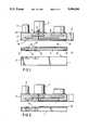
- FIG. 1is a partial cross-sectional view of a first embodiment in which the packing elements are carried by an intermediate cover member between the hydraulic connection plate and the fixed part of the regulator.
- FIG. 2is a partial cross-sectional view of a second embodiment in which the packing elements are supported directly by the upper face of the fixed part of the regulator.
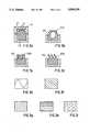
- FIGS. 3a to 3dare scrap sectional views showing different possible arrangements for the packing elements.
- FIGS. 3e to 3iare scrap top views of other possible arrangements for the packing elements similar to those of FIGS. 3c and 3d.
- FIG. 1shows a diagrammatic representation of a regulator having a fixed hydromechanical part 1 on which there are placed a plurality of electrohydraulic or electropneumatic elements 2 such as electrovalves, solenoid valves or the like.
- the elements 2are all arranged on the outer face of a connection plate 3 which is provided with all the hydraulic and pneumatic passages 4 necessary for connecting the hydraulic and pneumatic circuits of the elements 2 to the corresponding inputs 5 of the fixed part 1 of the regulator.
- connection plate 3may be made, for example, from superimposed metal sheets into which the passages 4 have been machined, for example by electroerosion or electrochemical machining, the sheets then being diffusion welded together to form the plate 3.
- the wires 6 for electrically connecting the elements 2 to an overall connector 8 of the regulatorpass through holes 7 in the plate 3 and thence along channels 9 formed in the lower surface 3a of the plate 3.
- the leadsare arranged to be pressed against the bottom of the channels by means of vibration damping packing elements 10 which, in the embodiment of FIG. 1, are bonded or otherwise fixed on the upper face 11a of an intermediate plate 11 in positions corresponding to the channels 9, the intermediate plate 11 constituting a cover and being screwed to the lower surface 3a of the connection plate as indicated at 12.
- connection plate 3 and the cover 11is suitably fixed on the fixed part 1 of the regulator.
- an intermediate cover plate 11is not used and the flexible packing elements 10 are bonded or otherwise fixed directly onto the upper face 1a of the fixed regulator part 1.
- FIGS. 3a to 3iVarious types of vibration damping packing elements which may be used to compress the wires 6 in the channels 9 are shown in FIGS. 3a to 3i.
- FIG. 3ashows the use of a solid element 110 made of a compressible material.
- the element 110is housed and glued in a groove in the surface of its support member (i.e. the cover plate 11 or the fixed part 1 of the regulator) and has a projecting part which will occupy the free space of a channel 9 fitted with its electrical cables 6.
- FIG. 3billustrates a hollow element 210 having a flexible upper part 210a which can be crushed against the cables 6.
- FIGS. 3c and 3dillustrate other possible alternatives comprising a solid part 410 housed in the support member groove, and flexible elements mounted on the solid part for engaging the electrical cables 6 in a channel 9.
- the flexible elementsare shown as vertical deformable ribs 410a, and in FIG. 3d they are shown as slanting ribs 410b.
- FIGS. 3e to 3hshow further possible embodiments of the packing elements which are similar to the embodiments of FIGS. 3c and 3d except for the arrangement of the flexible ribs.
- the elementhas a single sinusoidally shaped deformable rib, whereas in the embodiment of FIG. 3f there are several ribs oriented diagonally relative to the axis of the packing element. In the case of the embodiments shown in FIGS. 3g and 3h the ribs are respectively arranged transversely and axially relative to the axis of the element.
- FIG. 3ishows a packing element in which the flexible ribs are replaced by flexible or compressible fingers or pimples.
- connection plate 3 and the fixed regulator part 1The sealing of the hydraulic or pneumatic circuits at the junction between the connection plate 3 and the fixed regulator part 1 or the junctions between the intermediate plate 11 and both the connection plate 3 and the fixed part 1 is effected by seals 13 glued or vulcanized around the hydraulic or pneumatic ports of the fixed regulator part 1, and/or the intermediate plate 11, and/or on the connection plate 3 as appropriate.
- the arrangement in accordance with the invention as just describedfacilitates servicing of the regulators in the workshop, as it ensures interchangeability both of the fixed part and of the connection plate fitted with the electrohydraulic elements, while also ensuring that in operation the hydraulic connections are made tightly and the electrical connections are made without wear to the cables.
Landscapes
- Engineering & Computer Science (AREA)
- Physics & Mathematics (AREA)
- Fluid Mechanics (AREA)
- Mechanical Engineering (AREA)
- General Engineering & Computer Science (AREA)
- Connector Housings Or Holding Contact Members (AREA)
- Machine Tool Units (AREA)
- Sealing Devices (AREA)
Abstract
Description
1. Field of the invention
The present invention relates to regulating devices, especially for turboshaft engines for aircraft, and more particularly to regulators in which all the hydromechanical functions are integrated in one part, termed a fixed part, and the electrohydraulic functions are carried out by external components rigidly secured to the fixed part and connected electrically to sources of current and hydraulically to the fixed part of the regulator.
2. Summary of the prior art
The electrical connections of these electrohydraulic components are usually external to the regulator and to the hydraulic connection plate which may be fitted between the components and the fixed part of the regulator, and are made by means of electrical cables and connectors arranged on the faces of the equipment remote from the fixed part or on the side faces of the components.
The unit with the cabling is heavy, cumbersome and difficult to handle, and the assembly or taking down of the regulator involves connecting or disconnecting the electrical connections. These tasks take up a lot of time, are detrimental to the reliability of the unit and increase the risk of damaging the connectors and cables, which are very expensive to replace.
It would therefore be useful to be able to make the connections of the external electrohydraulic elements on the regulator or its hydraulic connection plate in a manner simultaneous with the positioning of the outer elements on the regulator. It would also be useful to be able to reduce the number of the necessary electric connectors, as well as the size of the cables, so as to make maintenance work on the regulator faster, more reliable and less costly.
In this respect, French Specification No. 2 592 432 has proposed regrouping all of the external electrohydraulic or electropneumatic equipment on the same flat surface of the regulator, and interposing between the fixed part and the external equipment an electrical connection plate constituted by a metallized printed circuit board. The hydraulic connections are made in a fluid-tight manner between the equipment and the fixed part through apertures in the printed circuit board.
However, this arrangement has a certain number of drawbacks as the printed circuit board has been found to be fragile under compression and, in addition, has a tendency to swell in contact with fuel. After a certain period of use, this may lead to the metallized areas of the board losing adherence. Moreover, such an arrangement requires contact means between the wires and the printed circuit which should be self-cleaning and, inevitably, form a weak point in the electrical circuit.
With the aim of avoiding these drawbacks, according to the present invention there is provided a regulator, for example for an aircraft turbojet engine, comprising a fixed hydromechanical part, a number of external electrohydraulic elements having at least one electrical circuit and at least one hydraulic circuit, and a hydraulic connection plate disposed between the electrohydraulic elements and the fixed hydromechanical part, the electrohydraulic elements being mounted on a first face of the hydraulic connection plate remote from the fixed hydromechanical part, and the hydraulic connection plate having fluid passage means for communicating the hydraulic circuits of the electrohydraulic elements with respective circuits of the fixed hydromechanical part, the hydraulic connection plate also having means for the passage of electric cables for connecting the electrical circuits of the electrohydraulic elements to an overall electrical connector of the regulator, the cable passage means including channels in a second face of the hydraulic connection plate opposite the first face on which the electrohydraulic elements are mounted, and the regulator including a cover forming member placed against the second face of the hydraulic connection plate containing the channels, the cover forming member carrying packing elements which project into the channels to hold the electrical cables at the bottom thereof.
Thus, the invention proposes making use of normal cables for the electrical connections between the electrohydraulic elements and the overall central connector of the regulator, and housing them in channels in a hydraulic connection plate between the elements and the fixed part of the regulator, the cables being held in the channels by vibration damping packing elements to prevent them suffering the drawbacks inherent with any cabling in turbojet engines, i.e. premature wear due to friction caused by vibrations.
The cover forming member may be an intermediate plate disposed between the hydraulic connection plate and the fixed hydromechanical part of the regulator, the intermediate plate having holes through which the fluid passage means of the hydraulic connection plate communicate with the respective circuits of the fixed hydromechanical part, and the packing elements being fixed to the face of the intermediate plate facing the second face of the hydraulic connection plate in positions corresponding to the cable channels.
Alternatively, the cover forming member may be the fixed hydromechanical part of the regulator, and the packing elements are fixed to the face of the fixed hydromechanical part facing the second face of the hydraulic connection plate in positions corresponding to the cable channels.
Various embodiments of the invention will now be described, by way of example, with reference to the accompanying drawings.
FIG. 1 is a partial cross-sectional view of a first embodiment in which the packing elements are carried by an intermediate cover member between the hydraulic connection plate and the fixed part of the regulator.
FIG. 2 is a partial cross-sectional view of a second embodiment in which the packing elements are supported directly by the upper face of the fixed part of the regulator.
FIGS. 3a to 3d are scrap sectional views showing different possible arrangements for the packing elements.
FIGS. 3e to 3i are scrap top views of other possible arrangements for the packing elements similar to those of FIGS. 3c and 3d.
FIG. 1 shows a diagrammatic representation of a regulator having a fixed hydromechanical part 1 on which there are placed a plurality of electrohydraulic or electropneumatic elements 2 such as electrovalves, solenoid valves or the like. The elements 2 are all arranged on the outer face of aconnection plate 3 which is provided with all the hydraulic andpneumatic passages 4 necessary for connecting the hydraulic and pneumatic circuits of the elements 2 to the corresponding inputs 5 of the fixed part 1 of the regulator.
Theconnection plate 3 may be made, for example, from superimposed metal sheets into which thepassages 4 have been machined, for example by electroerosion or electrochemical machining, the sheets then being diffusion welded together to form theplate 3.
The wires 6 for electrically connecting the elements 2 to anoverall connector 8 of the regulator pass through holes 7 in theplate 3 and thence alongchannels 9 formed in thelower surface 3a of theplate 3. In order to prevent frictional wear of the electrical leads 6 in thechannels 9, the leads are arranged to be pressed against the bottom of the channels by means of vibrationdamping packing elements 10 which, in the embodiment of FIG. 1, are bonded or otherwise fixed on the upper face 11a of an intermediate plate 11 in positions corresponding to thechannels 9, the intermediate plate 11 constituting a cover and being screwed to thelower surface 3a of the connection plate as indicated at 12.
The assembly formed by theconnection plate 3 and the cover 11 is suitably fixed on the fixed part 1 of the regulator.
In the alternative embodiment shown in FIG. 2, an intermediate cover plate 11 is not used and theflexible packing elements 10 are bonded or otherwise fixed directly onto the upper face 1a of the fixed regulator part 1.
Various types of vibration damping packing elements which may be used to compress the wires 6 in thechannels 9 are shown in FIGS. 3a to 3i.
FIG. 3a shows the use of a solid element 110 made of a compressible material. The element 110 is housed and glued in a groove in the surface of its support member (i.e. the cover plate 11 or the fixed part 1 of the regulator) and has a projecting part which will occupy the free space of achannel 9 fitted with its electrical cables 6.
FIG. 3b illustrates ahollow element 210 having a flexibleupper part 210a which can be crushed against the cables 6.
FIGS. 3c and 3d illustrate other possible alternatives comprising asolid part 410 housed in the support member groove, and flexible elements mounted on the solid part for engaging the electrical cables 6 in achannel 9. In FIG. 3c the flexible elements are shown as verticaldeformable ribs 410a, and in FIG. 3d they are shown asslanting ribs 410b.
FIGS. 3e to 3h show further possible embodiments of the packing elements which are similar to the embodiments of FIGS. 3c and 3d except for the arrangement of the flexible ribs.
In the embodiment of FIG. 3e the element has a single sinusoidally shaped deformable rib, whereas in the embodiment of FIG. 3f there are several ribs oriented diagonally relative to the axis of the packing element. In the case of the embodiments shown in FIGS. 3g and 3h the ribs are respectively arranged transversely and axially relative to the axis of the element.
FIG. 3i shows a packing element in which the flexible ribs are replaced by flexible or compressible fingers or pimples.
The sealing of the hydraulic or pneumatic circuits at the junction between theconnection plate 3 and the fixed regulator part 1 or the junctions between the intermediate plate 11 and both theconnection plate 3 and the fixed part 1 is effected byseals 13 glued or vulcanized around the hydraulic or pneumatic ports of the fixed regulator part 1, and/or the intermediate plate 11, and/or on theconnection plate 3 as appropriate.
The arrangement in accordance with the invention as just described facilitates servicing of the regulators in the workshop, as it ensures interchangeability both of the fixed part and of the connection plate fitted with the electrohydraulic elements, while also ensuring that in operation the hydraulic connections are made tightly and the electrical connections are made without wear to the cables.
Claims (7)
1. A regulator, for example for an aircraft turbojet engine, comprising a fixed hydromechanical part, a number of external electrohydraulic elements having at least one electrical circuit and at least one hydraulic circuit, and a hydraulic connection plate having opposed first and second faces disposed between said electrohydraulic elements and said fixed hydromechanical part, said electrohydraulic elements being mounted on said first face of said hydraulic connection plate remote from said fixed hydromechanical part, and said hydraulic connection plate having fluid passage means for communicating said hydraulic circuits of said electrohydraulic elements with respective circuits of said fixed hydromechanical part, said hydraulic connection plate also having means for the passage of electric cables for connecting said electrical circuits of said electrohydraulic elements to an overall electrical connector of said regulator, the cable passage means including channels in said second face of said hydraulic connection plate opposite said first face on which said electrohydraulic elements are mounted, and said regulator including a cover forming member placed against said second face of said hydraulic connection plate containing said channels said cover forming member carrying packing elements which project into said channels to hold said electrical cables at the bottom thereof.
2. A regulator according to claim 1, wherein said cover forming member is an intermediate plate disposed between said hydraulic connection plate and said fixed hydromechanical part of the regulator, said intermediate plate having holes through which said fluid passage means of said hydraulic connection plate communicate with the respective circuits of said fixed hydromechanical part, and said packing elements are fixed to the face of said intermediate Plate facing said second face of said hydraulic connection plate in positions corresponding to said cable channels.
3. A regulator according to claim 1, wherein said cover forming member is said fixed hydromechanical part of said regulator, and said packing elements are fixed to the face of said fixed hydromechanical part facing said second face of said hydraulic connection plate in positions corresponding to said cable channels.
4. A regulator according to claim 1, wherein said packing elements are flexible.
5. A regulator according to claim 4, wherein said packing elements are made of a compressible material.
6. A regulator according to claim 4, wherein said packing elements comprise a solid base part and flexible members mounted on said base part.
7. A regulator according to claim 6, wherein said flexible members comprise deformable ribs.
Applications Claiming Priority (2)
| Application Number | Priority Date | Filing Date | Title |
|---|---|---|---|
| FR9004989AFR2661214B1 (en) | 1990-04-19 | 1990-04-19 | ELECTROHYDRAULIC CONNECTION PLATE FOR TURBOMACHINE REGULATOR. |
| FR9004989 | 1990-04-19 |
Publications (1)
| Publication Number | Publication Date |
|---|---|
| US5094268Atrue US5094268A (en) | 1992-03-10 |
Family
ID=9395883
Family Applications (1)
| Application Number | Title | Priority Date | Filing Date |
|---|---|---|---|
| US07/684,280Expired - LifetimeUS5094268A (en) | 1990-04-19 | 1991-04-12 | Regulator having an electrohydraulic connection plate |
Country Status (3)
| Country | Link |
|---|---|
| US (1) | US5094268A (en) |
| FR (1) | FR2661214B1 (en) |
| GB (1) | GB2243410B (en) |
Cited By (17)
| Publication number | Priority date | Publication date | Assignee | Title |
|---|---|---|---|---|
| US5403077A (en)* | 1991-03-09 | 1995-04-04 | Alfred Teves Gmbh | Hydraulic assembly |
| US5529389A (en)* | 1990-03-30 | 1996-06-25 | Akebono Brake Industry Co., Ltd. | Brake control unit |
| US5640995A (en)* | 1995-03-14 | 1997-06-24 | Baxter International Inc. | Electrofluidic standard module and custom circuit board assembly |
| US20040119038A1 (en)* | 2002-12-20 | 2004-06-24 | Applied Materials, Inc. | Micromachined integrated fluid delivery system with dynamic metal seat valve and other components |
| US6776395B1 (en)* | 1999-12-08 | 2004-08-17 | Bosch Rexroth Ag | Proportional valve that can be actuated electromagnetically |
| US20070051080A1 (en)* | 2002-12-20 | 2007-03-08 | Applied Materials, Inc. | In-line filter in a diffusion bonded layered substrate |
| US20070295401A1 (en)* | 2004-09-17 | 2007-12-27 | Ckd Coroporation | Flow Path Block |
| US20080202614A1 (en)* | 2007-02-26 | 2008-08-28 | Ckd Corporation | Passage block and manufacturing method thereof |
| US20080289711A1 (en)* | 2007-05-24 | 2008-11-27 | Rti Technologies, Inc. | Fluid handling apparatus, manifold therefor and method of making same |
| US20080296351A1 (en)* | 2007-05-31 | 2008-12-04 | Mark Crockett | Diffusion bonded fluid flow apparatus useful in semiconductor manufacturing |
| US20080296354A1 (en)* | 2007-05-31 | 2008-12-04 | Mark Crockett | Stainless steel or stainless steel alloy for diffusion bonding |
| WO2008157340A3 (en)* | 2007-06-13 | 2009-02-12 | Gkn Sinter Metals Inc | Powder metal component tolerance improvements |
| US20130223580A1 (en)* | 2012-02-27 | 2013-08-29 | Scott J Shargots | Control rod drive mechanism (crdm) mounting system for pressurized water reactors |
| US8534594B2 (en) | 2011-04-11 | 2013-09-17 | Gulfstream Aerospace Corporation | Vibration isolation system using electrical cables as mass |
| US20130301785A1 (en)* | 2012-04-17 | 2013-11-14 | Babcock & Wilcox Mpower Inc | Suspended upper internals for compact nuclear reactor including a mid-hanger plate |
| CN104520938A (en)* | 2012-04-17 | 2015-04-15 | 巴布科克和威尔科克斯M能量股份有限公司 | CRDM internal electrical connector |
| US9911512B2 (en) | 2012-02-27 | 2018-03-06 | Bwxt Mpower, Inc. | CRDM internal electrical connector |
Families Citing this family (1)
| Publication number | Priority date | Publication date | Assignee | Title |
|---|---|---|---|---|
| CN103303575A (en)* | 2013-07-08 | 2013-09-18 | 苏州苏越电气有限公司 | Improved cable assembly |
Citations (9)
| Publication number | Priority date | Publication date | Assignee | Title |
|---|---|---|---|---|
| US3814126A (en)* | 1971-09-15 | 1974-06-04 | Samson Apparatebau Ag | Fluid conducting system |
| US4348942A (en)* | 1979-08-21 | 1982-09-14 | Kurt Stoll | Pressure-medium connection between a valve block and a load which has at least one double-acting pressure-medium motor |
| US4378027A (en)* | 1980-04-02 | 1983-03-29 | Gewerkschaft Eisenhutte Westfalia | Control unit for an electro-hydraulic roof support control arrangement |
| US4399836A (en)* | 1981-04-14 | 1983-08-23 | Marotta Scientific Controls, Inc. | Self-contained closed-loop electrically operated valve |
| US4527589A (en)* | 1982-04-28 | 1985-07-09 | Kurt Stoll | Valve assembly |
| FR2592432A1 (en)* | 1985-12-30 | 1987-07-03 | Snecma | REGULATOR, ESPECIALLY FOR A TURBOMACHINE, WITH QUICK-ASSEMBLY ELECTROHYDRAULIC INTERFACE |
| US4815496A (en)* | 1986-12-29 | 1989-03-28 | Smc Corporation | Power feeder for solenoid valves |
| US4842021A (en)* | 1984-07-26 | 1989-06-27 | Kurt Stoll | Support for fluid power devices |
| US5025834A (en)* | 1988-08-16 | 1991-06-25 | Festo Kg | Mounting plate storing conductor function |
Family Cites Families (1)
| Publication number | Priority date | Publication date | Assignee | Title |
|---|---|---|---|---|
| DE3431163A1 (en)* | 1984-08-24 | 1986-03-06 | Festo KG, 7300 Esslingen | SWITCHING UNIT |
- 1990
- 1990-04-19FRFR9004989Apatent/FR2661214B1/ennot_activeExpired - Lifetime
- 1991
- 1991-03-28GBGB9106611Apatent/GB2243410B/ennot_activeExpired - Fee Related
- 1991-04-12USUS07/684,280patent/US5094268A/ennot_activeExpired - Lifetime
Patent Citations (9)
| Publication number | Priority date | Publication date | Assignee | Title |
|---|---|---|---|---|
| US3814126A (en)* | 1971-09-15 | 1974-06-04 | Samson Apparatebau Ag | Fluid conducting system |
| US4348942A (en)* | 1979-08-21 | 1982-09-14 | Kurt Stoll | Pressure-medium connection between a valve block and a load which has at least one double-acting pressure-medium motor |
| US4378027A (en)* | 1980-04-02 | 1983-03-29 | Gewerkschaft Eisenhutte Westfalia | Control unit for an electro-hydraulic roof support control arrangement |
| US4399836A (en)* | 1981-04-14 | 1983-08-23 | Marotta Scientific Controls, Inc. | Self-contained closed-loop electrically operated valve |
| US4527589A (en)* | 1982-04-28 | 1985-07-09 | Kurt Stoll | Valve assembly |
| US4842021A (en)* | 1984-07-26 | 1989-06-27 | Kurt Stoll | Support for fluid power devices |
| FR2592432A1 (en)* | 1985-12-30 | 1987-07-03 | Snecma | REGULATOR, ESPECIALLY FOR A TURBOMACHINE, WITH QUICK-ASSEMBLY ELECTROHYDRAULIC INTERFACE |
| US4815496A (en)* | 1986-12-29 | 1989-03-28 | Smc Corporation | Power feeder for solenoid valves |
| US5025834A (en)* | 1988-08-16 | 1991-06-25 | Festo Kg | Mounting plate storing conductor function |
Cited By (42)
| Publication number | Priority date | Publication date | Assignee | Title |
|---|---|---|---|---|
| US5529389A (en)* | 1990-03-30 | 1996-06-25 | Akebono Brake Industry Co., Ltd. | Brake control unit |
| US5403077A (en)* | 1991-03-09 | 1995-04-04 | Alfred Teves Gmbh | Hydraulic assembly |
| US5640995A (en)* | 1995-03-14 | 1997-06-24 | Baxter International Inc. | Electrofluidic standard module and custom circuit board assembly |
| US6776395B1 (en)* | 1999-12-08 | 2004-08-17 | Bosch Rexroth Ag | Proportional valve that can be actuated electromagnetically |
| US7559527B2 (en) | 2002-12-20 | 2009-07-14 | Applied Materials, Inc. | Diffusion bonded fluid flow manifold with partially integrated inter-active component |
| US7850786B2 (en) | 2002-12-20 | 2010-12-14 | Applied Materials, Inc. | Method of improving corrosion resistance of stainless steel surfaces by a process of passivation |
| US20070062909A1 (en)* | 2002-12-20 | 2007-03-22 | Applied Materials, Inc. | Method of improving corrosion resistance of stainless steel surfaces by a process of passivation |
| US20070062021A1 (en)* | 2002-12-20 | 2007-03-22 | Applied Materials, Inc. | Method of attaching components to semiconductor processing chambers using diffusion bonding |
| US20070113663A1 (en)* | 2002-12-20 | 2007-05-24 | Applied Materials, Inc. | Capacitance dual electrode pressure sensor in a diffusion bonded layered substrate |
| US20070200082A1 (en)* | 2002-12-20 | 2007-08-30 | Applied Materials, Inc. | Manufacture of an integrated fluid delivery system for semiconductor processing apparatus |
| US20070226973A1 (en)* | 2002-12-20 | 2007-10-04 | Applied Materials, Inc. | Diffusion bonded fluid flow manifold with partially integrated inter-active component |
| US20070051080A1 (en)* | 2002-12-20 | 2007-03-08 | Applied Materials, Inc. | In-line filter in a diffusion bonded layered substrate |
| CN1729369B (en)* | 2002-12-20 | 2010-04-28 | 应用材料股份有限公司 | Integrated fluid delivery system with dynamic metal valve seat and other components |
| US7448276B2 (en) | 2002-12-20 | 2008-11-11 | Applied Materials, Inc. | Capacitance dual electrode pressure sensor in a diffusion bonded layered substrate |
| US20040119038A1 (en)* | 2002-12-20 | 2004-06-24 | Applied Materials, Inc. | Micromachined integrated fluid delivery system with dynamic metal seat valve and other components |
| US7459003B2 (en) | 2002-12-20 | 2008-12-02 | Applied Materials, Inc. | In-line filter in a diffusion bonded layered substrate |
| US8020750B2 (en) | 2002-12-20 | 2011-09-20 | Applied Materials, Inc. | Method of attaching components to fluid delivery systems using diffusion bonding |
| US8017028B2 (en) | 2002-12-20 | 2011-09-13 | Applied Materials, Inc. | Method of increasing etchability of metals having chemical etching resistant microstructure |
| US7984891B2 (en) | 2002-12-20 | 2011-07-26 | Applied Materials, Inc. | Manufacture of an integrated fluid delivery system for semiconductor processing apparatus |
| US20090039057A1 (en)* | 2002-12-20 | 2009-02-12 | Applied Materials, Inc. | Method of increasing etchability of metals having chemical etching resistant microstructure |
| US20070295401A1 (en)* | 2004-09-17 | 2007-12-27 | Ckd Coroporation | Flow Path Block |
| US20080202614A1 (en)* | 2007-02-26 | 2008-08-28 | Ckd Corporation | Passage block and manufacturing method thereof |
| US20080289711A1 (en)* | 2007-05-24 | 2008-11-27 | Rti Technologies, Inc. | Fluid handling apparatus, manifold therefor and method of making same |
| US7726343B2 (en)* | 2007-05-24 | 2010-06-01 | Rti Technologies, Inc. | Fluid handling apparatus, manifold therefor and method of making same |
| US7798388B2 (en) | 2007-05-31 | 2010-09-21 | Applied Materials, Inc. | Method of diffusion bonding a fluid flow apparatus |
| US20080296354A1 (en)* | 2007-05-31 | 2008-12-04 | Mark Crockett | Stainless steel or stainless steel alloy for diffusion bonding |
| US20080296351A1 (en)* | 2007-05-31 | 2008-12-04 | Mark Crockett | Diffusion bonded fluid flow apparatus useful in semiconductor manufacturing |
| WO2008157340A3 (en)* | 2007-06-13 | 2009-02-12 | Gkn Sinter Metals Inc | Powder metal component tolerance improvements |
| CN101715522B (en)* | 2007-06-13 | 2013-07-31 | Gkn烧结金属有限公司 | Improvements to Tolerances for Powder Metal Components |
| US20110143158A1 (en)* | 2007-06-13 | 2011-06-16 | Donaldson Ian W | Powder metal component tolerance improvements |
| US8636264B2 (en) | 2007-06-13 | 2014-01-28 | Gkn Sinter Metals, Llc | Powder metal component tolerance improvements |
| US8534594B2 (en) | 2011-04-11 | 2013-09-17 | Gulfstream Aerospace Corporation | Vibration isolation system using electrical cables as mass |
| US9805832B2 (en)* | 2012-02-27 | 2017-10-31 | Bwxt Mpower, Inc. | Control rod drive mechanism (CRDM) mounting system for pressurized water reactors |
| CN103295653A (en)* | 2012-02-27 | 2013-09-11 | 巴布科克和威尔科克斯核能股份有限公司 | Control rod drive mechanism (CRDM) mounting system for pressurized water reactors |
| US20130223580A1 (en)* | 2012-02-27 | 2013-08-29 | Scott J Shargots | Control rod drive mechanism (crdm) mounting system for pressurized water reactors |
| US9911512B2 (en) | 2012-02-27 | 2018-03-06 | Bwxt Mpower, Inc. | CRDM internal electrical connector |
| US10629313B2 (en) | 2012-02-27 | 2020-04-21 | Bwxt Mpower, Inc. | Control rod drive mechanism (CRDM) mounting method for pressurized water reactors |
| US10943705B2 (en) | 2012-02-27 | 2021-03-09 | Bwxt Mpower, Inc. | CRDM internal electrical connector and method of use thereof |
| US11342082B2 (en) | 2012-02-27 | 2022-05-24 | Bwxt Mpower, Inc. | Control rod drive mechanism (CRDM) mounting method for pressurized water reactors |
| US20130301785A1 (en)* | 2012-04-17 | 2013-11-14 | Babcock & Wilcox Mpower Inc | Suspended upper internals for compact nuclear reactor including a mid-hanger plate |
| CN104520938A (en)* | 2012-04-17 | 2015-04-15 | 巴布科克和威尔科克斯M能量股份有限公司 | CRDM internal electrical connector |
| US9767930B2 (en)* | 2012-04-17 | 2017-09-19 | Bwxt Mpower, Inc. | Suspended upper internals for compact nuclear reactor including a mid-hanger plate |
Also Published As
| Publication number | Publication date |
|---|---|
| GB9106611D0 (en) | 1991-05-15 |
| FR2661214A1 (en) | 1991-10-25 |
| GB2243410A (en) | 1991-10-30 |
| GB2243410B (en) | 1993-07-21 |
| FR2661214B1 (en) | 1992-07-03 |
Similar Documents
| Publication | Publication Date | Title |
|---|---|---|
| US5094268A (en) | Regulator having an electrohydraulic connection plate | |
| US5061193A (en) | Electrical connection arrangement and method of providing an electrical connection | |
| US5766026A (en) | Electrical connector assembly with sealed and spring biased electrical component | |
| US5035637A (en) | Engine valve cover gasket with electrical bridge | |
| US5452948A (en) | Apparatus and method for electronically controlled hydraulic actuator | |
| US5596148A (en) | Pressure difference measurement transducer with electric lead-through in bore parallel to housing longitudinal axis | |
| US20040095732A1 (en) | Housing structure of vehicle-mounted electronic equipment | |
| EP0370080A1 (en) | Electrohydraulic pressure-control device. | |
| US6679568B1 (en) | Block-protected braking system | |
| US5823070A (en) | Automatic transmission | |
| US4262166A (en) | Sealed inlet for bunched conductors | |
| US5895027A (en) | Solenoid unit for an automatic transmission unit | |
| JP5054534B2 (en) | Cylinder head gasket with integrated sensor | |
| US4095863A (en) | Manifold means and system for electrical and/or pneumatic control devices and method | |
| US20040089352A1 (en) | Board-mounted manifold valve | |
| CA2453029A1 (en) | Electro-hydraulic manifold assembly and pressure sensor therefor | |
| US6863566B2 (en) | Subassembly with a plug-in housing connector | |
| US4126883A (en) | Pressure-mounted semiconductive structure | |
| US4726778A (en) | Electrical and hydraulic connections assembly for an electro-hydraulic governor | |
| JPH10332018A (en) | Solenoid valve mounting structure for hydraulic control device | |
| GB1414296A (en) | Cable glands | |
| MX163917B (en) | CERAMIC SEALANT ASSEMBLY | |
| SU1654908A1 (en) | Cable lead-in | |
| CN116373138B (en) | Dicing saw | |
| KR100577035B1 (en) | Pressure sensor unit |
Legal Events
| Date | Code | Title | Description |
|---|---|---|---|
| AS | Assignment | Owner name:SOCIETE NATIONALE D'ETUDE ET DE CONSTRUCTION DE MO Free format text:ASSIGNMENT OF ASSIGNORS INTEREST.;ASSIGNORS:MOREL, MICHEL M. J.;TRENET, ROLAND;REEL/FRAME:005951/0837 Effective date:19910403 | |
| STCF | Information on status: patent grant | Free format text:PATENTED CASE | |
| FEPP | Fee payment procedure | Free format text:PAYOR NUMBER ASSIGNED (ORIGINAL EVENT CODE: ASPN); ENTITY STATUS OF PATENT OWNER: LARGE ENTITY | |
| FPAY | Fee payment | Year of fee payment:4 | |
| FPAY | Fee payment | Year of fee payment:8 | |
| FPAY | Fee payment | Year of fee payment:12 | |
| AS | Assignment | Owner name:SNECMA MOTEURS, FRANCE Free format text:CHANGE OF NAME;ASSIGNOR:SOCIETE NATIONALE D'ETUDES ET DE CONSTRUCTION DE MOTEURS D'AVIATION;REEL/FRAME:014754/0192 Effective date:20000117 | |
| AS | Assignment | Owner name:HISPANO-SUIZA, FRANCE Free format text:ASSIGNMENT OF ASSIGNORS INTEREST;ASSIGNOR:SNECMA MOTEURS;REEL/FRAME:020487/0852 Effective date:20020222 |