US5093885A - Fiber optic connector module - Google Patents
Fiber optic connector moduleDownload PDFInfo
- Publication number
- US5093885A US5093885AUS07/671,989US67198991AUS5093885AUS 5093885 AUS5093885 AUS 5093885AUS 67198991 AUS67198991 AUS 67198991AUS 5093885 AUS5093885 AUS 5093885A
- Authority
- US
- United States
- Prior art keywords
- panel
- interior
- connectors
- connector
- optical fibers
- Prior art date
- Legal status (The legal status is an assumption and is not a legal conclusion. Google has not performed a legal analysis and makes no representation as to the accuracy of the status listed.)
- Expired - Fee Related
Links
Images


Classifications
- G—PHYSICS
- G02—OPTICS
- G02B—OPTICAL ELEMENTS, SYSTEMS OR APPARATUS
- G02B6/00—Light guides; Structural details of arrangements comprising light guides and other optical elements, e.g. couplings
- G02B6/44—Mechanical structures for providing tensile strength and external protection for fibres, e.g. optical transmission cables
- G02B6/4439—Auxiliary devices
- G02B6/444—Systems or boxes with surplus lengths
- G02B6/4453—Cassettes
- G02B6/4454—Cassettes with splices
- G—PHYSICS
- G02—OPTICS
- G02B—OPTICAL ELEMENTS, SYSTEMS OR APPARATUS
- G02B6/00—Light guides; Structural details of arrangements comprising light guides and other optical elements, e.g. couplings
- G02B6/44—Mechanical structures for providing tensile strength and external protection for fibres, e.g. optical transmission cables
- G02B6/4439—Auxiliary devices
- G02B6/444—Systems or boxes with surplus lengths
- G02B6/4452—Distribution frames
- G02B6/44526—Panels or rackmounts covering a whole width of the frame or rack
- G—PHYSICS
- G02—OPTICS
- G02B—OPTICAL ELEMENTS, SYSTEMS OR APPARATUS
- G02B6/00—Light guides; Structural details of arrangements comprising light guides and other optical elements, e.g. couplings
- G02B6/44—Mechanical structures for providing tensile strength and external protection for fibres, e.g. optical transmission cables
- G02B6/4439—Auxiliary devices
- G02B6/444—Systems or boxes with surplus lengths
- G02B6/44528—Patch-cords; Connector arrangements in the system or in the box
- G—PHYSICS
- G02—OPTICS
- G02B—OPTICAL ELEMENTS, SYSTEMS OR APPARATUS
- G02B6/00—Light guides; Structural details of arrangements comprising light guides and other optical elements, e.g. couplings
- G02B6/44—Mechanical structures for providing tensile strength and external protection for fibres, e.g. optical transmission cables
- G02B6/4439—Auxiliary devices
- G02B6/444—Systems or boxes with surplus lengths
- G02B6/4453—Cassettes
- G02B6/4455—Cassettes characterised by the way of extraction or insertion of the cassette in the distribution frame, e.g. pivoting, sliding, rotating or gliding
Definitions
- This applicationpertains to a fiber optic connector module. More particularly, this application pertains to a fiber optic connector module having both connector and splicing functions.
- a fiber optic connector moduleis provided.
- the moduleincludes a chassis having a plurality of walls which define a chassis interior. An access opening is formed through the walls permitting access to the chassis interior.
- a connector panelis provided and sized to close the opening.
- the connector panelis pivotally connected to the chassis for the panel to be pivoted between an open and closed position. In the closed position, the connector panel covers the access opening. In the open position, the connector panel is pivoted away to expose the interior of the chassis and permit an operator to have access to the rear of the panel.
- a plurality of splice traysare provided carried within the interior of the cabinet and accessible when the panel is in the open position.
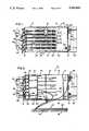
- FIG. 1is a front elevational view of a fiber optic connector module according to the present inventions with a connector panel shown in a closed position;
- FIG. 2is the view of FIG. 1 with the connector panel shown in the open position and with a splice tray removed from an interior of the module;
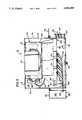
- FIG. 3is a top plan view of the module of FIG. 1 with a top wall of the chassis shown removed to expose the interior of the chassis and with a connector panel shown in a closed position;
- FIG. 4is a view of FIG. 3 with the connector panel shown in an open position and with a splice tray removed from an interior of the chassis;
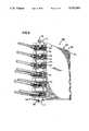
- FIG. 5is a side elevation view of the cabinet of FIG. 2 with a connector panel shown in an open position and without showing a splice tray removed from the chassis;
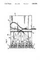
- FIG. 6is a perspective view of a modular connector pack for use in the connector module.
- FIG. 7is a view of the connector pack of FIG. 6 with the connector pack shown open to expose interior elements.
- FIGS. 1-5A fiber optic connector module 10 is shown in FIGS. 1-5.
- the module 10includes a chassis 12 having side walls 14,16, rear wall 18 and top and bottom walls 20,22 which cooperate to define a chassis interior 24.
- the chassisincludes a clear plastic front wall 26 which is connected to a forward edge of bottom wall 22 by means of a hinge 28.
- a latch 30is provided for latching an upper edge of the front wall 26 to a forward edge of the top wall 20 as shown in FIG. 1. So constructed, the front wall 26 may be unlatched and pivoted to the down position as shown in FIG. 2 to define an access opening 32 (FIG. 2) to the interior 24.
- a connector panel 34is provided sized to be received within interior 24.
- Panel 34has a forward wall 36 sized substantially to cover the access opening 32.
- An upper plate 38(FIG. 2) extends from an upper edge of wall 36 and a lower plate 40 (see FIG. 2) extends from a lower edge of wall 36.
- upper and lower hinge plates 42are provided for pivotally connecting the left side of panel 34 (when viewed in FIGS. 1 and 3) to the chassis 12.
- the hinge plates 42are disposed so the panel 34 rotates about the vertical axis defined as the dimension between the upper and lower walls 20,22.
- a plurality of shelves 44are provided extending into the interior 24 and attached to back wall 18. Shelves 44 are parallel aligned and spaced apart for each of the shelves 44 to retain and hold a splice tray assembly 50 as will be described.
- the wall 36carries a plurality of optical fiber connectors 52.
- Connectors 52 for connecting optical fibersare commercially available and form no part of this invention per se.
- Adapters 54are provided for securing the connectors 52 to the wall 36.
- Adapters such as adapters 54form no part of this invention per se and may be such as those shown and described in the aforementioned, commonly assigned, U.S. patent application Ser. No. 07/388,060 now U.S. Pat. No. 4,995,688.
- the adapters 54are connected to the wall.
- the adaptors 54are selected to retain the connectors 52 at a non-orthogonal angle to the wall 36 with the exposed connectors pointing toward the side of the chassis 12 on which the wall 36 is pivotally connected.
- a plurality of modular connectors packs 60are provided secured to the wall 36 for pivotal movement therewith.
- the packs 60carry the adapters 54 and the connectors 52. As indicated, packs 60 are preferred.
- adaptors 54can be directly mounted on wall 36.
- the packs 60include a housing 62 having a forward surface 64 and side walls 66,68 which are connected by a hinge 70.
- the wall 68is bent such that when the walls 66,68 are pivoted against one another in a closed position as shown in FIGS. 6 and 5, the housing is closed and presents both forward wall 64 and a rear wall 72 (FIG. 5).
- the adapters 54are secured to openings in the forward wall 64.
- the connectors 52are carried by the adapters 54.
- a cable or pigtail 74 of optical fibers 76is terminated with individual fibers 76 separately terminated on each of the connectors 52.
- the pack 60is a "hard wired" pack of connectors 52 with a single pigtail or cable 74 extending from the pack 60.
- the pack 60contains 12 connectors. It will be appreciated that this is a preferred embodiment only. The number may vary while retaining the essence and intent of the present invention.
- Mounting tabs 77extend from forward wall 64 and carry mounting screws 78 for connecting the pack 60 to the wall 36 as shown in FIGS. 1, 3 and 5.
- the packs 60are aligned in side-by-side relation with the pigtails 74 extending from the back side of connector panel 34 and with connectors 52 exposed on the front side of connector panel 34. (Back side referring to the side exposed to the interior of the cabinet and the front side referring to the opposite surface).
- a splice tray assembly 50is provided having a commercially available splice tray 80 connected to a spool 82.
- Spool 82is sized to permit an operator to wrap excess amounts of pigtail 74 or incoming fibers 86 around spool 82 with a radius of bending greater than a minimum radius which might otherwise damage optical fibers (for example, a radius greater than 11/2 inches).
- the optical fibers carried by pigtail 74may be spliced to incoming fibers 86. (The actual splice mechanism is not shown for purposes of clarity but will be recognized by those skilled in the art as being commercially available).
- the chassis 12includes mounting brackets 90,92 for mounting the chassis 12 to a frame (not shown).
- Clamps 94are carried on side wall 16 to hold and retain optical fiber cables. For purposes of clarity, a cable is not shown in the drawings. Instead, individual incoming fibers 86 are shown. The fibers are passed from clamp 94 through a side opening 96 formed in side wall 16 (see FIG. 5).
- Bracket 92Connected to mounting bracket 92 are clips 98 which together with bracket 92 define a trough 100 (FIGS. 3, 4) through which fiber optic patch cords 102 may be passed.
- the patch cords 102are terminated on connectors 52 and are retained in an organized manner by a fanning clip 105 carried on wall 36.
- a handle 106is provided on wall 36 and positioned to be engaged by an operator to pivot the wall about its pivot axis.
- the connector pack 60may be provided premanufactured and prewired to have a plurality of connectors 52 exposed through a front surface 64 and with a single pigtail or cable 74 extending from the individual connector pack 60.
- the pack 60is connected to wall 36 with each of the pigtails 74 having their optical fibers 76 spliced to the incoming optical fibers 86 in splice tray assembly 50. Excess amounts of both incoming fibers 86 and pigtails 74 are carried on spool 82 in a manner to prevent excessive bending of the optical fibers. Patch cord connections are accessible through the forward face of wall 36 by opening front wall 26.
- the present inventionattains both functions of splicing and connecting in a single modular assembly. Also, access to the module is through the forward face. As a result, in developing a telephone office system using the present invention, space need not be provided to permit access to the rear of the frame on which the connector module 10 is attached.
Landscapes
- Physics & Mathematics (AREA)
- General Physics & Mathematics (AREA)
- Optics & Photonics (AREA)
- Light Guides In General And Applications Therefor (AREA)
Abstract
Description
This is a continuation, of application Ser. No. 07/551,423, filed July 11, 1990, now abandoned.
1. Field of the Invention
This application pertains to a fiber optic connector module. More particularly, this application pertains to a fiber optic connector module having both connector and splicing functions.
2. Description of the Prior Art
In the telecommunications and data transmission industries, the use of optical fibers as the transmitting medium has grown dramatically. With the increased usage of optical fiber transmission paths, the industry has experienced a dramatic need for new and improved apparatus to affect fiber connections and splices as well as fiber storage. An example of such a product is shown in copending and commonly assigned U.S. patent application Ser. No. 07/388,060 now U.S. Pat. No. 4,995,688. That application shows a fiber distribution frame of modular construction. The frame includes three modularized cabinets for splicing, fiber storage and connector functions. The modularity of the design permits the user of the frame to select and subsequently modify the fiber distribution frame to meet particular design needs.
Notwithstanding the prior improvements made in the art, there is a continuing need for enhanced optical fiber connector module designs to meet specific needs of specific applications while retaining overall requirements of cost effectiveness, accessibility and ease of use. It is an object of the present invention to provide such an improved connector module.
According to a preferred embodiment of the present invention, a fiber optic connector module is provided. The module includes a chassis having a plurality of walls which define a chassis interior. An access opening is formed through the walls permitting access to the chassis interior. A connector panel is provided and sized to close the opening. The connector panel is pivotally connected to the chassis for the panel to be pivoted between an open and closed position. In the closed position, the connector panel covers the access opening. In the open position, the connector panel is pivoted away to expose the interior of the chassis and permit an operator to have access to the rear of the panel. A plurality of splice trays are provided carried within the interior of the cabinet and accessible when the panel is in the open position.
FIG. 1 is a front elevational view of a fiber optic connector module according to the present inventions with a connector panel shown in a closed position;
FIG. 2 is the view of FIG. 1 with the connector panel shown in the open position and with a splice tray removed from an interior of the module;
FIG. 3 is a top plan view of the module of FIG. 1 with a top wall of the chassis shown removed to expose the interior of the chassis and with a connector panel shown in a closed position;
FIG. 4 is a view of FIG. 3 with the connector panel shown in an open position and with a splice tray removed from an interior of the chassis;
FIG. 5 is a side elevation view of the cabinet of FIG. 2 with a connector panel shown in an open position and without showing a splice tray removed from the chassis;
FIG. 6 is a perspective view of a modular connector pack for use in the connector module; and
FIG. 7 is a view of the connector pack of FIG. 6 with the connector pack shown open to expose interior elements.
Referring now to the several drawings and figures in which identical elements are numbered identically throughout, a description of the preferred embodiment of the present invention will now be provided. A fiberoptic connector module 10 is shown in FIGS. 1-5. Themodule 10 includes achassis 12 havingside walls rear wall 18 and top andbottom walls chassis interior 24.
The chassis includes a clearplastic front wall 26 which is connected to a forward edge ofbottom wall 22 by means of ahinge 28. Alatch 30 is provided for latching an upper edge of thefront wall 26 to a forward edge of thetop wall 20 as shown in FIG. 1. So constructed, thefront wall 26 may be unlatched and pivoted to the down position as shown in FIG. 2 to define an access opening 32 (FIG. 2) to theinterior 24.
Aconnector panel 34 is provided sized to be received withininterior 24.Panel 34 has aforward wall 36 sized substantially to cover the access opening 32. An upper plate 38 (FIG. 2) extends from an upper edge ofwall 36 and a lower plate 40 (see FIG. 2) extends from a lower edge ofwall 36.
With reference to the view of FIGS. 2-4, upper andlower hinge plates 42 are provided for pivotally connecting the left side of panel 34 (when viewed in FIGS. 1 and 3) to thechassis 12. Thehinge plates 42 are disposed so thepanel 34 rotates about the vertical axis defined as the dimension between the upper andlower walls
A plurality ofshelves 44 are provided extending into theinterior 24 and attached toback wall 18. Shelves 44 are parallel aligned and spaced apart for each of theshelves 44 to retain and hold asplice tray assembly 50 as will be described.
Thewall 36 carries a plurality ofoptical fiber connectors 52.Connectors 52 for connecting optical fibers are commercially available and form no part of this invention per se.
Commercially available connectors are available in a wide variety of shapes and configurations. To accommodate this variety and add flexibility to the design of the present invention, a plurality ofadapters 54 are provided for securing theconnectors 52 to thewall 36. Adapters such asadapters 54 form no part of this invention per se and may be such as those shown and described in the aforementioned, commonly assigned, U.S. patent application Ser. No. 07/388,060 now U.S. Pat. No. 4,995,688.
As shown in the drawing figures, theadapters 54 are connected to the wall. Theadaptors 54 are selected to retain theconnectors 52 at a non-orthogonal angle to thewall 36 with the exposed connectors pointing toward the side of thechassis 12 on which thewall 36 is pivotally connected.
While theadapters 54 could be secured to thewall 36 directly, in a preferred embodiment of the present invention, a plurality ofmodular connectors packs 60 are provided secured to thewall 36 for pivotal movement therewith. Thepacks 60 carry theadapters 54 and theconnectors 52. As indicated,packs 60 are preferred. However,adaptors 54 can be directly mounted onwall 36.
As best shown in FIGS. 6 and 7, thepacks 60 include ahousing 62 having aforward surface 64 andside walls 66,68 which are connected by ahinge 70. The wall 68 is bent such that when thewalls 66,68 are pivoted against one another in a closed position as shown in FIGS. 6 and 5, the housing is closed and presents bothforward wall 64 and a rear wall 72 (FIG. 5).
Theadapters 54 are secured to openings in theforward wall 64. Theconnectors 52 are carried by theadapters 54. Within the interior of thepack 60, a cable orpigtail 74 ofoptical fibers 76 is terminated withindividual fibers 76 separately terminated on each of theconnectors 52. When closed (as shown in FIG. 6), thepack 60 is a "hard wired" pack ofconnectors 52 with a single pigtail orcable 74 extending from thepack 60. In the embodiment shown, thepack 60 contains 12 connectors. It will be appreciated that this is a preferred embodiment only. The number may vary while retaining the essence and intent of the present invention.
Mountingtabs 77 extend fromforward wall 64 and carry mountingscrews 78 for connecting thepack 60 to thewall 36 as shown in FIGS. 1, 3 and 5. When disposed in thewall 36, thepacks 60 are aligned in side-by-side relation with thepigtails 74 extending from the back side ofconnector panel 34 and withconnectors 52 exposed on the front side ofconnector panel 34. (Back side referring to the side exposed to the interior of the cabinet and the front side referring to the opposite surface).
Asplice tray assembly 50 is provided having a commerciallyavailable splice tray 80 connected to aspool 82.Spool 82 is sized to permit an operator to wrap excess amounts ofpigtail 74 orincoming fibers 86 aroundspool 82 with a radius of bending greater than a minimum radius which might otherwise damage optical fibers (for example, a radius greater than 11/2 inches). Withinsplice tray 80, the optical fibers carried bypigtail 74 may be spliced toincoming fibers 86. (The actual splice mechanism is not shown for purposes of clarity but will be recognized by those skilled in the art as being commercially available).
Thechassis 12 includes mountingbrackets chassis 12 to a frame (not shown).Clamps 94 are carried onside wall 16 to hold and retain optical fiber cables. For purposes of clarity, a cable is not shown in the drawings. Instead, individualincoming fibers 86 are shown. The fibers are passed fromclamp 94 through aside opening 96 formed in side wall 16 (see FIG. 5).
Connected to mountingbracket 92 areclips 98 which together withbracket 92 define a trough 100 (FIGS. 3, 4) through which fiberoptic patch cords 102 may be passed. Thepatch cords 102 are terminated onconnectors 52 and are retained in an organized manner by a fanningclip 105 carried onwall 36. Ahandle 106 is provided onwall 36 and positioned to be engaged by an operator to pivot the wall about its pivot axis.
With the invention thus described, theconnector pack 60 may be provided premanufactured and prewired to have a plurality ofconnectors 52 exposed through afront surface 64 and with a single pigtail orcable 74 extending from theindividual connector pack 60. Thepack 60 is connected to wall 36 with each of thepigtails 74 having theiroptical fibers 76 spliced to the incomingoptical fibers 86 insplice tray assembly 50. Excess amounts of bothincoming fibers 86 andpigtails 74 are carried onspool 82 in a manner to prevent excessive bending of the optical fibers. Patch cord connections are accessible through the forward face ofwall 36 by openingfront wall 26. Accordingly, the present invention attains both functions of splicing and connecting in a single modular assembly. Also, access to the module is through the forward face. As a result, in developing a telephone office system using the present invention, space need not be provided to permit access to the rear of the frame on which theconnector module 10 is attached.
Through the foregoing description of the preferred embodiment, it has been shown how the objects of the present invention have been achieved. However, modifications and equivalents of the disclosed concepts, such as those which would readily occur to one skilled in the art, are intended to be included within the scope of protection.
Claims (7)
1. A fiber optic connector module comprising:
a chassis having walls defining a chassis interior with an access opening formed through the walls and exposing said interior;
a connector panel sized to close said access opening;
hinge means for pivotally connecting said connector panel to said chassis for said panel to be pivoted between an open and a closed position, said panel substantially covering said access opening when in said closed position and said panel exposing said interior when in said open position;
a plurality of fiber optic connectors carried on said panel with each of said connectors having means for connecting an optical fiber on a front side of said panel to an optical fiber on a back side of said panel;
a splice tray disposed within said interior, means for admitting a plurality of incoming optical fibers from an exterior of said chassis to said splice tray, a plurality of intermediate optical fibers connecting said connectors to said incoming fibers at said splice tray;
said splice tray including a take-up spool to receive excess amounts of incoming optical fibers and intermediate optical fibers.
2. A connector module according to claim 1 comprising a plurality of modular connector packs secured to said panel for pivotal rotation therewith with said connectors secured to said packs and with each of said packs having a housing defining a pack interior, said intermediate optical fibers extending from said packs and terminating within said pack interiors at said connectors.
3. A connector module according to claim 2 wherein each of said packs includes a housing having a plurality of walls defining said interior with said plurality of walls including said forward wall; a plurality of connectors disposed on said forward wall; said intermediate optical fibers including a fiber optic cable having a plurality of individual optical fibers; means for admitting said cable from an exterior of said housing to an interior of said housing and means for terminating said individual optical fibers to said connectors within said interior.
4. A connector module according to claim 3 comprising a plurality of connector adaptors carried on said forward wall with each of said adaptors having means for connection at least one of said connectors.
5. A fiber optic connector module comprising:
a chassis having walls defining a chassis interior with an access opening formed through the walls and exposing said interior;
a connector panel sized to close said access opening;
hinge means for pivotally connecting said connector panel to said chassis for said panel to be pivoted between and open and a closed position, said panel substantially covering said access opening when in said closed position and said panel exposing said interior when in said open position;
a plurality of fiber optic connectors carried on said panel with each of said connectors having means for connecting an optical fiber on the front side of said panel to an optical fiber on the back side of said panel;
said connector module further including at least one modular connector pack secured to said panel for pivotal rotation therewith, said connectors secured to said pack with said packs having a housing defining a pack interior, said intermediate optical fibers extending from said pack and terminating within said pack interior at said connectors.
6. The fiber optic connector module according to claim 5 wherein said pack includes a housing having walls defining said interior, said plurality of walls including a forward wall; said plurality of connectors disposed on said forward wall; said intermediate optical fibers including a fiber optic cable having a plurality of individual optical fibers; means for admitting said cable from an exterior of said housing to said interior and means for terminating said individual optical fibers to said connectors within said interior;
7. A fiber optic connector module according to claim 5 wherein said pack includes a plurality of connector adaptors secured to said forward walls, with each of said adaptors having means for connecting to a plurality of different connectors of differing shapes.
Priority Applications (1)
| Application Number | Priority Date | Filing Date | Title |
|---|---|---|---|
| US07/671,989US5093885A (en) | 1990-07-11 | 1991-03-15 | Fiber optic connector module |
Applications Claiming Priority (2)
| Application Number | Priority Date | Filing Date | Title |
|---|---|---|---|
| US55142390A | 1990-07-11 | 1990-07-11 | |
| US07/671,989US5093885A (en) | 1990-07-11 | 1991-03-15 | Fiber optic connector module |
Related Parent Applications (1)
| Application Number | Title | Priority Date | Filing Date |
|---|---|---|---|
| US55142390AContinuation | 1990-07-11 | 1990-07-11 |
Publications (1)
| Publication Number | Publication Date |
|---|---|
| US5093885Atrue US5093885A (en) | 1992-03-03 |
Family
ID=27069771
Family Applications (1)
| Application Number | Title | Priority Date | Filing Date |
|---|---|---|---|
| US07/671,989Expired - Fee RelatedUS5093885A (en) | 1990-07-11 | 1991-03-15 | Fiber optic connector module |
Country Status (1)
| Country | Link |
|---|---|
| US (1) | US5093885A (en) |
Cited By (64)
| Publication number | Priority date | Publication date | Assignee | Title |
|---|---|---|---|---|
| US5274729A (en)* | 1992-07-30 | 1993-12-28 | At&T Bell Laboratories | Universal optical fiber buildout system |
| US5303320A (en)* | 1992-09-21 | 1994-04-12 | David B. Duffie | Fiber optic signal distribution system and raceway and panel associated therewith |
| US5396575A (en)* | 1992-12-18 | 1995-03-07 | Raynet Corporation | Sealed optical fiber closures |
| US5442726A (en)* | 1994-02-22 | 1995-08-15 | Hubbell Incorporated | Optical fiber storage system |
| US5473724A (en)* | 1992-03-25 | 1995-12-05 | Fibernet Research Pty. Ltd. | Housing for optical fibres |
| US5638481A (en)* | 1995-09-26 | 1997-06-10 | Lucent Technologies Inc. | Flush mounted outlet |
| US5640482A (en)* | 1995-08-31 | 1997-06-17 | The Whitaker Corporation | Fiber optic cable management rack |
| US5659650A (en)* | 1995-09-26 | 1997-08-19 | Lucent Technologies Inc. | Hinged faceplate |
| US5758002A (en)* | 1996-12-31 | 1998-05-26 | Siecor Corporation | Routing and storage apparatus for optical fibers |
| US5764348A (en)* | 1996-10-01 | 1998-06-09 | Bloom; Cary | Optical switching assembly for testing fiber optic devices |
| EP0851255A1 (en)* | 1996-12-31 | 1998-07-01 | Siecor Corporation | Optical fiber splice cabinet |
| US5778130A (en)* | 1996-12-31 | 1998-07-07 | Siecor Corporation | Optical fiber connector housing |
| US5805757A (en)* | 1996-12-10 | 1998-09-08 | Bloom; Cary | Apparatus and method for preserving optical characteristics of a fiber optic device |
| US5815619A (en)* | 1996-12-10 | 1998-09-29 | Bloom; Cary | Fiber optic connector hermetically terminated |
| US5871559A (en)* | 1996-12-10 | 1999-02-16 | Bloom; Cary | Arrangement for automated fabrication of fiber optic devices |
| US5917975A (en)* | 1996-12-10 | 1999-06-29 | Bloom; Cary | Apparatus for, and method of, forming a low stress tight fit of an optical fiber to an external element |
| US5931983A (en)* | 1996-09-24 | 1999-08-03 | Bloom; Cary | Method of forming a fiber optic coupler by dynamically adjusting pulling speed |
| US5971629A (en)* | 1996-07-12 | 1999-10-26 | Bloom; Cary | Apparatus and method bonding optical fiber and/or device to external element using compliant material interface |
| US6000858A (en)* | 1996-07-12 | 1999-12-14 | Bloom; Cary | Apparatus for, and method of, forming a low stress tight fit of an optical fiber to an external element |
| US6003341A (en)* | 1996-12-10 | 1999-12-21 | Bloom; Cary | Device for making fiber couplers automatically |
| WO2000017693A1 (en)* | 1998-09-21 | 2000-03-30 | Adc Telecommunications, Inc. | Fiber optic cabinet and tray |
| US6074101A (en)* | 1996-12-10 | 2000-06-13 | Bloom; Cary | Apparatus for, and method of, forming a low stress tight fit of an optical fiber to an external element |
| US6177985B1 (en) | 1996-10-01 | 2001-01-23 | Cary Bloom | Apparatus and method for testing optical fiber system components |
| US6263141B1 (en) | 1998-09-09 | 2001-07-17 | Adc Telecommunications, Inc. | Optical fiber cable management device including storage tray |
| USD446190S1 (en) | 2000-07-10 | 2001-08-07 | Americable, Inc. | Fiber optic cable bend radius limiter |
| USD446191S1 (en) | 2000-07-10 | 2001-08-07 | Americable, Inc. | Fiber optic cable bend radius limiter |
| USD446505S1 (en) | 2000-07-10 | 2001-08-14 | Americable, Inc. | Fiber optic cable bend radius limiter |
| US6316728B1 (en)* | 2000-01-06 | 2001-11-13 | Tyco Electronics Logistics Ag | Cross-connect cabinet |
| KR100307585B1 (en)* | 1998-03-27 | 2001-11-30 | 윤종용 | Optical connector module |
| US6334715B1 (en) | 1998-12-24 | 2002-01-01 | Bti, Photonics, Inc. | Mountable optical fibre couplers |
| US6515227B1 (en) | 2002-05-24 | 2003-02-04 | Alcoa Fujikura Limited | Fiber optic cable management enclosure with integral bend radius control |
| US6612515B1 (en) | 2000-08-28 | 2003-09-02 | Adc Telecommunications, Inc. | Telecommunications cable storage spool |
| US6625374B2 (en) | 2001-03-07 | 2003-09-23 | Adc Telecommunications, Inc. | Cable storage spool |
| US6631237B2 (en)* | 2001-03-06 | 2003-10-07 | Adc Telecommunications, Inc. | Termination and splice panel |
| US6694083B2 (en)* | 2001-11-14 | 2004-02-17 | Harris Corporation | Device including a fiber optic cable harness and associated methods |
| US6707978B2 (en) | 2000-07-10 | 2004-03-16 | Apa Cables & Networks, Inc. | Fiber optic cable management apparatus and method |
| US6738554B2 (en)* | 2001-05-07 | 2004-05-18 | Lucent Technologies Inc. | Double helical-S fiber tray |
| US20040112623A1 (en)* | 2002-09-26 | 2004-06-17 | L'henaff Jean-Jacques | Electronics housing and associated connectors for cable/wiring distribution system |
| US6819857B2 (en) | 2001-10-12 | 2004-11-16 | Adc Telecommunications, Inc. | Rotating vertical fiber tray and methods |
| US20050100302A1 (en)* | 2001-02-12 | 2005-05-12 | Fiber Optic Network Solutions Corp. | Optical fiber enclosure system |
| US20050271344A1 (en)* | 2004-05-11 | 2005-12-08 | Grubish Christopher S | Convertible fiber closure platform |
| US20060093302A1 (en)* | 2004-11-03 | 2006-05-04 | James Solheid | Optical fiber slack storage tray for distribution cabinet |
| US20070047895A1 (en)* | 2005-08-31 | 2007-03-01 | 3M Innovative Properties Company | Enclosure and organizer for telecommunication lines and splices |
| US20070082522A1 (en)* | 2005-10-11 | 2007-04-12 | Pierre Bonvallat | Carrier and an assembly including a carrier and a telecommunications module |
| US7239789B2 (en) | 2003-10-06 | 2007-07-03 | Preformed Line Products Company | Optical fiber splice case |
| US20080069511A1 (en)* | 2004-01-27 | 2008-03-20 | Blackwell Chois A Jr | Multi-port optical connection terminal |
| US20090074369A1 (en)* | 2007-09-19 | 2009-03-19 | Albert Martin Bolton | Multi-port optical connection terminal |
| US20090310929A1 (en)* | 2007-10-10 | 2009-12-17 | Adc Telecommunications, Inc. | Optical fiber interconnection apparatus |
| USRE41777E1 (en) | 1998-07-27 | 2010-09-28 | Adc Telecommunications, Inc. | Outside plant fiber distribution apparatus and method |
| US20100290751A1 (en)* | 2005-02-16 | 2010-11-18 | Thierry Naudin | Modular cable head for optical networks |
| US20110158600A1 (en)* | 2009-07-21 | 2011-06-30 | Afl Telecommunications Llc | Modular, resealable fiber optic high fiber count packaging |
| US20120230644A1 (en)* | 2011-03-07 | 2012-09-13 | Tyco Electronics Corporation | Fiber optic splice enclosures having interchangeable endplate assemblies and methods including the same |
| US20120251051A1 (en)* | 2011-03-01 | 2012-10-04 | Wakjira Jillcha F | Grouping Device for High Density Connector Arrangements |
| USD699193S1 (en)* | 2011-01-21 | 2014-02-11 | Schweitzer Engineering Laboratories Inc. | Fiber optic cable bend radius limiter |
| US8755663B2 (en) | 2010-10-28 | 2014-06-17 | Corning Cable Systems Llc | Impact resistant fiber optic enclosures and related methods |
| US8873926B2 (en) | 2012-04-26 | 2014-10-28 | Corning Cable Systems Llc | Fiber optic enclosures employing clamping assemblies for strain relief of cables, and related assemblies and methods |
| KR101498839B1 (en)* | 2011-09-28 | 2015-03-04 | 가부시키가이샤후지쿠라 | Cable Having Connector and Method for Manufacturing Cable Having Connector |
| US9069151B2 (en) | 2011-10-26 | 2015-06-30 | Corning Cable Systems Llc | Composite cable breakout assembly |
| US20150370028A1 (en)* | 2010-06-02 | 2015-12-24 | Tyco Electronics Corporation | Switch rack system |
| RU170773U1 (en)* | 2016-11-07 | 2017-05-10 | Общество с ограниченной ответственностью "КОНЭКТ" | Cassette holder for fiber optic cables |
| US9885845B2 (en)* | 2015-01-15 | 2018-02-06 | Commscope, Inc. Of North Carolina | Module and assembly for fiber optic interconnections |
| US9952401B2 (en) | 2015-02-20 | 2018-04-24 | Optical Cable Corporation | Inline splicing module for easy access to cable subgroups |
| US20200249411A1 (en)* | 2017-02-23 | 2020-08-06 | Commscope Technologies Llc | High fiber count termination device |
| US11719900B2 (en)* | 2014-09-23 | 2023-08-08 | Ppc Broadband, Inc. | Universal multi-purpose compartmentalized telecommunications box |
Citations (9)
| Publication number | Priority date | Publication date | Assignee | Title |
|---|---|---|---|---|
| US4627686A (en)* | 1984-08-10 | 1986-12-09 | Siecor Corporation | Splicing tray for optical fibers |
| US4630886A (en)* | 1984-04-16 | 1986-12-23 | At&T Bell Laboratories | Lightguide distributing unit |
| US4702551A (en)* | 1984-10-11 | 1987-10-27 | Reliance Comm/Tec Corporation | Method and apparatus for handling and storing cabled spliced ends of fiber optics |
| US4708430A (en)* | 1984-10-25 | 1987-11-24 | Northern Telecom Limited | Cabinet for optical cable terminating equipment |
| US4728171A (en)* | 1986-10-20 | 1988-03-01 | Amphenol Corporation | System for use in temporary repair of multiple fiber cable |
| US4840449A (en)* | 1988-01-27 | 1989-06-20 | American Telephone And Telegraph Company, At&T Bell Laboratories | Optical fiber splice organizer |
| US4861134A (en)* | 1988-06-29 | 1989-08-29 | American Telephone And Telegraph Company, At&T Bell Laboratories | Opto-electronic and optical fiber interface arrangement |
| US4961623A (en)* | 1989-09-05 | 1990-10-09 | Siecor Corporation | Preterminated optical cable |
| US4995688A (en)* | 1989-07-31 | 1991-02-26 | Adc Telecommunications, Inc. | Optical fiber distribution frame |
- 1991
- 1991-03-15USUS07/671,989patent/US5093885A/ennot_activeExpired - Fee Related
Patent Citations (9)
| Publication number | Priority date | Publication date | Assignee | Title |
|---|---|---|---|---|
| US4630886A (en)* | 1984-04-16 | 1986-12-23 | At&T Bell Laboratories | Lightguide distributing unit |
| US4627686A (en)* | 1984-08-10 | 1986-12-09 | Siecor Corporation | Splicing tray for optical fibers |
| US4702551A (en)* | 1984-10-11 | 1987-10-27 | Reliance Comm/Tec Corporation | Method and apparatus for handling and storing cabled spliced ends of fiber optics |
| US4708430A (en)* | 1984-10-25 | 1987-11-24 | Northern Telecom Limited | Cabinet for optical cable terminating equipment |
| US4728171A (en)* | 1986-10-20 | 1988-03-01 | Amphenol Corporation | System for use in temporary repair of multiple fiber cable |
| US4840449A (en)* | 1988-01-27 | 1989-06-20 | American Telephone And Telegraph Company, At&T Bell Laboratories | Optical fiber splice organizer |
| US4861134A (en)* | 1988-06-29 | 1989-08-29 | American Telephone And Telegraph Company, At&T Bell Laboratories | Opto-electronic and optical fiber interface arrangement |
| US4995688A (en)* | 1989-07-31 | 1991-02-26 | Adc Telecommunications, Inc. | Optical fiber distribution frame |
| US4961623A (en)* | 1989-09-05 | 1990-10-09 | Siecor Corporation | Preterminated optical cable |
Cited By (100)
| Publication number | Priority date | Publication date | Assignee | Title |
|---|---|---|---|---|
| US5473724A (en)* | 1992-03-25 | 1995-12-05 | Fibernet Research Pty. Ltd. | Housing for optical fibres |
| US5274729A (en)* | 1992-07-30 | 1993-12-28 | At&T Bell Laboratories | Universal optical fiber buildout system |
| US5303320A (en)* | 1992-09-21 | 1994-04-12 | David B. Duffie | Fiber optic signal distribution system and raceway and panel associated therewith |
| US5396575A (en)* | 1992-12-18 | 1995-03-07 | Raynet Corporation | Sealed optical fiber closures |
| US5442726A (en)* | 1994-02-22 | 1995-08-15 | Hubbell Incorporated | Optical fiber storage system |
| US5640482A (en)* | 1995-08-31 | 1997-06-17 | The Whitaker Corporation | Fiber optic cable management rack |
| US5638481A (en)* | 1995-09-26 | 1997-06-10 | Lucent Technologies Inc. | Flush mounted outlet |
| US5659650A (en)* | 1995-09-26 | 1997-08-19 | Lucent Technologies Inc. | Hinged faceplate |
| US6244756B1 (en) | 1996-07-12 | 2001-06-12 | Cary Bloom | Apparatus and method bonding optical fiber and/or device to external element using compliant material interface |
| US6000858A (en)* | 1996-07-12 | 1999-12-14 | Bloom; Cary | Apparatus for, and method of, forming a low stress tight fit of an optical fiber to an external element |
| US5971629A (en)* | 1996-07-12 | 1999-10-26 | Bloom; Cary | Apparatus and method bonding optical fiber and/or device to external element using compliant material interface |
| US5948134A (en)* | 1996-09-24 | 1999-09-07 | Bloom; Cary | Apparatus for forming a fiber optic coupler by dynamically adjusting pulling speed and heat intensity |
| US6112555A (en)* | 1996-09-24 | 2000-09-05 | Bloom; Cary | Method for changing incident heat and pulling of an optic fiber via monitoring of rate of change of coupling ratio |
| US6018965A (en)* | 1996-09-24 | 2000-02-01 | Bloom; Cary | Method of forming a fiber optic coupler by dynamically adjusting pulling speed and heat intensity based on a monitored rate of change in the coupling ratio |
| US5931983A (en)* | 1996-09-24 | 1999-08-03 | Bloom; Cary | Method of forming a fiber optic coupler by dynamically adjusting pulling speed |
| US6177985B1 (en) | 1996-10-01 | 2001-01-23 | Cary Bloom | Apparatus and method for testing optical fiber system components |
| US5764348A (en)* | 1996-10-01 | 1998-06-09 | Bloom; Cary | Optical switching assembly for testing fiber optic devices |
| US6108074A (en)* | 1996-10-01 | 2000-08-22 | Bloom; Cary | Optical switching assembly for testing fiber optic device |
| US6003341A (en)* | 1996-12-10 | 1999-12-21 | Bloom; Cary | Device for making fiber couplers automatically |
| US5815619A (en)* | 1996-12-10 | 1998-09-29 | Bloom; Cary | Fiber optic connector hermetically terminated |
| US5917975A (en)* | 1996-12-10 | 1999-06-29 | Bloom; Cary | Apparatus for, and method of, forming a low stress tight fit of an optical fiber to an external element |
| US5999684A (en)* | 1996-12-10 | 1999-12-07 | Bloom; Cary | Apparatus and method for preserving optical characteristics of a fiber optic device |
| US5871559A (en)* | 1996-12-10 | 1999-02-16 | Bloom; Cary | Arrangement for automated fabrication of fiber optic devices |
| US5970749A (en)* | 1996-12-10 | 1999-10-26 | Bloom; Cary | Arrangement for automated fabrication of fiber optic devices |
| US6237370B1 (en) | 1996-12-10 | 2001-05-29 | Cary Bloom | Apparatus for automated production, and/or packaging and/or testing of fiber optic devices including optical fiber system components and optical fibers |
| US5805757A (en)* | 1996-12-10 | 1998-09-08 | Bloom; Cary | Apparatus and method for preserving optical characteristics of a fiber optic device |
| US6074101A (en)* | 1996-12-10 | 2000-06-13 | Bloom; Cary | Apparatus for, and method of, forming a low stress tight fit of an optical fiber to an external element |
| US5778130A (en)* | 1996-12-31 | 1998-07-07 | Siecor Corporation | Optical fiber connector housing |
| US5758002A (en)* | 1996-12-31 | 1998-05-26 | Siecor Corporation | Routing and storage apparatus for optical fibers |
| US5825962A (en)* | 1996-12-31 | 1998-10-20 | Siecor Corporation | Optical fiber splice housing |
| EP0851255A1 (en)* | 1996-12-31 | 1998-07-01 | Siecor Corporation | Optical fiber splice cabinet |
| KR100307585B1 (en)* | 1998-03-27 | 2001-11-30 | 윤종용 | Optical connector module |
| USRE42258E1 (en) | 1998-07-27 | 2011-03-29 | Adc Telecommunications, Inc. | Outside plant fiber distribution apparatus and method |
| USRE41777E1 (en) | 1998-07-27 | 2010-09-28 | Adc Telecommunications, Inc. | Outside plant fiber distribution apparatus and method |
| US6263141B1 (en) | 1998-09-09 | 2001-07-17 | Adc Telecommunications, Inc. | Optical fiber cable management device including storage tray |
| EP1978390A2 (en) | 1998-09-21 | 2008-10-08 | ADC Telecommunications, Inc | Fiber optic cabinet and tray |
| WO2000017693A1 (en)* | 1998-09-21 | 2000-03-30 | Adc Telecommunications, Inc. | Fiber optic cabinet and tray |
| US6215938B1 (en) | 1998-09-21 | 2001-04-10 | Adc Telecommunications, Inc. | Fiber optic cabinet and tray |
| US6480660B1 (en)* | 1998-09-21 | 2002-11-12 | Adc Telecommunications, Inc. | Fiber optic cabinet and tray |
| US6334715B1 (en) | 1998-12-24 | 2002-01-01 | Bti, Photonics, Inc. | Mountable optical fibre couplers |
| US6316728B1 (en)* | 2000-01-06 | 2001-11-13 | Tyco Electronics Logistics Ag | Cross-connect cabinet |
| USD446191S1 (en) | 2000-07-10 | 2001-08-07 | Americable, Inc. | Fiber optic cable bend radius limiter |
| USD446505S1 (en) | 2000-07-10 | 2001-08-14 | Americable, Inc. | Fiber optic cable bend radius limiter |
| US6707978B2 (en) | 2000-07-10 | 2004-03-16 | Apa Cables & Networks, Inc. | Fiber optic cable management apparatus and method |
| USD446190S1 (en) | 2000-07-10 | 2001-08-07 | Americable, Inc. | Fiber optic cable bend radius limiter |
| US6612515B1 (en) | 2000-08-28 | 2003-09-02 | Adc Telecommunications, Inc. | Telecommunications cable storage spool |
| US7068907B2 (en)* | 2001-02-12 | 2006-06-27 | Fiber Optic Network Solutions, Corp. | Optical fiber enclosure system |
| US20050100302A1 (en)* | 2001-02-12 | 2005-05-12 | Fiber Optic Network Solutions Corp. | Optical fiber enclosure system |
| US6631237B2 (en)* | 2001-03-06 | 2003-10-07 | Adc Telecommunications, Inc. | Termination and splice panel |
| US6625374B2 (en) | 2001-03-07 | 2003-09-23 | Adc Telecommunications, Inc. | Cable storage spool |
| US6738554B2 (en)* | 2001-05-07 | 2004-05-18 | Lucent Technologies Inc. | Double helical-S fiber tray |
| US6819857B2 (en) | 2001-10-12 | 2004-11-16 | Adc Telecommunications, Inc. | Rotating vertical fiber tray and methods |
| US6694083B2 (en)* | 2001-11-14 | 2004-02-17 | Harris Corporation | Device including a fiber optic cable harness and associated methods |
| US6515227B1 (en) | 2002-05-24 | 2003-02-04 | Alcoa Fujikura Limited | Fiber optic cable management enclosure with integral bend radius control |
| US20060005985A1 (en)* | 2002-09-26 | 2006-01-12 | L Henaff Jean-Jacques | Electronics housings and associated connectors for cable/wiring distribution system |
| US20040112623A1 (en)* | 2002-09-26 | 2004-06-17 | L'henaff Jean-Jacques | Electronics housing and associated connectors for cable/wiring distribution system |
| US6953895B2 (en)* | 2002-09-26 | 2005-10-11 | Terk Technologies Corporation | Electronics housings and associated connectors for cable/wiring distribution system |
| US7239789B2 (en) | 2003-10-06 | 2007-07-03 | Preformed Line Products Company | Optical fiber splice case |
| US20080069511A1 (en)* | 2004-01-27 | 2008-03-20 | Blackwell Chois A Jr | Multi-port optical connection terminal |
| US7653282B2 (en) | 2004-01-27 | 2010-01-26 | Corning Cable Systems Llc | Multi-port optical connection terminal |
| US20050271344A1 (en)* | 2004-05-11 | 2005-12-08 | Grubish Christopher S | Convertible fiber closure platform |
| US7263265B2 (en)* | 2004-05-11 | 2007-08-28 | Preformed Line Products Company | Convertible fiber closure platform |
| US7130519B2 (en)* | 2004-05-11 | 2006-10-31 | Preformed Line Products Company | Convertible fiber closure platform |
| US20060222309A1 (en)* | 2004-05-11 | 2006-10-05 | Preformed Line Products Company | Convertible fiber closure platform |
| US20070092195A1 (en)* | 2004-11-03 | 2007-04-26 | Adc Telecommunications, Inc. | Optical fiber slack storage tray for a distribution cabinet |
| US7171100B2 (en) | 2004-11-03 | 2007-01-30 | Adc Telecommunications, Inc. | Optical fiber slack storage tray for distribution cabinet |
| US7295747B2 (en) | 2004-11-03 | 2007-11-13 | Adc Telecommunications, Inc. | Optical fiber slack storage tray for a distribution cabinet |
| US20060093302A1 (en)* | 2004-11-03 | 2006-05-04 | James Solheid | Optical fiber slack storage tray for distribution cabinet |
| US20100290751A1 (en)* | 2005-02-16 | 2010-11-18 | Thierry Naudin | Modular cable head for optical networks |
| EP2843453A2 (en) | 2005-02-16 | 2015-03-04 | 3M Innovative Properties Company | Modular cable head for optical networks |
| US7986864B2 (en) | 2005-02-16 | 2011-07-26 | 3M Innovative Properties Company | Modular cable head for optical networks |
| US20070047895A1 (en)* | 2005-08-31 | 2007-03-01 | 3M Innovative Properties Company | Enclosure and organizer for telecommunication lines and splices |
| US7333706B2 (en)* | 2005-08-31 | 2008-02-19 | 3M Innovative Properties Company | Enclosure and organizer for telecommunication lines and splices |
| US7828567B2 (en) | 2005-10-11 | 2010-11-09 | 3M Innovative Properties Company | Carrier and an assembly including a carrier and a telecommunications module |
| US20070264852A1 (en)* | 2005-10-11 | 2007-11-15 | 3M Innovative Properties Company | Carrier and an assembly including a carrier and a telecommunications module |
| US20070082522A1 (en)* | 2005-10-11 | 2007-04-12 | Pierre Bonvallat | Carrier and an assembly including a carrier and a telecommunications module |
| US20070275581A1 (en)* | 2005-10-11 | 2007-11-29 | 3M Innovative Properties Company | Carrier and an assembly including a carrier and a telecommunications module |
| US7740409B2 (en) | 2007-09-19 | 2010-06-22 | Corning Cable Systems Llc | Multi-port optical connection terminal |
| US20090074369A1 (en)* | 2007-09-19 | 2009-03-19 | Albert Martin Bolton | Multi-port optical connection terminal |
| US20090310929A1 (en)* | 2007-10-10 | 2009-12-17 | Adc Telecommunications, Inc. | Optical fiber interconnection apparatus |
| US8565571B2 (en)* | 2009-07-21 | 2013-10-22 | Afl Telecommunications Llc | Modular, resealable fiber optic high fiber count packaging |
| US20110158600A1 (en)* | 2009-07-21 | 2011-06-30 | Afl Telecommunications Llc | Modular, resealable fiber optic high fiber count packaging |
| US20150370028A1 (en)* | 2010-06-02 | 2015-12-24 | Tyco Electronics Corporation | Switch rack system |
| US9632272B2 (en)* | 2010-06-02 | 2017-04-25 | Commscope Technologies Llc | Switch rack system |
| US8755663B2 (en) | 2010-10-28 | 2014-06-17 | Corning Cable Systems Llc | Impact resistant fiber optic enclosures and related methods |
| USD699193S1 (en)* | 2011-01-21 | 2014-02-11 | Schweitzer Engineering Laboratories Inc. | Fiber optic cable bend radius limiter |
| US20120251051A1 (en)* | 2011-03-01 | 2012-10-04 | Wakjira Jillcha F | Grouping Device for High Density Connector Arrangements |
| US9606303B2 (en)* | 2011-03-01 | 2017-03-28 | Us Conec, Ltd. | Grouping device for high density connector arrangements |
| US20120230644A1 (en)* | 2011-03-07 | 2012-09-13 | Tyco Electronics Corporation | Fiber optic splice enclosures having interchangeable endplate assemblies and methods including the same |
| US8891928B2 (en)* | 2011-03-07 | 2014-11-18 | Tyco Electronics Corporation | Fiber optic splice enclosures having interchangeable endplate assemblies and methods including the same |
| KR101498839B1 (en)* | 2011-09-28 | 2015-03-04 | 가부시키가이샤후지쿠라 | Cable Having Connector and Method for Manufacturing Cable Having Connector |
| US9069151B2 (en) | 2011-10-26 | 2015-06-30 | Corning Cable Systems Llc | Composite cable breakout assembly |
| US8873926B2 (en) | 2012-04-26 | 2014-10-28 | Corning Cable Systems Llc | Fiber optic enclosures employing clamping assemblies for strain relief of cables, and related assemblies and methods |
| US11719900B2 (en)* | 2014-09-23 | 2023-08-08 | Ppc Broadband, Inc. | Universal multi-purpose compartmentalized telecommunications box |
| US9885845B2 (en)* | 2015-01-15 | 2018-02-06 | Commscope, Inc. Of North Carolina | Module and assembly for fiber optic interconnections |
| US10613285B2 (en) | 2015-01-15 | 2020-04-07 | Commscope, Inc. Of North Carolina | Module and assembly for fiber optic interconnections |
| US9952401B2 (en) | 2015-02-20 | 2018-04-24 | Optical Cable Corporation | Inline splicing module for easy access to cable subgroups |
| RU170773U1 (en)* | 2016-11-07 | 2017-05-10 | Общество с ограниченной ответственностью "КОНЭКТ" | Cassette holder for fiber optic cables |
| US20200249411A1 (en)* | 2017-02-23 | 2020-08-06 | Commscope Technologies Llc | High fiber count termination device |
| US11009670B2 (en)* | 2017-02-23 | 2021-05-18 | Commscope Technologies Llc | High fiber count termination device |
Similar Documents
| Publication | Publication Date | Title |
|---|---|---|
| US5093885A (en) | Fiber optic connector module | |
| US5179618A (en) | Fiber optic connector module | |
| US10509190B2 (en) | Multi-positionable telecommunications tray | |
| US11002931B2 (en) | Telecommunications tray with a cable routing path extending through a pivot hinge | |
| US5247603A (en) | Fiber optic connection system with exchangeable cross-connect and interconnect cards | |
| US6327414B1 (en) | Apparatus and method for interconnecting fiber cables | |
| US6424781B1 (en) | Optical fiber distribution frame with pivoting connector panels | |
| EP0356942B1 (en) | 1550NM fiber distribution panel | |
| US7068907B2 (en) | Optical fiber enclosure system | |
| US7139461B2 (en) | Optical fiber distribution frame with outside plant enclosure | |
| EP2976889B1 (en) | Moveable bend control and patch cord support for telecommunications panels | |
| US6711339B2 (en) | Fiber management module with cable storage | |
| US4898448A (en) | Fiber distribution panel | |
| EP0215668B1 (en) | Optical fiber distribution apparatus | |
| CA2360705A1 (en) | Fiber low profile network interface device | |
| EP0466668A2 (en) | Fiber optic connector module | |
| WO2024132946A1 (en) | Modular optical fibre organizer |
Legal Events
| Date | Code | Title | Description |
|---|---|---|---|
| FEPP | Fee payment procedure | Free format text:PAYOR NUMBER ASSIGNED (ORIGINAL EVENT CODE: ASPN); ENTITY STATUS OF PATENT OWNER: LARGE ENTITY | |
| REMI | Maintenance fee reminder mailed | ||
| LAPS | Lapse for failure to pay maintenance fees | ||
| FP | Lapsed due to failure to pay maintenance fee | Effective date:19960306 | |
| STCH | Information on status: patent discontinuation | Free format text:PATENT EXPIRED DUE TO NONPAYMENT OF MAINTENANCE FEES UNDER 37 CFR 1.362 |