US5092889A - Expandable vertical prosthetic rib - Google Patents
Expandable vertical prosthetic ribDownload PDFInfo
- Publication number
- US5092889A US5092889AUS07/338,227US33822789AUS5092889AUS 5092889 AUS5092889 AUS 5092889AUS 33822789 AUS33822789 AUS 33822789AUS 5092889 AUS5092889 AUS 5092889A
- Authority
- US
- United States
- Prior art keywords
- prosthetic rib
- sleeve
- rib
- prosthetic
- shaft
- Prior art date
- Legal status (The legal status is an assumption and is not a legal conclusion. Google has not performed a legal analysis and makes no representation as to the accuracy of the status listed.)
- Expired - Lifetime
Links
Images


Classifications
- A—HUMAN NECESSITIES
- A61—MEDICAL OR VETERINARY SCIENCE; HYGIENE
- A61F—FILTERS IMPLANTABLE INTO BLOOD VESSELS; PROSTHESES; DEVICES PROVIDING PATENCY TO, OR PREVENTING COLLAPSING OF, TUBULAR STRUCTURES OF THE BODY, e.g. STENTS; ORTHOPAEDIC, NURSING OR CONTRACEPTIVE DEVICES; FOMENTATION; TREATMENT OR PROTECTION OF EYES OR EARS; BANDAGES, DRESSINGS OR ABSORBENT PADS; FIRST-AID KITS
- A61F2/00—Filters implantable into blood vessels; Prostheses, i.e. artificial substitutes or replacements for parts of the body; Appliances for connecting them with the body; Devices providing patency to, or preventing collapsing of, tubular structures of the body, e.g. stents
- A61F2/02—Prostheses implantable into the body
- A—HUMAN NECESSITIES
- A61—MEDICAL OR VETERINARY SCIENCE; HYGIENE
- A61B—DIAGNOSIS; SURGERY; IDENTIFICATION
- A61B17/00—Surgical instruments, devices or methods
- A61B17/56—Surgical instruments or methods for treatment of bones or joints; Devices specially adapted therefor
- A61B17/58—Surgical instruments or methods for treatment of bones or joints; Devices specially adapted therefor for osteosynthesis, e.g. bone plates, screws or setting implements
- A61B17/68—Internal fixation devices, including fasteners and spinal fixators, even if a part thereof projects from the skin
- A61B17/70—Spinal positioners or stabilisers, e.g. stabilisers comprising fluid filler in an implant
- A61B17/7062—Devices acting on, attached to, or simulating the effect of, vertebral processes, vertebral facets or ribs ; Tools for such devices
- A61B17/707—Devices acting on, or attached to, a transverse process or rib; Tools therefor
- A—HUMAN NECESSITIES
- A61—MEDICAL OR VETERINARY SCIENCE; HYGIENE
- A61B—DIAGNOSIS; SURGERY; IDENTIFICATION
- A61B17/00—Surgical instruments, devices or methods
- A61B17/56—Surgical instruments or methods for treatment of bones or joints; Devices specially adapted therefor
- A61B17/58—Surgical instruments or methods for treatment of bones or joints; Devices specially adapted therefor for osteosynthesis, e.g. bone plates, screws or setting implements
- A61B17/68—Internal fixation devices, including fasteners and spinal fixators, even if a part thereof projects from the skin
- A61B17/80—Cortical plates, i.e. bone plates; Instruments for holding or positioning cortical plates, or for compressing bones attached to cortical plates
- A61B17/8085—Cortical plates, i.e. bone plates; Instruments for holding or positioning cortical plates, or for compressing bones attached to cortical plates with pliable or malleable elements or having a mesh-like structure, e.g. small strips
- A—HUMAN NECESSITIES
- A61—MEDICAL OR VETERINARY SCIENCE; HYGIENE
- A61B—DIAGNOSIS; SURGERY; IDENTIFICATION
- A61B17/00—Surgical instruments, devices or methods
- A61B17/56—Surgical instruments or methods for treatment of bones or joints; Devices specially adapted therefor
- A61B17/58—Surgical instruments or methods for treatment of bones or joints; Devices specially adapted therefor for osteosynthesis, e.g. bone plates, screws or setting implements
- A61B17/68—Internal fixation devices, including fasteners and spinal fixators, even if a part thereof projects from the skin
- A61B17/80—Cortical plates, i.e. bone plates; Instruments for holding or positioning cortical plates, or for compressing bones attached to cortical plates
- A61B17/8004—Cortical plates, i.e. bone plates; Instruments for holding or positioning cortical plates, or for compressing bones attached to cortical plates with means for distracting or compressing the bone or bones
- A—HUMAN NECESSITIES
- A61—MEDICAL OR VETERINARY SCIENCE; HYGIENE
- A61B—DIAGNOSIS; SURGERY; IDENTIFICATION
- A61B17/00—Surgical instruments, devices or methods
- A61B17/56—Surgical instruments or methods for treatment of bones or joints; Devices specially adapted therefor
- A61B17/58—Surgical instruments or methods for treatment of bones or joints; Devices specially adapted therefor for osteosynthesis, e.g. bone plates, screws or setting implements
- A61B17/68—Internal fixation devices, including fasteners and spinal fixators, even if a part thereof projects from the skin
- A61B17/80—Cortical plates, i.e. bone plates; Instruments for holding or positioning cortical plates, or for compressing bones attached to cortical plates
- A61B17/8061—Cortical plates, i.e. bone plates; Instruments for holding or positioning cortical plates, or for compressing bones attached to cortical plates specially adapted for particular bones
- A61B17/8076—Cortical plates, i.e. bone plates; Instruments for holding or positioning cortical plates, or for compressing bones attached to cortical plates specially adapted for particular bones for the ribs or the sternum
- Y—GENERAL TAGGING OF NEW TECHNOLOGICAL DEVELOPMENTS; GENERAL TAGGING OF CROSS-SECTIONAL TECHNOLOGIES SPANNING OVER SEVERAL SECTIONS OF THE IPC; TECHNICAL SUBJECTS COVERED BY FORMER USPC CROSS-REFERENCE ART COLLECTIONS [XRACs] AND DIGESTS
- Y10—TECHNICAL SUBJECTS COVERED BY FORMER USPC
- Y10T—TECHNICAL SUBJECTS COVERED BY FORMER US CLASSIFICATION
- Y10T403/00—Joints and connections
- Y10T403/32—Articulated members
- Y10T403/32254—Lockable at fixed position
- Y10T403/32426—Plural distinct positions
- Y10T403/32442—At least one discrete position
- Y—GENERAL TAGGING OF NEW TECHNOLOGICAL DEVELOPMENTS; GENERAL TAGGING OF CROSS-SECTIONAL TECHNOLOGIES SPANNING OVER SEVERAL SECTIONS OF THE IPC; TECHNICAL SUBJECTS COVERED BY FORMER USPC CROSS-REFERENCE ART COLLECTIONS [XRACs] AND DIGESTS
- Y10—TECHNICAL SUBJECTS COVERED BY FORMER USPC
- Y10T—TECHNICAL SUBJECTS COVERED BY FORMER US CLASSIFICATION
- Y10T403/00—Joints and connections
- Y10T403/32—Articulated members
- Y10T403/32254—Lockable at fixed position
- Y10T403/32467—Telescoping members
- Y10T403/32475—Telescoping members having detent
- Y10T403/32508—Telescoping members having detent having transverse pin
- Y—GENERAL TAGGING OF NEW TECHNOLOGICAL DEVELOPMENTS; GENERAL TAGGING OF CROSS-SECTIONAL TECHNOLOGIES SPANNING OVER SEVERAL SECTIONS OF THE IPC; TECHNICAL SUBJECTS COVERED BY FORMER USPC CROSS-REFERENCE ART COLLECTIONS [XRACs] AND DIGESTS
- Y10—TECHNICAL SUBJECTS COVERED BY FORMER USPC
- Y10T—TECHNICAL SUBJECTS COVERED BY FORMER US CLASSIFICATION
- Y10T403/00—Joints and connections
- Y10T403/46—Rod end to transverse side of member
Definitions
- Applicant's inventionrelates to prosthetic skeletal devices primarily for use in humans.
- ribs which are missing due to trauma or congenital defectmay be prosthetically replaced to a limited degree.
- the presently available prosthesisconsists of one or more steel rods attached to and spanning vertically between existing natural ribs. This creates an artificial albeit perpendicularly oriented substitute for the missing ribs and vital protection for the cardiovascular and peripheral tissues.
- the presently available prosthesishas significant limitations, the most notable of which when used in children is its inability to accommodate growth. As a child grows the distance between any two natural ribs increases. To prevent substantial disfigurement, possible injury to the spinal column, and constriction of the cardiovascular system, the radical surgical procedure of implanting the presently available prosthesis must be repeated periodically to implant longer prostheses.
- Applicant's present inventionprovides a prosthetic rib which is adjustable in length through relatively minor surgical procedures subsequent to initial implantation.
- the prosthesisis designed for secure attachment to existing natural ribs in a manner which minimizes constricture thereof, provides substantial torsional stability, and permits the prosthesis to accommodate traumatic impact thereto while resisting fracture of the associated natural ribs.
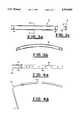
- FIG. 1is a perspective view of a number of implanted prosthetic ribs of applicant's design.
- FIG. 2ais an elevational view of the prosthetic rib of Applicant's invention in a contracted configuration rib sleeve being shown as transparent.
- FIG. 2bis a top plan view of the prosthetic rib of Applicant's invention in a contracted configuration with the rib sleeve being shown as transparent.
- FIG. 2cis an elevational view of the prosthetic rib of Applicant's invention in an extended configuration.
- FIG. 3ais a top plan view of the rib sleeve of Applicant's invention.
- FIG. 3bis an elevational view of the rib sleeve of Applicant's invention.
- FIG. 3cis a cross sectional view of the rib sleeve of Applicant's invention.
- FIG. 4ais a top plan view of the rib shaft/rib shaft carriage attachment of Applicant's invention.
- FIG. 4bis a partial elevational view of the rib shaft/rib shaft carriage attachment of Applicant's invention.
- FIG. 5ais a perspective view of the inner surface of the distraction lock of Applicant's invention.
- FIG. 5bis an elevational view of the inner surface of the distraction lock of Applicant's invention.
- FIG. 5cis a perspective view of the outer surface of the distraction lock of Applicant's invention.
- FIG. 5dis a perspective view of the distraction lock of Applicant's invention placed on a length of the rib sleeve.
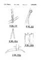
- FIG. 6ais a depiction of the rounded rod of Applicant's invention as it contacts the natural rib of a recipient.
- FIG. 6bis a depiction of the an angular rob, a taught against by Applicant's invention, as it would contact the natural rib of a recipient.
- FIG. 7ais a partial perspective view of the rib sleeve carriage attachment of Applicant's invention.
- FIG. 7bis a partial perspective view of the rib sleeve carriage attachment of Applicant's invention with the rods thereof bent as for initial implantation procedures.
- FIG. 7cis a partial perspective view of Applicant's rib sleeve carriage attachment with the rods thereof encircling a natural rib of a recipient according to the teaching of Applicant's invention.
- FIG. 7dis a cross sectional view of Applicant's rib sleeve carriage attachment with the rods thereof encircling a natural rib of a recipient according to the teaching of Applicant's invention.
- FIGS. 8a and 8bare serial representations of the action of the Applicant's prosthetic rib in absorbing impact.
- FIG. 9ais a perspective representation of a means of attachment not taught by Applicant shown to demonstrate the comparative stability of Applicant's preferred embodiment.
- FIG. 9bis a partial perspective representation of one of Applicant's carriage attachments depicting the stability provided by the dual robs included therein.
- FIG. 10is a partial perspective representation of one of Applicant's carriage attachments depicting the stability provided by the dual rods included therein.
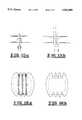
- FIGS. 11a and 11bare elevational representations of one of Applicant's carriage attachments with the rods thereof affixed to the natural rib whereby the prosthetic rib projects perpendicularly from the rib surface.
- FIGS. 11c and 11dare elevational representations of one of Applicant's carriage attachments with the rods thereof affixed to the natural rib whereby the prosthetic rib projects obliquely from the rib surface.
- FIG. 13is a representation of the manipulation of the rods of Applicant's carriage attachments which permits inward adjustment of the over-all prosthetic rib.
- FIG. 14ais a representation of the pliers used to adjust the length of an implanted prosthetic rib.
- FIG. 14bis a representation of the tips of the pliers shown in FIG. 14a.
- FIG. 14cis a representation of the pliers of FIG. 14a is position to adjust the rib shaft relative to the rib sleeve.
- FIG. 15ais a representation of rods improperly spaced on a recipient natural rib.
- FIG. 15bis a representation of rods properly spaced on a recipient natural rib.
- FIG. 16ais a representation of an implanted sheet of medical elastomeric plastic material underlying Applicant's prosthetic ribs.
- FIG. 16bis a representation of the sheet of medical elastomeric plastic material of FIG. 16a.
- the prosthetic rib of Applicant's inventionis identified generally by the reference numeral 10.
- multiple prosthetic ribs 10will typically be implanted to span between existing natural ribs 12 to compensate for an abnormal absence of intervening natural ribs.
- the prosthetic rib 10is designed to be adjusted in length subsequent to implantation.
- the primary purpose of the adjustabilitybeing to accommodate growth of a child in whom the prosthetic rib 10 is implanted.
- the prosthetic rib 10comprises three principal components: a rib sleeve carriage attachment 14, a rib shaft/rib shaft carriage attachment 16 and a rib sleeve 18.
- the rib shaft/rib shaft carriage attachment 16is a single object of unitary construction, but for discussion purposes may be divided between the rib shaft 16a and the rib shaft carriage attachment 16b.
- all components of the prosthetic rib 10, except the rib sleeve 18, which is made of Titanium Alloy 64,are manufactured of Commercially Pure (CP) Titanium.
- CPCommercially Pure
- the use of titaniumis dictated by the strength and flexibility requirements for the components of the prosthetic rib 10 in light of the dimensions of such components.
- Other materials, such as surgical grade stainless steel,may be used in constructing the prosthetic rib 10, but at the expense of the optimum balance of benefits derived from titanium.
- the combined rib shaft 16a and rib sleeve 18serve as the actual prosthesis.
- the robs 20 of the carriage attachments 14 and 16bserve as the attachment means for anchoring the prosthetic rib 10 to natural ribs 12 and will be discussed in detail hereinafter.
- the rib sleeve 18may be described as an open, semi-oval with a lengthwise oriented channel 22 interrupting the lower surface of the rib sleeve 18.
- the presence of the channel 22is in response to manufacturing cost limitations. It should be understood that a suitable alternative sleeve which lacks the channel 22 entirely (not shown in the drawings) would be acceptable for the purposes stated herein, but would be available, if at all, at a considerably higher price because of difficulties in manufacturing such a sleeve.
- the rib shaft 16a and the rib sleeve 18are formed whereby they jointly define a single arc having a constant radius of curvature regardless of the degree the rib shaft 16a is received within the rib sleeve 18.
- the rib sleeve's 18 and rib shaft's 16a radius of curvaturemay be adjusted in the manufacturing process according to the expressed preference of the responsible surgeon, as dictated by the physiology of the intended recipient.
- the effective length of the prosthetic rib 10is determined by the degree to which the rib shaft 16a is telescopically received within the rib sleeve 18.
- the rib shaft 16ahas a plurality of evenly spaced holes 26 passing therethrough.
- the rib sleeve 18has two holes 28 spaced complementarily to the holes 26 in the rib shaft 16a.
- the holes 28 in the rib sleeve 18are situated on the outer face of the rib sleeve 18.
- the rib sleeve carriage attachment 14also has one hole 30 passing through its sleeve engaging projection 14a.
- the holes 26, 28, and 30are oriented whereby a linear object may concurrently extend through one of holes 26 in the rib shaft 16a and one of the two holes 28 in the rib sleeve 18 when the rib shaft 16a is telescopically received within one end of the rib sleeve 18.
- a second linear objectmay extend through hole 30 in the rib sleeve attachment carriage 14 and through the hole 28 in the rib sleeve 18 when the sleeve projection 14a is telescopically received and properly positioned within the other end of the rib sleeve 18.
- the distraction lock 32includes a pin 34 long enough to extend through either holes 28 and 26 or through holes 28 and 30 when in position on the assembled prosthetic rib 10, but not long enough to extend beyond the termini of the gripper flanges 36.
- the tip of the pin 34 as well as the termini of the gripper flanges 36are rounded.
- the limit on the length of the pin 34 and the just-referenced roundingare in satisfaction of safety concerns. Sharp edges and slender protrusions are to be avoided in anticipation of the distraction lock 32 possibly becoming dislodged after implantation and have been so avoided in Applicant's preferred embodiment of the distraction lock.
- the holes 26have been spaced in 10 mm intervals in anticipation of the likely growth intervals which will indicative an adjustment of the prosthetic rib 10. Such spacing is in recognition of the fact that only slight misalignment of the spinal column can result in discomfort and possible spinal cord injury.
- both the rib sleeve carriage attachment 14 and the rib shaft carriage attachment 16binclude two rods 20 at their respective ends.
- the robs 20are round in cross section.
- the rods 20have a cross sectional diameter of 2 mm in the preferred embodiment.
- the rods' 20 round cross sectional shapewas chosen as a means for minimizing the biological trauma to the periosteum of the ribs 12 and to the inferior surfaces of the ribs 12 where the rods 20 have their primary contact therewith (to be discussed in more detail hereinafter).
- the specific 2 mm diameter of the rods 20was chosen after numerous alternative specifications were tested.
- a 2 mm diameter of CP Titaniumhas proven to provide the optimum balance between the flexibility necessary for safe manipulation during implantation and strength necessary for post-implantation stability. No other material tested in a 2 mm rod configuration and no other dimension in CP Titanium provided the preferred characteristics for the rods 20.
- the rods 20 of the preferred embodimentare 76 mm in length. This length has been shown through experimentation to provide a quite acceptable degree of surplus length to facilitate the needed manipulation during implantation both to circumvent the natural ribs 12 at the basic level, as well as to adjust the orientation and position of the loops formed from the rods 20 in determining the over-all orientation of the prosthetic rib 10 within the patient.
- the indicated lengthdoes not, however, introduce excessive length which would impede maneuvering during implantation and require excessive bending to avoid surrounding tissues.
- the rods 20are during the implantation procedure manipulated by the surgeon to circumvent the appropriate natural rib 12.
- the path of the rods 20 about the natural rib 12is essentially circular when properly implanted, even though the rib would be better described as oblong. This is an important aspect of practicing Applicant's invention for several independently significant reasons.
- the circular circumventionpermits the carriage attachments 14 and 16b to pivot relative to the natural ribs 12. This is important, in part, because the carriage attachments 14 and 16b change orientation relative to the ribs 12 to which they are attached as the length of the prosthetic rib 10 is changed subsequent to implantation.
- the ability of the carriage attachments 14 and 16b to pivotis further important in allowing the prosthetic rib 10 to partially accommodate traumatic force which may occur in falls, etc. while not transferring the force to the natural ribs 12 in a manner which would likely fracture the natural ribs 12. If the carriage attachments 14 and 16b were rigidly attached to natural ribs 12, the carriage attachments 14 and 16b would apply a possibly damaging torque to the natural ribs 12 in response to a traumatic force to the rib shaft 16a and/or rib sleeve 18. This is substantially avoided by the circular path of circumvention suggested herein.
- the relatively loose circumvention of the natural ribs 12obviates the danger of rib ischemica at the site of contact between the rods 20 and the natural rib 12 surface. Still further, the gentle movement permitted by the preferred mode of attachment for the prosthetic rib 10 and brought about by normal movement of the recipient has the tendency to promote work hypertrophy thereby actually strengthening the natural rib 12.
- the rods' 20 principal contact with the natural ribs 12are to inner surface areas of the natural ribs 12 relative to the intervening chest wall defect. In this manner, the rods 20 "cradle" the natural ribs 12 at a point of minimum contact as opposed to deleteriously compressing them.
- the rods 20number two for each of the carriage attachments 14 and 16b in satisfaction of some of Applicant's material objectives in designing the preferred embodiment.
- dual attachment sites for the carriage attachments 14 and 16bas opposed to a singular attachment site, provide substantial rotational stability for the prosthetic rib 20.
- a single site of attachmentwill do little to stabilize the prosthetic rib 10 against even minor deflective forces while a dual attachment quite ably resists such force.
- the cumulative mass of titanium needed for strength of the attachment to the natural ribs 12can be divided between the two rods 20 as opposed to being embodied in a single, larger rod. Such a single rod would be too stiff to safely manipulate during implantation if it incorporated the same quantum of titanium as is divided between the two rods 20 of each carriage attachment 14 and 16b of the preferred embodiment.
- a perhaps less apparent benefit of dual rods 20 with a certain degree of surplus lengthlies in the flexibility provided to the surgeon ni orienting the prosthetic rib 10 relative to the natural ribs 12 to which the prosthetic rib 10 is attached.
- the portions of the ribs 12 to which a prosthetic rib 10 is attachedare seldom precisely perpendicular to the desired lengthwise orientation of the prosthetic rib 10.
- the over-all prosthetic rib 10can be oriented in any desired manner. Particularly where the variance from a perpendicular orientation is notably pronounced, the duel rods 20 cooperate to minimize the chance of slippage along the natural rib 12.
- the surgeonmay not want the prosthetic rib 10 to be oriented with the convexity of the rib shaft 16a and the rib sleeve 18 extending "radially" from the patient.
- the dual rods 20permit appropriate three dimensional alignment of the prosthetic rib 10 without sacrificing stability of its attachment to the natural ribs 12.
- the loops formed from the rods 20may be situated in an eccentric relationship whereby the respective carriage attachment 14 or 16b is directed obliquely relative to the path of the natural rib 12.
- the surgical procedure involved in implantation of the prosthetic ribis outlined as follows:
- the patientis placed in a lateral decubitus position.
- the arm on the side of the procedureis free draped to allow for positioning during surgery.
- a longitudinal, curvi-linear incisionis then made over the area of the chest wall defect and carried down to the level of the defect.
- the skin flapsare then developed proximal and distal and are retracted.
- the natural, vestigial ribs that are present proximal and distal to the chest wall defectare isolated.
- the prosthesis siteis first selected posteriorly.
- the fully assembled prosthetic ribis then vertically positioned in the most posterior position of the chest wall defect, and the two rods extending from each carriage attachment are placed overlying the natural ribs and the sites are marked with a cutting cautery.
- the prosthetic ribis then removed and a clamp is used to pierce the intercostal muscle overlying the natural rib at each site with the lung safely held away from the camp.
- a clampis used to pierce the intercostal muscle overlying the natural rib at each site with the lung safely held away from the camp.
- two holesare placed over the superior surface of the natural rib where the prosthetic rib will be placed.
- a similar procedureis repeated at the area immediately inferior to the natural, vestigial rib at inferior limit of the chest wall defect.
- the prosthetic ribis replaced over the chest wall defect and the two rods of each carriage attachment are bent toward the chest wall cavity at a near right angle to the length of the assembled rib shaft and rib sleeve.
- the rods of the rib shaft carriage attachmentare inserted partway through the incisions over the superior surface of the superior natural rib.
- the rods of the rib sleeve carriage attachmentare inserted partway through the incisions under the inferior surface of the inferior natural rib.
- the lungis again retracted, the rib sleeve is disengaged from the rib shaft and from the rib sleeve carriage attachment so that both carriage attachments can be rotated so that the respective rods inside the chest cavity are brought out toward the surgeon for visualization in the chest wall defect.
- the rib shaft carriage attachmentsare sequentially held in place as the surgeon, using pliers or a suitable substitute, manipulates the rods to circumvent the natural ribs in a circular, minimally pitched spiral configuration with the most distal portion of each rod coming to closely juxtapose its proximal origin exterior to the chest cavity (See FIG. 15b).
- the only interthoracic portions of the carriage attachmentsare the curved, smooth surfaces of the rods.
- the rib sleeveis re-engaged with the rib shaft and the engaging projection of the rib sleeve carriage attachment to allow final positioning of the prosthetic rib assembly.
- the radius and length of the rodsare adjusted to provide final position of the actual over all prosthetic rib assembly.
- the loops formed of the rodscan be adjusted to lie eccentrically to orient the rib shaft and rib sleeve in an anterior lateral or posterior lateral position.
- a suitable plurality of prosthetic ribsare implanted as just described in an anterior progression until the chest wall defect is adequately overlain.
- the periphery of the silastic sheetis sutured in each corner and, utilizing a zero proline suture, the plastic sheet is attached at two inch intervals along each prosthetic rib to tether it up to the external chest wall formed by the prosthetic ribs. Chest tubes are then inserted inside the thoracic cavity to fully expand the lugs and then the skin surface is closed in the usual surgical manner.
- the patient under general anaesthetichas an incision made in the scar from the original implantation. Once this is done the skin flap is minimally dissected down toward the distraction locks securing the rib shaft relative to the rib sleeve. Once distraction locks are located, they are removed from each of the prosthetic ribs except the central most one. Next, distraction pliers (shown in FIGS. 14a, 14b, and 14c) are engaged with the central most prosthetic rib and the last distraction lock is removed. The distraction pliers are used to lengthen the central most prosthetic rib to the desired extent to expand the affected chest cavity to the length of the normal chest cavity. Once this adjustment is performed, distraction locks are placed on all prosthetic ribs to secure their adjusted lengths and states.
- the silastic sheet's edgesare drawn further to the edges of the actual borders of the chest wall defect and the proline suture which is tethering the silastic sheet to the undersurface of the ribs slides on top of the body of the prosthetic ribs. Once this is accomplished, a radiograph checks their final position and the skin gets closed in the usual fashion. No chest tubes are needed.
Landscapes
- Health & Medical Sciences (AREA)
- Orthopedic Medicine & Surgery (AREA)
- Life Sciences & Earth Sciences (AREA)
- Surgery (AREA)
- General Health & Medical Sciences (AREA)
- Neurology (AREA)
- Veterinary Medicine (AREA)
- Engineering & Computer Science (AREA)
- Biomedical Technology (AREA)
- Heart & Thoracic Surgery (AREA)
- Public Health (AREA)
- Animal Behavior & Ethology (AREA)
- Molecular Biology (AREA)
- Medical Informatics (AREA)
- Nuclear Medicine, Radiotherapy & Molecular Imaging (AREA)
- Cardiology (AREA)
- Oral & Maxillofacial Surgery (AREA)
- Transplantation (AREA)
- Vascular Medicine (AREA)
- Prostheses (AREA)
- Materials For Medical Uses (AREA)
Abstract
Description
Claims (34)
Priority Applications (9)
| Application Number | Priority Date | Filing Date | Title |
|---|---|---|---|
| US07/338,227US5092889A (en) | 1989-04-14 | 1989-04-14 | Expandable vertical prosthetic rib |
| PCT/US1990/002018WO1990012553A1 (en) | 1989-04-14 | 1990-04-13 | Expandable vertical prosthetic rib |
| ES90906652TES2122959T3 (en) | 1989-04-14 | 1990-04-13 | EXTENSIBLE VERTICAL PROSTHETIC RIB. |
| AU55245/90AAU5524590A (en) | 1989-04-14 | 1990-04-13 | Expandable vertical prosthetic rib |
| DE69032527TDE69032527T2 (en) | 1989-04-14 | 1990-04-13 | LENGTH ADJUSTABLE VERTICAL RIB PROSTHESIS |
| EP90906652AEP0530177B1 (en) | 1989-04-14 | 1990-04-13 | Expandable vertical prosthetic rib |
| AT90906652TATE168878T1 (en) | 1989-04-14 | 1990-04-13 | LENGTH-ADJUSTABLE, VERTICAL RIB PROSTHESIS |
| CA002051665ACA2051665C (en) | 1989-04-14 | 1990-04-13 | Expandable vertical prosthetic rib |
| US07/768,742US5261908A (en) | 1989-04-14 | 1990-04-14 | Expandable vertical prosthetic rib |
Applications Claiming Priority (1)
| Application Number | Priority Date | Filing Date | Title |
|---|---|---|---|
| US07/338,227US5092889A (en) | 1989-04-14 | 1989-04-14 | Expandable vertical prosthetic rib |
Related Child Applications (1)
| Application Number | Title | Priority Date | Filing Date |
|---|---|---|---|
| US07/768,742Continuation-In-PartUS5261908A (en) | 1989-04-14 | 1990-04-14 | Expandable vertical prosthetic rib |
Publications (1)
| Publication Number | Publication Date |
|---|---|
| US5092889Atrue US5092889A (en) | 1992-03-03 |
Family
ID=23323951
Family Applications (2)
| Application Number | Title | Priority Date | Filing Date |
|---|---|---|---|
| US07/338,227Expired - LifetimeUS5092889A (en) | 1989-04-14 | 1989-04-14 | Expandable vertical prosthetic rib |
| US07/768,742Expired - LifetimeUS5261908A (en) | 1989-04-14 | 1990-04-14 | Expandable vertical prosthetic rib |
Family Applications After (1)
| Application Number | Title | Priority Date | Filing Date |
|---|---|---|---|
| US07/768,742Expired - LifetimeUS5261908A (en) | 1989-04-14 | 1990-04-14 | Expandable vertical prosthetic rib |
Country Status (8)
| Country | Link |
|---|---|
| US (2) | US5092889A (en) |
| EP (1) | EP0530177B1 (en) |
| AT (1) | ATE168878T1 (en) |
| AU (1) | AU5524590A (en) |
| CA (1) | CA2051665C (en) |
| DE (1) | DE69032527T2 (en) |
| ES (1) | ES2122959T3 (en) |
| WO (1) | WO1990012553A1 (en) |
Cited By (82)
| Publication number | Priority date | Publication date | Assignee | Title |
|---|---|---|---|---|
| US5261908A (en)* | 1989-04-14 | 1993-11-16 | Campbell Robert M Jr | Expandable vertical prosthetic rib |
| WO1993022989A1 (en)* | 1992-05-19 | 1993-11-25 | Campbell Robert M Jr | Treatment of thoracic deformities such as scoliosis |
| US5476465A (en)* | 1993-04-21 | 1995-12-19 | Amei Technologies Inc. | Surgical cable crimp |
| US5749873A (en)* | 1993-11-26 | 1998-05-12 | Fairley; Jeffrey D. | Apparatus for the mobile fixation of bones |
| US5769898A (en)* | 1993-12-09 | 1998-06-23 | Nobel Biocare Ab | Device for supporting a membrane used for promoting bone growth |
| US20020143339A1 (en)* | 2001-02-12 | 2002-10-03 | Medoff Robert J. | Implant device for applying compression across a fracture site |
| US20020183841A1 (en)* | 2001-03-23 | 2002-12-05 | Cohn William E. | Method and apparatus for reducing mitral regurgitation |
| US20020183837A1 (en)* | 2001-03-05 | 2002-12-05 | Streeter Richard B. | Apparatus and method for reducing mitral regurgitation |
| US20020183836A1 (en)* | 2001-02-05 | 2002-12-05 | Liddicoat John R. | Apparatus and method for reducing mitral regurgitation |
| US20030078654A1 (en)* | 2001-08-14 | 2003-04-24 | Taylor Daniel C. | Method and apparatus for improving mitral valve function |
| US20030130730A1 (en)* | 2001-10-26 | 2003-07-10 | Cohn William E. | Method and apparatus for reducing mitral regurgitation |
| US6656221B2 (en) | 2001-02-05 | 2003-12-02 | Viacor, Inc. | Method and apparatus for improving mitral valve function |
| US20040073302A1 (en)* | 2002-02-05 | 2004-04-15 | Jonathan Rourke | Method and apparatus for improving mitral valve function |
| US20050070998A1 (en)* | 2003-05-27 | 2005-03-31 | Rourke Jonathan M. | Method and apparatus for improving mitral valve function |
| US20050277939A1 (en)* | 2004-05-27 | 2005-12-15 | Miller Archibald S Iii | Surgical device for capturing, positioning and aligning portions of a horizontally severed human sternum |
| US20060009767A1 (en)* | 2004-07-02 | 2006-01-12 | Kiester P D | Expandable rod system to treat scoliosis and method of using the same |
| US20060136053A1 (en)* | 2003-05-27 | 2006-06-22 | Rourke Jonathan M | Method and apparatus for improving mitral valve function |
| US20060189992A1 (en)* | 2001-02-12 | 2006-08-24 | Medoff Robert J | Implant device for applying compression across a fracture site |
| US7186264B2 (en) | 2001-03-29 | 2007-03-06 | Viacor, Inc. | Method and apparatus for improving mitral valve function |
| US20070213727A1 (en)* | 2006-02-09 | 2007-09-13 | Apex Abc, Llc | Method and apparatus for bone fracture fixation |
| US20070270803A1 (en)* | 2006-04-06 | 2007-11-22 | Lukas Giger | Remotely Adjustable Tissue Displacement Device |
| US20080082101A1 (en)* | 2006-09-08 | 2008-04-03 | Erhard Reisberg | Implant, implant system, and use of an implant and implant system |
| US20080086115A1 (en)* | 2006-09-07 | 2008-04-10 | Warsaw Orthopedic, Inc. | Intercostal spacer device and method for use in correcting a spinal deformity |
| US20080306505A1 (en)* | 2007-06-05 | 2008-12-11 | Manders Ernest K | Dimensionally Adjustable Soft Tissue Expander |
| US20090112262A1 (en)* | 2007-10-30 | 2009-04-30 | Scott Pool | Skeletal manipulation system |
| US20090248079A1 (en)* | 2008-03-26 | 2009-10-01 | Kwak Seungkyu Daniel | S-Shaped Interspinous Process Spacer Having Tight Access Offset Hooks |
| US20090248076A1 (en)* | 2008-03-26 | 2009-10-01 | Reynolds Martin A | Interspinous Process Spacer Having Tight Access Offset Hooks |
| US20090275987A1 (en)* | 2008-05-02 | 2009-11-05 | Thomas James Graham | Bone plate extender and extension system for bone restoration and methods of use thereof |
| US20090275947A1 (en)* | 2008-05-02 | 2009-11-05 | Thomas James Graham | Bone plate system for bone restoration and methods of use thereof |
| US20090281577A1 (en)* | 2008-05-08 | 2009-11-12 | Thomas James Graham | Bone plate with reduction aids and methods of use thereof |
| US20100049252A1 (en)* | 2008-08-21 | 2010-02-25 | Southern Spine, Llc | Transverse Connector Device for Extending an Existing Spinal Fixation System |
| US20100094302A1 (en)* | 2008-10-13 | 2010-04-15 | Scott Pool | Spinal distraction system |
| US20100137913A1 (en)* | 2008-11-03 | 2010-06-03 | Roberto Khatchadourian | Adjustable rod assembly |
| US20100217271A1 (en)* | 2009-02-23 | 2010-08-26 | Ellipse Technologies, Inc. | Spinal distraction system |
| US20110106081A1 (en)* | 2008-05-08 | 2011-05-05 | Thomas James Graham | Bone Plate with Flange Member and Methods of Use Thereof |
| US7981025B2 (en) | 2006-10-20 | 2011-07-19 | Ellipse Technologies, Inc. | Adjustable implant and method of use |
| US20110208243A1 (en)* | 2010-02-25 | 2011-08-25 | Christopher Ramsay | Crossover spinous process implant |
| US8382756B2 (en) | 2008-11-10 | 2013-02-26 | Ellipse Technologies, Inc. | External adjustment device for distraction device |
| US20140163691A1 (en)* | 2011-05-23 | 2014-06-12 | Philippe Dartevelle | Osteosynthesis implant |
| US20140222074A1 (en)* | 2013-02-01 | 2014-08-07 | DePuy Synthes Products, LLC | Bone support apparatus |
| US8894663B2 (en) | 2006-04-06 | 2014-11-25 | DePuy Synthes Products, LLC | Remotely adjustable tissue displacement device |
| US9248043B2 (en) | 2010-06-30 | 2016-02-02 | Ellipse Technologies, Inc. | External adjustment device for distraction device |
| CN107456298A (en)* | 2017-09-29 | 2017-12-12 | 大连派思益科技有限公司 | The attachment structure of Artificial Rib |
| US9907580B2 (en) | 2005-11-22 | 2018-03-06 | Bryson Medical Technology Llc | Adjustable spinous process spacer device and method of treating spinal disorders |
| CN108056844A (en)* | 2017-12-26 | 2018-05-22 | 云南大学 | A kind of multisection type 3D printing Artificial Rib with retractable structure |
| US10016220B2 (en) | 2011-11-01 | 2018-07-10 | Nuvasive Specialized Orthopedics, Inc. | Adjustable magnetic devices and methods of using same |
| US10206719B2 (en) | 2016-12-16 | 2019-02-19 | Nuvasive, Inc. | Bone hook apparatus |
| US10238427B2 (en) | 2015-02-19 | 2019-03-26 | Nuvasive Specialized Orthopedics, Inc. | Systems and methods for vertebral adjustment |
| US10271885B2 (en) | 2014-12-26 | 2019-04-30 | Nuvasive Specialized Orthopedics, Inc. | Systems and methods for distraction |
| US10405891B2 (en) | 2010-08-09 | 2019-09-10 | Nuvasive Specialized Orthopedics, Inc. | Maintenance feature in magnetic implant |
| CN110366391A (en)* | 2017-03-08 | 2019-10-22 | 捷迈拜欧米特Cmf和胸腔有限公司 | Chest bar support device |
| US10478232B2 (en) | 2009-04-29 | 2019-11-19 | Nuvasive Specialized Orthopedics, Inc. | Interspinous process device and method |
| US10617453B2 (en) | 2015-10-16 | 2020-04-14 | Nuvasive Specialized Orthopedics, Inc. | Adjustable devices for treating arthritis of the knee |
| US10646262B2 (en) | 2011-02-14 | 2020-05-12 | Nuvasive Specialized Orthopedics, Inc. | System and method for altering rotational alignment of bone sections |
| US20200187993A1 (en)* | 2018-12-18 | 2020-06-18 | Frank J. Schwab | Technologies for lines coupled to spines |
| US10743794B2 (en) | 2011-10-04 | 2020-08-18 | Nuvasive Specialized Orthopedics, Inc. | Devices and methods for non-invasive implant length sensing |
| US10751094B2 (en) | 2013-10-10 | 2020-08-25 | Nuvasive Specialized Orthopedics, Inc. | Adjustable spinal implant |
| US10835292B2 (en) | 2018-06-13 | 2020-11-17 | Nuvasive, Inc. | Rib fixation device and related methods |
| US10835290B2 (en) | 2015-12-10 | 2020-11-17 | Nuvasive Specialized Orthopedics, Inc. | External adjustment device for distraction device |
| US10918425B2 (en) | 2016-01-28 | 2021-02-16 | Nuvasive Specialized Orthopedics, Inc. | System and methods for bone transport |
| US11191579B2 (en) | 2012-10-29 | 2021-12-07 | Nuvasive Specialized Orthopedics, Inc. | Adjustable devices for treating arthritis of the knee |
| US11202707B2 (en) | 2008-03-25 | 2021-12-21 | Nuvasive Specialized Orthopedics, Inc. | Adjustable implant system |
| US11207110B2 (en) | 2009-09-04 | 2021-12-28 | Nuvasive Specialized Orthopedics, Inc. | Bone growth device and method |
| US11241257B2 (en) | 2008-10-13 | 2022-02-08 | Nuvasive Specialized Orthopedics, Inc. | Spinal distraction system |
| US11246694B2 (en) | 2014-04-28 | 2022-02-15 | Nuvasive Specialized Orthopedics, Inc. | System for informational magnetic feedback in adjustable implants |
| USRE49061E1 (en) | 2012-10-18 | 2022-05-10 | Nuvasive Specialized Orthopedics, Inc. | Intramedullary implants for replacing lost bone |
| US11357547B2 (en) | 2014-10-23 | 2022-06-14 | Nuvasive Specialized Orthopedics Inc. | Remotely adjustable interactive bone reshaping implant |
| US11432858B2 (en) | 2017-02-10 | 2022-09-06 | Zimmer Biomet CMF and Thoracic, LLC | Stabilizer holder and inserter tool and methods |
| US11577097B2 (en) | 2019-02-07 | 2023-02-14 | Nuvasive Specialized Orthopedics, Inc. | Ultrasonic communication in medical devices |
| US11589901B2 (en) | 2019-02-08 | 2023-02-28 | Nuvasive Specialized Orthopedics, Inc. | External adjustment device |
| US11696836B2 (en) | 2013-08-09 | 2023-07-11 | Nuvasive, Inc. | Lordotic expandable interbody implant |
| USD996615S1 (en) | 2019-01-09 | 2023-08-22 | Mavrek Medical, Llc | Sternal closure device with dual locking mechanism |
| US11737787B1 (en) | 2021-05-27 | 2023-08-29 | Nuvasive, Inc. | Bone elongating devices and methods of use |
| US11766252B2 (en) | 2013-07-31 | 2023-09-26 | Nuvasive Specialized Orthopedics, Inc. | Noninvasively adjustable suture anchors |
| US11801187B2 (en) | 2016-02-10 | 2023-10-31 | Nuvasive Specialized Orthopedics, Inc. | Systems and methods for controlling multiple surgical variables |
| US11806054B2 (en) | 2021-02-23 | 2023-11-07 | Nuvasive Specialized Orthopedics, Inc. | Adjustable implant, system and methods |
| US11839410B2 (en) | 2012-06-15 | 2023-12-12 | Nuvasive Inc. | Magnetic implants with improved anatomical compatibility |
| US11857226B2 (en) | 2013-03-08 | 2024-01-02 | Nuvasive Specialized Orthopedics | Systems and methods for ultrasonic detection of device distraction |
| US12023073B2 (en) | 2021-08-03 | 2024-07-02 | Nuvasive Specialized Orthopedics, Inc. | Adjustable implant |
| US20240299070A1 (en)* | 2023-03-06 | 2024-09-12 | Zimmer Biomet CMF and Thoracic, LLC | Pectus bar and stabilizer devices and methods |
| US12213708B2 (en) | 2020-09-08 | 2025-02-04 | Nuvasive Specialized Orthopedics, Inc. | Remote control module for adjustable implants |
| US12310629B2 (en) | 2021-02-10 | 2025-05-27 | Alphatec Spine, Inc. | Methods and devices for augmenting the spine |
Families Citing this family (96)
| Publication number | Priority date | Publication date | Assignee | Title |
|---|---|---|---|---|
| FR2659225B1 (en)* | 1990-03-08 | 1995-09-08 | Sofamor | TRANSVERSE FIXING DEVICE FOR PROVIDING A RIGID CROSS-LINK BETWEEN TWO RODS OF A SPINAL OSTEOSYNTHESIS SYSTEM. |
| AU4630393A (en)* | 1992-06-08 | 1994-01-04 | Robert M. Campbell Jr. | Segmental rib carriage instrumentation and associated methods |
| US5611354A (en) | 1992-11-12 | 1997-03-18 | Alleyne; Neville | Cardiac protection device |
| ATE206602T1 (en)* | 1992-11-12 | 2001-10-15 | Neville Alleyne | DEVICE FOR PROTECTING THE HEART |
| US6299613B1 (en)* | 1999-04-23 | 2001-10-09 | Sdgi Holdings, Inc. | Method for the correction of spinal deformities through vertebral body tethering without fusion |
| DE10021382A1 (en)* | 2000-05-03 | 2001-11-08 | Takata Europ Gmbh | Seatbelt device for vehicle; has belt held on belt roller tensioned by spiral spring, with device to prevent belt from unrolling and belt guide device over passenger's shoulder to guide belt |
| FR2827498B1 (en) | 2001-07-18 | 2004-05-14 | Frederic Fortin | FLEXIBLE VERTEBRAL CONNECTION DEVICE CONSISTING OF PALLIANT ELEMENTS OF THE RACHIS |
| SK1002004A3 (en)* | 2001-08-20 | 2004-08-03 | Synthes Ag | Interspinal prosthesis |
| FR2843538B1 (en) | 2002-08-13 | 2005-08-12 | Frederic Fortin | DEVICE FOR DISTRACTING AND DAMPING ADJUSTABLE TO THE GROWTH OF THE RACHIS |
| US6918910B2 (en) | 2002-12-16 | 2005-07-19 | John T. Smith | Implantable distraction device |
| US7635365B2 (en) | 2003-08-28 | 2009-12-22 | Ellis Thomas J | Bone plates |
| GB2435429B (en)* | 2003-08-28 | 2008-03-26 | Univ Oregon Health & Science | Bone plates |
| US7137985B2 (en) | 2003-09-24 | 2006-11-21 | N Spine, Inc. | Marking and guidance method and system for flexible fixation of a spine |
| US8979900B2 (en) | 2003-09-24 | 2015-03-17 | DePuy Synthes Products, LLC | Spinal stabilization device |
| US20050177155A1 (en)* | 2003-10-28 | 2005-08-11 | Neville Alleyne | Anterior adhesion resistant barrier for spine |
| FR2872020B1 (en) | 2004-06-29 | 2006-12-15 | Frederic Fortin | SCOLIOTIC AUTOCORRECTION DEVICE REQUIRING MORE INTERVENTIONS AFTER IMPLANTATION |
| US8303604B2 (en) | 2004-11-05 | 2012-11-06 | Biomet Sports Medicine, Llc | Soft tissue repair device and method |
| US7909851B2 (en) | 2006-02-03 | 2011-03-22 | Biomet Sports Medicine, Llc | Soft tissue repair device and associated methods |
| US8128658B2 (en) | 2004-11-05 | 2012-03-06 | Biomet Sports Medicine, Llc | Method and apparatus for coupling soft tissue to bone |
| US9017381B2 (en) | 2007-04-10 | 2015-04-28 | Biomet Sports Medicine, Llc | Adjustable knotless loops |
| US7749250B2 (en) | 2006-02-03 | 2010-07-06 | Biomet Sports Medicine, Llc | Soft tissue repair assembly and associated method |
| US8298262B2 (en) | 2006-02-03 | 2012-10-30 | Biomet Sports Medicine, Llc | Method for tissue fixation |
| US8840645B2 (en) | 2004-11-05 | 2014-09-23 | Biomet Sports Medicine, Llc | Method and apparatus for coupling soft tissue to a bone |
| US9801708B2 (en) | 2004-11-05 | 2017-10-31 | Biomet Sports Medicine, Llc | Method and apparatus for coupling soft tissue to a bone |
| US8137382B2 (en) | 2004-11-05 | 2012-03-20 | Biomet Sports Medicine, Llc | Method and apparatus for coupling anatomical features |
| US7658751B2 (en) | 2006-09-29 | 2010-02-09 | Biomet Sports Medicine, Llc | Method for implanting soft tissue |
| US7857830B2 (en) | 2006-02-03 | 2010-12-28 | Biomet Sports Medicine, Llc | Soft tissue repair and conduit device |
| US8118836B2 (en) | 2004-11-05 | 2012-02-21 | Biomet Sports Medicine, Llc | Method and apparatus for coupling soft tissue to a bone |
| US7905904B2 (en) | 2006-02-03 | 2011-03-15 | Biomet Sports Medicine, Llc | Soft tissue repair device and associated methods |
| US8361113B2 (en) | 2006-02-03 | 2013-01-29 | Biomet Sports Medicine, Llc | Method and apparatus for coupling soft tissue to a bone |
| US8088130B2 (en) | 2006-02-03 | 2012-01-03 | Biomet Sports Medicine, Llc | Method and apparatus for coupling soft tissue to a bone |
| US8998949B2 (en) | 2004-11-09 | 2015-04-07 | Biomet Sports Medicine, Llc | Soft tissue conduit device |
| ES2318917B1 (en)* | 2005-03-30 | 2010-02-04 | Sdgi Holdings Inc. | SYSTEM FOR THE THREE-DIMENSIONAL CORRECTION OF THE CURVATURE OF THE VERTEBRAL COLUMN IN PROBLEMS OF SCHOLIOSIS BY COPLANAR ALIGNMENT OF THE PEDICULAR SCREWS. |
| US20060241757A1 (en)* | 2005-03-31 | 2006-10-26 | Sdgi Holdings, Inc. | Intervertebral prosthetic device for spinal stabilization and method of manufacturing same |
| US8652172B2 (en) | 2006-02-03 | 2014-02-18 | Biomet Sports Medicine, Llc | Flexible anchors for tissue fixation |
| US10517587B2 (en) | 2006-02-03 | 2019-12-31 | Biomet Sports Medicine, Llc | Method and apparatus for forming a self-locking adjustable loop |
| US8574235B2 (en) | 2006-02-03 | 2013-11-05 | Biomet Sports Medicine, Llc | Method for trochanteric reattachment |
| US8562645B2 (en) | 2006-09-29 | 2013-10-22 | Biomet Sports Medicine, Llc | Method and apparatus for forming a self-locking adjustable loop |
| US8652171B2 (en) | 2006-02-03 | 2014-02-18 | Biomet Sports Medicine, Llc | Method and apparatus for soft tissue fixation |
| US8597327B2 (en) | 2006-02-03 | 2013-12-03 | Biomet Manufacturing, Llc | Method and apparatus for sternal closure |
| US9271713B2 (en) | 2006-02-03 | 2016-03-01 | Biomet Sports Medicine, Llc | Method and apparatus for tensioning a suture |
| US11311287B2 (en) | 2006-02-03 | 2022-04-26 | Biomet Sports Medicine, Llc | Method for tissue fixation |
| US9538998B2 (en) | 2006-02-03 | 2017-01-10 | Biomet Sports Medicine, Llc | Method and apparatus for fracture fixation |
| US8801783B2 (en) | 2006-09-29 | 2014-08-12 | Biomet Sports Medicine, Llc | Prosthetic ligament system for knee joint |
| US8562647B2 (en) | 2006-09-29 | 2013-10-22 | Biomet Sports Medicine, Llc | Method and apparatus for securing soft tissue to bone |
| US8771352B2 (en) | 2011-05-17 | 2014-07-08 | Biomet Sports Medicine, Llc | Method and apparatus for tibial fixation of an ACL graft |
| US8968364B2 (en) | 2006-02-03 | 2015-03-03 | Biomet Sports Medicine, Llc | Method and apparatus for fixation of an ACL graft |
| US8506597B2 (en) | 2011-10-25 | 2013-08-13 | Biomet Sports Medicine, Llc | Method and apparatus for interosseous membrane reconstruction |
| US9149267B2 (en) | 2006-02-03 | 2015-10-06 | Biomet Sports Medicine, Llc | Method and apparatus for coupling soft tissue to a bone |
| US11259792B2 (en) | 2006-02-03 | 2022-03-01 | Biomet Sports Medicine, Llc | Method and apparatus for coupling anatomical features |
| US9468433B2 (en) | 2006-02-03 | 2016-10-18 | Biomet Sports Medicine, Llc | Method and apparatus for forming a self-locking adjustable loop |
| US8251998B2 (en) | 2006-08-16 | 2012-08-28 | Biomet Sports Medicine, Llc | Chondral defect repair |
| US9078644B2 (en) | 2006-09-29 | 2015-07-14 | Biomet Sports Medicine, Llc | Fracture fixation device |
| CA2661444C (en)* | 2006-08-15 | 2015-12-29 | Swissmedtechsolutions Ag | Trochanter retention plate |
| US11259794B2 (en) | 2006-09-29 | 2022-03-01 | Biomet Sports Medicine, Llc | Method for implanting soft tissue |
| US8672969B2 (en) | 2006-09-29 | 2014-03-18 | Biomet Sports Medicine, Llc | Fracture fixation device |
| US8500818B2 (en) | 2006-09-29 | 2013-08-06 | Biomet Manufacturing, Llc | Knee prosthesis assembly with ligament link |
| US9918826B2 (en) | 2006-09-29 | 2018-03-20 | Biomet Sports Medicine, Llc | Scaffold for spring ligament repair |
| US20080269805A1 (en) | 2007-04-25 | 2008-10-30 | Warsaw Orthopedic, Inc. | Methods for correcting spinal deformities |
| US8790380B2 (en)* | 2007-07-26 | 2014-07-29 | Dynamic Spine, Llc | Segmental orthopaedic device for spinal elongation and for treatment of scoliosis |
| US9204908B2 (en)* | 2007-07-26 | 2015-12-08 | Dynamic Spine, Llc | Segmental orthopedic device for spinal elongation and for treatment of scoliosis |
| BRPI0706247A2 (en)* | 2007-09-21 | 2009-12-01 | Cavali Paulo Tadeu Maia | flexible, sliding and dynamic implant system for selective stabilization and correction of spinal deformities and instabilities |
| US12245759B2 (en) | 2008-08-22 | 2025-03-11 | Biomet Sports Medicine, Llc | Method and apparatus for coupling soft tissue to bone |
| US12419632B2 (en) | 2008-08-22 | 2025-09-23 | Biomet Sports Medicine, Llc | Method and apparatus for coupling anatomical features |
| US9237910B2 (en) | 2012-01-26 | 2016-01-19 | Acute Innovations Llc | Clip for rib stabilization |
| US12285197B2 (en) | 2008-10-10 | 2025-04-29 | Acumed Llc | Bone fixation system with opposed mounting portions |
| WO2010078029A1 (en) | 2008-12-17 | 2010-07-08 | Synthes Usa, Llc | Posterior spine dynamic stabilizer |
| US8343227B2 (en) | 2009-05-28 | 2013-01-01 | Biomet Manufacturing Corp. | Knee prosthesis assembly with ligament link |
| US12096928B2 (en) | 2009-05-29 | 2024-09-24 | Biomet Sports Medicine, Llc | Method and apparatus for coupling soft tissue to a bone |
| PL217862B1 (en)* | 2009-10-09 | 2014-08-29 | Lfc Spółka Z Ograniczoną Odpowiedzialnością | Off-load-dynamic intervertebral device |
| US8568417B2 (en) | 2009-12-18 | 2013-10-29 | Charles River Engineering Solutions And Technologies, Llc | Articulating tool and methods of using |
| AU2011264818B2 (en) | 2010-06-10 | 2015-06-18 | Globus Medical, Inc. | Low-profile, uniplanar bone screw |
| CN102293680B (en) | 2010-06-24 | 2014-04-16 | 华沙整形外科股份有限公司 | Coplanar straightening system |
| US8870929B2 (en) | 2011-04-13 | 2014-10-28 | Polyvalor, Limited Partnership Valorisation HSJ, Limited Partnership | Surgical devices for the correction of spinal deformities |
| US12329373B2 (en) | 2011-05-02 | 2025-06-17 | Biomet Sports Medicine, Llc | Method and apparatus for soft tissue fixation |
| WO2013049849A2 (en) | 2011-09-30 | 2013-04-04 | Acute Innovations, Llc, An Oregon Limited Liability Company | Bone fixation system with opposed mounting portions |
| US9357991B2 (en) | 2011-11-03 | 2016-06-07 | Biomet Sports Medicine, Llc | Method and apparatus for stitching tendons |
| US9314241B2 (en) | 2011-11-10 | 2016-04-19 | Biomet Sports Medicine, Llc | Apparatus for coupling soft tissue to a bone |
| US9370350B2 (en) | 2011-11-10 | 2016-06-21 | Biomet Sports Medicine, Llc | Apparatus for coupling soft tissue to a bone |
| US9381013B2 (en) | 2011-11-10 | 2016-07-05 | Biomet Sports Medicine, Llc | Method for coupling soft tissue to a bone |
| FR2990343B1 (en)* | 2012-05-11 | 2014-05-16 | Neuro France Implants Nfi | SPOT DEVICE FOR SIDES |
| US9757119B2 (en) | 2013-03-08 | 2017-09-12 | Biomet Sports Medicine, Llc | Visual aid for identifying suture limbs arthroscopically |
| US9918827B2 (en) | 2013-03-14 | 2018-03-20 | Biomet Sports Medicine, Llc | Scaffold for spring ligament repair |
| US9668773B2 (en)* | 2013-03-14 | 2017-06-06 | Globus Medical, Inc. | Spinal implant for use in thoracic insufficiency syndrome |
| US10136886B2 (en) | 2013-12-20 | 2018-11-27 | Biomet Sports Medicine, Llc | Knotless soft tissue devices and techniques |
| US9615822B2 (en) | 2014-05-30 | 2017-04-11 | Biomet Sports Medicine, Llc | Insertion tools and method for soft anchor |
| US9700291B2 (en) | 2014-06-03 | 2017-07-11 | Biomet Sports Medicine, Llc | Capsule retractor |
| US10039543B2 (en) | 2014-08-22 | 2018-08-07 | Biomet Sports Medicine, Llc | Non-sliding soft anchor |
| CN107427318B (en)* | 2015-02-13 | 2020-08-25 | 拜欧米特制造有限责任公司 | Rib Reconstruction Device |
| US9955980B2 (en) | 2015-02-24 | 2018-05-01 | Biomet Sports Medicine, Llc | Anatomic soft tissue repair |
| US9974534B2 (en) | 2015-03-31 | 2018-05-22 | Biomet Sports Medicine, Llc | Suture anchor with soft anchor of electrospun fibers |
| US10395561B2 (en) | 2015-12-07 | 2019-08-27 | Humanetics Innovative Solutions, Inc. | Three-dimensionally printed internal organs for crash test dummy |
| US10733911B2 (en) | 2015-10-14 | 2020-08-04 | Humanetics Innovative Solutions, Inc. | Three-dimensional ribs and method of three-dimensional printing of ribs for crash test dummy |
| ES2678898B1 (en)* | 2017-02-17 | 2019-05-28 | Valverde Javier Aragon | DYNAMIC ANATOMICAL PROTESIS FOR THE RECONSTRUCTION OF THE TORACICA WALL |
| RU2017147158A (en)* | 2017-12-29 | 2019-07-01 | ФЕДЕРАЛЬНОЕ ГОСУДАРСТВЕННОЕ БЮДЖЕТНОЕ УЧРЕЖДЕНИЕ "НАУЧНО-ИССЛЕДОВАТЕЛЬСКИЙ ДЕТСКИЙ ОРТОПЕДИЧЕСКИЙ ИНСТИТУТ ИМЕНИ Г.И. ТУРНЕРА" Министерства здравоохранения Российской Федерации | Device for the correction of congenital deformity of the spine and chest in unilateral violation of the segmentation of the vertebrae of the thoracic spine and synostosis of the ribs in children |
| EP3962380A4 (en)* | 2019-05-01 | 2023-06-07 | Grant D. Hogue | Internal elastic brace for treating scoliosis |
Citations (20)
| Publication number | Priority date | Publication date | Assignee | Title |
|---|---|---|---|---|
| SU286136A1 (en)* | А. М. Ходов, А. И. Васюков , М. Т. Мамонов | |||
| DE156570C (en)* | ||||
| US3426364A (en)* | 1966-08-25 | 1969-02-11 | Colorado State Univ Research F | Prosthetic appliance for replacing one or more natural vertebrae |
| SU313538A3 (en)* | 1968-11-28 | 1971-10-25 | ||
| SU602173A1 (en)* | 1976-06-09 | 1978-04-15 | Manakov Petr M | Vertebral inclinator |
| US4085744A (en)* | 1977-01-31 | 1978-04-25 | David Warren Lewis | Spinal column prostheses orthoses |
| SU610518A1 (en)* | 1977-01-18 | 1978-06-15 | Крымский Государственный Медицинский Институт | Rib surgery device |
| US4096857A (en)* | 1976-01-20 | 1978-06-27 | Messerschmitt-Boelkow-Blohm Gmbh | Telescopically adjustable surgical instrument |
| GB1517161A (en)* | 1975-08-21 | 1978-07-12 | Raghava M | Implant apparatus for repairing bone fractures |
| DE2821678A1 (en)* | 1978-05-12 | 1979-11-22 | Sulzer Ag | IMPLANT THAT CAN BE INSERTED BETWEEN NEIGHBORING Vertebrae |
| US4201215A (en)* | 1977-09-06 | 1980-05-06 | Crossett E S | Apparatus and method for closing a severed sternum |
| US4279248A (en)* | 1979-07-20 | 1981-07-21 | Shlomo Gabbay | Sternum closure device and procedure for using same |
| US4327715A (en)* | 1979-11-13 | 1982-05-04 | Pierre Corvisier | Device for forming costal prostheses |
| US4606335A (en)* | 1984-08-20 | 1986-08-19 | Highland Orthopedic Center | Cerclage wire passer |
| US4611582A (en)* | 1983-12-27 | 1986-09-16 | Wisconsin Alumni Research Foundation | Vertebral clamp |
| US4657550A (en)* | 1984-12-21 | 1987-04-14 | Daher Youssef H | Buttressing device usable in a vertebral prosthesis |
| US4738251A (en)* | 1987-02-20 | 1988-04-19 | Codespi, Corporation | Correcting device for spine pathology |
| DE3729600A1 (en)* | 1987-09-04 | 1989-03-16 | Aesculap Werke Ag | Implant for insertion between the vertebral bodies of the spine |
| US4815453A (en)* | 1983-05-04 | 1989-03-28 | Societe De Fabrication De Materiel Orthopedique (Sofamor) | Device for supporting the rachis |
| EP0322334A1 (en)* | 1987-12-23 | 1989-06-28 | Cremascoli France | Prosthesis implanted between vertebral spinous processes |
Family Cites Families (10)
| Publication number | Priority date | Publication date | Assignee | Title |
|---|---|---|---|---|
| US313538A (en)* | 1885-03-10 | Folding lunch | ||
| US864329A (en)* | 1907-01-22 | 1907-08-27 | William C North | Brake-rod adjuster. |
| US1049398A (en)* | 1912-03-25 | 1913-01-07 | Zachariah E Rice | Door-knob fastener. |
| US2484401A (en)* | 1946-03-05 | 1949-10-11 | William R Coie | Crutch |
| US2662420A (en)* | 1949-11-22 | 1953-12-15 | Thompson Prod Inc | Adjustable tie rod |
| FR1418091A (en)* | 1964-08-21 | 1965-11-19 | Ministerul Sanatatii Si Preved | Apparatus and method for immobilization of the costal flap |
| DE1280528B (en)* | 1966-10-29 | 1968-10-17 | Friedrich Frueh | Adjustable hangers for the support rails of a false ceiling or the like. |
| FR2416683A1 (en)* | 1978-02-10 | 1979-09-07 | Judet Robert | IMPROVEMENTS TO OSTEO-SYNTHESIS DEVICES |
| US5092889A (en)* | 1989-04-14 | 1992-03-03 | Campbell Robert M Jr | Expandable vertical prosthetic rib |
| US5030235A (en)* | 1990-04-20 | 1991-07-09 | Campbell Robert M Jr | Prosthetic first rib |
- 1989
- 1989-04-14USUS07/338,227patent/US5092889A/ennot_activeExpired - Lifetime
- 1990
- 1990-04-13ESES90906652Tpatent/ES2122959T3/ennot_activeExpired - Lifetime
- 1990-04-13WOPCT/US1990/002018patent/WO1990012553A1/enactiveIP Right Grant
- 1990-04-13EPEP90906652Apatent/EP0530177B1/ennot_activeExpired - Lifetime
- 1990-04-13DEDE69032527Tpatent/DE69032527T2/ennot_activeExpired - Lifetime
- 1990-04-13ATAT90906652Tpatent/ATE168878T1/ennot_activeIP Right Cessation
- 1990-04-13AUAU55245/90Apatent/AU5524590A/ennot_activeAbandoned
- 1990-04-13CACA002051665Apatent/CA2051665C/ennot_activeExpired - Lifetime
- 1990-04-14USUS07/768,742patent/US5261908A/ennot_activeExpired - Lifetime
Patent Citations (20)
| Publication number | Priority date | Publication date | Assignee | Title |
|---|---|---|---|---|
| SU286136A1 (en)* | А. М. Ходов, А. И. Васюков , М. Т. Мамонов | |||
| DE156570C (en)* | ||||
| US3426364A (en)* | 1966-08-25 | 1969-02-11 | Colorado State Univ Research F | Prosthetic appliance for replacing one or more natural vertebrae |
| SU313538A3 (en)* | 1968-11-28 | 1971-10-25 | ||
| GB1517161A (en)* | 1975-08-21 | 1978-07-12 | Raghava M | Implant apparatus for repairing bone fractures |
| US4096857A (en)* | 1976-01-20 | 1978-06-27 | Messerschmitt-Boelkow-Blohm Gmbh | Telescopically adjustable surgical instrument |
| SU602173A1 (en)* | 1976-06-09 | 1978-04-15 | Manakov Petr M | Vertebral inclinator |
| SU610518A1 (en)* | 1977-01-18 | 1978-06-15 | Крымский Государственный Медицинский Институт | Rib surgery device |
| US4085744A (en)* | 1977-01-31 | 1978-04-25 | David Warren Lewis | Spinal column prostheses orthoses |
| US4201215A (en)* | 1977-09-06 | 1980-05-06 | Crossett E S | Apparatus and method for closing a severed sternum |
| DE2821678A1 (en)* | 1978-05-12 | 1979-11-22 | Sulzer Ag | IMPLANT THAT CAN BE INSERTED BETWEEN NEIGHBORING Vertebrae |
| US4279248A (en)* | 1979-07-20 | 1981-07-21 | Shlomo Gabbay | Sternum closure device and procedure for using same |
| US4327715A (en)* | 1979-11-13 | 1982-05-04 | Pierre Corvisier | Device for forming costal prostheses |
| US4815453A (en)* | 1983-05-04 | 1989-03-28 | Societe De Fabrication De Materiel Orthopedique (Sofamor) | Device for supporting the rachis |
| US4611582A (en)* | 1983-12-27 | 1986-09-16 | Wisconsin Alumni Research Foundation | Vertebral clamp |
| US4606335A (en)* | 1984-08-20 | 1986-08-19 | Highland Orthopedic Center | Cerclage wire passer |
| US4657550A (en)* | 1984-12-21 | 1987-04-14 | Daher Youssef H | Buttressing device usable in a vertebral prosthesis |
| US4738251A (en)* | 1987-02-20 | 1988-04-19 | Codespi, Corporation | Correcting device for spine pathology |
| DE3729600A1 (en)* | 1987-09-04 | 1989-03-16 | Aesculap Werke Ag | Implant for insertion between the vertebral bodies of the spine |
| EP0322334A1 (en)* | 1987-12-23 | 1989-06-28 | Cremascoli France | Prosthesis implanted between vertebral spinous processes |
Non-Patent Citations (6)
| Title |
|---|
| Cotton, et al, "Prothesis Following Excision of Chest Wall Tumors," Journal of Thoracic Surgery, 1955, p. 45. |
| Cotton, et al, Prothesis Following Excision of Chest Wall Tumors, Journal of Thoracic Surgery, 1955, p. 45.* |
| Heaney, et al, Unusual Problems in Management of Chest Wall Defects, Journal of Thoracic Surgery, 1954, p. 23.* |
| Kinsella, et al, Two Unusual Tumors of the Sternum, Journal of Thoracic Surgery, 1946, p. 640.* |
| Sherman, et al, Chest Wall Stabilization Using Plat Fixation, The Annals of Thoracic Surgery, Oct. 1988, p. 467, et seq.* |
| Singh, et al, A New Prosthesis for Reconstruction of Congenital Flail Chest, British Journal of Surgery, May 1971, vol. 58, p. 366, et seq.* |
Cited By (199)
| Publication number | Priority date | Publication date | Assignee | Title |
|---|---|---|---|---|
| US5261908A (en)* | 1989-04-14 | 1993-11-16 | Campbell Robert M Jr | Expandable vertical prosthetic rib |
| WO1993022989A1 (en)* | 1992-05-19 | 1993-11-25 | Campbell Robert M Jr | Treatment of thoracic deformities such as scoliosis |
| US5476465A (en)* | 1993-04-21 | 1995-12-19 | Amei Technologies Inc. | Surgical cable crimp |
| US5749873A (en)* | 1993-11-26 | 1998-05-12 | Fairley; Jeffrey D. | Apparatus for the mobile fixation of bones |
| US5769898A (en)* | 1993-12-09 | 1998-06-23 | Nobel Biocare Ab | Device for supporting a membrane used for promoting bone growth |
| US20050071000A1 (en)* | 2001-02-05 | 2005-03-31 | Liddicoat John R. | Apparatus and method for reducing mitral regurgitation |
| US20050049679A1 (en)* | 2001-02-05 | 2005-03-03 | Taylor Daniel C. | Method and apparatus for improving mitral valve function |
| US6790231B2 (en) | 2001-02-05 | 2004-09-14 | Viacor, Inc. | Apparatus and method for reducing mitral regurgitation |
| US20020183836A1 (en)* | 2001-02-05 | 2002-12-05 | Liddicoat John R. | Apparatus and method for reducing mitral regurgitation |
| US6656221B2 (en) | 2001-02-05 | 2003-12-02 | Viacor, Inc. | Method and apparatus for improving mitral valve function |
| US20020143339A1 (en)* | 2001-02-12 | 2002-10-03 | Medoff Robert J. | Implant device for applying compression across a fracture site |
| US7811286B2 (en) | 2001-02-12 | 2010-10-12 | Robert J. Medoff | Implant device for applying compression across a fracture site |
| US7037308B2 (en)* | 2001-02-12 | 2006-05-02 | Medoff Robert J | Implant device for applying compression across a fracture site |
| US20060189992A1 (en)* | 2001-02-12 | 2006-08-24 | Medoff Robert J | Implant device for applying compression across a fracture site |
| WO2002096275A3 (en)* | 2001-03-05 | 2003-02-20 | Viacor Inc | Apparatus and method for reducing mitral regurgitation |
| US20020183837A1 (en)* | 2001-03-05 | 2002-12-05 | Streeter Richard B. | Apparatus and method for reducing mitral regurgitation |
| US20020183841A1 (en)* | 2001-03-23 | 2002-12-05 | Cohn William E. | Method and apparatus for reducing mitral regurgitation |
| US6890353B2 (en) | 2001-03-23 | 2005-05-10 | Viacor, Inc. | Method and apparatus for reducing mitral regurgitation |
| US20050267574A1 (en)* | 2001-03-23 | 2005-12-01 | Cohn William E | Method and apparatus for reducing mitral regurgitation |
| US20070213814A1 (en)* | 2001-03-29 | 2007-09-13 | Liddicoat John R | Method and apparatus for improving mitral valve function |
| US7186264B2 (en) | 2001-03-29 | 2007-03-06 | Viacor, Inc. | Method and apparatus for improving mitral valve function |
| US20030078654A1 (en)* | 2001-08-14 | 2003-04-24 | Taylor Daniel C. | Method and apparatus for improving mitral valve function |
| US20030130730A1 (en)* | 2001-10-26 | 2003-07-10 | Cohn William E. | Method and apparatus for reducing mitral regurgitation |
| US7052487B2 (en) | 2001-10-26 | 2006-05-30 | Cohn William E | Method and apparatus for reducing mitral regurgitation |
| US7241310B2 (en) | 2002-01-14 | 2007-07-10 | Taylor Daniel C | Method and apparatus for reducing mitral regurgitation |
| US20040073302A1 (en)* | 2002-02-05 | 2004-04-15 | Jonathan Rourke | Method and apparatus for improving mitral valve function |
| US7125420B2 (en) | 2002-02-05 | 2006-10-24 | Viacor, Inc. | Method and apparatus for improving mitral valve function |
| US20070156235A1 (en)* | 2002-02-05 | 2007-07-05 | Jonathan Rourke | Method and apparatus for improving mitral valve function |
| US20040102839A1 (en)* | 2002-06-26 | 2004-05-27 | Cohn William E. | Method and apparatus for improving mitral valve function |
| US20060136053A1 (en)* | 2003-05-27 | 2006-06-22 | Rourke Jonathan M | Method and apparatus for improving mitral valve function |
| US7179291B2 (en) | 2003-05-27 | 2007-02-20 | Viacor, Inc. | Method and apparatus for improving mitral valve function |
| US20050070998A1 (en)* | 2003-05-27 | 2005-03-31 | Rourke Jonathan M. | Method and apparatus for improving mitral valve function |
| US20070213758A1 (en)* | 2003-05-27 | 2007-09-13 | Rourke Jonathan M | Method and apparatus for improving mitral valve function |
| US20050277939A1 (en)* | 2004-05-27 | 2005-12-15 | Miller Archibald S Iii | Surgical device for capturing, positioning and aligning portions of a horizontally severed human sternum |
| US9011499B1 (en) | 2004-07-02 | 2015-04-21 | Ellipse Technologies, Inc | Expandable rod system to treat scoliosis and method of using the same |
| US20060009767A1 (en)* | 2004-07-02 | 2006-01-12 | Kiester P D | Expandable rod system to treat scoliosis and method of using the same |
| US9398925B2 (en) | 2004-07-02 | 2016-07-26 | Nuvasive Specialized Orthopedics, Inc. | Expandable rod system to treat scoliosis and method of using the same |
| US8852236B2 (en) | 2004-07-02 | 2014-10-07 | Ellipse Technologies, Inc. | Expandable rod system to treat scoliosis and method of using the same |
| US10016221B2 (en) | 2004-07-02 | 2018-07-10 | Nuvasive Specialized Orthopedics, Inc. | Expandable rod system to treat scoliosis and method of using the same |
| US8343192B2 (en) | 2004-07-02 | 2013-01-01 | Ellipse Technologies, Inc. | Expandable rod system to treat scoliosis and method of using the same |
| US20090204154A1 (en)* | 2004-07-02 | 2009-08-13 | Ellipse Technologies, Inc. | expandable rod system to treat scoliosis and method of using the same |
| US7955357B2 (en) | 2004-07-02 | 2011-06-07 | Ellipse Technologies, Inc. | Expandable rod system to treat scoliosis and method of using the same |
| US11357549B2 (en) | 2004-07-02 | 2022-06-14 | Nuvasive Specialized Orthopedics, Inc. | Expandable rod system to treat scoliosis and method of using the same |
| US11712268B2 (en) | 2004-07-02 | 2023-08-01 | Nuvasive Specialized Orthopedics, Inc. | Expandable rod system to treat scoliosis and method of using the same |
| US9907580B2 (en) | 2005-11-22 | 2018-03-06 | Bryson Medical Technology Llc | Adjustable spinous process spacer device and method of treating spinal disorders |
| US8740903B2 (en) | 2006-02-09 | 2014-06-03 | DePuy Synthes Products, LLC | Method and apparatus for bone fracture fixation |
| US20070213727A1 (en)* | 2006-02-09 | 2007-09-13 | Apex Abc, Llc | Method and apparatus for bone fracture fixation |
| US10105130B2 (en) | 2006-04-06 | 2018-10-23 | DePuy Synthes Products, Inc. | Remotely adjustable tissue displacement device |
| US8016837B2 (en)* | 2006-04-06 | 2011-09-13 | Synthes Usa, Llc | Remotely adjustable tissue displacement device |
| US9259243B2 (en) | 2006-04-06 | 2016-02-16 | DePuy Synthes Products, Inc. | Remotely adjustable tissue displacement device |
| US20070270803A1 (en)* | 2006-04-06 | 2007-11-22 | Lukas Giger | Remotely Adjustable Tissue Displacement Device |
| EP2997916A1 (en) | 2006-04-06 | 2016-03-23 | Synthes GmbH | Remotely adjustable tissue displacement device |
| US8894663B2 (en) | 2006-04-06 | 2014-11-25 | DePuy Synthes Products, LLC | Remotely adjustable tissue displacement device |
| US20080086115A1 (en)* | 2006-09-07 | 2008-04-10 | Warsaw Orthopedic, Inc. | Intercostal spacer device and method for use in correcting a spinal deformity |
| US20080082101A1 (en)* | 2006-09-08 | 2008-04-03 | Erhard Reisberg | Implant, implant system, and use of an implant and implant system |
| US8795342B2 (en)* | 2006-09-08 | 2014-08-05 | Erhard Reisberg | Implant, implant system, and use of an implant and implant system |
| US8808163B2 (en) | 2006-10-20 | 2014-08-19 | Ellipse Technologies, Inc. | Adjustable implant and method of use |
| US10039661B2 (en) | 2006-10-20 | 2018-08-07 | Nuvasive Specialized Orthopedics, Inc. | Adjustable implant and method of use |
| US9271857B2 (en) | 2006-10-20 | 2016-03-01 | Ellipse Technologies, Inc. | Adjustable implant and method of use |
| US7981025B2 (en) | 2006-10-20 | 2011-07-19 | Ellipse Technologies, Inc. | Adjustable implant and method of use |
| US9526650B2 (en) | 2006-10-20 | 2016-12-27 | Nuvasive Specialized Orthopedics, Inc. | Adjustable implant and method of use |
| US11672684B2 (en) | 2006-10-20 | 2023-06-13 | Nuvasive Specialized Orthopedics, Inc. | Adjustable implant and method of use |
| US20110237861A1 (en)* | 2006-10-20 | 2011-09-29 | Ellipse Technologies, Inc. | Adjustable implant and method of use |
| US11234849B2 (en) | 2006-10-20 | 2022-02-01 | Nuvasive Specialized Orthopedics, Inc. | Adjustable implant and method of use |
| US8715159B2 (en) | 2006-10-20 | 2014-05-06 | Ellipse Technologies, Inc. | Adjustable implant and method of use |
| US8007532B2 (en)* | 2007-06-05 | 2011-08-30 | Manders Ernest K | Dimensionally adjustable soft tissue expander |
| US20080306505A1 (en)* | 2007-06-05 | 2008-12-11 | Manders Ernest K | Dimensionally Adjustable Soft Tissue Expander |
| US11172972B2 (en) | 2007-10-30 | 2021-11-16 | Nuvasive Specialized Orthopedics, Inc. | Skeletal manipulation method |
| US9271781B2 (en) | 2007-10-30 | 2016-03-01 | Ellipse Technologies, Inc. | Skeletal manipulation method |
| US9179960B2 (en) | 2007-10-30 | 2015-11-10 | Ellipse Technologies, Inc. | Skeletal manipulation method |
| US20090112207A1 (en)* | 2007-10-30 | 2009-04-30 | Blair Walker | Skeletal manipulation method |
| US10349995B2 (en) | 2007-10-30 | 2019-07-16 | Nuvasive Specialized Orthopedics, Inc. | Skeletal manipulation method |
| US8419734B2 (en) | 2007-10-30 | 2013-04-16 | Ellipse Technologies, Inc. | Skeletal manipulation method |
| US11871974B2 (en) | 2007-10-30 | 2024-01-16 | Nuvasive Specialized Orthopedics, Inc. | Skeletal manipulation method |
| US9693813B2 (en) | 2007-10-30 | 2017-07-04 | Nuvasive Specialized Orthopedics, Inc. | Skeletal manipulation method |
| US20090112263A1 (en)* | 2007-10-30 | 2009-04-30 | Scott Pool | Skeletal manipulation system |
| US20090112262A1 (en)* | 2007-10-30 | 2009-04-30 | Scott Pool | Skeletal manipulation system |
| US8057472B2 (en) | 2007-10-30 | 2011-11-15 | Ellipse Technologies, Inc. | Skeletal manipulation method |
| US12076241B2 (en) | 2008-03-25 | 2024-09-03 | Nuvasive Specialized Orthopedics, Inc. | Adjustable implant system |
| US11202707B2 (en) | 2008-03-25 | 2021-12-21 | Nuvasive Specialized Orthopedics, Inc. | Adjustable implant system |
| US8025678B2 (en) | 2008-03-26 | 2011-09-27 | Depuy Spine, Inc. | Interspinous process spacer having tight access offset hooks |
| US20090248076A1 (en)* | 2008-03-26 | 2009-10-01 | Reynolds Martin A | Interspinous Process Spacer Having Tight Access Offset Hooks |
| US8313512B2 (en) | 2008-03-26 | 2012-11-20 | Depuy Spine, Inc. | S-shaped interspinous process spacer having tight access offset hooks |
| US20090248079A1 (en)* | 2008-03-26 | 2009-10-01 | Kwak Seungkyu Daniel | S-Shaped Interspinous Process Spacer Having Tight Access Offset Hooks |
| US20090275987A1 (en)* | 2008-05-02 | 2009-11-05 | Thomas James Graham | Bone plate extender and extension system for bone restoration and methods of use thereof |
| US8915918B2 (en) | 2008-05-02 | 2014-12-23 | Thomas James Graham | Bone plate system for bone restoration and methods of use thereof |
| US8652179B2 (en) | 2008-05-02 | 2014-02-18 | The Cleveland Clinic Foundation | Bone plate extender and extension system for bone restoration and methods of use thereof |
| US20090275947A1 (en)* | 2008-05-02 | 2009-11-05 | Thomas James Graham | Bone plate system for bone restoration and methods of use thereof |
| US20110106081A1 (en)* | 2008-05-08 | 2011-05-05 | Thomas James Graham | Bone Plate with Flange Member and Methods of Use Thereof |
| US8628533B2 (en) | 2008-05-08 | 2014-01-14 | The Cleveland Clinic Foundation | Bone plate with reduction aids and methods of use thereof |
| US8608783B2 (en) | 2008-05-08 | 2013-12-17 | The Cleveland Clinic Foundation | Bone plate with flange member and methods of use thereof |
| US20090281577A1 (en)* | 2008-05-08 | 2009-11-12 | Thomas James Graham | Bone plate with reduction aids and methods of use thereof |
| US20100049252A1 (en)* | 2008-08-21 | 2010-02-25 | Southern Spine, Llc | Transverse Connector Device for Extending an Existing Spinal Fixation System |
| US20100094302A1 (en)* | 2008-10-13 | 2010-04-15 | Scott Pool | Spinal distraction system |
| US20100094306A1 (en)* | 2008-10-13 | 2010-04-15 | Arvin Chang | Spinal distraction system |
| US11925389B2 (en) | 2008-10-13 | 2024-03-12 | Nuvasive Specialized Orthopedics, Inc. | Spinal distraction system |
| US20100094304A1 (en)* | 2008-10-13 | 2010-04-15 | Scott Pool | Spinal distraction system |
| US20100094303A1 (en)* | 2008-10-13 | 2010-04-15 | Arvin Chang | Spinal distraction system |
| US11241257B2 (en) | 2008-10-13 | 2022-02-08 | Nuvasive Specialized Orthopedics, Inc. | Spinal distraction system |
| US20100094305A1 (en)* | 2008-10-13 | 2010-04-15 | Arvin Chang | Spinal distraction system |
| US8956392B2 (en) | 2008-11-03 | 2015-02-17 | DePuy Synthes Products, LLC | Adjustable rod assembly |
| US10010352B2 (en) | 2008-11-03 | 2018-07-03 | DePuy Synthes Products, Inc. | Adjustable rod assembly |
| DE202009018581U1 (en) | 2008-11-03 | 2012-03-02 | Synthes Gmbh | Adjustable bar arrangement |
| US20100137913A1 (en)* | 2008-11-03 | 2010-06-03 | Roberto Khatchadourian | Adjustable rod assembly |
| US9526524B2 (en) | 2008-11-03 | 2016-12-27 | DePuy Synthes Products, Inc. | Adjustable rod assembly |
| US8974500B2 (en)* | 2008-11-03 | 2015-03-10 | DePuy Synthes Products, LLC | Adjustable rod assembly |
| US10729470B2 (en) | 2008-11-10 | 2020-08-04 | Nuvasive Specialized Orthopedics, Inc. | External adjustment device for distraction device |
| US11974782B2 (en) | 2008-11-10 | 2024-05-07 | Nuvasive Specialized Orthopedics, Inc. | External adjustment device for distraction device |
| US8382756B2 (en) | 2008-11-10 | 2013-02-26 | Ellipse Technologies, Inc. | External adjustment device for distraction device |
| US11918254B2 (en) | 2009-02-23 | 2024-03-05 | Nuvasive Specialized Orthopedics Inc. | Adjustable implant system |
| US20100217271A1 (en)* | 2009-02-23 | 2010-08-26 | Ellipse Technologies, Inc. | Spinal distraction system |
| US11304729B2 (en) | 2009-02-23 | 2022-04-19 | Nuvasive Specialized Orthhopedics, Inc. | Non-invasive adjustable distraction system |
| US8974463B2 (en) | 2009-02-23 | 2015-03-10 | Ellipse Technologies, Inc. | Non-invasive adjustable distraction system |
| US10517643B2 (en) | 2009-02-23 | 2019-12-31 | Nuvasive Specialized Orthopedics, Inc. | Non-invasive adjustable distraction system |
| US9848914B2 (en) | 2009-02-23 | 2017-12-26 | Nuvasive Specialized Orthopedics, Inc. | Non-invasive adjustable distraction system |
| US8197490B2 (en) | 2009-02-23 | 2012-06-12 | Ellipse Technologies, Inc. | Non-invasive adjustable distraction system |
| US10478232B2 (en) | 2009-04-29 | 2019-11-19 | Nuvasive Specialized Orthopedics, Inc. | Interspinous process device and method |
| US11602380B2 (en) | 2009-04-29 | 2023-03-14 | Nuvasive Specialized Orthopedics, Inc. | Interspinous process device and method |
| US11207110B2 (en) | 2009-09-04 | 2021-12-28 | Nuvasive Specialized Orthopedics, Inc. | Bone growth device and method |
| US11944358B2 (en) | 2009-09-04 | 2024-04-02 | Nuvasive Specialized Orthopedics, Inc. | Bone growth device and method |
| US8246656B2 (en) | 2010-02-25 | 2012-08-21 | Depuy Spine, Inc. | Crossover spinous process implant |
| US8882810B2 (en) | 2010-02-25 | 2014-11-11 | DePuy Synthes Products, LLC | Crossover spinous process implant |
| US20110208243A1 (en)* | 2010-02-25 | 2011-08-25 | Christopher Ramsay | Crossover spinous process implant |
| US9248043B2 (en) | 2010-06-30 | 2016-02-02 | Ellipse Technologies, Inc. | External adjustment device for distraction device |
| US12178477B2 (en) | 2010-06-30 | 2024-12-31 | Globus Medical Inc. | External adjustment device for distraction system |
| US11497530B2 (en) | 2010-06-30 | 2022-11-15 | Nuvasive Specialized Orthopedics, Inc. | External adjustment device for distraction device |
| US10660675B2 (en) | 2010-06-30 | 2020-05-26 | Nuvasive Specialized Orthopedics, Inc. | External adjustment device for distraction device |
| US10405891B2 (en) | 2010-08-09 | 2019-09-10 | Nuvasive Specialized Orthopedics, Inc. | Maintenance feature in magnetic implant |
| US11406432B2 (en) | 2011-02-14 | 2022-08-09 | Nuvasive Specialized Orthopedics, Inc. | System and method for altering rotational alignment of bone sections |
| US12290290B2 (en) | 2011-02-14 | 2025-05-06 | Nuvasive, Inc. | System and method for altering rotational alignment of bone sections |
| US10646262B2 (en) | 2011-02-14 | 2020-05-12 | Nuvasive Specialized Orthopedics, Inc. | System and method for altering rotational alignment of bone sections |
| US20140163691A1 (en)* | 2011-05-23 | 2014-06-12 | Philippe Dartevelle | Osteosynthesis implant |
| US9339388B2 (en)* | 2011-05-23 | 2016-05-17 | Association Marie Lannelongue | Osteosynthesis implant |
| US11445939B2 (en) | 2011-10-04 | 2022-09-20 | Nuvasive Specialized Orthopedics, Inc. | Devices and methods for non-invasive implant length sensing |
| US10743794B2 (en) | 2011-10-04 | 2020-08-18 | Nuvasive Specialized Orthopedics, Inc. | Devices and methods for non-invasive implant length sensing |
| US11123107B2 (en) | 2011-11-01 | 2021-09-21 | Nuvasive Specialized Orthopedics, Inc. | Adjustable magnetic devices and methods of using same |
| US10016220B2 (en) | 2011-11-01 | 2018-07-10 | Nuvasive Specialized Orthopedics, Inc. | Adjustable magnetic devices and methods of using same |
| US11918255B2 (en) | 2011-11-01 | 2024-03-05 | Nuvasive Specialized Orthopedics Inc. | Adjustable magnetic devices and methods of using same |
| US10349982B2 (en) | 2011-11-01 | 2019-07-16 | Nuvasive Specialized Orthopedics, Inc. | Adjustable magnetic devices and methods of using same |
| US11839410B2 (en) | 2012-06-15 | 2023-12-12 | Nuvasive Inc. | Magnetic implants with improved anatomical compatibility |
| USRE49720E1 (en) | 2012-10-18 | 2023-11-07 | Nuvasive Specialized Orthopedics, Inc. | Intramedullary implants for replacing lost bone |
| USRE49061E1 (en) | 2012-10-18 | 2022-05-10 | Nuvasive Specialized Orthopedics, Inc. | Intramedullary implants for replacing lost bone |
| US11871971B2 (en) | 2012-10-29 | 2024-01-16 | Nuvasive Specialized Orthopedics, Inc. | Adjustable devices for treating arthritis of the knee |
| US11213330B2 (en) | 2012-10-29 | 2022-01-04 | Nuvasive Specialized Orthopedics, Inc. | Adjustable devices for treating arthritis of the knee |
| US11191579B2 (en) | 2012-10-29 | 2021-12-07 | Nuvasive Specialized Orthopedics, Inc. | Adjustable devices for treating arthritis of the knee |
| US9468467B2 (en)* | 2013-02-01 | 2016-10-18 | DePuy Synthes Products, Inc. | Bone support apparatus |
| US20140222074A1 (en)* | 2013-02-01 | 2014-08-07 | DePuy Synthes Products, LLC | Bone support apparatus |
| US11857226B2 (en) | 2013-03-08 | 2024-01-02 | Nuvasive Specialized Orthopedics | Systems and methods for ultrasonic detection of device distraction |
| US12329374B2 (en) | 2013-07-31 | 2025-06-17 | Nuvasive Specialized Orthopedics Inc. | Noninvasively adjustable suture anchors |
| US11766252B2 (en) | 2013-07-31 | 2023-09-26 | Nuvasive Specialized Orthopedics, Inc. | Noninvasively adjustable suture anchors |
| US11696836B2 (en) | 2013-08-09 | 2023-07-11 | Nuvasive, Inc. | Lordotic expandable interbody implant |
| US12213893B2 (en) | 2013-08-09 | 2025-02-04 | Nuvasive, Inc. | Lordotic expandable interbody implant and method of using same |
| US11576702B2 (en) | 2013-10-10 | 2023-02-14 | Nuvasive Specialized Orthopedics, Inc. | Adjustable spinal implant |
| US10751094B2 (en) | 2013-10-10 | 2020-08-25 | Nuvasive Specialized Orthopedics, Inc. | Adjustable spinal implant |
| US11246694B2 (en) | 2014-04-28 | 2022-02-15 | Nuvasive Specialized Orthopedics, Inc. | System for informational magnetic feedback in adjustable implants |
| US12226127B2 (en) | 2014-10-23 | 2025-02-18 | Nuvasive Specialized Orthopedics, Inc. | Remotely adjustable interactive implantable device |
| US11357547B2 (en) | 2014-10-23 | 2022-06-14 | Nuvasive Specialized Orthopedics Inc. | Remotely adjustable interactive bone reshaping implant |
| US10271885B2 (en) | 2014-12-26 | 2019-04-30 | Nuvasive Specialized Orthopedics, Inc. | Systems and methods for distraction |
| US11890043B2 (en) | 2014-12-26 | 2024-02-06 | Nuvasive Specialized Orthopedics, Inc. | Systems and methods for distraction |
| US11963705B2 (en) | 2014-12-26 | 2024-04-23 | Nuvasive Specialized Orthopedics, Inc. | Systems and methods for distraction |
| US11439449B2 (en) | 2014-12-26 | 2022-09-13 | Nuvasive Specialized Orthopedics, Inc. | Systems and methods for distraction |
| US12076051B2 (en) | 2015-02-19 | 2024-09-03 | Nuvasive Specialized Orthopedics, Inc. | Systems and methods for vertebral adjustment |
| US10238427B2 (en) | 2015-02-19 | 2019-03-26 | Nuvasive Specialized Orthopedics, Inc. | Systems and methods for vertebral adjustment |
| US11612416B2 (en) | 2015-02-19 | 2023-03-28 | Nuvasive Specialized Orthopedics, Inc. | Systems and methods for vertebral adjustment |
| US10617453B2 (en) | 2015-10-16 | 2020-04-14 | Nuvasive Specialized Orthopedics, Inc. | Adjustable devices for treating arthritis of the knee |
| US11596456B2 (en) | 2015-10-16 | 2023-03-07 | Nuvasive Specialized Orthopedics, Inc. | Adjustable devices for treating arthritis of the knee |
| US12185982B2 (en) | 2015-12-10 | 2025-01-07 | Globus Medical Inc. | External adjustment device for distraction device |
| US11504162B2 (en) | 2015-12-10 | 2022-11-22 | Nuvasive Specialized Orthopedics, Inc. | External adjustment device for distraction device |
| US10835290B2 (en) | 2015-12-10 | 2020-11-17 | Nuvasive Specialized Orthopedics, Inc. | External adjustment device for distraction device |
| US10918425B2 (en) | 2016-01-28 | 2021-02-16 | Nuvasive Specialized Orthopedics, Inc. | System and methods for bone transport |
| US11801187B2 (en) | 2016-02-10 | 2023-10-31 | Nuvasive Specialized Orthopedics, Inc. | Systems and methods for controlling multiple surgical variables |
| US12263128B2 (en) | 2016-02-10 | 2025-04-01 | Nuvasive Specialized Orthopedics, Inc. | Systems and methods for controlling multiple surgical variables |
| US10893891B2 (en) | 2016-12-16 | 2021-01-19 | Nuvasive, Inc. | Bone hook apparatus |
| US11786274B2 (en) | 2016-12-16 | 2023-10-17 | Nuvasive, Inc. | Bone hook apparatus |
| US10206719B2 (en) | 2016-12-16 | 2019-02-19 | Nuvasive, Inc. | Bone hook apparatus |
| US11432858B2 (en) | 2017-02-10 | 2022-09-06 | Zimmer Biomet CMF and Thoracic, LLC | Stabilizer holder and inserter tool and methods |
| US11633218B2 (en) | 2017-02-10 | 2023-04-25 | Zimmer Biomet CMF and Thoracic, LLC | Pectus bar and stabilizer devices and methods |
| US11364059B2 (en) | 2017-03-08 | 2022-06-21 | Zimmer Biomet CMF and Thoracic, LLC | Pectus bar support devices and methods |
| CN110366391A (en)* | 2017-03-08 | 2019-10-22 | 捷迈拜欧米特Cmf和胸腔有限公司 | Chest bar support device |
| CN110366391B (en)* | 2017-03-08 | 2022-05-10 | 捷迈拜欧米特Cmf和胸腔有限公司 | Chest rod supporting device |
| CN107456298A (en)* | 2017-09-29 | 2017-12-12 | 大连派思益科技有限公司 | The attachment structure of Artificial Rib |
| CN108056844A (en)* | 2017-12-26 | 2018-05-22 | 云南大学 | A kind of multisection type 3D printing Artificial Rib with retractable structure |
| US10835292B2 (en) | 2018-06-13 | 2020-11-17 | Nuvasive, Inc. | Rib fixation device and related methods |
| US20200187993A1 (en)* | 2018-12-18 | 2020-06-18 | Frank J. Schwab | Technologies for lines coupled to spines |
| US11712272B2 (en)* | 2018-12-18 | 2023-08-01 | Frank J. Schwab | Technologies for lines coupled to spines |
| USD996615S1 (en) | 2019-01-09 | 2023-08-22 | Mavrek Medical, Llc | Sternal closure device with dual locking mechanism |
| US12048465B2 (en) | 2019-01-09 | 2024-07-30 | Mavrek Medical, Llc | Sternal closure device with dual locking mechanism |
| US12274896B2 (en) | 2019-02-07 | 2025-04-15 | Nuvasive Specialized Orthopedics, Inc. | Ultrasonic communication in medical devices |
| US11577097B2 (en) | 2019-02-07 | 2023-02-14 | Nuvasive Specialized Orthopedics, Inc. | Ultrasonic communication in medical devices |
| US11589901B2 (en) | 2019-02-08 | 2023-02-28 | Nuvasive Specialized Orthopedics, Inc. | External adjustment device |
| US12213708B2 (en) | 2020-09-08 | 2025-02-04 | Nuvasive Specialized Orthopedics, Inc. | Remote control module for adjustable implants |
| US12310629B2 (en) | 2021-02-10 | 2025-05-27 | Alphatec Spine, Inc. | Methods and devices for augmenting the spine |
| US12004784B2 (en) | 2021-02-23 | 2024-06-11 | Nuvasive Specialized Orthopedics, Inc. | Adjustable implant, system and methods |
| US11944359B2 (en) | 2021-02-23 | 2024-04-02 | Nuvasive Specialized Orthopedics, Inc. | Adjustable implant, system and methods |
| US11806054B2 (en) | 2021-02-23 | 2023-11-07 | Nuvasive Specialized Orthopedics, Inc. | Adjustable implant, system and methods |
| US11737787B1 (en) | 2021-05-27 | 2023-08-29 | Nuvasive, Inc. | Bone elongating devices and methods of use |
| US12303169B1 (en) | 2021-05-27 | 2025-05-20 | Nuvasive, Inc. | Bone elongating devices and methods of use |
| US12023073B2 (en) | 2021-08-03 | 2024-07-02 | Nuvasive Specialized Orthopedics, Inc. | Adjustable implant |
| US20240299070A1 (en)* | 2023-03-06 | 2024-09-12 | Zimmer Biomet CMF and Thoracic, LLC | Pectus bar and stabilizer devices and methods |
Also Published As
| Publication number | Publication date |
|---|---|
| ATE168878T1 (en) | 1998-08-15 |
| DE69032527D1 (en) | 1998-09-03 |
| CA2051665C (en) | 2001-12-18 |
| EP0530177A4 (en) | 1992-03-03 |
| AU5524590A (en) | 1990-11-16 |
| DE69032527T2 (en) | 1999-04-29 |
| CA2051665A1 (en) | 1990-10-15 |
| ES2122959T3 (en) | 1999-01-01 |
| US5261908A (en) | 1993-11-16 |
| EP0530177A1 (en) | 1993-03-10 |
| EP0530177B1 (en) | 1998-07-29 |
| WO1990012553A1 (en) | 1990-11-01 |
Similar Documents
| Publication | Publication Date | Title |
|---|---|---|
| US5092889A (en) | Expandable vertical prosthetic rib | |
| US20230046670A1 (en) | Minimally Open Retraction Device | |
| US11000318B2 (en) | Bone fixation rod and implantation device for insertion thereof | |
| US4995875A (en) | Femoral elevating tool | |
| US7909848B2 (en) | Tissue retractor and guide device | |
| CN100574718C (en) | Multi-axial anchor assembly for spinal implants | |
| EP2378981B1 (en) | Retractor blade and assembly for spinal surgery | |
| US20140172030A1 (en) | Adjustable interbody introducer device and method | |
| JP2008521557A (en) | Rib-small head implant | |
| JP2013078589A (en) | Distraction and retraction assembly | |
| AU2020239651B2 (en) | Articulating rod inserter | |
| JP2002532145A (en) | Intervertebral fusion implants and tools | |
| US20040210232A1 (en) | Guide device and plate inserter | |
| EP0642327B1 (en) | Apparatus for treatment of thoracic deformities such as scoliosis | |
| CA2451977C (en) | Apparatus for the treatment of thoracic deformities such as scoliosis | |
| WO2025109626A1 (en) | Orthopedic implant |
Legal Events
| Date | Code | Title | Description |
|---|---|---|---|
| STCF | Information on status: patent grant | Free format text:PATENTED CASE | |
| REMI | Maintenance fee reminder mailed | ||
| FPAY | Fee payment | Year of fee payment:4 | |
| SULP | Surcharge for late payment | ||
| FEPP | Fee payment procedure | Free format text:PAT HLDR NO LONGER CLAIMS SMALL ENT STAT AS INDIV INVENTOR (ORIGINAL EVENT CODE: LSM1); ENTITY STATUS OF PATENT OWNER: LARGE ENTITY | |
| REFU | Refund | Free format text:REFUND - PAYMENT OF MAINTENANCE FEE, 8TH YR, SMALL ENTITY (ORIGINAL EVENT CODE: R284); ENTITY STATUS OF PATENT OWNER: LARGE ENTITY | |
| FPAY | Fee payment | Year of fee payment:8 | |
| FPAY | Fee payment | Year of fee payment:12 | |
| AS | Assignment | Owner name:SYNTHES (U.S.A.), PENNSYLVANIA Free format text:ASSIGNMENT OF ASSIGNORS INTEREST;ASSIGNOR:SYNTHES SPINE CO., L.P.;REEL/FRAME:016226/0086 Effective date:20050117 | |
| AS | Assignment | Owner name:SYNTHES USA, LLC, PENNSYLVANIA Free format text:CHANGE OF NAME;ASSIGNOR:SYNTHES (U.S.A.);REEL/FRAME:022826/0140 Effective date:20081223 Owner name:SYNTHES USA, LLC,PENNSYLVANIA Free format text:CHANGE OF NAME;ASSIGNOR:SYNTHES (U.S.A.);REEL/FRAME:022826/0140 Effective date:20081223 |