US5092329A - Microprocessor-controlled multiplexed functional electrical stimulator for surface stimulation in paralyzed patients with safety enhancements - Google Patents
Microprocessor-controlled multiplexed functional electrical stimulator for surface stimulation in paralyzed patients with safety enhancementsDownload PDFInfo
- Publication number
- US5092329A US5092329AUS07/527,381US52738190AUS5092329AUS 5092329 AUS5092329 AUS 5092329AUS 52738190 AUS52738190 AUS 52738190AUS 5092329 AUS5092329 AUS 5092329A
- Authority
- US
- United States
- Prior art keywords
- pulse
- level
- responsive
- mode
- microcomputer
- Prior art date
- Legal status (The legal status is an assumption and is not a legal conclusion. Google has not performed a legal analysis and makes no representation as to the accuracy of the status listed.)
- Expired - Fee Related
Links
- 230000000638stimulationEffects0.000titleclaimsabstractdescription42
- 206010033799ParalysisDiseases0.000titleabstractdescription11
- 230000000007visual effectEffects0.000claimsabstractdescription10
- 238000003825pressingMethods0.000claimsdescription16
- 230000006870functionEffects0.000claimsdescription12
- 210000004345peroneal nerveAnatomy0.000claimsdescription10
- 230000007423decreaseEffects0.000claimsdescription7
- 210000003314quadriceps muscleAnatomy0.000claimsdescription7
- 239000007787solidSubstances0.000claimsdescription4
- 230000004913activationEffects0.000claimsdescription3
- 230000008878couplingEffects0.000claims8
- 238000010168coupling processMethods0.000claims8
- 238000005859coupling reactionMethods0.000claims8
- 230000001934delayEffects0.000claims4
- 238000003780insertionMethods0.000claims1
- 230000037431insertionEffects0.000claims1
- 230000004048modificationEffects0.000claims1
- 238000012986modificationMethods0.000claims1
- 206010033892ParaplegiaDiseases0.000abstractdescription8
- 230000035807sensationEffects0.000abstractdescription4
- 206010049565Muscle fatigueDiseases0.000abstractdescription3
- 210000003141lower extremityAnatomy0.000abstractdescription3
- 210000003205muscleAnatomy0.000description7
- 230000003902lesionEffects0.000description5
- 241000489861MaximusSpecies0.000description4
- 230000003213activating effectEffects0.000description4
- 238000002604ultrasonographyMethods0.000description4
- 210000000578peripheral nerveAnatomy0.000description3
- 230000009467reductionEffects0.000description3
- XLOMVQKBTHCTTD-UHFFFAOYSA-NZinc monoxideChemical compound[Zn]=OXLOMVQKBTHCTTD-UHFFFAOYSA-N0.000description2
- XAGFODPZIPBFFR-UHFFFAOYSA-NaluminiumChemical compound[Al]XAGFODPZIPBFFR-UHFFFAOYSA-N0.000description2
- 229910052782aluminiumInorganic materials0.000description2
- 238000004891communicationMethods0.000description2
- 230000008602contractionEffects0.000description2
- 238000010586diagramMethods0.000description2
- 238000011160researchMethods0.000description2
- 210000000278spinal cordAnatomy0.000description2
- 208000020431spinal cord injuryDiseases0.000description2
- 206010011985Decubitus ulcerDiseases0.000description1
- 208000008238Muscle SpasticityDiseases0.000description1
- 208000001132OsteoporosisDiseases0.000description1
- 208000004210Pressure UlcerDiseases0.000description1
- 108010001267Protein SubunitsProteins0.000description1
- 230000009286beneficial effectEffects0.000description1
- 230000037396body weightEffects0.000description1
- 230000000747cardiac effectEffects0.000description1
- 210000003169central nervous systemAnatomy0.000description1
- 208000006111contractureDiseases0.000description1
- 230000003111delayed effectEffects0.000description1
- 230000005684electric fieldEffects0.000description1
- 238000005259measurementMethods0.000description1
- 238000000034methodMethods0.000description1
- 230000004118muscle contractionEffects0.000description1
- 210000001087myotubuleAnatomy0.000description1
- 230000011164ossificationEffects0.000description1
- 230000002265preventionEffects0.000description1
- 230000004044responseEffects0.000description1
- 238000012552reviewMethods0.000description1
- 208000018198spasticityDiseases0.000description1
- 230000004936stimulating effectEffects0.000description1
- 238000005728strengtheningMethods0.000description1
- 210000000115thoracic cavityAnatomy0.000description1
- 230000001052transient effectEffects0.000description1
- 229960001296zinc oxideDrugs0.000description1
- 239000011787zinc oxideSubstances0.000description1
Images


Classifications
- A—HUMAN NECESSITIES
- A61—MEDICAL OR VETERINARY SCIENCE; HYGIENE
- A61F—FILTERS IMPLANTABLE INTO BLOOD VESSELS; PROSTHESES; DEVICES PROVIDING PATENCY TO, OR PREVENTING COLLAPSING OF, TUBULAR STRUCTURES OF THE BODY, e.g. STENTS; ORTHOPAEDIC, NURSING OR CONTRACEPTIVE DEVICES; FOMENTATION; TREATMENT OR PROTECTION OF EYES OR EARS; BANDAGES, DRESSINGS OR ABSORBENT PADS; FIRST-AID KITS
- A61F4/00—Methods or devices enabling patients or disabled persons to operate an apparatus or a device not forming part of the body
- A—HUMAN NECESSITIES
- A61—MEDICAL OR VETERINARY SCIENCE; HYGIENE
- A61N—ELECTROTHERAPY; MAGNETOTHERAPY; RADIATION THERAPY; ULTRASOUND THERAPY
- A61N1/00—Electrotherapy; Circuits therefor
- A61N1/18—Applying electric currents by contact electrodes
- A61N1/32—Applying electric currents by contact electrodes alternating or intermittent currents
- A61N1/36—Applying electric currents by contact electrodes alternating or intermittent currents for stimulation
- A61N1/36003—Applying electric currents by contact electrodes alternating or intermittent currents for stimulation of motor muscles, e.g. for walking assistance
Definitions
- This inventionrelates to functional electrical stimulation (FES) of paraplegics and more particularly to an improved microcomputer controlled apparatus and methodology.
- FESfunctional electrical stimulation
- Work on functional electrical stimulation of paraplegicsis based on the discovery of the Italian physiologist Luigi Galvani in the late 18th century that a muscle will contract when in contact with an electrical charge. This has been first applied systematically to paralyzed patients by W. Liberson in 1960 (in W. Liberson et al., Arch. Phys. Med. Rehab., Vol. 42, p. 101, 1961). Since then considerable work has been devoted to that topic, as reviewed by Graupe et al. (J. Biomed Eng. Vol. 5, pp. 220-226, July 1983), by Graupe et al.
- FESis beneficial in prevention or reduction of incidence of pressure sores and of osteoporosis (Krajl and Bajd, same as above, pp. 8, 33, 49, 69, 131 and 135) and in the reduction of severity of spasticity (Krajl and Bajd, same as above, pp. 3, 8, 37-47).
- FESis limited to upper-motor-neuron lesions since in that case the peripheral nerves (at the lower extremities, in our case) are intact though they cannot communicate with the central nervous system due to the spinal-cord lesion.
- the peripheral nervesare healthy and intact, they respond to FES even after many years of paralysis without stimulation. In two patients, after 35 years of paralysis and with no stimulation over that whole time, the peripheral nerves responded to FES fully satisfactorily.
- the present systemprovides non-invasive electrical stimulation for paralyzed patients with upper-motor-neuron lesions so as to provide capabilities for unbraced standing and walking.
- only a single pulse power and amplitude amplifier of stimulation pulsesis utilized, in contrast to the multiple pulse amplifiers that are presently used (usually one per stimulation channel), noting that systems using multiple pulse-amplifiers require relatively heavy and cumbersome hardware, since, for patient walking purposes, a multitude of output-stimulus pulse channels (four at least) are required.
- a single pulse-amplifier for multiple channel stimulationis achieved in the present invention by the use of a microprocessor (microcomputer) controller system that provides output channel multiplexing and which also generates stimuli pulses and controls pulse-width, pulse-amplitude, pulse-repetition-frequency and which provides warning (preferably audible) to the patient when the system saturates.
- the systemprovides warning when muscle fatigue is such that no further increase in pulse-amplitude is possible to combat the fatigue (i.e. to recruit further muscle fibers not reached by the present electrical fields produced by the stimuli), due to reaching maximal predetermined pulse levels.
- the systemprovides the combination of multiplexing and of complete microprocessor (microcomputer) control including microprocessor controlled warning and microprocessor-controlled provisions of fail-safe features.
- the warning aspectis of major importance since the patient, being paralyzed, cannot feel muscle fatigue.
- the warningis determined responsive to computerized sensing of the appropriate control input levels, which the patient sends, such as through activating manual finger-switches attached to the walker, as control inputs to the microprocessor controller, to increase the level of the stimuli when he senses, via pressure in his arms (which hold the support of the walker,) that he needs higher such levels.
- the control inputscan be automatically generated from feedback signals derived from the patient (such as via sensing electrodes).
- solid state cascaded voltage-doublersare used, instead of the heavier pulse-transformers, for the purpose of stimuli pulse-generation.
- Another innovative aspect of the present inventionis the employment of a telemetry link between the walker-mounted patient-operated switches and the stimulator itself, to avoid the employment of wires between walker and the usually patient-borne stimulator.
- the output of the pulse-amplifier circuitmay be connected to a voltage-sensitive load, such as a fast ZNR transient surge resistor (e.g. a zinc-oxide nonlinear resistor device) in series with an appropriate load resistor, such that the output channels to the stimulation electrodes, that are attached to the patient, will be loaded by a resistance of no more than a few thousand ohms if the output of the pulse-generator circuit (e.g. pulse-transformer) exceeds some predetermined voltage (such as in the range of 50 to 130 volts).
- a voltage-sensitive loadsuch as a fast ZNR transient surge resistor (e.g. a zinc-oxide nonlinear resistor device) in series with an appropriate load resistor, such that the output channels to the stimulation electrodes, that are attached to the patient, will be loaded by a resistance of no more than a few thousand ohms if the output of the pulse-generator circuit (e.g. pulse-transformer) exceeds some predetermined
- any command to activate a "sit-down" modemay be overridden by pressing of any command switch, to avoid that the patient may fall if inadvertently activating the "sit-down" command.
- the sit-down functionwhich under the present invention implies gradual cessation of stimulation to the patient's quadriceps muscles, will be delayed under an aspect of this invention in its execution of this gradual reduction of stimuli to zero by a predetermined number of seconds, (e.g. 5 to 12 seconds).
- the activation of the sit-down commandwill immediately give the patient a warning signal which may be flashing light on the walker to indicate the patient that the "sit-down" function has been initiated.
- FIG. 1is an electronic schematic block diagram of one embodiment of an FES Stimulation System in accordance with the present invention
- FIG. 2Ashows the complete system with walker, patient and FES stimulator box
- FIG. 2Bshows a side view of FIG. 2A
- FIG. 2Cshows a top view of the walker of FIGS. 2A-B;
- FIG. 2Dshows a perspective view of the walker of FIGS. 2A-C;
- FIG. 3illustrates one embodiment of the walker mounted switch control unit
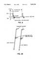
- FIG. 4illustrates the voltage pulse waveform for a typical FES system pulse output
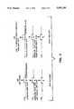
- FIG. 5A-Dprovide voltage vs. time waveforms illustrating the envelope of pulses as distributed to four channels during FES activated walking.
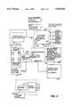
- FIG. 6illustrates an electrical block diagram for a specific alternate embodiment of a FES stimulator box.
- the FES stimulation device under this inventionis a system as in FIG. 1, that comprises of an FES stimulation box 100 that is battery-operated 111, using AA or AAA 1.5 volt batteries or similar batteries, and which includes a stimuli pulse-generator 103, a microprocessor-control circuit 104 and related interface and which has a control panel 107 of pressure switches on its cover.
- the same stimulator box 100also houses the telemetry (ultrasound or radio frequency, or infra-red) receiver in realizations of the invention where telemetry is employed.
- connector interface circuitrycan be provided for non-telemetry applications.
- Itmay also house the audible warning element 108, and may house a low-battery voltage indicator 109 and/or a low-battery visual 110 or audible warning 108 and a display of stimuli levels that is activated to show the level of a given channel when the appropriate control switch is activated by the user.
- the stimulation box 100is connected on its input side 121 to walker-mounted hand (finger) switches (switching unit) 101 and on its output side 124 to the stimulation surface electrodes 102 attached to the patient.
- FIG. 2AThe complete system with a patient is shown in FIG. 2A.
- paraplegic user 99is shown supporting himself with his arms, and by use of the present FES system, with a walker 98 having finger switches control unit 101 mounted thereto, and the FES stimulator box 100 affixed to his belt.
- FIG. 2Billustrates a side view of FIG. 2A
- FIG. 2Cillustrates a top view of the walker 98
- FIG. 2Dprovides a perspective view of the walker 98 and finger switches control unit 101.
- the walker 98is preferably constructed of aluminum pipe, of from 1/2" to 11/2" diameter, ergonomically determined, but typically 1/2" or 3/4".
- the walkershould preferably be a reciprocating walker, using aluminum tubing of approximately 1 inch diameter,
- the right hand-side walker- mounted switching sub-unitconsists of an "on/off" switch 131 for stand-up and sit-down, and of a switch 132 for activating a right step and of a switch 133 for increasing the stimulation level for both the stimulus to the right region of the quadricep muscles (for strengthening right quadricep muscle contractions in standing) and for the stimulus to the right common peroneal nerve (for the right step), and where a short duration pressing of that switch increases the stimuli level to for the right step.
- the left hand-side switching sub-unitincludes a "sit-down" switch 134, such that the sit-down function is activated only when both the left "on/off” switch 131 and the right “off", (namely “sit down") switch 134 are simultaneously pressed, whereas standing requires pressing the right "on/off” switch 131 alone, and where one must start pressing the left “off” switch 134 before pressing the right "on/off” switch 131 and continue pressing it until after releasing the right switch 131.
- the left hand-side sub-unitalso includes a left step switch 135 and a level increase switch 136 that again serves to both increase level of left quadricep and of left step stimuli. Thus, there are 3 switches on each sub unit as illustrated in FIG. 3.
- the switching unit 101is connected for use with an ultrasound transmitter which via a coding circuit, both mounted on the walker, transmit the appropriate codes to the stimulator box.
- the codes as illustrated hereinare:
- This ultra-sound communication link coding circuit and transmitter, together with the appropriate receiver 140 mounted in the stimulation box 100constitute the communications link of 121 of FIG. 1.
- the receiver 140couples the received coded signal for input to the microprocessor circuit 104 where this input is decoded to determine which command is being sent from the input commands (i) to (viii) above.
- a wire linksubstitutes this coded ultrasound link as link 121 above.
- Switch 131can be omitted in some realizations or could serve only for stand-up purposes. In these cases, sit-down is activated by a long duration activation of switch 134 alone, which could be located at the right or left sub-unit with the "stand-up" switch, if employed, being located at the opposite sub-unit.
- inputs (i) to (viii)can alternatively be inputted from the stimulator-mounted switching control panel 107 where, additionally, four further inputs can be generated. These inputs are as follows:
- each function (i) to (xii)may have its own switch.
- any of the above functions relating to a stepshould be considered as functions relating to the gluteus maximus of the same side (right or left), since it is considered that persons with a relatively unstable trunk who require stimulation of the gluteus maximus are not supposed to walk with the present system.
- a corsettemay be worn by the patient, and walking may be executed without stimulating the gluteus maximius if approved by a medical practitioner.
- the microprocessor control circuit of 104has further inputs 123 via internal adjustment circuit 112 which includes a set of pins where applied voltages are input as (4) commands to adjust pulse rate, pulse duration (width), maximal stimuli levels, and can additionally be used to adjust duration of ramp-like envelopes of stimuli amplitudes that are employed at the initialization of stand-up and/or at the end of sit-down, these ramps being a gradual initial-increase/final-decrease of stimuli amplitudes, to avoid a too sudden start/cessation of contraction in stand-up/sit-down. For stand-up, a certain overshoot at the end of the ramps is possible, to provide contraction force for standing-up that is above the force required otherwise for standing, noting the energy required to stand-up from a sitting position.
- the microprocessor 104generates pulse trains and controls at its output 124 the pulse characteristics according to the inputs from 112 and from the switch-inputted functions concerned with stimuli level, which may either modify pulse duration or pulse amplitude. All these are outputted through 125 to the pulse and amplitude amplifier 103 whose output is multiplexed in response to the control as determined by microprocessor 104, and which serves to provide stimuli for all functions (stand, right step, left step).
- the pulse amplifier 103is controlled responsive to the microprocessor via link 126 to output these pulses through the distribution interface circuit 105 as determined by the processor 104 according to the input switches of 101 or of 107.
- the circuit 105thus couples the stimuli to the various skin surface electrodes (2) that are attached with tape to the skin at the appropriate stimulation locations as discussed above. Note that components 103, 104, 105, 107 and 117 are all mounted on the stimulator box 100.
- the stimuli levelsare computed by counting the number of times the appropriate switches are pressed, so that each time an appropriate switch is pressed, the stimuli level at the corresponding channel is increased by a predetermined increment.
- the pulse amplifier 103can consist of a single pulse transformer or, alternatively, of a single solid state cascade of voltage doublers to output a train of pulses which may all be positive or all negative, or may have a positive component followed immediately by a negative component (or vice versa) as illustrated in FIG. 4.
- the pulse-rateis set by microprocessor 104 at approximately 48 pulses per second which is multiplexed at the pulse amplifier's output responsive to microprocessor 104 into 2 channels, each having a rate of 24 pulses per second. If the gluteus maximus and the quads are stimulated, then no step is activated, and the pulse rate is 96 pulses per second divided into 4 channels each having a rate of 24 pulses per second responsive to the microprocessor 104.
- FIGS. 5A-DThe distribution of the stimuli as determined by microprocessor 104 is shown in FIGS. 5A-D, showing the envelopes of stimuli pulse trains for stand and sit-down functions as applied to Right Quads (FIG. 5A) and Left Quads (FIG. 5C), and to the right and left common peroneal nerves for activating Right Step (FIG. 5B) and Left Step (FIG. 5D).
- microprocessor circuit 104computes the actual stimulus level per a given function and outputs via 128 to display circuit 106.
- Display circuit 106can be an LED light-bar display, or alternatively, a numerical read-out display.
- the displaycan be mounted on the stimulator box 100.
- the microprocessor 104also determines when the quad's stimulus level at any one of the two quads reaches a level close to the maximal level, as determined by 104 responsive to the inputs via 112, and then activates an audible alarm 108 to warn the patient that he cannot increase level any further.
- This aspectis important since the patient has no sensation at the quads and cannot determine degree of fatigue at the stimulated muscle.
- the patients armscarry only 2% to 5% of his body weight according to measurements, whereas his stimulated leg muscles carry 95% to 98%. Whenever the patient feels that his arms which support him on the walker carry increased weight, he will tend to increase quads stimuli levels at the appropriate arm side.
- the alarm of 108is to be activated in sufficient time before that complete fatigue level is reached, this level being also adjustable by processor 104 responsive to inputs at 112.
- the audible alarmcan be mounted on the stimulator box 100.
- the microprocessor circuit 104also computes fail-safe provisions to: (i) guarantee that a step can be taken only at one leg at a time; (ii) guarantees that, if no input is received from the walker mounted switches 101 or from the panel switches 107 on the stimulator box 100, concerning commands to one leg or to both, then the patient will always be or remain in the "stand" (both quads "on") mode, to guarantee that with a failure in link 121 or 122, be it an acoustic, IR, radio frequency or wire link or transmitter or receiver failure, that the patient will remain standing and will not fall (and, of course, he still has the walker support); (iii) guarantees that after every step the system automatically returns to the "stand” mode (of both quads being stimulated), and in certain realizations the microprocessor 104 also computes a fail-safe provision that a step is limited in time so that even if a step switch is stuck in the "step” mode, then after a predetermined reasonable time (of the order of a
- That outputmay also be connected, in parallel, to a ZNR type voltage sensitive load.
- This loadpresents to that output a load of no more than a few thousand ohms, if the voltage at that output reaches a certain predetermined value of between 50 and 130 V, and which otherwise presents an additional open circuit.
- a battery supply 111consists of 8 AAA 1.5 VDC batteries, which supplies power to all the circuits of the stimulator box 100 via 130.
- the battery supplyis also coupled to activate a low-battery voltage warning via circuit 109 to provide the audible warning 108 and also a visual flashing warning light 110.
- the "low-battery" warning soundis programmed by the processor 104 to differ from the sound of the stimulus-level-saturation alarm discussed above.
- FIG. 6illustrates a specific embodiment of the stimulator box 100 of FIG. 1, for a wired link 121, with corresponding numerals indicating like elements. Specific electronic device designations are illustrated in FIG. 6, such as the Hitachi HD63701 processor, 104.
Landscapes
- Health & Medical Sciences (AREA)
- Engineering & Computer Science (AREA)
- Life Sciences & Earth Sciences (AREA)
- Biomedical Technology (AREA)
- Animal Behavior & Ethology (AREA)
- General Health & Medical Sciences (AREA)
- Public Health (AREA)
- Veterinary Medicine (AREA)
- Nuclear Medicine, Radiotherapy & Molecular Imaging (AREA)
- Radiology & Medical Imaging (AREA)
- Physical Education & Sports Medicine (AREA)
- Human Computer Interaction (AREA)
- Heart & Thoracic Surgery (AREA)
- Vascular Medicine (AREA)
- Electrotherapy Devices (AREA)
Abstract
Description
Claims (4)
Priority Applications (2)
| Application Number | Priority Date | Filing Date | Title |
|---|---|---|---|
| US07/527,381US5092329A (en) | 1989-04-07 | 1990-05-22 | Microprocessor-controlled multiplexed functional electrical stimulator for surface stimulation in paralyzed patients with safety enhancements |
| CA002074532ACA2074532A1 (en) | 1989-04-07 | 1990-11-26 | Stimulator for surface stimulation in paralyzed patients |
Applications Claiming Priority (5)
| Application Number | Priority Date | Filing Date | Title |
|---|---|---|---|
| US07/335,197US5014705A (en) | 1989-04-07 | 1989-04-07 | Microprocessor-controlled multiplexed functional electrical stimulator for surface stimulation in paralyzed patients |
| US07/527,381US5092329A (en) | 1989-04-07 | 1990-05-22 | Microprocessor-controlled multiplexed functional electrical stimulator for surface stimulation in paralyzed patients with safety enhancements |
| PCT/US1990/006877WO1992009328A1 (en) | 1989-04-07 | 1990-11-26 | Stimulator for surface stimulation in paralyzed patients |
| CA002074532ACA2074532A1 (en) | 1989-04-07 | 1990-11-26 | Stimulator for surface stimulation in paralyzed patients |
| AU70748/91AAU637671B2 (en) | 1989-04-07 | 1990-11-26 | Stimulator for surface stimulation in paralyzed patients |
Related Parent Applications (1)
| Application Number | Title | Priority Date | Filing Date |
|---|---|---|---|
| US07/335,197DivisionUS5014705A (en) | 1989-04-07 | 1989-04-07 | Microprocessor-controlled multiplexed functional electrical stimulator for surface stimulation in paralyzed patients |
Publications (1)
| Publication Number | Publication Date |
|---|---|
| US5092329Atrue US5092329A (en) | 1992-03-03 |
Family
ID=27423760
Family Applications (1)
| Application Number | Title | Priority Date | Filing Date |
|---|---|---|---|
| US07/527,381Expired - Fee RelatedUS5092329A (en) | 1989-04-07 | 1990-05-22 | Microprocessor-controlled multiplexed functional electrical stimulator for surface stimulation in paralyzed patients with safety enhancements |
Country Status (1)
| Country | Link |
|---|---|
| US (1) | US5092329A (en) |
Cited By (36)
| Publication number | Priority date | Publication date | Assignee | Title |
|---|---|---|---|---|
| US5476441A (en)* | 1993-09-30 | 1995-12-19 | Massachusetts Institute Of Technology | Controlled-brake orthosis |
| US5549656A (en)* | 1993-08-16 | 1996-08-27 | Med Serve Group, Inc. | Combination neuromuscular stimulator and electromyograph system |
| WO1997004705A1 (en)* | 1995-07-31 | 1997-02-13 | Motorola Inc. | Hybrid fes and active orthosis method and system for controlling the movement of a limb |
| WO1997004833A1 (en)* | 1995-07-31 | 1997-02-13 | Motorola Inc. | Fes method and system for controlling the movement of a limb |
| US5643330A (en)* | 1994-01-24 | 1997-07-01 | Medtronic, Inc. | Multichannel apparatus for epidural spinal cord stimulation |
| WO1999062594A1 (en)* | 1998-06-03 | 1999-12-09 | Neurocontrol Corporation | Percutaneous intramuscular stimulation system |
| AU729913B3 (en)* | 2000-05-24 | 2001-02-15 | Glenn Rosendahl | System and method for assisting walking |
| US6308102B1 (en) | 1999-09-29 | 2001-10-23 | Stimsoft, Inc. | Patient interactive neurostimulation system and method |
| US20030204224A1 (en)* | 2002-04-26 | 2003-10-30 | Medtronic, Inc. | Programmable waveform pulses for an implantable medical device |
| US6644976B2 (en) | 2001-09-10 | 2003-11-11 | Epoch Innovations Ltd | Apparatus, method and computer program product to produce or direct movements in synergic timed correlation with physiological activity |
| US6654642B2 (en) | 1999-09-29 | 2003-11-25 | Medtronic, Inc. | Patient interactive neurostimulation system and method |
| US20040015203A1 (en)* | 2000-05-08 | 2004-01-22 | Mcgraw Michael B. | Multi-functional portable electro-medical device |
| US20040044381A1 (en)* | 2000-08-14 | 2004-03-04 | Duncan Michael Robert | Muscle fatigue meter |
| US20040133241A1 (en)* | 2001-08-23 | 2004-07-08 | Nadtochiy Alexander I. | Adaptive electrostimulator |
| US20040236387A1 (en)* | 1998-06-03 | 2004-11-25 | Neurocontrol Corporation | Treatment of shoulder dysfunction using a percutaneous intramuscular stimulation system |
| US7072721B1 (en)* | 2002-11-01 | 2006-07-04 | Cecilio Trent | Electrode vest for electrical stimulation of the abdomen and back |
| US20060149338A1 (en)* | 2005-01-06 | 2006-07-06 | Flaherty J C | Neurally controlled patient ambulation system |
| US20060217768A1 (en)* | 2005-01-28 | 2006-09-28 | Felix Buhlmann | Independent protection system for an electrical muscle stimulation apparatus and method of using same |
| US7151914B2 (en) | 2001-08-21 | 2006-12-19 | Medtronic, Inc. | Transmitter system for wireless communication with implanted devices |
| US20080042853A1 (en)* | 2005-04-06 | 2008-02-21 | Levi Dempsey | Bio-feedback walker device |
| US20090018612A1 (en)* | 2000-08-14 | 2009-01-15 | Neopraxis Pty Ltd | Exercise Apparatus For A Person With Muscular Deficiency |
| US20100042180A1 (en)* | 2005-04-19 | 2010-02-18 | Compex Technologies, Inc | Electrical stimulation device and method for therapeutic treatment and pain management |
| US20100063411A1 (en)* | 2003-11-09 | 2010-03-11 | Cyberkinetics, Inc. | Calibration systems and methods for neural interface devices |
| US7881780B2 (en) | 2005-01-18 | 2011-02-01 | Braingate Co., Llc | Biological interface system with thresholded configuration |
| US7991461B2 (en) | 2005-01-06 | 2011-08-02 | Braingate Co., Llc | Patient training routine for biological interface system |
| US8095209B2 (en) | 2005-01-06 | 2012-01-10 | Braingate Co., Llc | Biological interface system with gated control signal |
| US8560041B2 (en) | 2004-10-04 | 2013-10-15 | Braingate Co., Llc | Biological interface system |
| US8620438B1 (en) | 2007-02-13 | 2013-12-31 | Encore Medical Asset Corporation | Method and apparatus for applying neuromuscular electrical stimulation |
| US8812096B2 (en) | 2005-01-10 | 2014-08-19 | Braingate Co., Llc | Biological interface system with patient training apparatus |
| US9272139B2 (en) | 2010-07-01 | 2016-03-01 | Marilyn J. Hamilton | Universal closed-loop electrical stimulation system |
| US9333345B2 (en) | 2013-10-03 | 2016-05-10 | Ensilver Canada | Electrical stimulation for a functional electrical stimulation system |
| US9364657B2 (en) | 2014-10-31 | 2016-06-14 | Ensilver Canada | Cuff unit for a functional electrical stimulation system |
| US9375569B2 (en) | 2013-10-03 | 2016-06-28 | Ensilver Canada | Controller unit for a functional electrical stimulation (FES) orthotic system |
| US9375570B2 (en) | 2013-10-03 | 2016-06-28 | Ensilver Canada | Sensor unit for a functional electrical stimulation (FES) orthotic system |
| WO2018220374A1 (en) | 2017-05-31 | 2018-12-06 | Nigel Charles Verity | Apparatus for neuromuscular stimulation |
| US12318610B1 (en) | 2019-10-18 | 2025-06-03 | Enlighten Mobility Llc | Gait trainer with neuromodulation integration |
Citations (10)
| Publication number | Priority date | Publication date | Assignee | Title |
|---|---|---|---|---|
| US4147171A (en)* | 1977-01-28 | 1979-04-03 | Greene Ronald W | Transcutaneous pain control and/or muscle stimulating apparatus |
| US4421336A (en)* | 1982-09-14 | 1983-12-20 | Wright State University | Vehicle for the paralyzed |
| US4524773A (en)* | 1983-08-24 | 1985-06-25 | The John Hopkins University | Apparatus for inhibiting self-injurious behavior (SIB) in patients |
| US4569352A (en)* | 1983-05-13 | 1986-02-11 | Wright State University | Feedback control system for walking |
| US4642769A (en)* | 1983-06-10 | 1987-02-10 | Wright State University | Method and apparatus for providing stimulated exercise of paralyzed limbs |
| US4724842A (en)* | 1982-05-19 | 1988-02-16 | Charters Thomas H | Method and apparatus for muscle stimulation |
| US4760850A (en)* | 1986-05-15 | 1988-08-02 | Wright State University | Method for balancing assistance |
| US4796631A (en)* | 1987-06-11 | 1989-01-10 | Grigoryev Leon M | Electrical muscle stimulator for knee stabilization |
| US4838272A (en)* | 1987-08-19 | 1989-06-13 | The Regents Of The University Of California | Method and apparatus for adaptive closed loop electrical stimulation of muscles |
| US4934368A (en)* | 1988-01-21 | 1990-06-19 | Myo/Kinetics Systems, Inc. | Multi-electrode neurological stimulation apparatus |
- 1990
- 1990-05-22USUS07/527,381patent/US5092329A/ennot_activeExpired - Fee Related
Patent Citations (10)
| Publication number | Priority date | Publication date | Assignee | Title |
|---|---|---|---|---|
| US4147171A (en)* | 1977-01-28 | 1979-04-03 | Greene Ronald W | Transcutaneous pain control and/or muscle stimulating apparatus |
| US4724842A (en)* | 1982-05-19 | 1988-02-16 | Charters Thomas H | Method and apparatus for muscle stimulation |
| US4421336A (en)* | 1982-09-14 | 1983-12-20 | Wright State University | Vehicle for the paralyzed |
| US4569352A (en)* | 1983-05-13 | 1986-02-11 | Wright State University | Feedback control system for walking |
| US4642769A (en)* | 1983-06-10 | 1987-02-10 | Wright State University | Method and apparatus for providing stimulated exercise of paralyzed limbs |
| US4524773A (en)* | 1983-08-24 | 1985-06-25 | The John Hopkins University | Apparatus for inhibiting self-injurious behavior (SIB) in patients |
| US4760850A (en)* | 1986-05-15 | 1988-08-02 | Wright State University | Method for balancing assistance |
| US4796631A (en)* | 1987-06-11 | 1989-01-10 | Grigoryev Leon M | Electrical muscle stimulator for knee stabilization |
| US4838272A (en)* | 1987-08-19 | 1989-06-13 | The Regents Of The University Of California | Method and apparatus for adaptive closed loop electrical stimulation of muscles |
| US4934368A (en)* | 1988-01-21 | 1990-06-19 | Myo/Kinetics Systems, Inc. | Multi-electrode neurological stimulation apparatus |
Non-Patent Citations (2)
| Title |
|---|
| Description and Application of a System for Locomotor Rehabilitation, Medical & Biomedical Engineering & Computing, May 1987, pp. 341 344.* |
| Description and Application of a System for Locomotor Rehabilitation, Medical & Biomedical Engineering & Computing, May 1987, pp. 341-344. |
Cited By (65)
| Publication number | Priority date | Publication date | Assignee | Title |
|---|---|---|---|---|
| US5549656A (en)* | 1993-08-16 | 1996-08-27 | Med Serve Group, Inc. | Combination neuromuscular stimulator and electromyograph system |
| US5476441A (en)* | 1993-09-30 | 1995-12-19 | Massachusetts Institute Of Technology | Controlled-brake orthosis |
| US5643330A (en)* | 1994-01-24 | 1997-07-01 | Medtronic, Inc. | Multichannel apparatus for epidural spinal cord stimulation |
| WO1997004705A1 (en)* | 1995-07-31 | 1997-02-13 | Motorola Inc. | Hybrid fes and active orthosis method and system for controlling the movement of a limb |
| WO1997004833A1 (en)* | 1995-07-31 | 1997-02-13 | Motorola Inc. | Fes method and system for controlling the movement of a limb |
| US5748845A (en)* | 1995-07-31 | 1998-05-05 | Motorola, Inc. | FES method and system for controlling the movement of a limb |
| WO1999062594A1 (en)* | 1998-06-03 | 1999-12-09 | Neurocontrol Corporation | Percutaneous intramuscular stimulation system |
| US20060009816A1 (en)* | 1998-06-03 | 2006-01-12 | Neurocontrol Corporation | Percutaneous intramuscular stimulation system |
| US20080177351A1 (en)* | 1998-06-03 | 2008-07-24 | Neurocontrol Corporation | Method of providing percutaneous intramuscular stimulation |
| US20020077572A1 (en)* | 1998-06-03 | 2002-06-20 | Neurocontrol Corporation | Percutaneous intramuscular stimulation system |
| US20080065171A1 (en)* | 1998-06-03 | 2008-03-13 | Neurocontrol Corporation | Treatment of shoulder dysfunction using a percutaneous intramuscular stimulation system |
| US8249713B2 (en) | 1998-06-03 | 2012-08-21 | Spr Therapeutics, Llc | Treatment of shoulder dysfunction using a percutaneous intramuscular stimulation system |
| US6845271B2 (en) | 1998-06-03 | 2005-01-18 | Neurocontrol Corporation | Treatment of shoulder dysfunction using a percutaneous intramuscular stimulation system |
| US20040236387A1 (en)* | 1998-06-03 | 2004-11-25 | Neurocontrol Corporation | Treatment of shoulder dysfunction using a percutaneous intramuscular stimulation system |
| US9314628B2 (en) | 1999-09-29 | 2016-04-19 | Medtronic, Inc. | Patient interactive neurostimulation system and method |
| US20040059395A1 (en)* | 1999-09-29 | 2004-03-25 | Medtronic, Inc. | Patient interactive neurostimulation system and method |
| US20080275529A1 (en)* | 1999-09-29 | 2008-11-06 | Medtronic, Inc. | Patient interactive neurostimulation system and method |
| US6654642B2 (en) | 1999-09-29 | 2003-11-25 | Medtronic, Inc. | Patient interactive neurostimulation system and method |
| US6308102B1 (en) | 1999-09-29 | 2001-10-23 | Stimsoft, Inc. | Patient interactive neurostimulation system and method |
| US7386348B2 (en) | 1999-09-29 | 2008-06-10 | Medtronic, Inc. | Patient interactive neurostimulation system and method |
| US20040015203A1 (en)* | 2000-05-08 | 2004-01-22 | Mcgraw Michael B. | Multi-functional portable electro-medical device |
| US6988005B2 (en) | 2000-05-08 | 2006-01-17 | International Rehabilitative Sciences, Inc. | Multi-functional portable electro-medical device |
| AU729913B3 (en)* | 2000-05-24 | 2001-02-15 | Glenn Rosendahl | System and method for assisting walking |
| US20090018612A1 (en)* | 2000-08-14 | 2009-01-15 | Neopraxis Pty Ltd | Exercise Apparatus For A Person With Muscular Deficiency |
| US20130131757A1 (en)* | 2000-08-14 | 2013-05-23 | Michael Robert Duncan | Muscle fatigue meter |
| US20100069796A1 (en)* | 2000-08-14 | 2010-03-18 | Neopraxis Pty Ltd. | Muscle fatigue meter |
| US20040044381A1 (en)* | 2000-08-14 | 2004-03-04 | Duncan Michael Robert | Muscle fatigue meter |
| EP1309275A4 (en)* | 2000-08-14 | 2005-02-02 | Neopraxis Pty Ltd | Muscle fatigue meter |
| US7151914B2 (en) | 2001-08-21 | 2006-12-19 | Medtronic, Inc. | Transmitter system for wireless communication with implanted devices |
| US20040133241A1 (en)* | 2001-08-23 | 2004-07-08 | Nadtochiy Alexander I. | Adaptive electrostimulator |
| US6644976B2 (en) | 2001-09-10 | 2003-11-11 | Epoch Innovations Ltd | Apparatus, method and computer program product to produce or direct movements in synergic timed correlation with physiological activity |
| US20090259278A1 (en)* | 2002-04-26 | 2009-10-15 | Medtronic, Inc. | Programmable waveform pulses for an implantable medical device |
| US7483748B2 (en) | 2002-04-26 | 2009-01-27 | Medtronic, Inc. | Programmable waveform pulses for an implantable medical device |
| US20030204224A1 (en)* | 2002-04-26 | 2003-10-30 | Medtronic, Inc. | Programmable waveform pulses for an implantable medical device |
| US7072721B1 (en)* | 2002-11-01 | 2006-07-04 | Cecilio Trent | Electrode vest for electrical stimulation of the abdomen and back |
| US8386050B2 (en) | 2003-11-09 | 2013-02-26 | Braingate Co., Llc | Calibration systems and methods for neural interface devices |
| US20100063411A1 (en)* | 2003-11-09 | 2010-03-11 | Cyberkinetics, Inc. | Calibration systems and methods for neural interface devices |
| US8560041B2 (en) | 2004-10-04 | 2013-10-15 | Braingate Co., Llc | Biological interface system |
| US7901368B2 (en)* | 2005-01-06 | 2011-03-08 | Braingate Co., Llc | Neurally controlled patient ambulation system |
| US7991461B2 (en) | 2005-01-06 | 2011-08-02 | Braingate Co., Llc | Patient training routine for biological interface system |
| US8095209B2 (en) | 2005-01-06 | 2012-01-10 | Braingate Co., Llc | Biological interface system with gated control signal |
| US20060149338A1 (en)* | 2005-01-06 | 2006-07-06 | Flaherty J C | Neurally controlled patient ambulation system |
| US8812096B2 (en) | 2005-01-10 | 2014-08-19 | Braingate Co., Llc | Biological interface system with patient training apparatus |
| US8060194B2 (en) | 2005-01-18 | 2011-11-15 | Braingate Co., Llc | Biological interface system with automated configuration |
| US7881780B2 (en) | 2005-01-18 | 2011-02-01 | Braingate Co., Llc | Biological interface system with thresholded configuration |
| US8140165B2 (en) | 2005-01-28 | 2012-03-20 | Encore Medical Asset Corporation | Independent protection system for an electrical muscle stimulation apparatus and method of using same |
| US9808619B2 (en) | 2005-01-28 | 2017-11-07 | Encore Medical Asset Corporation | Independent protection system for an electrical muscle stimulation apparatus and method of using same |
| US20060217768A1 (en)* | 2005-01-28 | 2006-09-28 | Felix Buhlmann | Independent protection system for an electrical muscle stimulation apparatus and method of using same |
| US20080042853A1 (en)* | 2005-04-06 | 2008-02-21 | Levi Dempsey | Bio-feedback walker device |
| US7385514B2 (en)* | 2005-04-06 | 2008-06-10 | Levi Dempsey | Bio-feedback walker device |
| US8958883B2 (en) | 2005-04-19 | 2015-02-17 | Pierre-Yves Mueller | Electrical stimulation device and method for therapeutic treatment and pain management |
| US10328260B2 (en) | 2005-04-19 | 2019-06-25 | Djo, Llc | Electrical stimulation device and method for therapeutic treatment and pain management |
| US9669212B2 (en) | 2005-04-19 | 2017-06-06 | Djo, Llc | Electrical stimulation device and method for therapeutic treatment and pain management |
| US20100042180A1 (en)* | 2005-04-19 | 2010-02-18 | Compex Technologies, Inc | Electrical stimulation device and method for therapeutic treatment and pain management |
| US8620438B1 (en) | 2007-02-13 | 2013-12-31 | Encore Medical Asset Corporation | Method and apparatus for applying neuromuscular electrical stimulation |
| US9352151B2 (en) | 2007-02-13 | 2016-05-31 | Encore Medical Asset Corporation | Method and apparatus for applying neuromuscular electrical stimulation |
| US9669211B2 (en) | 2007-02-13 | 2017-06-06 | Encore Medical Asset Corporation | Method and apparatus for applying neuromuscular electrical stimulation |
| US9272139B2 (en) | 2010-07-01 | 2016-03-01 | Marilyn J. Hamilton | Universal closed-loop electrical stimulation system |
| US9375569B2 (en) | 2013-10-03 | 2016-06-28 | Ensilver Canada | Controller unit for a functional electrical stimulation (FES) orthotic system |
| US9375570B2 (en) | 2013-10-03 | 2016-06-28 | Ensilver Canada | Sensor unit for a functional electrical stimulation (FES) orthotic system |
| US9333345B2 (en) | 2013-10-03 | 2016-05-10 | Ensilver Canada | Electrical stimulation for a functional electrical stimulation system |
| US9364657B2 (en) | 2014-10-31 | 2016-06-14 | Ensilver Canada | Cuff unit for a functional electrical stimulation system |
| WO2018220374A1 (en) | 2017-05-31 | 2018-12-06 | Nigel Charles Verity | Apparatus for neuromuscular stimulation |
| US11484709B2 (en) | 2017-05-31 | 2022-11-01 | Nigel Charles VERITY | Apparatus for neuromuscular stimulation |
| US12318610B1 (en) | 2019-10-18 | 2025-06-03 | Enlighten Mobility Llc | Gait trainer with neuromodulation integration |
Similar Documents
| Publication | Publication Date | Title |
|---|---|---|
| US5092329A (en) | Microprocessor-controlled multiplexed functional electrical stimulator for surface stimulation in paralyzed patients with safety enhancements | |
| US5014705A (en) | Microprocessor-controlled multiplexed functional electrical stimulator for surface stimulation in paralyzed patients | |
| US5081989A (en) | Microprocessor-controlled enhanced multiplexed functional electrical stimulator for surface stimulation in paralyzed patients | |
| US11389110B2 (en) | Automated adaptive muscle stimulation method and apparatus | |
| AU686180B2 (en) | Nerve stimulating device and associated support device | |
| US4735206A (en) | Method and apparatus for defibrillating and pacing the heart | |
| EP1263497B1 (en) | An automatic defibrillator module for integration with standard patient monitoring equipment | |
| US7162305B2 (en) | Functional electrical stimulation system | |
| US4340063A (en) | Stimulation device | |
| US7221980B2 (en) | Electrostimulation system with electromyographic and visual biofeedback | |
| US20080177351A1 (en) | Method of providing percutaneous intramuscular stimulation | |
| US20020193844A1 (en) | Combination electrode-battery assembly for a miniature wireless transcutaneous electrical neuro or muscular-stimulation unit | |
| US4690146A (en) | Neuromuscular stimulating apparatus | |
| WO1992009328A1 (en) | Stimulator for surface stimulation in paralyzed patients | |
| Nohama et al. | Electrotactile stimulator for artificial proprioception | |
| CA2074532A1 (en) | Stimulator for surface stimulation in paralyzed patients | |
| Graupe et al. | Above-and below-lesion EMG pattern mapping for controlling electrical stimulation of paraplegics to facilitate unbraced walker-assisted walking | |
| Perkins | Versatile three-channel stimulation controller for restoration of bladder function in paraplegia | |
| RU2832608C1 (en) | Current electrostimulating device for prevention of bedsores | |
| EP1051221B1 (en) | Muscle electrostimulator conformed in such a way as to avoid sensations of pain and reddening of the skin | |
| Petrucelli et al. | A SERIAL TO PARALLEL INTERFACE SYSTEM FOR TENS PAIN SUPPRESSION | |
| GB2127696A (en) | Electrical transcutaneous stimulator | |
| KR20050010215A (en) | Low frequency medical apparatus synchronized with skin resistance value and heart beat |
Legal Events
| Date | Code | Title | Description |
|---|---|---|---|
| AS | Assignment | Owner name:SIGMEDICS, INC., ILLINOIS Free format text:ASSIGNMENT OF ASSIGNORS INTEREST.;ASSIGNORS:ARBER, AMIHADAR;GRAUPE, DANIEL;REEL/FRAME:005342/0447 Effective date:19900427 | |
| AS | Assignment | Owner name:SANDERLING VENTURES, CALIFORNIA Free format text:SECURITY INTEREST;ASSIGNOR:SIGMEDICS, INC.;REEL/FRAME:006296/0592 Effective date:19921109 | |
| AS | Assignment | Owner name:SANDERLING VENTURE PARTNERS, CALIFORNIA Free format text:RERECORD TO CORRECT ERROR IN RECORDATION DATE ON REEL 7482, FRAME 0841.;ASSIGNOR:SIGMEDICS, INC.;REEL/FRAME:007690/0562 Effective date:19950313 | |
| AS | Assignment | Owner name:SANDERLING VENTURE PARTNERS, CALIFORNIA Free format text:SECURITY INTEREST;ASSIGNOR:SIGMEDICS, INC.;REEL/FRAME:007482/0841 Effective date:19950313 | |
| REMI | Maintenance fee reminder mailed | ||
| FEPP | Fee payment procedure | Free format text:PAYOR NUMBER ASSIGNED (ORIGINAL EVENT CODE: ASPN); ENTITY STATUS OF PATENT OWNER: SMALL ENTITY | |
| FPAY | Fee payment | Year of fee payment:4 | |
| SULP | Surcharge for late payment | ||
| REMI | Maintenance fee reminder mailed | ||
| LAPS | Lapse for failure to pay maintenance fees | ||
| FP | Lapsed due to failure to pay maintenance fee | Effective date:20000303 | |
| STCH | Information on status: patent discontinuation | Free format text:PATENT EXPIRED DUE TO NONPAYMENT OF MAINTENANCE FEES UNDER 37 CFR 1.362 |