US5091960A - High-speed image rendering method using look-ahead images - Google Patents
High-speed image rendering method using look-ahead imagesDownload PDFInfo
- Publication number
- US5091960A US5091960AUS07/249,589US24958988AUS5091960AUS 5091960 AUS5091960 AUS 5091960AUS 24958988 AUS24958988 AUS 24958988AUS 5091960 AUS5091960 AUS 5091960A
- Authority
- US
- United States
- Prior art keywords
- image
- look
- ahead
- image data
- interest
- Prior art date
- Legal status (The legal status is an assumption and is not a legal conclusion. Google has not performed a legal analysis and makes no representation as to the accuracy of the status listed.)
- Expired - Lifetime
Links
Images


Classifications
- G—PHYSICS
- G06—COMPUTING OR CALCULATING; COUNTING
- G06T—IMAGE DATA PROCESSING OR GENERATION, IN GENERAL
- G06T15/00—3D [Three Dimensional] image rendering
- G06T15/10—Geometric effects
- G06T15/20—Perspective computation
Definitions
- High-speed image processing equipmenthas made possible the processing of image data to present new scenes or perspectives of an object from image data of a different scene or perspective.
- digital elevation information of a geographical regioncan be processed to generate a variety of different two and one-half dimensional representations of the terrain.
- the new perspective scenes of the terraincan be generated by rendering techniques to give the observer a perspective view of the terrain from any point in space. From a series of such perspective views of the subject terrain, a person can experience a hypothetical flight over the terrain without actually experiencing a true flight. It can be appreciated that such a rendering technique is highly advantageous in military and aeronautical applications.
- Image data related to three-dimensional objectsmay also be rendered to further define, clarify, create, etc., new images which in reality are difficult or impossible to observe.
- Such applicationsinclude physiological cat-scans, X-rays, sonograms, nuclear magnetic resonance, etc.
- perspective viewscan be generated using translucency, opacity or color parameters to create new perspective views to accentuate body tissues or other material.
- Image renderingcan be achieved by various techniques, including image ray tracing.
- Ray tracing techniquesare disclosed in connection with volume rendering in the technical article entitled, "Display of Surfaces From Volume Data", by Marc Levoy, IEEE, Computer Graphics and Applications, May, 1988 pages 29-37. According to such techniques, and other similar ray tracing techniques, point is established in free space from which hypothetical rays are extended toward a reflective image of the object.
- the image processorproceeds in successive increments along each ray to determine if the surface of the object has been penetrated. Each ray increment or section corresponds to a pixel location associated with the reflective image. When the surface of the image is penetrated by a particular ray section, the pixel information or resampled information thereof, is stored for later presentation of the new perspective view.
- each rayis also incrementally traversed, noting whether any point of interest is within a specified volumetric vicinity.
- Regions of interestmay include arbitrary intensity ranges or opacity ranges existing within a given sphere in which the ray section is centered.
- the disclosed rendering method and associated apparatussubstantially reduces or eliminates the disadvantages and shortcomings associated with the prior art techniques.
- the reflective data of the imageis preprocessed before rendering to develop one or more look-ahead images which are referenced during the actual rendering process.
- the method and apparatus of the inventiondetermines how far along the ray one can proceed first by large steps and then by smaller steps to encounter pertinent image data without passing or overlooking other significant image data.
- the jumps by which one can proceed along each ray without bypassing pertinent image dataare determined at any point along the ray by referring to the look-ahead image.
- Preferred embodimentsare disclosed for both 2.5 and 3 dimensional rendering.
- a first look-ahead imageis developed by preprocessing the reflective image data to determine, for each ray, whether or not a single jump, equal to many small increments, can be executed and yet not penetrate the object surface. If so, a digital notation is stored in the look-ahead image to indicate that such a large jump can be accomplished thereby eliminating the many small individual jumps which would otherwise be processed. If a single large jump cannot be accomplished without penetrating the object surface, then the preprocessing method causes an execution of an intermediate jump equal to several small increments. A determination is again made to ascertain if the image surface is thereby penetrated.
- a second or intermediate look-ahead imagestores therein a predefined notation corresponding to the pixel information associated with the ray section which penetrated the surface. If the intermediate step does penetrate the object surface, then the smallest increments are executed using the elevation image data itself to determine exactly in three dimensional space where the object's surface exists along the ray. In essence, three look-ahead images are provided, one being the actual elevation image data itself.
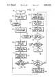
- FIG. 1illustrates in block diagram form image processing apparatus adapted for carrying out the method of the invention
- FIG. 2illustrates image ray tracing employed in connection with a 2.5 dimensional elevation image
- FIG. 3illustrates a flow diagram of the major steps in carrying out the high-speed rendering operation of the invention using several fixed distance look-ahead images containing worst case elevation values in 2.5 dimensional rendering;
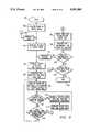
- FIGS. 4a-4billustrate image ray tracing employed in connection with a three dimensional image volume
- FIG. 5illustrates a flow diagram of the major steps in carrying out the high-speed rendering operation of the invention with a single look-ahead image containing variable distances to a particular type or quality of pixels.
- FIG. 1illustrates image processing equipment adapted for carrying out the high-speed rendering technique of the invention.
- an image processor 10for processing image data and presenting the same on a monitor 12 for viewing by an observer.
- the image processor 10includes, among other circuits, an arithmetic logic unit (ALU) 14 coupled to an image memory 16.
- ALU 14may be of conventional design, or of highly sophisticated circuits, for processing image data supplied to it in the nature of pixel data.
- the pixel datawhether it be 8-bit or 16-bit words, are stored in the image memory 16 and are accessible by the ALU 14.
- the image memory 16includes a number of planes 18-24, each for storing a different type of image data.
- image memory plane 18may store image data corresponding to a red color intensity
- planes 20 and 22may store respectively green and blue image intensity information.
- An overlay plane 24may be utilized for storing other information, such as overlay or look-ahead data, as set forth in more detail below.
- Other types of memory structuresmay be employed with equal effectiveness to store all the image data necessary to carry out the rendering function.
- a keyboard 26is typically associated with the image processor 10 to control the operations thereof and to provide different renderings of an image on the monitor 12.
- a high-speed image processor 10 adapted for operation according to the inventionis described in more detail in co-pending U.S.
- Patent Applicationentitled, "High Speed Image Processing Computer", by Pfeiffer et al. filed Sept. 14, 1987, Ser. No. 097,664, now U.S. Pat. No. 4,985,848, the disclosure of which is incorporated herein by reference.
- the image memorytypically is written by the processor to store reflective image data.
- the image memory 16stores amplitude or elevation information corresponding to each pixel location associated with the image.
- a destination imageis also stored in the image memory 16.
- the pixel data of the destination imageresults from the rendering operation and comprises, for example, the perspective view of the image from the given spatial point 34 (FIG. 2).
- the destination imageis transferred to the monitor 12 by the image processor 10.
- FIG. 2is the topography of a geographical object 28 which is to be rendered according to the various perspective views desired.
- exemplary pixel locations 30which are associated with elevation or amplitude arrows 32 which depict the elevation of the terrain 28 directly above each pixel location 30.
- each pixel location 30stores binary data representative of the associated elevation of the geographical feature.
- image memory 16comprises rows and columns of pixel storage locations 30 forming an array (e.g. 512 ⁇ 512).
- the elevation data stored at each pixel location 30can be developed using geographical data of the actual terrain, or by employing different photographs of a geographical area and triangulation techniques for arriving at the elevation of each section of the terrain.
- image datacan be developed to represent the elevation of a geographical terrain which is desired to be the subject matter of image processing and rendering it is well known in the art.
- rendering techniquescan be employed to create different perspectives or views of the terrain 28 by processing the information stored at each pixel location 30. Without viewing the actual geographical terrain, the rendering operation can present to an observer via the monitor 12 a perspective view, for example, from the spatial point 34, 36 or any other point in the image space. As can be appreciated, the perspective view from point 34 will be different from that observed from point 36.
- Rendering of the image dataprovides the capability for viewing the perspectives of the geographical terrain 28 from the vantage points 34 or 36, or any other point in space. It is to be understood that while the example is described herein in terms of geographical terrain, any other image which can be characterized by elevation parameters can be processed and rendered accordingly.
- a point 34 of particular interest in spaceis chosen as the vantage point. Because the elevation characteristics of the new perspective are not known with the respect to the chosen vantage point 34, conventional rendering is carried out by extending a number of rays, such as 38, from the spatial point 34, in an arcuate area from the point 34 to all points on the terrain 28. Each ray 38 is conventionally traversed in an incremental manner along the ray segments 40. As each ray segment 40 is traversed, the rendering algorithm checks to see whether the surface of the terrain 28 has been penetrated. In so doing, it is determined whether the elevation data stored at selected pixel locations corresponds to the spatial point of the ray segment.
- the necessity for executing image data processing at each ray segment 40is obviated by providing look-ahead images to determine the extent by which one can jump over a number of ray segments 40 to eliminate the processing thereof, while yet not penetrating the surface of the terrain 28.
- the image data stored in the look-ahead image 24comprises elevation information as viewed from a desired perspective, such as the spatial point 34.
- Conventional dilation algorithmsare available for generating the look-ahead data with respect to a given spatial point. Essentially, such algorithms search for a maximum elevation value in a neighborhood around a ray segment, and more particularly seek a worst case elevation within, for example, a fixed radius around a ray segment.
- a fixed circular radius for dilation purposesis not required, but only a pie-shaped or arcuate area, since the terrain object 28 can be viewed entirely from a small angular area in which all the rays extend from the spatial point 34 to any point on the surface of the terrain object 28.
- FIG. 3there is illustrated a flow chart of image processor operations for carrying out the high-speed rendering feature of the invention.
- image data and associated memory areasare utilized.
- a reflective imageis stored in the image memory 16, which image comprises an array of pixel locations storing the gray value intensity information of the source image.
- three memory areaswould be utilized to store red, green and blue data of the source image.
- An elevation imageis also stored in the image memory 16 in an array of pixel locations an elevation image. Pixel locations of the elevation image have stored therein amplitude information of the source image.
- the amplitude data stored in the elevation imagecan be dilated according to conventional algorithms to generate data which is stored in one or more look-ahead images of the invention.
- two new look-ahead imagesare utilized for storing elevation derived information, a first image corresponding to a first jump size along a ray trace, and a second look-ahead image for storing like information corresponding to a second smaller jump size along the ray trace.
- the elevation imageis dilated to precalculate, with respect to each ray trace, the worst case or highest elevation in a given neighborhood.
- the neighborhoodcan be arbitrarily defined, such as a circle with a radius R, a pie-shaped area, or other shape suitable for the particular application.
- the first look-ahead imageis generated having dilated data yielding the highest elevation within sixty-four segments of a ray trace 38.
- a second look-ahead imageis generated having information defining the highest elevation in sixteen segment steps of each ray trace 38.
- the information stored in the reflective image area of the image memory 16can be utilized as a look-ahead image defining the highest elevation for each segment 40 of each ray trace 38.
- the rendering operationis commenced at a predefined processor starting point, such as shown by reference character 42.
- a predefined processor starting pointsuch as shown by reference character 42.
- the look-ahead imagesare sequentially written with the dilated information for use during the rendering operation.
- the spatial point 34(FIG. 2) is established for ray tracing by the interaction between an operator utilizing the keyboard 26 and the image processor 10 (FIG. 1).
- a spatial point, such as 34 or 36 (FIG. 2)is selected from which it is desired to obtain a perspective view of the terrain 28.
- This programmed operationis shown by reference character 48. Once a spatial point for ray tracing is selected, an angular direction of the first ray 38 is selected, as is a first jump size.
- the first ray 38 selectedmay be arbitrary, but may be that which corresponds to the upper-leftmost ray which will strike the terrain 28.
- the first jump size according to the inventionis selected as equivalent to sixty-four segments 40. That is, jumps in increments of 64 ray trace segments will be carried out according to such program block.
- the image processor 10jumps along the selected first ray 38, and particularly to the 64th segment thereof.
- the jump size of 64 ray segmentswas established according to the processing of block 50.
- the image processor 10is programmed to check whether or not any segment to the 64th ray segment penetrates the object of the terrain surface 28. This is accomplished by determining the vertical height or the Z-axis dimension corresponding to the spatial location of the 64th ray section. A mathematical subtraction is carried out between the noted Z-axis dimension and the elevation information stored in the pixel location associated with the 64th segment of the noted ray 38. If the object surface is not penetrated, control is branched back to block 52 where another large jump of 64 ray is executed.
- the processor 10continues testing every 64th ray segment to determine if the object surface has been penetrated, and if so, control is branched to block 56.
- the processor 10tests whether or not the current ray 38 tested corresponds approximately to the same height as the surface, or if indeed whether such ray has penetrated the surface. If the ray has indeed penetrated the surface of the object, i.e., does not correspond to the surface elevation at that point, the processor 10 continues to block 58, wherein the jump size is reduced and return is made back to block 52.
- the second jump sizeis established as sixteen ray segments.
- the jump sizesare rather arbitrary, but can be predefined to optimize the rendering time according to the particular types of object or images being processed.
- the processorreturns to the start of a jump point in which the object surface was penetrated, and then proceeds sixteen segments to conduct tests to determine whether the object surface has been penetrated (block 54).
- the second look-ahead imageis utilized to determined whether or not a pertinent maximum elevation exists anywhere within a desired neighborhood of the current jump point. Again, if the object surface is penetrated during the current jump being processed, the jump size is again reduced, whereupon the processor 10 conducts the test of block 54 at each pixel location corresponding to each ray segment 40. In other words, the jump size is reduced to unity, and the elevation image is analyzed to determine the elevation data at each ray segment location.
- one ray segmentwill correspond to the surface of the object 28, whereupon the processor 10 branches to program flow block 60.
- processingis expedited as it is not necessary to carry out the determination of block 54 for each ray segment 40.
- the processor 10 of the inventionwould execute only four tests according to program flow block 54 rather than the traditional 129 process calculations.
- image rendering according to the inventioncan be expedited by a factor of three to five times that of prior two and one-half dimensional rendering techniques.
- Rendering from a typical eye point slightly above the surface and directed toward the horizonachieves a speed-up of about three to four times with the technique of the invention.
- a restriction in which the eye points falls within a 45° rangeproduces a five to six factor in the speed-up of all ray tracing from such eye points.
- the source or reflective image datais resampled to generate new pixel data which will be subsequently utilized to present the desired perspective view of the image during the rendering process.
- the resamplingmay involve an averaging or interpolation of the pixels in the neighborhood of the pixel of interest.
- the resampled pixelis stored in the destination image for presentation on the monitor 12. The actual presentation, or reading of the destination image from the image memory 16 is carried out, as noted in block 64.
- the foregoingillustrates the expedited tracing of a single ray 38 to determine the spatial location of surface of the object to be rendered.
- Each of the other raysis traced in a similar manner until all rays have been processed to redefine the desired perspective image of the object.
- the processor 10proceeds to the exemplary end 68 of the operation.
- the foregoing generalized techniquecan also be employed to expedite the rendering of three-dimensional objects.
- the look-ahead imagesmay be generated in one of two formats.
- the look-ahead imagescan be generated by testing a volumetric group of source image pixels to determine if a pixel of interest exists within the chosen volume boundary constraints. If a determination in the negative is reached, the volumetric constraints are increased and another test is conducted for the existence of a pixel of interest.
- a pixel of interestdepends on the image parameter to be emphasized, which may commonly be a pixel with a specified color range, opacity range, etc.
- the distance to that pixel of interestis noted and stored in the look-ahead image. The distance comprises the number of ray segments to jump to arrive at the closest pixel of interest in any direction.
- the look-ahead imagesare again generated along a ray within a volumetric neighborhood.
- the tracingoccurs at a set radium, and determines within that distance the most extreme pixel encountered. Once this distance is determined, it is then recorded into the look-ahead image.
- Pixel extremityis a programmable parameter, such as height in a trace over a terrain source image, or other worst case points that may be encountered.
- the magnitude of the radiumis set in decreasing increments and matches the distance of the jump along the tracing ray.
- the initial span of the radiumcan be set at 64.
- the magnitude of 64is recorded into the look-ahead image and the tracing will continue.
- the jump and radium magnitudeis decreased to 16, and the jump and span is repeated from the same immediate point along the ray. Again, if an extreme point is encountered, the magnitude will be stored but in a second look-ahead image. Thereafter, the magnitude will similarly decrease to 1 and a final span and look-ahead image input will occur.
- the location of the most extreme pixel encountered within a fixed volumetric spanis recorded into the look-ahead image. Therefore, rather than a pixel of interest as shown above, the pixel of maximum extreme within the defined volume is placed into the look-ahead image. This maximum extreme can be used to identify worst case points within the dilated volume.
- the image processor 10again establishes a spatial point of reference and a number of rays to be traced.
- the look-ahead imageis configured to store the exact distance to the closest voxel of interest in any direction so that the processor 10 can jump directly to the nearest ray segment which may be associated with a voxel of interest.
- Such a distance look-ahead imageis generated by examining successively larger spheres around each individual voxel in the original 3D reflective image. The smallest sphere around each 3D image voxel location which contains an interesting voxel has its radius placed in the corresponding location of the distance look-ahead image.
- the set maximumis placed in the distance look-ahead image.
- a distance look-ahead imagemay be re-used during rendering from any perspective viewing position due to symmetry. Restriction of the spherical search above to the spherical equivalent of a pie-slice contains the usage of the distance look-ahead image to a certain range of viewing positions, but improves performance from those viewing positions. During the tracing of each ray, the distance look-ahead image is consulted to determine how many ray segments, if any, can be skipped without overlooking any voxels of interest. This determines the next point further down the ray to again consult the distance look-ahead image.
- this voxelis processed according to a translucent rendering model, opaque rendering with illumination, or any such rendering technique common in the art today.
- This processautomatically slows down to single-segment image ray tracing in neighborhoods of valid voxel data, and speeds up automatically as valid voxels are on the closeness of the current ray position to the nearest voxel of interest.
- the techniqueprovides all valid voxel data to the voxel rendering process, and as such, makes no errors during acceleration of 3D image ray tracing.
- FIG. 4a-bAn example of three dimensional rendering to an interesting voxel is shown in FIG. 4a-b.
- a voxelis simply the name given to an image pixel in three dimensional analysis, and it is understood that the term "pixel" hereinafter comprises a two dimensional image pixel as well as a three dimensional voxel.
- FIG. 4a-bthere is shown a ray 134 being traced through a source image volume 130. Within the source image volume 130 there are voxels 132 representing the source image 130. During tracing, there is a determination at each ray 134 iteration of whether there is an interesting voxel by consulting the corresponding location of the distance look-ahead image 138. When an interesting voxel is encountered, all voxels of interest are resampled and provided to the rendering process.
- the iterationcontinues by examining the next ray segment a single step further down the ray, which is checked for validity as usual. Note that as a valid voxel area is approached, the distance look-ahead image provides decelerating distances 142. As the valid voxel area is penetrated in the reflective image 146, the distance look-ahead image indicates valid voxel data by zero distances 140. As the valid voxel area is left, the distance look-ahead image provides accelerating distances 144 away from the area.
- FIG. 5there is shown a flow diagram of the major steps in carrying out the high-speed rendering operation of the invention with a look-ahead image containing variable distances to a particular type or quality of pixels.
- Renderingcommences from a predefined processing starting point 80.
- Both the rows 82 and columns 84 of the output (i.e. look-ahead) imageare rendered from an originating spatial point 86 in the direction of interest 88.
- the processproceeds along the ray 90 in accordance with the distance look-ahead images.
- a technique for providing high-speed rendering of new images from image data representative of other imagesMore particularly, disclosed is a technique for preprocessing image data to generate at least one look-ahead image for use in the actual rendering operation to eliminate unnecessary processing during the ray tracing step, thereby reducing the time by which the rendering operation can be carried out.
- the look-ahead imagesare shown to be of two kinds. In the first case the worst case values within a fixed distance for a fixed set of viewpoints are stored in each look-ahead image. The values may be voxel intensities, colors, elevations, opacities, gradients, or any arbitrary set of values associated with each voxel of the 3D reflective image.
- look-ahead imageshere correspond to different fixed distances for each look-ahead image.
- worst case elevations within fixed distances of 64, 16, and 1 pixelare stored in the look-ahead images.
- This type of look-ahead imagesupports a rendering speed 3-4 times faster than conventional image ray tracing.
- the distances to a fixed type or quality of voxelare stored in the look-ahead images.
- the type or quality of pixelis as fully general as mentioned above in the first case.
- Multiple look-ahead imageshere correspond to different fixed types of voxels for each look-ahead image.
- distances to an arbitrary set of voxelsare stored in a single distance look-ahead image for rendering. This type of look-ahead image supports a rendering speed 20-30 times faster than conventional image ray tracing.
- Either type of look-ahead imagemay be reformatted, summarized statistically, estimated, or otherwise transformed to a desired dimensionality without changing the essential nature or purpose of this data.
- the new form of the look-ahead datamight be a 1D, 2D, or 3D array indexed by intensity, color, opacity, gradients, XYZ location, or any other index.
- statistical summarization of the distances to white voxels in 3Dmight show that all black voxels in a particular 3D image were at least 29 voxel units away from the nearest white voxel. Performing this summarization for all grey values could produce a distance look-up table with a single look-ahead distance for each voxel intensity.
- Such an implementationrequires less look-ahead image memory but sacrifices performance. This example supports a rendering speed 3-4 times faster than conventional image ray tracing.
Landscapes
- Engineering & Computer Science (AREA)
- Theoretical Computer Science (AREA)
- Physics & Mathematics (AREA)
- Computing Systems (AREA)
- Geometry (AREA)
- Computer Graphics (AREA)
- General Physics & Mathematics (AREA)
- Image Generation (AREA)
Abstract
Description
Claims (58)
Priority Applications (3)
| Application Number | Priority Date | Filing Date | Title |
|---|---|---|---|
| US07/249,589US5091960A (en) | 1988-09-26 | 1988-09-26 | High-speed image rendering method using look-ahead images |
| EP19890730202EP0362123A3 (en) | 1988-09-26 | 1989-09-22 | High-speed image rendering method using look-ahead images |
| JP1248211AJPH02210587A (en) | 1988-09-26 | 1989-09-26 | High-speed image expressing apparatus |
Applications Claiming Priority (1)
| Application Number | Priority Date | Filing Date | Title |
|---|---|---|---|
| US07/249,589US5091960A (en) | 1988-09-26 | 1988-09-26 | High-speed image rendering method using look-ahead images |
Publications (1)
| Publication Number | Publication Date |
|---|---|
| US5091960Atrue US5091960A (en) | 1992-02-25 |
Family
ID=22944156
Family Applications (1)
| Application Number | Title | Priority Date | Filing Date |
|---|---|---|---|
| US07/249,589Expired - LifetimeUS5091960A (en) | 1988-09-26 | 1988-09-26 | High-speed image rendering method using look-ahead images |
Country Status (3)
| Country | Link |
|---|---|
| US (1) | US5091960A (en) |
| EP (1) | EP0362123A3 (en) |
| JP (1) | JPH02210587A (en) |
Cited By (30)
| Publication number | Priority date | Publication date | Assignee | Title |
|---|---|---|---|---|
| FR2731542A1 (en)* | 1995-03-08 | 1996-09-13 | Simtech Advanced Training & Si | SIMULATION APPARATUS AND METHOD |
| US5684935A (en)* | 1993-02-25 | 1997-11-04 | Hughes Electronics | Rendering and warping image generation system and method |
| EP0610084B1 (en)* | 1993-02-05 | 1998-04-15 | The Nottingham Trent University | The visual presentation of information derived from a 3D image system |
| US6023279A (en)* | 1997-01-09 | 2000-02-08 | The Boeing Company | Method and apparatus for rapidly rendering computer generated images of complex structures |
| US6028608A (en)* | 1997-05-09 | 2000-02-22 | Jenkins; Barry | System and method of perception-based image generation and encoding |
| US6057847A (en)* | 1996-12-20 | 2000-05-02 | Jenkins; Barry | System and method of image generation and encoding using primitive reprojection |
| US6111582A (en)* | 1996-12-20 | 2000-08-29 | Jenkins; Barry L. | System and method of image generation and encoding using primitive reprojection |
| US6166742A (en)* | 1998-06-13 | 2000-12-26 | Lucent Technologies, Inc. | Wavelet-assisted volume ray casting |
| US20060206814A1 (en)* | 1999-08-05 | 2006-09-14 | Fujitsu Limited | Electronic document creation support apparatus and an electronic document creation support data component creating apparatus |
| US20080082549A1 (en)* | 2006-10-02 | 2008-04-03 | Vic Baker | Multi-Dimensional Web-Enabled Data Viewer |
| US20080231627A1 (en)* | 2007-03-20 | 2008-09-25 | Robert Allen Shearer | Using Ray Tracing to Enhance Artificial Intelligence Character Behavior |
| US8189002B1 (en)* | 2004-10-29 | 2012-05-29 | PME IP Australia Pty, Ltd. | Method and apparatus for visualizing three-dimensional and higher-dimensional image data sets |
| US8775510B2 (en) | 2007-08-27 | 2014-07-08 | Pme Ip Australia Pty Ltd | Fast file server methods and system |
| US8976190B1 (en) | 2013-03-15 | 2015-03-10 | Pme Ip Australia Pty Ltd | Method and system for rule based display of sets of images |
| US9019287B2 (en) | 2007-11-23 | 2015-04-28 | Pme Ip Australia Pty Ltd | Client-server visualization system with hybrid data processing |
| US9183215B2 (en) | 2012-12-29 | 2015-11-10 | Shutterstock, Inc. | Mosaic display systems and methods for intelligent media search |
| US9183261B2 (en) | 2012-12-28 | 2015-11-10 | Shutterstock, Inc. | Lexicon based systems and methods for intelligent media search |
| US9355616B2 (en) | 2007-11-23 | 2016-05-31 | PME IP Pty Ltd | Multi-user multi-GPU render server apparatus and methods |
| US9454813B2 (en) | 2007-11-23 | 2016-09-27 | PME IP Pty Ltd | Image segmentation assignment of a volume by comparing and correlating slice histograms with an anatomic atlas of average histograms |
| US9509802B1 (en) | 2013-03-15 | 2016-11-29 | PME IP Pty Ltd | Method and system FPOR transferring data to improve responsiveness when sending large data sets |
| US9904969B1 (en) | 2007-11-23 | 2018-02-27 | PME IP Pty Ltd | Multi-user multi-GPU render server apparatus and methods |
| US9984478B2 (en) | 2015-07-28 | 2018-05-29 | PME IP Pty Ltd | Apparatus and method for visualizing digital breast tomosynthesis and other volumetric images |
| US20180182158A1 (en)* | 2014-09-04 | 2018-06-28 | Nvidia Corporation | Beam tracing |
| US10070839B2 (en) | 2013-03-15 | 2018-09-11 | PME IP Pty Ltd | Apparatus and system for rule based visualization of digital breast tomosynthesis and other volumetric images |
| US10311541B2 (en) | 2007-11-23 | 2019-06-04 | PME IP Pty Ltd | Multi-user multi-GPU render server apparatus and methods |
| US10540803B2 (en) | 2013-03-15 | 2020-01-21 | PME IP Pty Ltd | Method and system for rule-based display of sets of images |
| US10909679B2 (en) | 2017-09-24 | 2021-02-02 | PME IP Pty Ltd | Method and system for rule based display of sets of images using image content derived parameters |
| US11183292B2 (en) | 2013-03-15 | 2021-11-23 | PME IP Pty Ltd | Method and system for rule-based anonymized display and data export |
| US11244495B2 (en) | 2013-03-15 | 2022-02-08 | PME IP Pty Ltd | Method and system for rule based display of sets of images using image content derived parameters |
| US11599672B2 (en) | 2015-07-31 | 2023-03-07 | PME IP Pty Ltd | Method and apparatus for anonymized display and data export |
Families Citing this family (5)
| Publication number | Priority date | Publication date | Assignee | Title |
|---|---|---|---|---|
| FR2662524A1 (en)* | 1990-05-25 | 1991-11-29 | Dillenseger Jean Louis | Process of three-dimensional visualisation by ray tracing with local interpolation |
| GB2254751B (en)* | 1991-04-09 | 1994-11-09 | Sony Broadcast & Communication | Digital video effects system |
| KR19990040882A (en)* | 1997-11-20 | 1999-06-15 | 전주범 | Face discrimination method in terrain tracking device |
| IL127314A0 (en)* | 1998-11-27 | 1999-09-22 | Algotec Systems Ltd | A method for forming a perspective rendering from a voxel space |
| DE10106562B4 (en)* | 2001-02-13 | 2008-07-03 | Rodenstock Gmbh | Method for demonstrating the influence of a particular spectacle frame and the optical glasses used in this spectacle frame |
Citations (6)
| Publication number | Priority date | Publication date | Assignee | Title |
|---|---|---|---|---|
| US4475104A (en)* | 1983-01-17 | 1984-10-02 | Lexidata Corporation | Three-dimensional display system |
| US4682160A (en)* | 1983-07-25 | 1987-07-21 | Harris Corporation | Real time perspective display employing digital map generator |
| US4717962A (en)* | 1986-12-17 | 1988-01-05 | Kabushiki Kaisha Toshiba | Method for compressing and reconstructing a data representation of a picture |
| US4766556A (en)* | 1984-11-20 | 1988-08-23 | Matsushita Electric Industrial Co., Ltd. | Three-dimensional solid object manipulating apparatus and method therefor |
| US4947347A (en)* | 1987-09-18 | 1990-08-07 | Kabushiki Kaisha Toshiba | Depth map generating method and apparatus |
| US4952922A (en)* | 1985-07-18 | 1990-08-28 | Hughes Aircraft Company | Predictive look ahead memory management for computer image generation in simulators |
Family Cites Families (1)
| Publication number | Priority date | Publication date | Assignee | Title |
|---|---|---|---|---|
| GB8517045D0 (en)* | 1985-07-05 | 1985-08-14 | Tector Ltd | Intersection computer |
- 1988
- 1988-09-26USUS07/249,589patent/US5091960A/ennot_activeExpired - Lifetime
- 1989
- 1989-09-22EPEP19890730202patent/EP0362123A3/ennot_activeWithdrawn
- 1989-09-26JPJP1248211Apatent/JPH02210587A/enactivePending
Patent Citations (6)
| Publication number | Priority date | Publication date | Assignee | Title |
|---|---|---|---|---|
| US4475104A (en)* | 1983-01-17 | 1984-10-02 | Lexidata Corporation | Three-dimensional display system |
| US4682160A (en)* | 1983-07-25 | 1987-07-21 | Harris Corporation | Real time perspective display employing digital map generator |
| US4766556A (en)* | 1984-11-20 | 1988-08-23 | Matsushita Electric Industrial Co., Ltd. | Three-dimensional solid object manipulating apparatus and method therefor |
| US4952922A (en)* | 1985-07-18 | 1990-08-28 | Hughes Aircraft Company | Predictive look ahead memory management for computer image generation in simulators |
| US4717962A (en)* | 1986-12-17 | 1988-01-05 | Kabushiki Kaisha Toshiba | Method for compressing and reconstructing a data representation of a picture |
| US4947347A (en)* | 1987-09-18 | 1990-08-07 | Kabushiki Kaisha Toshiba | Depth map generating method and apparatus |
Non-Patent Citations (4)
| Title |
|---|
| Levoy, Marc, "Volume Rendering-Display of Surfaces from Volume Data", IEEE Computer Graphics and Application, May 1988, pp. 29-37. |
| Levoy, Marc, Volume Rendering Display of Surfaces from Volume Data , IEEE Computer Graphics and Application, May 1988, pp. 29 37.* |
| Scott D. Roth, "Ray Casting for Modeling Solids", Computer Graphics & Image Processing, vol. 18, No. 2, Feb., 1982, pp. 109-144. |
| Scott D. Roth, Ray Casting for Modeling Solids , Computer Graphics & Image Processing, vol. 18, No. 2, Feb., 1982, pp. 109 144.* |
Cited By (84)
| Publication number | Priority date | Publication date | Assignee | Title |
|---|---|---|---|---|
| EP0610084B1 (en)* | 1993-02-05 | 1998-04-15 | The Nottingham Trent University | The visual presentation of information derived from a 3D image system |
| US6438260B1 (en)* | 1993-02-05 | 2002-08-20 | The Nottingham Trent University | Visual presentation of information derived from a 3D image system |
| US5684935A (en)* | 1993-02-25 | 1997-11-04 | Hughes Electronics | Rendering and warping image generation system and method |
| FR2731542A1 (en)* | 1995-03-08 | 1996-09-13 | Simtech Advanced Training & Si | SIMULATION APPARATUS AND METHOD |
| US6057847A (en)* | 1996-12-20 | 2000-05-02 | Jenkins; Barry | System and method of image generation and encoding using primitive reprojection |
| US6111582A (en)* | 1996-12-20 | 2000-08-29 | Jenkins; Barry L. | System and method of image generation and encoding using primitive reprojection |
| US6023279A (en)* | 1997-01-09 | 2000-02-08 | The Boeing Company | Method and apparatus for rapidly rendering computer generated images of complex structures |
| US6028608A (en)* | 1997-05-09 | 2000-02-22 | Jenkins; Barry | System and method of perception-based image generation and encoding |
| US6166742A (en)* | 1998-06-13 | 2000-12-26 | Lucent Technologies, Inc. | Wavelet-assisted volume ray casting |
| US20060206814A1 (en)* | 1999-08-05 | 2006-09-14 | Fujitsu Limited | Electronic document creation support apparatus and an electronic document creation support data component creating apparatus |
| US8189002B1 (en)* | 2004-10-29 | 2012-05-29 | PME IP Australia Pty, Ltd. | Method and apparatus for visualizing three-dimensional and higher-dimensional image data sets |
| US20080082549A1 (en)* | 2006-10-02 | 2008-04-03 | Vic Baker | Multi-Dimensional Web-Enabled Data Viewer |
| US20080231627A1 (en)* | 2007-03-20 | 2008-09-25 | Robert Allen Shearer | Using Ray Tracing to Enhance Artificial Intelligence Character Behavior |
| US8775510B2 (en) | 2007-08-27 | 2014-07-08 | Pme Ip Australia Pty Ltd | Fast file server methods and system |
| US10686868B2 (en) | 2007-08-27 | 2020-06-16 | PME IP Pty Ltd | Fast file server methods and systems |
| US11075978B2 (en) | 2007-08-27 | 2021-07-27 | PME IP Pty Ltd | Fast file server methods and systems |
| US9167027B2 (en) | 2007-08-27 | 2015-10-20 | PME IP Pty Ltd | Fast file server methods and systems |
| US11516282B2 (en) | 2007-08-27 | 2022-11-29 | PME IP Pty Ltd | Fast file server methods and systems |
| US10038739B2 (en) | 2007-08-27 | 2018-07-31 | PME IP Pty Ltd | Fast file server methods and systems |
| US11902357B2 (en) | 2007-08-27 | 2024-02-13 | PME IP Pty Ltd | Fast file server methods and systems |
| US9860300B2 (en) | 2007-08-27 | 2018-01-02 | PME IP Pty Ltd | Fast file server methods and systems |
| US9531789B2 (en) | 2007-08-27 | 2016-12-27 | PME IP Pty Ltd | Fast file server methods and systems |
| US9595242B1 (en) | 2007-11-23 | 2017-03-14 | PME IP Pty Ltd | Client-server visualization system with hybrid data processing |
| US10043482B2 (en) | 2007-11-23 | 2018-08-07 | PME IP Pty Ltd | Client-server visualization system with hybrid data processing |
| US10762872B2 (en) | 2007-11-23 | 2020-09-01 | PME IP Pty Ltd | Client-server visualization system with hybrid data processing |
| US10706538B2 (en) | 2007-11-23 | 2020-07-07 | PME IP Pty Ltd | Automatic image segmentation methods and analysis |
| US9728165B1 (en) | 2007-11-23 | 2017-08-08 | PME IP Pty Ltd | Multi-user/multi-GPU render server apparatus and methods |
| US11900501B2 (en) | 2007-11-23 | 2024-02-13 | PME IP Pty Ltd | Multi-user multi-GPU render server apparatus and methods |
| US9454813B2 (en) | 2007-11-23 | 2016-09-27 | PME IP Pty Ltd | Image segmentation assignment of a volume by comparing and correlating slice histograms with an anatomic atlas of average histograms |
| US11900608B2 (en) | 2007-11-23 | 2024-02-13 | PME IP Pty Ltd | Automatic image segmentation methods and analysis |
| US9904969B1 (en) | 2007-11-23 | 2018-02-27 | PME IP Pty Ltd | Multi-user multi-GPU render server apparatus and methods |
| US9984460B2 (en) | 2007-11-23 | 2018-05-29 | PME IP Pty Ltd | Automatic image segmentation methods and analysis |
| US9355616B2 (en) | 2007-11-23 | 2016-05-31 | PME IP Pty Ltd | Multi-user multi-GPU render server apparatus and methods |
| US11640809B2 (en) | 2007-11-23 | 2023-05-02 | PME IP Pty Ltd | Client-server visualization system with hybrid data processing |
| US12170073B2 (en) | 2007-11-23 | 2024-12-17 | PME IP Pty Ltd | Client-server visualization system with hybrid data processing |
| US12062111B2 (en) | 2007-11-23 | 2024-08-13 | PME IP Pty Ltd | Multi-user multi-GPU render server apparatus and methods |
| US11514572B2 (en) | 2007-11-23 | 2022-11-29 | PME IP Pty Ltd | Automatic image segmentation methods and analysis |
| US10825126B2 (en) | 2007-11-23 | 2020-11-03 | PME IP Pty Ltd | Multi-user multi-GPU render server apparatus and methods |
| US10311541B2 (en) | 2007-11-23 | 2019-06-04 | PME IP Pty Ltd | Multi-user multi-GPU render server apparatus and methods |
| US11328381B2 (en) | 2007-11-23 | 2022-05-10 | PME IP Pty Ltd | Multi-user multi-GPU render server apparatus and methods |
| US11315210B2 (en) | 2007-11-23 | 2022-04-26 | PME IP Pty Ltd | Multi-user multi-GPU render server apparatus and methods |
| US10380970B2 (en) | 2007-11-23 | 2019-08-13 | PME IP Pty Ltd | Client-server visualization system with hybrid data processing |
| US11244650B2 (en) | 2007-11-23 | 2022-02-08 | PME IP Pty Ltd | Client-server visualization system with hybrid data processing |
| US10430914B2 (en) | 2007-11-23 | 2019-10-01 | PME IP Pty Ltd | Multi-user multi-GPU render server apparatus and methods |
| US9019287B2 (en) | 2007-11-23 | 2015-04-28 | Pme Ip Australia Pty Ltd | Client-server visualization system with hybrid data processing |
| US10614543B2 (en) | 2007-11-23 | 2020-04-07 | PME IP Pty Ltd | Multi-user multi-GPU render server apparatus and methods |
| US9183261B2 (en) | 2012-12-28 | 2015-11-10 | Shutterstock, Inc. | Lexicon based systems and methods for intelligent media search |
| US9652558B2 (en) | 2012-12-28 | 2017-05-16 | Shutterstock, Inc. | Lexicon based systems and methods for intelligent media search |
| US9183215B2 (en) | 2012-12-29 | 2015-11-10 | Shutterstock, Inc. | Mosaic display systems and methods for intelligent media search |
| US9509802B1 (en) | 2013-03-15 | 2016-11-29 | PME IP Pty Ltd | Method and system FPOR transferring data to improve responsiveness when sending large data sets |
| US11763516B2 (en) | 2013-03-15 | 2023-09-19 | PME IP Pty Ltd | Method and system for rule based display of sets of images using image content derived parameters |
| US10762687B2 (en) | 2013-03-15 | 2020-09-01 | PME IP Pty Ltd | Method and system for rule based display of sets of images |
| US10631812B2 (en) | 2013-03-15 | 2020-04-28 | PME IP Pty Ltd | Apparatus and system for rule based visualization of digital breast tomosynthesis and other volumetric images |
| US10820877B2 (en) | 2013-03-15 | 2020-11-03 | PME IP Pty Ltd | Apparatus and system for rule based visualization of digital breast tomosynthesis and other volumetric images |
| US10832467B2 (en) | 2013-03-15 | 2020-11-10 | PME IP Pty Ltd | Method and system for rule based display of sets of images using image content derived parameters |
| US8976190B1 (en) | 2013-03-15 | 2015-03-10 | Pme Ip Australia Pty Ltd | Method and system for rule based display of sets of images |
| US9524577B1 (en) | 2013-03-15 | 2016-12-20 | PME IP Pty Ltd | Method and system for rule based display of sets of images |
| US10540803B2 (en) | 2013-03-15 | 2020-01-21 | PME IP Pty Ltd | Method and system for rule-based display of sets of images |
| US11129583B2 (en) | 2013-03-15 | 2021-09-28 | PME IP Pty Ltd | Apparatus and system for rule based visualization of digital breast tomosynthesis and other volumetric images |
| US11129578B2 (en) | 2013-03-15 | 2021-09-28 | PME IP Pty Ltd | Method and system for rule based display of sets of images |
| US11183292B2 (en) | 2013-03-15 | 2021-11-23 | PME IP Pty Ltd | Method and system for rule-based anonymized display and data export |
| US11916794B2 (en) | 2013-03-15 | 2024-02-27 | PME IP Pty Ltd | Method and system fpor transferring data to improve responsiveness when sending large data sets |
| US11244495B2 (en) | 2013-03-15 | 2022-02-08 | PME IP Pty Ltd | Method and system for rule based display of sets of images using image content derived parameters |
| US11296989B2 (en) | 2013-03-15 | 2022-04-05 | PME IP Pty Ltd | Method and system for transferring data to improve responsiveness when sending large data sets |
| US10373368B2 (en) | 2013-03-15 | 2019-08-06 | PME IP Pty Ltd | Method and system for rule-based display of sets of images |
| US10320684B2 (en) | 2013-03-15 | 2019-06-11 | PME IP Pty Ltd | Method and system for transferring data to improve responsiveness when sending large data sets |
| US9749245B2 (en) | 2013-03-15 | 2017-08-29 | PME IP Pty Ltd | Method and system for transferring data to improve responsiveness when sending large data sets |
| US10070839B2 (en) | 2013-03-15 | 2018-09-11 | PME IP Pty Ltd | Apparatus and system for rule based visualization of digital breast tomosynthesis and other volumetric images |
| US9898855B2 (en) | 2013-03-15 | 2018-02-20 | PME IP Pty Ltd | Method and system for rule based display of sets of images |
| US11810660B2 (en) | 2013-03-15 | 2023-11-07 | PME IP Pty Ltd | Method and system for rule-based anonymized display and data export |
| US10764190B2 (en) | 2013-03-15 | 2020-09-01 | PME IP Pty Ltd | Method and system for transferring data to improve responsiveness when sending large data sets |
| US11666298B2 (en) | 2013-03-15 | 2023-06-06 | PME IP Pty Ltd | Apparatus and system for rule based visualization of digital breast tomosynthesis and other volumetric images |
| US11701064B2 (en) | 2013-03-15 | 2023-07-18 | PME IP Pty Ltd | Method and system for rule based display of sets of images |
| US20180182158A1 (en)* | 2014-09-04 | 2018-06-28 | Nvidia Corporation | Beam tracing |
| US10242485B2 (en)* | 2014-09-04 | 2019-03-26 | Nvidia Corporation | Beam tracing |
| US11620773B2 (en) | 2015-07-28 | 2023-04-04 | PME IP Pty Ltd | Apparatus and method for visualizing digital breast tomosynthesis and other volumetric images |
| US9984478B2 (en) | 2015-07-28 | 2018-05-29 | PME IP Pty Ltd | Apparatus and method for visualizing digital breast tomosynthesis and other volumetric images |
| US10395398B2 (en) | 2015-07-28 | 2019-08-27 | PME IP Pty Ltd | Appartus and method for visualizing digital breast tomosynthesis and other volumetric images |
| US11017568B2 (en) | 2015-07-28 | 2021-05-25 | PME IP Pty Ltd | Apparatus and method for visualizing digital breast tomosynthesis and other volumetric images |
| US12340444B2 (en) | 2015-07-28 | 2025-06-24 | PME IP Pty Ltd | Apparatus and method for visualizing digital breast tomosynthesis and other volumetric images |
| US11599672B2 (en) | 2015-07-31 | 2023-03-07 | PME IP Pty Ltd | Method and apparatus for anonymized display and data export |
| US11972024B2 (en) | 2015-07-31 | 2024-04-30 | PME IP Pty Ltd | Method and apparatus for anonymized display and data export |
| US11669969B2 (en) | 2017-09-24 | 2023-06-06 | PME IP Pty Ltd | Method and system for rule based display of sets of images using image content derived parameters |
| US10909679B2 (en) | 2017-09-24 | 2021-02-02 | PME IP Pty Ltd | Method and system for rule based display of sets of images using image content derived parameters |
Also Published As
| Publication number | Publication date |
|---|---|
| JPH02210587A (en) | 1990-08-21 |
| EP0362123A3 (en) | 1992-04-08 |
| EP0362123A2 (en) | 1990-04-04 |
Similar Documents
| Publication | Publication Date | Title |
|---|---|---|
| US5091960A (en) | High-speed image rendering method using look-ahead images | |
| Wang et al. | Volume sampled voxelization of geometric primitives | |
| EP0638875B1 (en) | A 3-dimensional animation generating apparatus and a method for generating a 3-dimensional animation | |
| US5442733A (en) | Method and apparatus for generating realistic images using a discrete representation | |
| US6529207B1 (en) | Identifying silhouette edges of objects to apply anti-aliasing | |
| US6618047B1 (en) | Visibility calculations for 3d computer graphics | |
| US4888583A (en) | Method and apparatus for rendering an image from data arranged in a constructive solid geometry format | |
| AU600515B2 (en) | Method and system for solid modelling | |
| US4821210A (en) | Fast display of three-dimensional images | |
| US5689577A (en) | Procedure for the simplification of triangular surface meshes for more efficient processing | |
| US6654012B1 (en) | Early ray termination in a parallel pipelined volume rendering system | |
| US4989142A (en) | Three-dimensional images obtained from tomographic slices with gantry tilt | |
| US5222202A (en) | Method and apparatus for visualization of iso-valued surfaces | |
| US4885688A (en) | Minimization of directed points generated in three-dimensional dividing cubes method | |
| US6573893B1 (en) | Voxel transfer circuit for accelerated volume rendering of a graphics image | |
| US5150427A (en) | Three dimensional disarticulation | |
| JPS63266583A (en) | Methods for calculating and imaging images of objects | |
| US7692651B2 (en) | Method and apparatus for providing efficient space leaping using a neighbor guided emptiness map in octree traversal for a fast ray casting algorithm | |
| JPH06290276A (en) | Arrangement and method for visualization of three-dimensional scene | |
| US7327363B2 (en) | Image processing apparatus, and computer program | |
| US6556198B1 (en) | Polyhedron generating method and apparatus thereof, and storage medium for storing the method | |
| US6897863B2 (en) | System and method for hidden object removal | |
| US4868748A (en) | Rapid processing of three-dimensional graphical objects from tomographic data | |
| US6191789B1 (en) | Ray casting method using hardware | |
| US5821942A (en) | Ray tracing through an ordered array |
Legal Events
| Date | Code | Title | Description |
|---|---|---|---|
| AS | Assignment | Owner name:VISUAL INFORMATION TECHNOLOGIES, INC., 2460 LOTUS Free format text:ASSIGNMENT OF ASSIGNORS INTEREST.;ASSIGNOR:BUTLER, TIMOTHY L.;REEL/FRAME:004956/0953 Effective date:19880917 Owner name:VISUAL INFORMATION TECHNOLOGIES, INC., A CORP. OF Free format text:ASSIGNMENT OF ASSIGNORS INTEREST;ASSIGNOR:BUTLER, TIMOTHY L.;REEL/FRAME:004956/0953 Effective date:19880917 | |
| STCF | Information on status: patent grant | Free format text:PATENTED CASE | |
| AS | Assignment | Owner name:MERCHANT INVESTMENTS, INC., NEW YORK Free format text:SECURITY INTEREST;ASSIGNOR:VISUAL INFORMATION TECHNOLOGIES INCORPORATED;REEL/FRAME:006107/0088 Effective date:19920214 | |
| AS | Assignment | Owner name:WHITAKER CORPORATION, THE, DELAWARE Free format text:ASSIGNMENT OF ASSIGNORS INTEREST;ASSIGNOR:VISUAL INFORMATION TECHNOLOGIES INCORPORATED;REEL/FRAME:007188/0886 Effective date:19940801 | |
| FEPP | Fee payment procedure | Free format text:PAT HLDR NO LONGER CLAIMS SMALL ENT STAT AS INDIV INVENTOR (ORIGINAL EVENT CODE: LSM1); ENTITY STATUS OF PATENT OWNER: LARGE ENTITY | |
| FPAY | Fee payment | Year of fee payment:4 | |
| AS | Assignment | Owner name:GDE SYSTEMS, INC., CALIFORNIA Free format text:ASSIGNMENT OF ASSIGNORS INTEREST;ASSIGNOR:CONNECTWARE, INC.;REEL/FRAME:008503/0337 Effective date:19970417 | |
| AS | Assignment | Owner name:GDE SYSTEMS INC., A DELAWARE CORPORATION, CALIFORN Free format text:REQUEST FOR CORRECTION. AN ASSIGNMENT RECORDED ON MAY 13, 1997 AT REEL 803/FRAME 0337 INCORRECTLY IDENTIFIED CONNECTWARE, INC. AS THE OWNER/ASSIGNOR. THE CORRECT OWNER/ASSIGNOR IS THE WHITAKER CORPORATION.;ASSIGNOR:WHITAKER CORPORATION, THE;REEL/FRAME:008732/0618 Effective date:19970930 | |
| FEPP | Fee payment procedure | Free format text:PAYOR NUMBER ASSIGNED (ORIGINAL EVENT CODE: ASPN); ENTITY STATUS OF PATENT OWNER: LARGE ENTITY | |
| FPAY | Fee payment | Year of fee payment:8 | |
| REMI | Maintenance fee reminder mailed | ||
| FPAY | Fee payment | Year of fee payment:12 | |
| SULP | Surcharge for late payment | Year of fee payment:11 |