US5091656A - Footswitch assembly with electrically engaged detents - Google Patents
Footswitch assembly with electrically engaged detentsDownload PDFInfo
- Publication number
- US5091656A US5091656AUS07/428,355US42835589AUS5091656AUS 5091656 AUS5091656 AUS 5091656AUS 42835589 AUS42835589 AUS 42835589AUS 5091656 AUS5091656 AUS 5091656A
- Authority
- US
- United States
- Prior art keywords
- footpedal
- travel
- footswitch
- motion
- range
- Prior art date
- Legal status (The legal status is an assumption and is not a legal conclusion. Google has not performed a legal analysis and makes no representation as to the accuracy of the status listed.)
- Expired - Lifetime
Links
- 230000003287optical effectEffects0.000claimsdescription4
- 230000004044responseEffects0.000claimsdescription4
- 230000006870functionEffects0.000description35
- 230000000712assemblyEffects0.000description18
- 238000000429assemblyMethods0.000description18
- 238000003973irrigationMethods0.000description16
- 230000002262irrigationEffects0.000description16
- 238000004891communicationMethods0.000description15
- 238000000034methodMethods0.000description14
- 239000000523sampleSubstances0.000description14
- 238000005286illuminationMethods0.000description11
- 239000012530fluidSubstances0.000description8
- 238000001356surgical procedureMethods0.000description7
- 238000013467fragmentationMethods0.000description6
- 238000006062fragmentation reactionMethods0.000description6
- 230000004410intraocular pressureEffects0.000description5
- 239000000463materialSubstances0.000description5
- 238000009423ventilationMethods0.000description5
- 101100126955Arabidopsis thaliana KCS2 geneProteins0.000description4
- 241000132023Bellis perennisSpecies0.000description4
- 235000005633Chrysanthemum balsamitaNutrition0.000description4
- 230000000994depressogenic effectEffects0.000description4
- 238000010586diagramMethods0.000description4
- 239000011159matrix materialSubstances0.000description4
- 238000010992refluxMethods0.000description4
- 239000004020conductorSubstances0.000description3
- 238000005520cutting processMethods0.000description3
- 235000001674Agaricus brunnescensNutrition0.000description2
- 239000004677NylonSubstances0.000description2
- 230000009471actionEffects0.000description2
- 238000007792additionMethods0.000description2
- 238000013459approachMethods0.000description2
- 230000008859changeEffects0.000description2
- 238000010276constructionMethods0.000description2
- 230000001276controlling effectEffects0.000description2
- 230000001186cumulative effectEffects0.000description2
- 239000000835fiberSubstances0.000description2
- 230000010354integrationEffects0.000description2
- 239000002184metalSubstances0.000description2
- 229920001778nylonPolymers0.000description2
- 239000007787solidSubstances0.000description2
- 125000006850spacer groupChemical group0.000description2
- 230000000007visual effectEffects0.000description2
- 229910000906BronzeInorganic materials0.000description1
- 229910000975Carbon steelInorganic materials0.000description1
- 208000002177CataractDiseases0.000description1
- 229920000271Kevlar®Polymers0.000description1
- FAPWRFPIFSIZLT-UHFFFAOYSA-MSodium chlorideChemical compound[Na+].[Cl-]FAPWRFPIFSIZLT-UHFFFAOYSA-M0.000description1
- 239000003855balanced salt solutionSubstances0.000description1
- 210000004556brainAnatomy0.000description1
- 239000010974bronzeSubstances0.000description1
- 239000010962carbon steelSubstances0.000description1
- 239000003638chemical reducing agentSubstances0.000description1
- 238000005345coagulationMethods0.000description1
- 230000015271coagulationEffects0.000description1
- 150000001875compoundsChemical class0.000description1
- KUNSUQLRTQLHQQ-UHFFFAOYSA-Ncopper tinChemical compound[Cu].[Sn]KUNSUQLRTQLHQQ-UHFFFAOYSA-N0.000description1
- 230000001054cortical effectEffects0.000description1
- 239000013078crystalSubstances0.000description1
- 238000013461designMethods0.000description1
- 230000009977dual effectEffects0.000description1
- 238000004945emulsificationMethods0.000description1
- 238000005516engineering processMethods0.000description1
- 238000000605extractionMethods0.000description1
- 229920002457flexible plasticPolymers0.000description1
- 238000003780insertionMethods0.000description1
- 230000037431insertionEffects0.000description1
- 238000009434installationMethods0.000description1
- 239000004761kevlarSubstances0.000description1
- 239000004973liquid crystal related substanceSubstances0.000description1
- 238000012423maintenanceMethods0.000description1
- 230000007246mechanismEffects0.000description1
- 230000005055memory storageEffects0.000description1
- 238000002406microsurgeryMethods0.000description1
- 238000012283microsurgical operationMethods0.000description1
- 238000012986modificationMethods0.000description1
- 230000004048modificationEffects0.000description1
- 239000004033plasticSubstances0.000description1
- 229920003023plasticPolymers0.000description1
- 229920001084poly(chloroprene)Polymers0.000description1
- 238000004382pottingMethods0.000description1
- 238000003825pressingMethods0.000description1
- 230000001105regulatory effectEffects0.000description1
- 230000002441reversible effectEffects0.000description1
- 239000012266salt solutionSubstances0.000description1
- 230000035945sensitivityEffects0.000description1
- 238000000926separation methodMethods0.000description1
- 239000011780sodium chlorideSubstances0.000description1
Images


Classifications
- G—PHYSICS
- G05—CONTROLLING; REGULATING
- G05G—CONTROL DEVICES OR SYSTEMS INSOFAR AS CHARACTERISED BY MECHANICAL FEATURES ONLY
- G05G1/00—Controlling members, e.g. knobs or handles; Assemblies or arrangements thereof; Indicating position of controlling members
- G05G1/30—Controlling members actuated by foot
- G05G1/305—Compound pedal co-operating with two or more controlled members
- A—HUMAN NECESSITIES
- A61—MEDICAL OR VETERINARY SCIENCE; HYGIENE
- A61C—DENTISTRY; APPARATUS OR METHODS FOR ORAL OR DENTAL HYGIENE
- A61C1/00—Dental machines for boring or cutting ; General features of dental machines or apparatus, e.g. hand-piece design
- A61C1/0007—Control devices or systems
- A61C1/0015—Electrical systems
- A61C1/0023—Foot control
- G—PHYSICS
- G05—CONTROLLING; REGULATING
- G05B—CONTROL OR REGULATING SYSTEMS IN GENERAL; FUNCTIONAL ELEMENTS OF SUCH SYSTEMS; MONITORING OR TESTING ARRANGEMENTS FOR SUCH SYSTEMS OR ELEMENTS
- G05B19/00—Programme-control systems
- G05B19/02—Programme-control systems electric
- G05B19/04—Programme control other than numerical control, i.e. in sequence controllers or logic controllers
- G05B19/10—Programme control other than numerical control, i.e. in sequence controllers or logic controllers using selector switches
- G05B19/106—Programme control other than numerical control, i.e. in sequence controllers or logic controllers using selector switches for selecting a programme, variable or parameter
- H—ELECTRICITY
- H01—ELECTRIC ELEMENTS
- H01H—ELECTRIC SWITCHES; RELAYS; SELECTORS; EMERGENCY PROTECTIVE DEVICES
- H01H3/00—Mechanisms for operating contacts
- H01H3/02—Operating parts, i.e. for operating driving mechanism by a mechanical force external to the switch
- H01H3/14—Operating parts, i.e. for operating driving mechanism by a mechanical force external to the switch adapted for operation by a part of the human body other than the hand, e.g. by foot
- A—HUMAN NECESSITIES
- A61—MEDICAL OR VETERINARY SCIENCE; HYGIENE
- A61B—DIAGNOSIS; SURGERY; IDENTIFICATION
- A61B17/00—Surgical instruments, devices or methods
- A—HUMAN NECESSITIES
- A61—MEDICAL OR VETERINARY SCIENCE; HYGIENE
- A61B—DIAGNOSIS; SURGERY; IDENTIFICATION
- A61B17/00—Surgical instruments, devices or methods
- A61B2017/00973—Surgical instruments, devices or methods pedal-operated
- G—PHYSICS
- G05—CONTROLLING; REGULATING
- G05B—CONTROL OR REGULATING SYSTEMS IN GENERAL; FUNCTIONAL ELEMENTS OF SUCH SYSTEMS; MONITORING OR TESTING ARRANGEMENTS FOR SUCH SYSTEMS OR ELEMENTS
- G05B2219/00—Program-control systems
- G05B2219/20—Pc systems
- G05B2219/23—Pc programming
- G05B2219/23053—Knob with tactile feedback, representing clicks, detents programmed
- G—PHYSICS
- G05—CONTROLLING; REGULATING
- G05B—CONTROL OR REGULATING SYSTEMS IN GENERAL; FUNCTIONAL ELEMENTS OF SUCH SYSTEMS; MONITORING OR TESTING ARRANGEMENTS FOR SUCH SYSTEMS OR ELEMENTS
- G05B2219/00—Program-control systems
- G05B2219/20—Pc systems
- G05B2219/23—Pc programming
- G05B2219/23056—Foot pedal, control, operated
- G—PHYSICS
- G05—CONTROLLING; REGULATING
- G05B—CONTROL OR REGULATING SYSTEMS IN GENERAL; FUNCTIONAL ELEMENTS OF SUCH SYSTEMS; MONITORING OR TESTING ARRANGEMENTS FOR SUCH SYSTEMS OR ELEMENTS
- G05B2219/00—Program-control systems
- G05B2219/20—Pc systems
- G05B2219/23—Pc programming
- G05B2219/23057—Position of knob, pedal detected by encoder, addresses memory for functions
- G—PHYSICS
- G05—CONTROLLING; REGULATING
- G05B—CONTROL OR REGULATING SYSTEMS IN GENERAL; FUNCTIONAL ELEMENTS OF SUCH SYSTEMS; MONITORING OR TESTING ARRANGEMENTS FOR SUCH SYSTEMS OR ELEMENTS
- G05B2219/00—Program-control systems
- G05B2219/20—Pc systems
- G05B2219/23—Pc programming
- G05B2219/23058—Knob, pedal selects ranges, functions and controls in each range as function of position
- G—PHYSICS
- G05—CONTROLLING; REGULATING
- G05B—CONTROL OR REGULATING SYSTEMS IN GENERAL; FUNCTIONAL ELEMENTS OF SUCH SYSTEMS; MONITORING OR TESTING ARRANGEMENTS FOR SUCH SYSTEMS OR ELEMENTS
- G05B2219/00—Program-control systems
- G05B2219/20—Pc systems
- G05B2219/23—Pc programming
- G05B2219/23059—Configuration of pedal, knob with code card, adapt pedal to person
- G—PHYSICS
- G05—CONTROLLING; REGULATING
- G05B—CONTROL OR REGULATING SYSTEMS IN GENERAL; FUNCTIONAL ELEMENTS OF SUCH SYSTEMS; MONITORING OR TESTING ARRANGEMENTS FOR SUCH SYSTEMS OR ELEMENTS
- G05B2219/00—Program-control systems
- G05B2219/20—Pc systems
- G05B2219/23—Pc programming
- G05B2219/23064—Entry of function or parameter during manipulation of tool, operation
- G—PHYSICS
- G05—CONTROLLING; REGULATING
- G05B—CONTROL OR REGULATING SYSTEMS IN GENERAL; FUNCTIONAL ELEMENTS OF SUCH SYSTEMS; MONITORING OR TESTING ARRANGEMENTS FOR SUCH SYSTEMS OR ELEMENTS
- G05B2219/00—Program-control systems
- G05B2219/20—Pc systems
- G05B2219/23—Pc programming
- G05B2219/23386—Voice, vocal command or message
- H—ELECTRICITY
- H01—ELECTRIC ELEMENTS
- H01H—ELECTRIC SWITCHES; RELAYS; SELECTORS; EMERGENCY PROTECTIVE DEVICES
- H01H3/00—Mechanisms for operating contacts
- H01H2003/008—Mechanisms for operating contacts with a haptic or a tactile feedback controlled by electrical means, e.g. a motor or magnetofriction
- Y—GENERAL TAGGING OF NEW TECHNOLOGICAL DEVELOPMENTS; GENERAL TAGGING OF CROSS-SECTIONAL TECHNOLOGIES SPANNING OVER SEVERAL SECTIONS OF THE IPC; TECHNICAL SUBJECTS COVERED BY FORMER USPC CROSS-REFERENCE ART COLLECTIONS [XRACs] AND DIGESTS
- Y10—TECHNICAL SUBJECTS COVERED BY FORMER USPC
- Y10T—TECHNICAL SUBJECTS COVERED BY FORMER US CLASSIFICATION
- Y10T74/00—Machine element or mechanism
- Y10T74/20—Control lever and linkage systems
- Y10T74/20528—Foot operated
- Y—GENERAL TAGGING OF NEW TECHNOLOGICAL DEVELOPMENTS; GENERAL TAGGING OF CROSS-SECTIONAL TECHNOLOGIES SPANNING OVER SEVERAL SECTIONS OF THE IPC; TECHNICAL SUBJECTS COVERED BY FORMER USPC CROSS-REFERENCE ART COLLECTIONS [XRACs] AND DIGESTS
- Y10—TECHNICAL SUBJECTS COVERED BY FORMER USPC
- Y10T—TECHNICAL SUBJECTS COVERED BY FORMER US CLASSIFICATION
- Y10T74/00—Machine element or mechanism
- Y10T74/20—Control lever and linkage systems
- Y10T74/20576—Elements
- Y10T74/20888—Pedals
Definitions
- the present inventionrelates generally to microsurgical andophthalmic systems, and more particularly to a footpedal assembly for use with a control system for operating microsurgical instruments.
- Ophthalmic microsurgical systemstypically provide one or more pneumatically operated (fluid pressure operated) surgical instruments connected to a control console.
- the control consoleprovides the fluid pressure signals for operating the instruments and usually includes several different types of human actuatable controllers for controlling the fluid pressure signals supplied to the surgical instruments.
- a footpedal assemblywhich the surgeon can use to control a surgical instrument.
- Conventional footpedal assembliesuse a variety of pneumatic and electrical actuators to control microsurgical instruments.
- pneumatic footpedal assembliespneumatic fluid enters the footpedal assembly through an inlet port which is connected to a pneumatic supply.
- the amount of pneumatic fluid leaving the footpedal assemblyis proportional to the amount of depression on the footpedal of the assembly. The larger the depression on the footpedal, the greater the amount of pneumatic fluid which is delivered to the control console from the footpedal assembly.
- Footpedal assemblies which employ electrical actuatorsuse a potentiometer which is attached to the pedal. As the pedal is pivoted by the operator, the resistance of the potentiometer changes. This change in resistance is used by the control console to generate a signal for adjusting the microsurgical instruments.
- footpedal assembliesWhile conventional footpedal assemblies have helped to make microsurgery and ophthalmic surgery possible, these assemblies are not without drawbacks. Such footpedal assemblies often become inoperable when they were exposed to saline, which is used in ophthalmic microsurgical procedures, and therefore were often unreliable. In addition, because such footpedal assemblies provided an analog input to the control console, the footpedal assemblies were not generally capable of providing a high resolution positional signal that would otherwise be possible with a digitally encoded signal. Thus, footpedal assemblies utilizing digitally encoded signals, offer a number of advantages.
- footpedal assembliesare limited in their usefulness if they only operate in a single mode throughout the range of footpedal travel.
- One problem with such a systemwould be to inform the operator of which mode the footpedal was in.
- One approach to this problemis through the use of detents.
- detents in footpedal assembliesare known in the surgical arts, for example, in ophthalmology.
- an electrically actuated solenoid clapperis used to produce a mechanical clicking sound by extending a solenoid armature outwardly and back. This results in a noticeable click sound which is heard by the surgeon operating the foot switch.
- This extraneous noisecan prove objectionable to some surgeons.
- This detent arrangementalso provides some tactile feedback to the surgeon, especially for those surgeons who prefer to operate the pedal without shoes for increased sensitivity to pedal movement.
- the clicking of the solenoidmay be felt, as well as heard, this only lasts momentarily so that the surgeon may forget which range of pedal motion he is in.
- it would be desirable to have a tactile feedback system in a footpedal assemblywhich would enable the surgeon to tell by feel which operating range of the pedal he was in.
- a foot switch assemblywhich provides a different tactile feedback in each of the different ranges that the footpedal operates in. It is a further object of the present invention to provide a footswitch in which such tactile feedback is continuous as opposed to momentary.
- Some modes of operation of surgical instrumentsrequire detents, since multiple modes are desired throughout the range of footpedal motion. On the other hand, other modes of operation may require only a single mode throughout footpedal travel.
- one surgical function which is performed without the use of detentsis linear aspiration. This is most commonly employed in surgical procedures using a vitrectomy, such as the guillotine cutter type probe available from Storz and sold as the MICROVIT vitrectomy probe.
- the cut rate of the guillotine cutter, within the probeis set to a constant value, such as 200 cpm, and the footpedal is used to adjust the vacuum level used to suck material to be cut, such as bloody vitreous, from the eye.
- no detentsare used, but instead the suction level is varied linearly, with pedal position.
- phacoemulsificationwhere at least three distinct functions are required. These are: irrigation., aspiration., and phacoemulsification.
- irrigation.irrigation.
- aspiration.phacoemulsification
- phacoemulsificationphacoemulsification
- a footswitch apparatusfor remotely controlling an instrument, including a base, a footpedal movably mounted to the base and a means for limiting the range of motion of the footpedal within upward and downward limits. Also, a first and second resilient means are provided for resisting the movement of the footpedal in one direction, and for returning the footpedal to one of the limits in the other direction. The first resilient means will provide a first resistent force in a first range of movement of the footpedal, the second resilient means will provide a second resistent force in a second range of movement.
- a means responsive to the movement of the footpedalis provided for altering the operation of the instrument when the footpedal travels from one of the ranges to the other.
- the footswitch apparatusmay be provided with a means for selectively decoupling the second resilient means so that only the first resistent force is provided throughout the range of motion. In this way, the operator of the instrument is given continuous tactile feedback as to which zone of travel the footpedal is in.
- FIGS. 1A and 1Bare front and back perspective views of an ophthalmic microsurgical control console which utilizes the pneumatic control system of the present invention
- FIG 2is a front view of the FIG. 1 control console showing the layout of the CRT visual display, control buttons or keys, surgical instrument connection ports and the like;
- FIG. 3is a plan view of the footswitch assembly usable with the present invention.
- FIG. 4Ais a simplified block diagram of the microprocessor-based electronic control system of the FIG. 1 control console showing how information is passed electronically between the microprocessor and the various boards and devices within the over-all surgical system;
- FIG. 4Bis a detailed block diagram of the I/O expansion board shown in FIG. 4A and the electrical equipment interfaced therewith;
- FIG. 5is a perspective view of the footswitch assembly in accordance with the present invention.
- FIG. 6is a view of the functionality legend for anterior surgical procedures located on the left side of footswitch assembly shown in FIG. 5;
- FIG. 7is a view of the functionality legend of the functions of the footswitch system for posterior surgical procedures located on the right side of the footswitch assembly shown in FIG. 5;
- FIG. 8is a top view of the footswitch assembly shown in FIG. 1 partially in cross-section;
- FIG. 9is a bottom view of the footswitch assembly shown in FIG. 8.
- FIG. 10is a cross-sectional side view of the footswitch assembly taken along line 10--10 in FIG. 9;
- FIG. 11is a cross-sectional Side view of the left side of the footswitch assembly taken along line 11--11 in FIG. 9;
- FIG. 12A-Care side views of the spring detent assembly showing three positions of the footpedal in the footswitch assembly shown in FIG. 9;
- FIG. 13A and Bare side views partially in cross-section of the spring detent assembly in upward and downward footpedal positions in a second mode of operation of the footswitch assembly shown in FIG. 9.
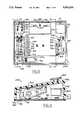
- FIGS. 1A, 1B and 2show a microsurgical control system 40 provided with an illumination lamp drawer 41, an electronic control system housed in part in a nine-board electronic card rack 42, and a pneumatic control system 43 housed primarily in a pneumatic drawer module 44, and other modules which will be described later.
- the control system 40includes a system console 46 which has an upwardly and slightly inwardly-sloping front surface 47 with a primary front panel 48.
- On the front panel 48is an electronic display screen 50, a plurality of pushbuttons or touch sensitive pads 52 organized in two groups 54 and 56 along the left and right sides of the display screen 50, and a third group 58 along the bottom of the display screen 50.
- the console 46also includes a slot 70 for a conventional Storz aspirant collection cassette 72, a cassette eject button 74 and an irrigation pinch valve assembly 76.
- the electronic display screen 50is controlled by a microcomputer within the console 46 to provide several different menus or messages which instruct the operator as to the function of the pushbuttons 52 through 62.
- the operation of the display screen 50 in combination with the buttons 52-62may be best understood by looking at the enlarged view in FIG. 2.
- the display screen 50is shown there as being conceptually divided into central display screen region 82, left-side display region 84, right-side display region 86, bottom display region 88 and a top display region 90.
- the side regions 84 and 86each consist of six horizontal fields stacked one above the other and positioned to correspond to the locations of buttons in button groups 54 and 56.
- buttons 58a-1 and 58a-2are similarly paired. This arrangement allows the indicated function of each of the buttons 54 or 56 to be readily changed by simply just changing the legend displayed in its adjacent field.
- each pair of buttonssuch as buttons 58a-1 and 58a-2, is associated with one of the three-part fields of bottom region 88, such as region 88a.
- buttons 58a-1 through 58e-1are used to increment a setting or parameter displayed in the corresponding region 88a- 88e of screen 50 directly above, while the buttons in the lower row, i.e., buttons 58a-2 through 58e-2, are used to decrement such displayed settings or parameters.
- the use of an electronic display screenalso permits the legends for buttons 52, 54 and 56 to be labeled in virtually any language.
- Button 58fis used to bring up an information screen on display 50 to assist the operator, such as by further explaining functions associated with choices on the display menu.
- Button 58gis used to return to an earlier menu screen in a chain of related menus or other screens.
- the microsurgical control system 40is capable of operating a number of different microsurgical instruments. To provide for this functionality, there is a row of different types of connector receptacles on surgical instrument connector panel 90 which permits various instruments to be plugged in or otherwise controlled by the control system 40 as may be seen in FIGS. 1A and 2, indicator lights are provided adjacent to or above each of the connector receptacles for indicating when the connector is activated or functional.
- FIG. 1Ashows a fiber-optic illumination instrument 100 coupled to console 46 via fiber-optic cable 102 which extends out of male illumination connector plug 104 designed for insertion into illumination connector receptacle 106.
- Indicator lamp 108is illuminated whenever the fiber optic illumination (FOL) lamp inside console 46 is lit.
- Phaco fragmentation handpiece 110is a conventional piezoelectric device for disintegrating hard objects such as intraocular cataractous material utilizing ultrasonic ("US") energy transmitted to its needle III. Electrical power pulsating at US frequency is provided to handpiece 110 via power cable 112 attached to phaco connector plug 114, which is designed to be inserted into phaco female connector 116. Light 118 indicates when US frequency electrical power is being delivered to 116.
- USultrasonic
- Female connector 120is designed to receive a male connector plug (now shown) for powering a conventional bipolar coagulator handpiece. Indicator light 122 indicates when this connector 120 is operational.
- Female connector 126is used for receiving a male connector plug (not shown) of a conventional CAC handpiece. (GAC stands for "controlled anterior capsulotomy.")
- Indicator 128illuminates when the CAC function is activated.
- Certain microsurgical instrumentsare actuated or controlled by fluid pressure (either positive pressure or negative pressure, or both).
- the phaco fragmentation instrument 110for example, utilizes aspiration through hollow flexible plastic tubing 138 to remove disintegrated materials, which are collected along with aspirant in the cassette 72.
- Vitrectomy probe 140includes a hollow needle 141 having an inner tube which reciprocates to cut intraocular material sucked in a small hole near the tip of the needle.
- the inner tube(not shown) reciprocates on account of pulsating air pneumatic drive signal delivered to a spring-returned piston (not shown) to which the inner tube is connected.
- the suction part of this instrumentis also coupled to the collection container 72 by tubing 142.
- Bracket 143is intended to indicate that either tube 142 or tube 138 may be connected to the remaining portion of tube 144 which leads to the collection cassette 72.
- Tubing 144 extending from the probe 140leads to male connector plug 145 which is inserted into vitrectomy connector receptacle 146. Light 148 indicates when the connector is activated.
- Connector 146supplies the pulsating air drive signal to the vitrectomy probe from a pneumatic circuit which will later be described.
- a conventional vitrectomy probe in the form of a guillotine cuttersuch as the Storz MICROVIT® probe may be used.
- the improved probe described in aforementioned U.S. patent application Ser. No. 428,125, filed Oct. 27, 1989 entitled “Vitrectomy Probe”may be used as probe 140.
- Connector receptacle 150provides access to an intraocular pressure (IOP) system (not shown), and indicator light 152 indicates when connector 150 is actuated.
- Connector 156is used to deliver a pneumatic drive signal to conventional pneumatically operated microscissors (not shown), which can be operated in any one of three modes as will be further explained.
- Indicator light 158is illuminated when any one of the three scissors modes is enabled.
- microsurgical instrumentsWhile certain microsurgical instruments have been illustrated or described in connection with FIG. 1A, it should be understood that the microsurgical control system 40 can be used with other instruments of a similar type. In general, any microsurgical instrument that is actuated or controlled by fluid pressure (whether positive or negative), can be made to operate with the pneumatic control system of the present invention.
- the irrigation pinch valve assembly 76is utilized to provide on/off control for the gravity-infused salt solution held in the IV bottle.
- the pinch valveis operated by an on/off solenoid of the pneumatic system as will be further explained.
- Display 66which may be an LED display or the like, indicates the height of the IV pole above the minimum reference height established via the zero switch 62e.
- a removable memory key 132is provided for this purpose.
- the key 132includes an integrated memory circuit which stores such operating values or set-up parameters.
- Console 46receives the key 132 through a key receptacle interface 134 mounted in plate 136. Suitable types of memory keys and receptacle interfaces are commercially manufactured by Datakey, Inc. of Burnsville, Minn. However, it should be appreciated that other suitable means for storing particular user data may be employed with the console 46 as well, such as electronic cards with memory, magnetic disk media, or the like.
- panel 60is used to control a motorized IV pole (not shown) that supports one or more bottles or pouches of balanced salt solution used to provide irrigation during ophthalmic surgical procedures.
- the motorized IV poleincludes a reversible electric motor/gear reducer combination which adjusts the height of the IV pole up or down as desired. The particular height may be selected via the buttons on control panel 60. Buttons 62a and 62b are used to lower and raise the pole incrementally, as long as the button is held. Button 62c is used, under emergency conditions, to send the pole upward rapidly to its maximum height, and indicator emblem 64 is illuminated when this function is activated.
- Button 62dwhen depressed, automatically lowers the IV pole to a convenient height to facilitate changing of the IV bottle.
- Button 62eis called the "zero switch” because when pressed it establishes the zero reference, i.e., the minimum height for the IV pole.
- Button 62f and 62gare used respectively to change the height for the IV pole to either a first or second preset level.
- Button 62his used during set-up to specify the first and second preset heights of the IV pole.
- FIG. 1Bshows the rear of the system console 46, including the rear surface 166.
- the console 46includes a base frame or chassis 168, a sheet metal cover 170 having three sides forming an inverted U-shape, and back cover plate 172 occupying roughly the top two-thirds of the surface 166.
- the bottom one-third of the rear surface 166is occupied by the rear wall 174 of pneumatic drawer module 44 shown in phantom, and the rear wall 176 of electrical power drawer 178 which is also partially shown in phantom and will be later described.
- Rear cover plate 172includes a set 202 of 24 ventilation louvers arranged in three columns.
- Rear wall 176 of power electrical drawer 178includes a set 206 of eight ventilation louvers arranged as shown. Both sets 202 and 206 of louvers allow air to be drawn inside of the console 46.
- Air drawn in through louvers 202circulates internally and eventually exits at exhaust fan 184, while air drawn in through louvers 206 is substantially confined to circulate within the electrical drawer 208 and past the lamp drawer 41 since it is confined by shelf/cover 208 and plenum 212 to be exhausted by ventilation fan 182.
- the main pneumatics supply connection to pneumatics drawer 44is made through a male Schrader quick-disconnect fitting 214 in the lower left rear corner of rear wall 174. Electrical power is provided to the electrical drawer module 178 via electrical receptacle and fuse holder assembly 218. A main on/off electrical power switch 220 for turning the console 46 on or off, is located above receptacle 218.
- the various hardware assemblies and drawers of console 46are constructed in a highly modular, easy-to-assemble and easy-to-service manner described in detail in aforementioned U.S.
- the control console 46is the heart and brain of the multi-function microsurgical system 40.
- the system 40supports up to nine switch-selectable modes which are used in either or both anterior segment and posterior segment ophthalmic surgery. These modes are: (1) irrigation only, (2) irrigation/aspiration, (3) phaco (either emulsification or fragmentation), (4) vitrectomy, (5) controlled anterior capsulotomy (CAC), (6) bipolar, (7) scissors, (8) illumination, and (9) intraocular pressure (IOP) control.
- Each modeis automatically integrated into the system 40 in a manner appropriate to the type of operation selected by the operator via keys 52-58.
- Irrigation modeemploys a footpedal on/off control of irrigation.
- This operating modeis intended for use during an anterior capsulotomy and other anterior segment procedures in which irrigation without aspiration is desired.
- Irrigation/aspiration modeprovides footpedal on/off control over irrigation and linear footpedal control over aspiration. This mode is intended for use in the engagement, stripping and removing of residual lens cortical material in extracapsular cataract extraction and phacoemulsification procedures.
- Phaco modeimplements the phacoemulsification and phacofragmentation functions, which are available for both anterior and posterior segment procedures.
- a "fixed phaco" modeis available in which the phaco power and aspiration levels are set via the console controls
- linear phacois available in which phaco power is footpedal controlled and aspiration level is determined by the console controls.
- a fixed phaco modecontrols aspiration via the footpedal.
- Vitrectomy modemakes the vitrectomy function is available for both anterior and posterior segment procedures. For anterior vitrectomy, footpedal on/off control is provided for vitreous cutting and irrigation, while linear footpedal control is provided for aspiration. For posterior vitrectomy, this mode provides footpedal/on-off control over vitreous cutting and linear footpedal control over aspiration. 5.
- CAC modeprovides footswitch on/off control of a CAC probe, and is explained further in connection with the discussion FIG. 4D below.
- Bipolar modeprovides on/off control of bipolar power via the footpedal assembly, and is described further in the discussion of FIG. 4D below.
- Scissors modeenables the posterior surgeon to employ a pneumatically driven intraocular scissors in any one of three foot-pedal controlled cutting operations: single cut, variable rate or proportional, which will be explained in more detail later.
- Illumination modeprovides fiber-optic illumination to facilitate viewing the posterior segment during posterior procedures. The light source thereof is adjustable from approximately five-percent illumination to full brilliance. Automatic lamp switching provides back-up illumination if the primary lamp should fail.
- IOP modeprovides precision regulated console-adjusted delivery of filtered air to the eye during posterior ocular pressure procedures. Alternatively this mode can be used to pressurize an irrigation supply to the eye for anterior procedures.
- console 46uses a disposable transparent cassette to collect aspirant during surgery. When the cassette is fully inserted into the cutout slot 70 in the console 46, the system 40 will automatically secure the cassette via a solenoid-actuated valve, and a vacuum connection will be established at that time. 10. Additional Surgical Features.
- the system 40also includes additional features, namely, aspiration prime and irrigation prime in the same manner implemented in the DAISY ophthalmic system.
- the special repeat reflux procedureis supported by the control console 46 in order to allow a handpiece to be cleared with pneumatic pressure if it becomes clogged with tissue. This reflux feature is available in all anterior modes, and consists of repeated reflux action.
- microprocessor-based control systemdescribed in FIG. 4, enables the various strategies for the control functions to be stored in memory and called upon as required.
- the various components of the surgical systemhave been constructed as separate modules or subassemblies where possible. This approach is evident in the electronics portion and pneumatics portion of the control system 40. Where practical, distinct electrical functions have been placed on their own printed circuit board which is separately addressed by the microprocessor. Similarly, the pneumatics functions have been collected and placed in one drawer module to allow easy installation and replacement.
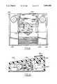
- FIG. 3(FIG. 3)
- FIG. 3shows a plan view of foot controller 240 (also called a footswitch assembly) utilized by the system 40 which has a metal carrying handle 241 and is linked directly to the console 46 with a suitable length of multi-conductor electrical cable 242 which has suitable multi-pin connector 244 at the end thereof that plugs into connector receptacle 190 on the back of the console 46.
- foot controller 240also called a footswitch assembly
- the footswitch assembly 240includes: a large plastic molded housing 246 enclosed with a large rectangular bottom plate 248; having a footpedal 250 which pivots about a horizontal footpedal shaft 252 supported by sintered bronze flange bushing assemblies 254 and 256; left and right vertically arranged side pedals 258 and 260; and left and right top footswitch assemblies 262 and 264 having mushroom heads 266 and 268 and electrical contact blocks 270 and 272, shown in phantom, to signal when the respective top buttons have been pushed.
- Side switches 278 and 280which may be microswitches or magnetic proximity switches, shown in phantom, are actuated and provide electrical signals indicating when their respective side pedals 258 or 260 have been pressed.
- the housing 246includes left and right bunker structures 282 and 284 which rise above footpedal 250 upon which top footswitches 262 and 264 are mounted.
- Underneath left bunker 282is located a footpedal position encoder assembly 286 shown schematically in phantom. Assembly 286 includes an optical position encoder 288 which produces two digital signals in a quadrature relationship as the shaft 252 rotates, and a zero reset switch 290.
- Under bunker 284is located a detent assembly 294 which may be electrically engaged as desired via detent control solenoid assembly 296 including an electrical solenoid coil 298.
- the side switches 278 and 280 and top footswitches 266 and 268provide on-off control of certain features during selected ophthalmic procedures.
- the left top footswitch 266provides on/off control of bipolar coagulation.
- the right top footswitch 268, via display 50 and buttons 52,may be configured to control the emergency rapid-up feature of the motorized IV pole option or to control some other operating room device via the accessory receptacle 194 on the back cover 166 of console 46.
- the footpedalis used to control irrigation, aspiration, phaco and vitrectomy modes in a manner like that used for the Storz DAISY console.
- the footpedal detentsare new and are provided in the manner described below to provide the surgeon with tactile feedback regarding the footpedal position.
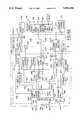
- FIG. 4(FIG. 4)
- FIG. 4Ashows a simplified block diagram of a microprocessor-based electronic control system 320 found in the control console 46 shown in FIG. 1.
- Control system 320includes a microcomputer 322 having a microprocessor 24, volatile (RAM) memory 325, nonvolatile (ROM) memory 326, a VME bus interface circuit or port 328, an interrupt handling circuit or port 330, and an internal control/address/data bus 332 which allows internal communications in conventional fashion between all portions of microcomputer 322.
- a preferred microprocessor 324is a 68000 Series Motorola microprocessor with a clock speed of 12.5 Megahertz and one wait state for handling interrupts, although any other suitable microprocessor could be used.
- Computer 322also includes a 25 Megahertz crystal oscillator 334, a watchdog timer circuit 336, and a chip select and addressing (CSA) section 338.
- the microcomputer 322is located on a single board, called the processor board.
- the microcomputer 322which is located on its own printed circuit (PC) board, communicates with the remainder of the electronic control system 320 via a VME bus 340 consisting of address, data and control lines 342, 343 and 344.
- the VME bus 340is used to communicate with seven other boards within the system 320, namely: the expansion memory PC board 345, the video control PC board 346 which drives the visual display 50, the CAC/bipolar circuit PC board 347, the phaco circuit PC board 348, the lamp control PC board 349, the pneumatic control PC board 350, and the expansion I/O PC board 352.
- the groupings of various functions on distinct PC boardswas done in order to make maintenance simpler. By clustering similar or related functions together on one board, it is possible to reduce diagnostic time and service costs since individual functions not performing correctly may be isolated on a board-by-board basis, and suspect boards may be replaced as needed.
- the processor board 322, the expansion memory board 345 and the video board 346are all conventional purchased items from PEP Modular Computers GmbH of Kaufbeuren, West Germany. The manner in which all of these boards are designed and work from a hardware and operating system perspective is conventional. The manner in which the video board 346 drives the CRT 50 is conventional too.
- the CRT 50 used with the control console 46is preferably a 9-inch diagonal monochrome monitor with standard resolution, although any other suitable two-dimensional display may be utilized such as liquid crystal display or electro luminescent display.
- the lamp control board 349is used to control the components in the lamp drawer 41 which is the source of light for fiber optic light pipe 100 shown in FIG. 1A.
- Pneumatic control board 350is used to control the cassette hardware 356 and the pneumatic drawer hardware 360.
- the cassette hardware 356refers to those input devices such as switches and output devices such as solenoids associated with the aspirant collection cassette 72 shown in FIG. 1A.
- the pneumatic hardwareincludes pressure transducer, a torque motor servo-valve and solenoids.
- Expansion I/O board 352is used to communicate or control the memory key circuit 362, the audio generator circuit 364, which drives speaker 366, the IV pole hardware 368, an optional remote controller 370, and the footpedal assembly 240 of FIG. 3.
- the expansion I/O board 352also is used to interrogate or operate various other input and output devices associated with the control console 46, such as the keypads 52, the indicator lights on secondary panel 60 and connector panel 90 and the accessory relay 372 associated with accessory receptacle 194 shown in FIG. 1A. All user-generated input commands are handled through I/O board 352.
- board 352To ensure such commands are promptly communicated to the processor 324, board 352 generates an interrupt request (IRQ) signal on line 374 to inform the processor 324 that the I/O board needs to be serviced.
- the processoralso generates an interrupt acknowledge (IRA) signal on line 376.
- IRQinterrupt request
- IRAinterrupt acknowledge
- FIG. 4Bshows a detailed block diagram of the I/O expansion board 352 and the devices which it drives or reads, namely: the indicator lights on secondary front panel 60 and on connector panel 90 (represented by block 620) and relay 372 for accessory connector 194, the speaker 366, and the primary and secondary front panel buttons 52 and 62, all of which are located in or on the control console 46 (indicated by these devices being to the left of the dashed line 46, which represents the perimeter of control console 46).
- the board 352also drives and/or reads devices in the motorized IV pole assembly 368, the footpedal assembly 240, and the optional remote control console 370, which are all outside of the control enclosure 46.
- the I/O board 352communicates with the VME bus 340 through a VME interface 390f which includes tri-state buffer circuits 626, address and control decoder circuit 628 and 16-bit data latch or register 630.
- the I/O circuitry on board 352also includes four primary control interface circuits, namely accessory control 630, memory key control 632 for memory key 132, audio control 634 for speaker 366, and footpedal control 636.
- Control circuit 636in turn directs the operation of two slave circuits, namely detent control 638 and footpedal decoder 640 which actually communicate with devices in footpedal assembly 240.
- Board 352also includes a conventional serial communications interface circuit 644 which drives and reads in conventional fashion an interrupt generator circuit 645 and a non-volatile memory 646, which preferably is an electrically erasable programmable read only memory (EEPROM).
- Circuit 644includes three conventional integrated circuit (IC) chips, namely a dual universal asynchronous receiver/transmitter (DUART) 647, a dual-channel RS-422 transmitter chip 648, and a dual-channel RS-422 receiver chip 649, all functionally connected as shown in FIG. 4F.
- ICintegrated circuit
- the primary interface circuits 630.638 and the serial communications interface 644communicate with VME bus interface 390f via control signals passed along dedicated control lines 650-656 and 664. Data to be sent to and/or received from circuits 630-638 or communications interface 644 is passed along an internal 16-line data bus 666 connected to data latch 630. Footpedal control 636 communicates with slave circuits 638 and 640 via lines 668 and 670. Each of the primary control circuits and the communications interface 644 contains a data latch circuit for receiving, holding and/or transmitting data to internal data bus 666.
- Address and control decoder 628upon receipt of commands from processor 324 via VME bus 340, decodes the command and address signals on lines 342 and 343, and in accordance with the decoded instructions distributes the desired control signals and/or via lines 667 commands data signals to the control interface circuit 630-636 or 644 which the processor 324 desires to address.
- the control interface circuits 630-636have no intelligence and do not on their own seek to communicate with processor 324. Instead, processor 324 just periodically writes or reads data to these control circuits.
- the communications interface 644has two devices connected to it which have intelligence, namely microcontroller 672 associated with the two front panels 48 and 60 on console 46 and microcontroller 674 associated with optional remote controller 370.
- Serial communications interface 644converses with the microcontrollers 672 and 674 using the well-known RS-422 communications protocol at a suitable data rate, such as 9600 baud. Whenever either of these two microcontrollers has information to be sent to processor 324, it serially sends a byte of information to the communications interface 644 which in turn automatically causes an interrupt to be generated.
- Communications interface 644is identified as the source of the interrupt, the interrupt is acknowledged via line 376, and the processor 324 causes data serially communicated to the DUART 647 by the microcontroller to be loaded into the data latch 630, and then via VME bus 340 reads the data from latch 630 in one of its next I/O cycles.
- Microcontroller 672has its own internal oscillator and micro program. It continuously monitors all of the buttons 52 and 62 found on front panels 48 and 60 of the control console 46 to determine whether they have been depressed. The buttons are electrically arranged in a matrix of row and columns, and by interrogating each position of the matrix the state of all the buttons is determined.
- the microcontrolleradvises the processor whenever a button is pressed, and keeps periodically advising the processor 324 of this fact for as long as the button remains pressed.
- Microcontroller 672also monitors, as part of the aforementioned matrix of buttons, the status of top buttons 270 and 272 and side pedals switches 278 and 280 within the footpedal assembly.
- the microcontrollers 672 and 674are provided in order to ensure that the main processor 324 is apprised of changes in status at the front panel console or remote control console virtually immediately for a very quick response to operator requests. In other words, all the routine functions which need not be performed quickly by the main processor 324 are made to wait while processor 324 responds to an interrupt and reads the data from the microcontroller and puts it into a table in main memory 325 one byte at a time. In main memory, a table listing the states of all the buttons on the main console and the remote control console is kept. The microcontrollers 672 and 674 only advise the main processor 324 of changes in the state of any of the buttons. In this manner, communications between the microcontrollers 672 and 674 are handled far more efficiently than updating the entire table each time an interrupt is generated.
- Microcontroller 674operates in the same manner as microcontroller with respect to the matrix of buttons it monitors.
- the remote control console 370also contains a keyboard interface circuit almost identical to interface circuit 680. This interface circuit is described in detail in aforementioned U.S. patent application Ser. No. 427,614, filed Oct. 27, 1989, entitled "Remote Control Console For Surgical Control System.”
- Communications interface 644also reads and writes data to EEPROM 646 in conventional fashion.
- EEPROM 646is provided so console 46 can store, in a non-volatile manner, any user-programmed default values, configuration codes, calibration data and/or any other pertinent parameters which may be entered in by the user.
- the accessory control 630contains: a plurality of memory latches and indicator light driver circuits dedicated to driving the indicator lights 620 on connector panel 90 and secondary panel 60., a plurality of memory latches, relay driver circuits, sensing circuits and an optical position decoder, all of which are dedicated to sending control signals to and receiving information from motorized IV pole hardware 368; and a latch and relay driver for operating relay 372.
- a relay driving signalis applied to line 652
- relay coil 372is energized, which closes a normally open contact and thus completes the circuit available on lines 664 connected to the connector receptacle 194 shown in FIG. 1B.
- the details of the electrical devices and circuits in the motorized IV pole 368are described in U.S.
- the audio control circuit 634is of standard design, and uses a conventional programmable sound generation circuit on a large scale integration (LSI) chip to produce the various tones at various amplitudes used to indicate device operation and provide audio error signals to the console user.
- the output signal from this chipdrives a separate conventional low-power audio amplifier chip, whose output is connected to and drives speaker 366.
- a suitable sound generatoris available from Microchip Technology, Inc. of Chandler, Ariz. as Model No. AY8930.
- One of the unique features provided by control console 46is the user of select various tones and amplitudes for the selected tones to represent different conditions or states that the control system 40 may be placed in by the surgeon. A further description of this aspect of the control system 40 is provided in aforementioned U.S.
- the detent control 638provides positive and negative 24 volt DC power signals on lines 668 to operate the detent solenoid 296.
- a momentary -24 VDC signalextends the armature of solenoid 296 while a momentary -24 VDC signal causes it to retract.
- Conventional magnetic and/or mechanical detents built into solenoid 296hold its armature in the last position the signals on lines 668 placed it in.
- Footpedal decoder 640receives low-voltage quadrature signals over conductors 680 from encoder 288, and a low-voltage digital signal on line 682 from zero switch 290. Switch 290 is released whenever footpedal 250 is moved more than two degrees from its spring-returned position, that is, the position pedal 250 is in when it is not pressed at all.
- bi-directional multiple stage digital counter 684 within decoder circuit 640is held in a reset state. As soon as signal 682 goes to its opposite state, counter 684 is allowed to operate under the control of the quadrature signals on lines 680 which increment or decrement the counter with each pulse.
- the accumulated count in counter 684reflects the true angular position of footpedal 250.
- Processor 324periodically (once every 50 milliseconds) reads the value in counter 684 by sending appropriate control signals to bus interface 390f so that counter 684 can send its present count to data bus 666, where it is held by latch 630 until read by the processor 324 via VME bus 340.
- top button switches 270 and 272 and the side pedal proximity switches 278 and 280 of the footpedal assembly 240are also read through microcontroller 672, which as previously explained serially transmits information to communications interface 644, through internal bus 666, bus interface 390f and VME bus 340 to processor 324.
- the footswitch assembly 240includes switch function legends 712 and 714 which are shown in more detail in FIGS. 6 and 7.
- Switch legends 712 and 714indicate schematically the various functions associated with the left and right top footswitch assemblies 262 and 264, the side pedals 258 and 260, and the footpedal 250. Functions used in the anterior mode are illustrated in FIG. 6 and functions used in the posterior mode are illustrated in FIG. 7.
- footpedal shaft 252is coupled to the encoder 288 by means of a 48 tooth timing belt pulley 700 attached to the footpedal shaft 252, and an 18 tooth timing belt pulley 702 attached to an encoder shaft 704.
- the 48 tooth timing belt pulley 700 and the 18 tooth timing belt pulley 702are coupled with a Kevlar reinforced neoprene timing belt 706.
- the two timing belt pulleys 700 and 702have side faces to ensure that the timing belt remains in place.
- Zero reset switch 290is engaged by an eccentric lobe 708, best seen in FIG. 10, attached to the encoder shaft 704 by means of two set screws.
- a pin 710extends at right angles from the end of the eccentric lobe 708 to contact the reset switch 290.
- eccentric lobe 708will move sufficiently to release zero reset switch 290, and encoder 288 will begin to count.
- zero reset switch 290will be depressed again by lobe 708 and the encoder 288 count is reset to zero.
- Zero reset switch 290is a normally closed contact so that it does not close until the eccentric lobe 708 comes off the switch 290 upon pressing of the footpedal.
- the encoder 288is made by Hewlett-Packard which is used with a 4 ⁇ decoding chip which yields 2,048 counts per revolution.
- the full range of travel of the footpedal 250is on the order of 20 degrees to 22 degrees. This is translated to approximately 60 degree travel on the encoder shaft 74 by means of the 48 tooth gear 700 and the 18 tooth gear 702 as described above.
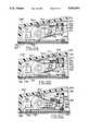
- footpedal shaft 252is attached to spring detent shaft 716 by means of a roll pin (not shown) passed through a hole drilled into the near end of the detent shaft 716.
- Detent shaft 716is preferably a solid carbon-steel rod.
- the spring-detent assembly 294includes five detent plates including a first, second, third, fourth and fifth detent plate, 718, 720, 722, 724, and 726 respectively.
- the five detent plates 718-726are spaced parallel to one another axially along the detent shaft 716.
- the central, or third, plate 722is welded to the detent shaft 716, while the other four detent plates are free to rotate upon ball bearings (not shown).
- Solenoid assembly 296engages with outer detent plate 718 as follows.
- Detent plate 718has a stop lever 732 extending outwardly therefrom, which contacts a roll pin 734 extending from a solenoid frame 736. Since the pin 734 and solenoid frame 736 are stationary with respect to the housing 246, the point at which stop lever 732 contacts pin 734 will determine the full-up stop position of the detent assembly 294.
- Solenoid assembly 296includes a solenoid shaft 738 which reciprocates through an opening in the solenoid frame 736 when the solenoid is energized to its extended position. As seen in FIG. 11, when solenoid shaft 738 is in the extended position, stop lever 732 of the first detent plate 718 is captured between the roll pin 734 and the solenoid shaft 738.
- the detent assemblies 294When the solenoid shaft 738 is in the retracted position, the detent assemblies 294 has only one spring rate, called the first spring rate.
- the first spring rateis determined by two parallel extending springs 740 and 742 connected to pins 744 and 746 extending perpendicularly from either side of the center detent plate 722. The other end of springs 740 and 742 are fastened to a spring bracket 748 which is fastened to the footswitch housing 246.
- FIG. 13Ashows the detent assembly 294 in the pedal-up position
- FIG. 13Bshows the pedal-down position, both with the detent 738 retracted.
- solenoid shaft 738When solenoid shaft 738 is in a retracted position, all five plates 718-726 move together synchronously when footpedal 250 is pressed. Thus the only resistance is by springs 740 and 742. Springs 740 and 742 are selected to achieve approximately a six pound force upon full depression of the footswitch pedal 250.
- the following structureis employed.
- On the end of the second 720, third 722 and fourth 724 detent platesare blocks 750, 752 and 754 respectively, having a threaded hole through which threaded adjustment screws 756, 758 and 760, are run.
- These adjustment screws 756-760are turned with an allen wrench, but other conventional mechanisms may be used if desired.
- the center plate adjustment screw 758is used to adjust the pedal height in the at-rest position, which effectively determines the total number of counts from the encoder 286 through the full length of footswitch travel. This is factory set in order to have a uniform number of counts with each footswitch assembly 240 manufactured.
- the second 720 and fourth 724 detent platesare used in conjunction with second and third rate springs 762 and 764 respectively.
- the adjustment screws 756 and 760 associated with the second 720 and fourth 724 detent platesdetermines the point at which additional spring load connected to its detent plates becomes operational when the footswitch is in the detent mode.
- Springs 762 and 764are connected to a spring shaft 766 which extends perpendicularly to the outer detent plates 718 and 726.
- the spring shaft 766 and the adjustment block 730 extending between the outer detent plateseffectively cause the outer detent plates 718 and 726 to be a solid structure which rotates in unison and has a rigid frame.
- lobes 768 and 770having a hole therein to which the second and third rate spring 762 and 764 respectively are connected.
- these springsextend between the spring shaft 766 adjacent the detent shaft 738 and the lobe 768, 770 at the outer end of the detent plates 720 and 724.
- the center detent plate 722has a pin 772 extending outwardly through centrally located holes 774 and 776 in the second and fourth detent plates 720 and 724.
- This pin 772 in the center detent plate 722may be called the pickup pin since as the center detent plate rotates, the pickup pin 722 contacts first the second detent plate 720 and then later the fourth detent plate 724 to kick in the second and third spring rates respectively.
- the size of the hole 774, in combination with the setting of the adjustment screw 756 for the second detent plate 720determines when it kicks in.
- the size of the hole 776 and the setting of the adjustment screw 760determines when the fourth detent plate 724 kicks in.
- spring 762 or 764may be used as the second or third spring rate; however, in the preferred embodiment the second detent plate 720 is used in conjunction with the second spring 762 for the second spring rate as a matter of convention.
- the cumulative spring load now felt by the footpedal assembly 240is determined by the first, second and third rate springs 740, 742. 762 and 764.
- the pedal assembly 240includes sidepedals 258 and 260 located on the left and right sides of the main pedal 250.
- a horizontal U-shaped bracket 778which has shoulder screws 780 that are driven in by an allen wrench to the U-shaped bracket 778.
- the shoulder screws 780are approximately one-quarter inch in diameter and have a three-eights inch smooth cylindrical shoulder portion, and a three-sixteenths inch threaded portion which is turned into a threaded hole in the bracket 778.
- the shoulder of the shoulder screw 780holds down a hinge block 782 to which the sidepedals 258 and 260 are mounted by two machine screws 784.
- a return spring 786extends between the two sidepedals 260 and 258 with a semi-circular hook at the end of the spring being passed through corresponding holes and slots in the sidepedals 258, 260.
- the sidepedals 258 and 260are only used in an on-off manner.
- a conventional hinge pin 779may be used to provide hinging action.
- Actuations of the sidepedals 258, 260is determined by waterproof microswitches 788, which are mounted at the upper left and right hand sides of the U-shaped bracket 778.
- the microswitches 788are attached to conductors 790, seen in FIG. 9, and are potted. Conventional potting compound is used to seal the wires 790 in this opening.
- a wiring cavity 794to which various wires are bundled and connected to a conventional cable feedthrough assembly 796.
- a 15-wire cable 242, shown in FIG. 3,is approximately 12 feet long and is connected to this feedthrough 796.
- the feedthrough 796is also watertight.
- the particular connector 796 usedis made by AMP and is a 14-pin connector, with the 15th wire in the cable being a spare.
- the sidepedals 258, 260are stopped from further movement by the left and right bunker structures 282 and 284 which are approximately two inches wide and nine inches long and two and one-half inches high. Near the upper corner of each bunker structure 282 and 284 are the mushroom heads 266 and 268 of the left and right top foot switch assemblies 262 and 264, as shown in FIG. 8. Foot switch assemblies 262 and 264 are conventional Furnace brand, oiltight industrial duty pushbutton switches. The top right foot switch 264 is used to turn on and off auxiliary accessories as indicated in FIGS. 6 and 7. The left foot switch assembly 262 is used to turn off and on the bipolar cautery function. As shown in FIGS.
- these pushbutton switches 262 and 264have the same function in both the anterior segment and posterior segment modes of operation of the console.
- the sidepedals 258 and 260are used differently depending on whether in the anterior or posterior mode of operation. In the anterior mode, as shown in FIG. 6 the left sidepedal 258 is used to control reflux, while the right sidepedal is used to control the cutter space CAC (controlled anterior capsulotomy) function. In the posterior mode, as shown in FIG. 7, the left sidepedal 258 is used to turn the MICROVIT® cutter off, while the right sidepedal is used to turn the MICROVIT® cutter on. In the fragmentation mode, the right sidepedal is used to turn the fragmentation on and off.
- the footswitch assemblymay employ fewer or greater than three spring rates, or, a non-optical position encoder may be used.
- the footswitchmay be used for non-ophthalmological surgical instruments.
- the footswitch assemblymay be employed for other types of nonsurgical instruments. Accordingly, it is to be understood that the protection sought and to be afforded hereby should be deemed to extend to the subject matter defined by the appended claims, including all fair equivalents thereof.
Landscapes
- Health & Medical Sciences (AREA)
- Engineering & Computer Science (AREA)
- General Physics & Mathematics (AREA)
- Automation & Control Theory (AREA)
- Physics & Mathematics (AREA)
- Oral & Maxillofacial Surgery (AREA)
- Water Supply & Treatment (AREA)
- Dentistry (AREA)
- Epidemiology (AREA)
- Life Sciences & Earth Sciences (AREA)
- Animal Behavior & Ethology (AREA)
- General Health & Medical Sciences (AREA)
- Public Health (AREA)
- Veterinary Medicine (AREA)
- Surgical Instruments (AREA)
Abstract
Description
Claims (15)
Priority Applications (1)
| Application Number | Priority Date | Filing Date | Title |
|---|---|---|---|
| US07/428,355US5091656A (en) | 1989-10-27 | 1989-10-27 | Footswitch assembly with electrically engaged detents |
Applications Claiming Priority (1)
| Application Number | Priority Date | Filing Date | Title |
|---|---|---|---|
| US07/428,355US5091656A (en) | 1989-10-27 | 1989-10-27 | Footswitch assembly with electrically engaged detents |
Publications (1)
| Publication Number | Publication Date |
|---|---|
| US5091656Atrue US5091656A (en) | 1992-02-25 |
Family
ID=23698541
Family Applications (1)
| Application Number | Title | Priority Date | Filing Date |
|---|---|---|---|
| US07/428,355Expired - LifetimeUS5091656A (en) | 1989-10-27 | 1989-10-27 | Footswitch assembly with electrically engaged detents |
Country Status (1)
| Country | Link |
|---|---|
| US (1) | US5091656A (en) |
Cited By (125)
| Publication number | Priority date | Publication date | Assignee | Title |
|---|---|---|---|---|
| US5249121A (en)* | 1989-10-27 | 1993-09-28 | American Cyanamid Company | Remote control console for surgical control system |
| US5268624A (en)* | 1992-10-14 | 1993-12-07 | Allergan, Inc. | Foot pedal control with user-selectable operational ranges |
| US5422521A (en)* | 1993-11-18 | 1995-06-06 | Liebel-Flarsheim Co. | Foot operated control system for a multi-function device |
| US5549139A (en)* | 1989-10-27 | 1996-08-27 | Storz Instrument Company | Pneumatic controls for ophthalmic surgical system |
| US5554894A (en)* | 1994-10-28 | 1996-09-10 | Iolab Corporation | Electronic footswitch for ophthalmic surgery |
| US5635777A (en)* | 1995-12-28 | 1997-06-03 | Andrew Telymonde | Foot operated control apparatus |
| USD388056S (en)* | 1995-09-29 | 1997-12-23 | Liebel-Flarsheim Company | Actuator for foot-operated control system |
| WO1998008450A1 (en)* | 1996-08-29 | 1998-03-05 | Storz Instrument Company | Ophthalmic microsurgical system employing flash eeprom and reprogrammable modules |
| WO1998040022A1 (en)* | 1997-03-10 | 1998-09-17 | The University Of Iowa Research Foundation | Remote controlled coagulator system and methods |
| US5883615A (en)* | 1995-09-29 | 1999-03-16 | Liebel-Flarsheim Company | Foot-operated control system for a multi-function |
| US5910139A (en)* | 1996-08-29 | 1999-06-08 | Storz Instrument Co. | Numeric keypad simulated on touchscreen |
| US5983749A (en)* | 1997-09-12 | 1999-11-16 | Allergan Sales, Inc. | Dual position foot pedal for ophthalmic surgery apparatus |
| US5997528A (en)* | 1996-08-29 | 1999-12-07 | Bausch & Lomb Surgical, Inc. | Surgical system providing automatic reconfiguration |
| US6007550A (en)* | 1996-02-20 | 1999-12-28 | Computer Motion, Inc. | Method and apparatus for performing minimally invasive cardiac procedures |
| US6055458A (en)* | 1997-08-28 | 2000-04-25 | Bausch & Lomb Surgical, Inc. | Modes/surgical functions |
| US6086576A (en)* | 1996-08-29 | 2000-07-11 | Bausch & Lomb Surgical, Inc. | Automatically switching the termination of a communications bus |
| US6117126A (en)* | 1996-08-29 | 2000-09-12 | Bausch & Lomb Surgical, Inc. | Surgical module with independent microprocessor-based communication |
| US6150623A (en)* | 1998-08-27 | 2000-11-21 | Allergan | Back-flip medical footpedal |
| US6179829B1 (en)* | 1997-08-28 | 2001-01-30 | Bausch & Lomb Surgical, Inc. | Foot controller for microsurgical system |
| US6238389B1 (en) | 1997-09-30 | 2001-05-29 | Boston Scientific Corporation | Deflectable interstitial ablation device |
| US6251113B1 (en) | 1996-08-29 | 2001-06-26 | Bausch & Lomb Surgical, Inc. | Ophthalmic microsurgical system employing surgical module employing flash EEPROM and reprogrammable modules |
| WO2002001310A1 (en)* | 2000-06-27 | 2002-01-03 | Advanced Medical Optics, Inc. | Ribbon switch in surgical footpedal control |
| US6436107B1 (en) | 1996-02-20 | 2002-08-20 | Computer Motion, Inc. | Method and apparatus for performing minimally invasive surgical procedures |
| US6452120B1 (en) | 2000-05-11 | 2002-09-17 | Advanced Medical Optics | Dual dimensional shoe sensor and foot pedal operated switch for surgical control |
| US6463361B1 (en) | 1994-09-22 | 2002-10-08 | Computer Motion, Inc. | Speech interface for an automated endoscopic system |
| US20030191455A1 (en)* | 2001-05-01 | 2003-10-09 | Dan Sanchez | Pivot point arm for a robotic system used to perform a surgical procedure |
| US20030195663A1 (en)* | 2001-09-07 | 2003-10-16 | Yulun Wang | Modularity system for computer assisted surgery |
| US6639332B2 (en)* | 2001-12-19 | 2003-10-28 | Bausch & Lomb Incorporated | Foot controller with ophthalmic surgery interlock circuit and method |
| US6642836B1 (en) | 1996-08-06 | 2003-11-04 | Computer Motion, Inc. | General purpose distributed operating room control system |
| US6646541B1 (en) | 1996-06-24 | 2003-11-11 | Computer Motion, Inc. | General purpose distributed operating room control system |
| US6674030B2 (en)* | 2001-09-19 | 2004-01-06 | Advanced Medical Optics | Intelligent surgical footpedal with low noise, low resistance vibration feedback |
| US6689975B2 (en)* | 2001-12-19 | 2004-02-10 | Bausch & Lomb Incorporated | Foot controller including multiple switch arrangement with heel operated, door-type switch actuator |
| US20040035242A1 (en)* | 2002-08-26 | 2004-02-26 | Peterson Robert H. | Footswitch |
| US6699177B1 (en) | 1996-02-20 | 2004-03-02 | Computer Motion, Inc. | Method and apparatus for performing minimally invasive surgical procedures |
| US6714841B1 (en) | 1995-09-15 | 2004-03-30 | Computer Motion, Inc. | Head cursor control interface for an automated endoscope system for optimal positioning |
| US6726699B1 (en) | 2000-08-15 | 2004-04-27 | Computer Motion, Inc. | Instrument guide |
| US20040106915A1 (en)* | 2002-12-03 | 2004-06-03 | Thoe David A. | Foot controller for microsurgical system |
| US20040124964A1 (en)* | 1996-08-06 | 2004-07-01 | Computer Motion, Inc. | General purpose distributed operating room control system |
| US6793653B2 (en) | 2001-12-08 | 2004-09-21 | Computer Motion, Inc. | Multifunctional handle for a medical robotic system |
| US6804581B2 (en) | 1992-08-10 | 2004-10-12 | Computer Motion, Inc. | Automated endoscope system for optimal positioning |
| US20040236352A1 (en)* | 1997-09-22 | 2004-11-25 | Yulun Wang | Method and apparatus for performing minimally invasive cardiac procedures |
| US6839612B2 (en) | 2001-12-07 | 2005-01-04 | Institute Surgical, Inc. | Microwrist system for surgical procedures |
| US20050025646A1 (en)* | 2003-07-30 | 2005-02-03 | Vance Products Inc. D/B/A Cook Urological Incorporated | Foot pedal medical irrigation system |
| US6852107B2 (en) | 2002-01-16 | 2005-02-08 | Computer Motion, Inc. | Minimally invasive surgical training using robotics and tele-collaboration |
| US20050038416A1 (en)* | 2002-01-16 | 2005-02-17 | Computer Motion, Inc. | Minimally invasive surgical training using robotics and telecollaboration |
| US20050043717A1 (en)* | 1999-10-01 | 2005-02-24 | Computer Motion, Inc. | Heart stabilizer |
| US20050103607A1 (en)* | 2003-11-13 | 2005-05-19 | Mezhinsky Victor B. | Dual control footswitch assembly |
| US20050109595A1 (en)* | 2003-10-29 | 2005-05-26 | Mezhinsky Victor B. | Ergonomic footswitch |
| US6905491B1 (en) | 1996-02-20 | 2005-06-14 | Intuitive Surgical, Inc. | Apparatus for performing minimally invasive cardiac procedures with a robotic arm that has a passive joint and system which can decouple the robotic arm from the input device |
| WO2005060858A1 (en)* | 2003-12-18 | 2005-07-07 | Dentsply International Inc. | Integrated dental equipment |
| US20050147940A1 (en)* | 2004-01-07 | 2005-07-07 | Mace James G. | Foot control for dental instruments |
| US20050154288A1 (en)* | 1996-06-24 | 2005-07-14 | Computer Motion, Inc. | Method and apparatus for accessing medical data over a network |
| US20050242919A1 (en)* | 1996-08-06 | 2005-11-03 | Intuitive Surgical, Inc. | General purpose distributed operating room control system |
| US20050257789A1 (en)* | 2004-05-18 | 2005-11-24 | Maan Salloum | Foot-activated oxygen flush valve control device and method |
| US7019234B1 (en) | 2003-11-13 | 2006-03-28 | Alcon, Inc. | Footswitch |
| US20060145540A1 (en)* | 2004-11-12 | 2006-07-06 | Mezhinsky Victor B | Dual linear control footswitch |
| US7074179B2 (en) | 1992-08-10 | 2006-07-11 | Intuitive Surgical Inc | Method and apparatus for performing minimally invasive cardiac procedures |
| US20060178559A1 (en)* | 1998-11-20 | 2006-08-10 | Intuitive Surgical Inc. | Multi-user medical robotic system for collaboration or training in minimally invasive surgical procedures |
| US20060195077A1 (en)* | 2002-10-21 | 2006-08-31 | Advanced Medical Optics Inc. | System and method for pulsed ultrasonic power delivery employing cavitational effects |
| US20060200068A1 (en)* | 2002-10-21 | 2006-09-07 | Advanced Medical Optics, Inc. | Novel enhanced microburst ultrasonic power delivery system and method |
| US20060219049A1 (en)* | 2005-03-31 | 2006-10-05 | Alcon, Inc. | Footswitch operable to control a surgical system |
| DE102005029458A1 (en)* | 2005-05-30 | 2006-12-14 | Erbe Elektromedizin Gmbh | Actuating device for electromedical devices, in particular foot switches, and method for producing such an actuator |
| US20070043339A1 (en)* | 2005-06-30 | 2007-02-22 | Christopher Horvath | Multifunction surgical footswitch |
| US20070073309A1 (en)* | 1997-01-22 | 2007-03-29 | Advanced Medical Optics, Inc. | Control of pulse duty cycle based upon footswitch displacement |
| US20070166661A1 (en)* | 2006-01-17 | 2007-07-19 | Tod Brenner | Foot switch for activating a dental or medical treatment apparatus |
| US20070166662A1 (en)* | 2006-01-17 | 2007-07-19 | Kevin Lint | Hard-wired and wireless system with footswitch for operating a dental or medical treatment apparatus |
| US20080004608A1 (en)* | 2006-06-30 | 2008-01-03 | Alcon, Inc. | Multifunction surgical probe |
| US20080067046A1 (en)* | 2006-09-20 | 2008-03-20 | Bruno Dacquay | Footswitch assembly with position memory |
| US20080114291A1 (en)* | 2006-11-09 | 2008-05-15 | Advanced Medical Optics, Inc. | Surgical fluidics cassette supporting multiple pumps |
| US20080112828A1 (en)* | 2006-11-09 | 2008-05-15 | Advanced Medical Optics, Inc. | Fluidics cassette for ocular surgical system |
| US20080114289A1 (en)* | 2006-11-09 | 2008-05-15 | Advanced Medical Optics, Inc. | Loading system for alignment of fluidics cassette to console |
| US20080227073A1 (en)* | 2005-09-29 | 2008-09-18 | Ryan Scott Bardsley | Methods and Apparatus for Autonomous Casualty Simulation |
| US20080243105A1 (en)* | 2007-03-28 | 2008-10-02 | Christopher Horvath | Surgical Footswitch with Movable Shroud |
| US7464972B1 (en)* | 2005-04-01 | 2008-12-16 | Niemietz Roger D | Air evacuation attachment for fire hoses |
| US20090005789A1 (en)* | 2007-06-26 | 2009-01-01 | Charles Steven T | Force Sensitive Foot Controller |
| US20090005712A1 (en)* | 2007-05-24 | 2009-01-01 | Advanced Medical Optics, Inc. | System and method for controlling a transverse phacoemulsification system with a footpedal |
| WO2009006745A1 (en)* | 2007-07-06 | 2009-01-15 | Bien-Air Holding S.A. | Foot control for controlling the operating of a dental or surgical handpiece |
| US20090048607A1 (en)* | 2007-08-13 | 2009-02-19 | Advanced Medical Optics, Inc. | Systems and methods for phacoemulsification with vacuum based pumps |
| US7626132B2 (en) | 2005-10-13 | 2009-12-01 | Alcon, Inc. | Foot controller |
| US20090307681A1 (en)* | 2008-06-05 | 2009-12-10 | Ryan Armado | Wireless Network and Methods of Wireless Communication For Ophthalmic Surgical Consoles |
| US20100049119A1 (en)* | 2008-08-22 | 2010-02-25 | Norman Gerould W | Surgical fluid management system |
| US20100114010A1 (en)* | 2006-08-01 | 2010-05-06 | Abbott Medical Optics Inc. | Vacuum sense control for phaco pulse shaping |
| WO2010054150A1 (en)* | 2008-11-07 | 2010-05-14 | Abbott Medical Optics Inc. | Semi-automatic device calibraton |
| US20100198200A1 (en)* | 2009-01-30 | 2010-08-05 | Christopher Horvath | Smart Illumination for Surgical Devices |
| US20100249693A1 (en)* | 2009-03-31 | 2010-09-30 | Abbott Medical Optics Inc. | Cassette capture mechanism |
| US20100280434A1 (en)* | 2008-11-07 | 2010-11-04 | Abbott Medical Optics Inc. | Automatically pulsing different aspiration levels to an ocular probe |
| US20100280435A1 (en)* | 2008-11-07 | 2010-11-04 | Abbott Medical Optics Inc. | Automatically switching different aspiration levels and/or pumps to an ocular probe |
| US7857783B2 (en) | 1997-01-22 | 2010-12-28 | Abbott Medical Optics Inc. | Micro-burst ultrasonic power delivery |
| US20110092887A1 (en)* | 2008-11-07 | 2011-04-21 | Abbott Medical Optics Inc. | Method for programming foot pedal settings and controlling performance through foot pedal variation |
| US20110092891A1 (en)* | 2008-11-07 | 2011-04-21 | Abbott Medical Optics Inc. | Surgical cassette apparatus |
| US20110137322A1 (en)* | 1998-11-20 | 2011-06-09 | Intuitive Surgical Operations | Cooperative Minimally Invasive Telesurgical System |
| US8020565B2 (en) | 2002-10-21 | 2011-09-20 | Abbott Medical Optics, Inc. | Modulated pulsed ultrasonic power delivery system and method |
| USD669441S1 (en)* | 2011-03-04 | 2012-10-23 | Carl Zeiss Meditec Ag | Foot pedal |
| US8409155B2 (en) | 2008-11-07 | 2013-04-02 | Abbott Medical Optics Inc. | Controlling of multiple pumps |
| WO2013058890A1 (en)* | 2011-10-20 | 2013-04-25 | Alcon Research, Ltd. | Haptic footswitch treadle |
| US8565839B2 (en) | 2005-10-13 | 2013-10-22 | Abbott Medical Optics Inc. | Power management for wireless devices |
| US8749188B2 (en) | 2008-11-07 | 2014-06-10 | Abbott Medical Optics Inc. | Adjustable foot pedal control for ophthalmic surgery |
| US8845681B2 (en) | 1996-11-22 | 2014-09-30 | Intuitive Surgical Operations, Inc. | Rigidly-linked articulating wrist with decoupled motion transmission |
| WO2014172550A1 (en)* | 2013-04-19 | 2014-10-23 | Abbott Medical Optics Inc. | Foot pedal system and apparatus |
| US8870900B2 (en) | 1999-11-09 | 2014-10-28 | Intuitive Surgical Operations, Inc. | Endoscopic beating-heart stabilizer and vessel occlusion fastener |
| US8923768B2 (en) | 2005-10-13 | 2014-12-30 | Abbott Medical Optics Inc. | Reliable communications for wireless devices |
| US9050627B2 (en) | 2011-09-02 | 2015-06-09 | Abbott Medical Optics Inc. | Systems and methods for ultrasonic power measurement and control of phacoemulsification systems |
| US9119654B2 (en) | 1998-11-20 | 2015-09-01 | Intuitive Surgical Operations, Inc. | Stabilizer for robotic beating-heart surgery |
| US9386922B2 (en) | 2012-03-17 | 2016-07-12 | Abbott Medical Optics Inc. | Device, system and method for assessing attitude and alignment of a surgical cassette |
| US9522221B2 (en) | 2006-11-09 | 2016-12-20 | Abbott Medical Optics Inc. | Fluidics cassette for ocular surgical system |
| US9713660B2 (en) | 2012-12-21 | 2017-07-25 | Alcon Research, Ltd. | Cassette clamp mechanism |
| US9795507B2 (en) | 2008-11-07 | 2017-10-24 | Abbott Medical Optics Inc. | Multifunction foot pedal |
| US20180024586A1 (en)* | 2016-07-19 | 2018-01-25 | Karl Storz Gmbh & Co. Kg | Footswitch For A Medical Instrument |
| US10363166B2 (en) | 2007-05-24 | 2019-07-30 | Johnson & Johnson Surgical Vision, Inc. | System and method for controlling a transverse phacoemulsification system using sensed data |
| US10478336B2 (en) | 2007-05-24 | 2019-11-19 | Johnson & Johnson Surgical Vision, Inc. | Systems and methods for transverse phacoemulsification |
| EP3614931A1 (en)* | 2017-04-28 | 2020-03-04 | Stryker Corporation | System and method for indicating mapping of console-based surgical systems |
| US10716880B2 (en)* | 2018-06-15 | 2020-07-21 | Incuvate, Llc | Systems and methods for aspiration and monitoring |
| US10716583B2 (en) | 2014-05-19 | 2020-07-21 | Walk Vascular, Llc | Systems and methods for removal of blood and thrombotic material |
| DE102019204287A1 (en)* | 2019-03-27 | 2020-10-01 | Siemens Healthcare Gmbh | Device and method for controlling acquisition parameters when performing a medical X-ray examination |
| US11337855B2 (en) | 2006-11-09 | 2022-05-24 | Johnson & Johnson Surgical Vision, Inc. | Holding tank devices, systems, and methods for surgical fluidics cassette |
| US11497521B2 (en) | 2008-10-13 | 2022-11-15 | Walk Vascular, Llc | Assisted aspiration catheter system |
| US11510689B2 (en) | 2016-04-06 | 2022-11-29 | Walk Vascular, Llc | Systems and methods for thrombolysis and delivery of an agent |
| US11653945B2 (en) | 2007-02-05 | 2023-05-23 | Walk Vascular, Llc | Thrombectomy apparatus and method |
| US11672561B2 (en) | 2015-09-03 | 2023-06-13 | Walk Vascular, Llc | Systems and methods for manipulating medical devices |
| US11678905B2 (en) | 2018-07-19 | 2023-06-20 | Walk Vascular, Llc | Systems and methods for removal of blood and thrombotic material |
| US11844544B2 (en) | 2021-08-25 | 2023-12-19 | Medtronic Ps Medical, Inc. | Irrigation devices in debridement systems |
| US11877953B2 (en) | 2019-12-26 | 2024-01-23 | Johnson & Johnson Surgical Vision, Inc. | Phacoemulsification apparatus |
| US12171445B2 (en) | 2021-02-15 | 2024-12-24 | Walk Vascular, Llc | Systems and methods for removal of blood and thrombotic material |
| US12274458B2 (en) | 2021-02-15 | 2025-04-15 | Walk Vascular, Llc | Systems and methods for removal of blood and thrombotic material |
| US12280222B2 (en) | 2023-08-28 | 2025-04-22 | Incuvate, Llc | Systems and methods for injection and aspiration |
Citations (8)
| Publication number | Priority date | Publication date | Assignee | Title |
|---|---|---|---|---|
| US2863962A (en)* | 1955-08-25 | 1958-12-09 | John A Letteney | Vehicle speed control system |
| CA657254A (en)* | 1963-02-05 | Linemaster Switch Corporation | Foot switch | |
| US3613608A (en)* | 1969-05-23 | 1971-10-19 | Kayser Roth Corp | Control equipment for manufacturing equipment such as sewing equipment and the like |
| US3983344A (en)* | 1972-06-26 | 1976-09-28 | Siemens Aktiengesellschaft | Operated switch controller for dental engine and associated apparatus |
| US4513235A (en)* | 1982-01-22 | 1985-04-23 | British Aerospace Public Limited Company | Control apparatus |
| US4516063A (en)* | 1982-01-22 | 1985-05-07 | British Aerospace Public Limited Company | Control apparatus |
| US4837857A (en)* | 1986-11-06 | 1989-06-06 | Storz Instrument Company | Foot pedal assembly for ophthalmic surgical instrument |
| US4983901A (en)* | 1989-04-21 | 1991-01-08 | Allergan, Inc. | Digital electronic foot control for medical apparatus and the like |
- 1989
- 1989-10-27USUS07/428,355patent/US5091656A/ennot_activeExpired - Lifetime
Patent Citations (8)
| Publication number | Priority date | Publication date | Assignee | Title |
|---|---|---|---|---|
| CA657254A (en)* | 1963-02-05 | Linemaster Switch Corporation | Foot switch | |
| US2863962A (en)* | 1955-08-25 | 1958-12-09 | John A Letteney | Vehicle speed control system |
| US3613608A (en)* | 1969-05-23 | 1971-10-19 | Kayser Roth Corp | Control equipment for manufacturing equipment such as sewing equipment and the like |
| US3983344A (en)* | 1972-06-26 | 1976-09-28 | Siemens Aktiengesellschaft | Operated switch controller for dental engine and associated apparatus |
| US4513235A (en)* | 1982-01-22 | 1985-04-23 | British Aerospace Public Limited Company | Control apparatus |
| US4516063A (en)* | 1982-01-22 | 1985-05-07 | British Aerospace Public Limited Company | Control apparatus |
| US4837857A (en)* | 1986-11-06 | 1989-06-06 | Storz Instrument Company | Foot pedal assembly for ophthalmic surgical instrument |
| US4983901A (en)* | 1989-04-21 | 1991-01-08 | Allergan, Inc. | Digital electronic foot control for medical apparatus and the like |
Cited By (299)
| Publication number | Priority date | Publication date | Assignee | Title |
|---|---|---|---|---|
| US5857485A (en)* | 1989-10-27 | 1999-01-12 | Perkins; James T. | Pneumatic controls for ophthalmic surgical system |
| US5549139A (en)* | 1989-10-27 | 1996-08-27 | Storz Instrument Company | Pneumatic controls for ophthalmic surgical system |
| US5249121A (en)* | 1989-10-27 | 1993-09-28 | American Cyanamid Company | Remote control console for surgical control system |
| US5979494A (en)* | 1989-10-27 | 1999-11-09 | Bausch & Lomb Surgical, Inc. | Pneumatic controls for ophthalmic surgical system |
| US20050234433A1 (en)* | 1992-08-10 | 2005-10-20 | Intuitive Surgical, Inc. | Apparatus for performing surgical procedures with a passively flexing robotic assembly |
| US7074179B2 (en) | 1992-08-10 | 2006-07-11 | Intuitive Surgical Inc | Method and apparatus for performing minimally invasive cardiac procedures |
| US6804581B2 (en) | 1992-08-10 | 2004-10-12 | Computer Motion, Inc. | Automated endoscope system for optimal positioning |
| US5268624A (en)* | 1992-10-14 | 1993-12-07 | Allergan, Inc. | Foot pedal control with user-selectable operational ranges |
| WO1994009417A1 (en)* | 1992-10-14 | 1994-04-28 | Allergan, Inc. | Foot pedal control with user-selectable operational ranges |
| US5422521A (en)* | 1993-11-18 | 1995-06-06 | Liebel-Flarsheim Co. | Foot operated control system for a multi-function device |
| US6965812B2 (en) | 1994-09-22 | 2005-11-15 | Computer Motion, Inc. | Speech interface for an automated endoscopic system |
| US7395249B2 (en) | 1994-09-22 | 2008-07-01 | Intuitive Surgical, Inc. | Speech interface for an automated endoscope system |
| US6463361B1 (en) | 1994-09-22 | 2002-10-08 | Computer Motion, Inc. | Speech interface for an automated endoscopic system |
| US20060220784A1 (en)* | 1994-09-22 | 2006-10-05 | Intuitive Surgical, Inc., A Delaware Corporation | General purpose distributed operating room control system |
| EP0789929A4 (en)* | 1994-10-28 | 1999-03-10 | Chiron Vision Corp | Electronic footswitch for ophthalmic surgery |
| US5554894A (en)* | 1994-10-28 | 1996-09-10 | Iolab Corporation | Electronic footswitch for ophthalmic surgery |
| US6714841B1 (en) | 1995-09-15 | 2004-03-30 | Computer Motion, Inc. | Head cursor control interface for an automated endoscope system for optimal positioning |
| US5883615A (en)* | 1995-09-29 | 1999-03-16 | Liebel-Flarsheim Company | Foot-operated control system for a multi-function |
| USD388056S (en)* | 1995-09-29 | 1997-12-23 | Liebel-Flarsheim Company | Actuator for foot-operated control system |
| US5635777A (en)* | 1995-12-28 | 1997-06-03 | Andrew Telymonde | Foot operated control apparatus |
| US7695481B2 (en) | 1996-02-20 | 2010-04-13 | Intuitive Surgical, Inc. | Medical robotic system with different scaling factors |
| US20040186345A1 (en)* | 1996-02-20 | 2004-09-23 | Computer Motion, Inc. | Medical robotic arm that is attached to an operating table |
| US6699177B1 (en) | 1996-02-20 | 2004-03-02 | Computer Motion, Inc. | Method and apparatus for performing minimally invasive surgical procedures |
| US7914521B2 (en) | 1996-02-20 | 2011-03-29 | Intuitive Surgical Operations, Inc. | Method and apparatus for performing minimally invasive cardiac procedures |
| US6905491B1 (en) | 1996-02-20 | 2005-06-14 | Intuitive Surgical, Inc. | Apparatus for performing minimally invasive cardiac procedures with a robotic arm that has a passive joint and system which can decouple the robotic arm from the input device |
| US20060167441A1 (en)* | 1996-02-20 | 2006-07-27 | Intuitive Surgical Inc. | Method and apparatus for performing minimally invasive cardiac procedures |
| US20080228196A1 (en)* | 1996-02-20 | 2008-09-18 | Intuitive Surgical, Inc. | Surgical robotic system for performing minimally invasive surgical procedures |
| US7083571B2 (en) | 1996-02-20 | 2006-08-01 | Intuitive Surgical | Medical robotic arm that is attached to an operating table |
| US7507199B2 (en) | 1996-02-20 | 2009-03-24 | Intuitive Surgical, Inc. | Method and apparatus for performing minimally invasive cardiac procedures |
| US6007550A (en)* | 1996-02-20 | 1999-12-28 | Computer Motion, Inc. | Method and apparatus for performing minimally invasive cardiac procedures |
| US7118582B1 (en) | 1996-02-20 | 2006-10-10 | Computer Motion, Inc. | Method and apparatus for performing minimally invasive cardiac procedures |
| US6436107B1 (en) | 1996-02-20 | 2002-08-20 | Computer Motion, Inc. | Method and apparatus for performing minimally invasive surgical procedures |
| US20040172011A1 (en)* | 1996-06-24 | 2004-09-02 | Yulun Wang | Multi-functional surgical control system and switching interface |
| US7408439B2 (en) | 1996-06-24 | 2008-08-05 | Intuitive Surgical, Inc. | Method and apparatus for accessing medical data over a network |
| US7097640B2 (en) | 1996-06-24 | 2006-08-29 | Intuitive Surgical, Inc. | Multi-functional surgical control system and switching interface |
| US6646541B1 (en) | 1996-06-24 | 2003-11-11 | Computer Motion, Inc. | General purpose distributed operating room control system |
| US7543588B2 (en) | 1996-06-24 | 2009-06-09 | Intuitive Surgical, Inc. | Multi-functional surgical control system switching interface |
| US20050154288A1 (en)* | 1996-06-24 | 2005-07-14 | Computer Motion, Inc. | Method and apparatus for accessing medical data over a network |
| US20060241575A1 (en)* | 1996-06-24 | 2006-10-26 | Yulun Wang | Multi-functional surgical control system switching interface |
| US7259652B2 (en) | 1996-08-06 | 2007-08-21 | Intuitive Surgical, Inc. | General purpose distributed operating room control system |
| US7053752B2 (en) | 1996-08-06 | 2006-05-30 | Intuitive Surgical | General purpose distributed operating room control system |
| US20040124964A1 (en)* | 1996-08-06 | 2004-07-01 | Computer Motion, Inc. | General purpose distributed operating room control system |
| US6642836B1 (en) | 1996-08-06 | 2003-11-04 | Computer Motion, Inc. | General purpose distributed operating room control system |
| US20050242919A1 (en)* | 1996-08-06 | 2005-11-03 | Intuitive Surgical, Inc. | General purpose distributed operating room control system |
| US6106512A (en)* | 1996-08-29 | 2000-08-22 | Bausch & Lomb Surgical, Inc. | Numeric keypad simulated on touchscreen |
| US6251113B1 (en) | 1996-08-29 | 2001-06-26 | Bausch & Lomb Surgical, Inc. | Ophthalmic microsurgical system employing surgical module employing flash EEPROM and reprogrammable modules |
| US6117126A (en)* | 1996-08-29 | 2000-09-12 | Bausch & Lomb Surgical, Inc. | Surgical module with independent microprocessor-based communication |
| AU723523B2 (en)* | 1996-08-29 | 2000-08-31 | Bausch & Lomb Surgical, Inc. | Ophthalmic microsurgical system employing flash eeprom and reprogrammable modules |
| EP0955899A4 (en)* | 1996-08-29 | 2002-11-06 | Bausch & Lomb Surgical Inc | Foot controller for microsurgical system |
| US6086576A (en)* | 1996-08-29 | 2000-07-11 | Bausch & Lomb Surgical, Inc. | Automatically switching the termination of a communications bus |
| US5997528A (en)* | 1996-08-29 | 1999-12-07 | Bausch & Lomb Surgical, Inc. | Surgical system providing automatic reconfiguration |
| US5910139A (en)* | 1996-08-29 | 1999-06-08 | Storz Instrument Co. | Numeric keypad simulated on touchscreen |
| WO1998008451A1 (en)* | 1996-08-29 | 1998-03-05 | Storz Instrument Company | Mechanical interlock for modules |
| WO1998008450A1 (en)* | 1996-08-29 | 1998-03-05 | Storz Instrument Company | Ophthalmic microsurgical system employing flash eeprom and reprogrammable modules |
| US9402619B2 (en) | 1996-11-22 | 2016-08-02 | Intuitive Surgical Operation, Inc. | Rigidly-linked articulating wrist with decoupled motion transmission |
| US8845681B2 (en) | 1996-11-22 | 2014-09-30 | Intuitive Surgical Operations, Inc. | Rigidly-linked articulating wrist with decoupled motion transmission |
| US7857783B2 (en) | 1997-01-22 | 2010-12-28 | Abbott Medical Optics Inc. | Micro-burst ultrasonic power delivery |
| US9788998B2 (en) | 1997-01-22 | 2017-10-17 | Abbott Medical Optics Inc. | Control of pulse duty cycle based upon footswitch displacement |
| US8876747B2 (en) | 1997-01-22 | 2014-11-04 | Abbott Medical Optics Inc. | Micro-burst ultrasonic power delivery |
| US20110160646A1 (en)* | 1997-01-22 | 2011-06-30 | Abbott Medical Optics Inc. | Micro-burst ultrasonic power delivery |
| US20070073309A1 (en)* | 1997-01-22 | 2007-03-29 | Advanced Medical Optics, Inc. | Control of pulse duty cycle based upon footswitch displacement |
| US8195286B2 (en)* | 1997-01-22 | 2012-06-05 | Abbott Medical Optics Inc. | Control of pulse duty cycle based upon footswitch displacement |
| US8197436B2 (en) | 1997-01-22 | 2012-06-12 | Abbott Medical Optics Inc. | Micro-burst ultrasonic power delivery |
| WO1998040022A1 (en)* | 1997-03-10 | 1998-09-17 | The University Of Iowa Research Foundation | Remote controlled coagulator system and methods |
| US5928227A (en)* | 1997-03-10 | 1999-07-27 | The University Of Iowa Research | Remote controlled coagulator system and methods |
| US6179829B1 (en)* | 1997-08-28 | 2001-01-30 | Bausch & Lomb Surgical, Inc. | Foot controller for microsurgical system |
| US6055458A (en)* | 1997-08-28 | 2000-04-25 | Bausch & Lomb Surgical, Inc. | Modes/surgical functions |
| US5983749A (en)* | 1997-09-12 | 1999-11-16 | Allergan Sales, Inc. | Dual position foot pedal for ophthalmic surgery apparatus |
| US20040236352A1 (en)* | 1997-09-22 | 2004-11-25 | Yulun Wang | Method and apparatus for performing minimally invasive cardiac procedures |
| US6238389B1 (en) | 1997-09-30 | 2001-05-29 | Boston Scientific Corporation | Deflectable interstitial ablation device |
| US6352534B1 (en) | 1997-09-30 | 2002-03-05 | Boston Scientific Corporation | Deflectable interstitial ablation device |
| US7909821B2 (en) | 1997-09-30 | 2011-03-22 | Boston Scientific Scimed, Inc. | Deflectable interstitial ablation device |
| US6482203B2 (en) | 1997-09-30 | 2002-11-19 | Scimed Life Systems, Inc. | Deflectable interstitial ablation device |
| US6150623A (en)* | 1998-08-27 | 2000-11-21 | Allergan | Back-flip medical footpedal |
| US9271798B2 (en) | 1998-11-20 | 2016-03-01 | Intuitive Surgical Operations, Inc. | Multi-user medical robotic system for collaboration or training in minimally invasive surgical procedures |
| US8489235B2 (en) | 1998-11-20 | 2013-07-16 | Intuitive Surgical Operations, Inc. | Cooperative minimally invasive telesurgical system |
| US8666544B2 (en) | 1998-11-20 | 2014-03-04 | Intuitive Surgical Operations, Inc. | Cooperative minimally invasive telesurgical system |
| US20060178559A1 (en)* | 1998-11-20 | 2006-08-10 | Intuitive Surgical Inc. | Multi-user medical robotic system for collaboration or training in minimally invasive surgical procedures |
| US9636186B2 (en) | 1998-11-20 | 2017-05-02 | Intuitive Surgical Operations, Inc. | Multi-user medical robotic system for collaboration or training in minimally invasive surgical procedures |
| US9666101B2 (en) | 1998-11-20 | 2017-05-30 | Intuitive Surgical Operations, Inc. | Multi-user medical robotic system for collaboration or training in minimally invasive surgical procedures |
| US9867671B2 (en) | 1998-11-20 | 2018-01-16 | Intuitive Surgical Operations, Inc. | Multi-user medical robotic system for collaboration or training in minimally invasive surgical procedures |
| US8527094B2 (en) | 1998-11-20 | 2013-09-03 | Intuitive Surgical Operations, Inc. | Multi-user medical robotic system for collaboration or training in minimally invasive surgical procedures |
| US8914150B2 (en) | 1998-11-20 | 2014-12-16 | Intuitive Surgical Operations, Inc. | Cooperative minimally invasive telesurgical system |
| US8504201B2 (en) | 1998-11-20 | 2013-08-06 | Intuitive Sugrical Operations, Inc. | Cooperative minimally invasive telesurgical system |
| US9119654B2 (en) | 1998-11-20 | 2015-09-01 | Intuitive Surgical Operations, Inc. | Stabilizer for robotic beating-heart surgery |
| US20110137322A1 (en)* | 1998-11-20 | 2011-06-09 | Intuitive Surgical Operations | Cooperative Minimally Invasive Telesurgical System |
| US7217240B2 (en) | 1999-10-01 | 2007-05-15 | Intuitive Surgical, Inc. | Heart stabilizer |
| US20050043717A1 (en)* | 1999-10-01 | 2005-02-24 | Computer Motion, Inc. | Heart stabilizer |
| US8870900B2 (en) | 1999-11-09 | 2014-10-28 | Intuitive Surgical Operations, Inc. | Endoscopic beating-heart stabilizer and vessel occlusion fastener |
| US6452120B1 (en) | 2000-05-11 | 2002-09-17 | Advanced Medical Optics | Dual dimensional shoe sensor and foot pedal operated switch for surgical control |
| WO2002001310A1 (en)* | 2000-06-27 | 2002-01-03 | Advanced Medical Optics, Inc. | Ribbon switch in surgical footpedal control |
| US6452123B1 (en) | 2000-06-27 | 2002-09-17 | Advanced Medical Optics | Surgical foot pedal control including ribbon switch arrangement |
| JP2004501706A (en)* | 2000-06-27 | 2004-01-22 | アドバンスト メディカル オプティクス, インコーポレーテッド | Surgical foot pedal controlled ribbon switch |
| US6726699B1 (en) | 2000-08-15 | 2004-04-27 | Computer Motion, Inc. | Instrument guide |
| US20030191455A1 (en)* | 2001-05-01 | 2003-10-09 | Dan Sanchez | Pivot point arm for a robotic system used to perform a surgical procedure |
| US8641698B2 (en) | 2001-05-01 | 2014-02-04 | Intuitive Surgical Operations, Inc. | Pivot point arm for robotic system used to perform a surgical procedure |
| US9011415B2 (en) | 2001-05-01 | 2015-04-21 | Intuitive Surgical Operations, Inc. | Pivot point arm for a robotic system used to perform a surgical procedure |
| US6785593B2 (en) | 2001-09-07 | 2004-08-31 | Computer Motion, Inc. | Modularity system for computer assisted surgery |
| US7239940B2 (en) | 2001-09-07 | 2007-07-03 | Intuitive Surgical, Inc | Modularity system for computer assisted surgery |
| US6892112B2 (en) | 2001-09-07 | 2005-05-10 | Computer Motion, Inc. | Modularity system for computer assisted surgery |
| US20030195663A1 (en)* | 2001-09-07 | 2003-10-16 | Yulun Wang | Modularity system for computer assisted surgery |
| US20030195661A1 (en)* | 2001-09-07 | 2003-10-16 | Yulun Wang | Modularity system for computer assisted surgery |
| US20030195662A1 (en)* | 2001-09-07 | 2003-10-16 | Yulun Wang | Modularity system for computer assisted surgery |
| US6871117B2 (en) | 2001-09-07 | 2005-03-22 | Intuitive Surgical, Inc. | Modularity system for computer assisted surgery |
| US6836703B2 (en) | 2001-09-07 | 2004-12-28 | Computer Motion, Inc. | Modularity system for computer assisted surgery |
| US6799088B2 (en) | 2001-09-07 | 2004-09-28 | Computer Motion, Inc. | Modularity system for computer assisted surgery |
| US6728599B2 (en) | 2001-09-07 | 2004-04-27 | Computer Motion, Inc. | Modularity system for computer assisted surgery |
| US6674030B2 (en)* | 2001-09-19 | 2004-01-06 | Advanced Medical Optics | Intelligent surgical footpedal with low noise, low resistance vibration feedback |
| US6839612B2 (en) | 2001-12-07 | 2005-01-04 | Institute Surgical, Inc. | Microwrist system for surgical procedures |
| US8939891B2 (en) | 2001-12-08 | 2015-01-27 | Intuitive Surgical Operations, Inc. | Multifunctional handle for a medical robotic system |
| US8002767B2 (en) | 2001-12-08 | 2011-08-23 | Intuitive Surgical Operations, Inc. | Multifunctional handle for a medical robotic system |
| US6793653B2 (en) | 2001-12-08 | 2004-09-21 | Computer Motion, Inc. | Multifunctional handle for a medical robotic system |
| US20050043719A1 (en)* | 2001-12-08 | 2005-02-24 | Computer Motion, Inc. | Multifunctional handle for a medical robotic system |
| US6639332B2 (en)* | 2001-12-19 | 2003-10-28 | Bausch & Lomb Incorporated | Foot controller with ophthalmic surgery interlock circuit and method |
| US6689975B2 (en)* | 2001-12-19 | 2004-02-10 | Bausch & Lomb Incorporated | Foot controller including multiple switch arrangement with heel operated, door-type switch actuator |
| US20050038416A1 (en)* | 2002-01-16 | 2005-02-17 | Computer Motion, Inc. | Minimally invasive surgical training using robotics and telecollaboration |
| US6852107B2 (en) | 2002-01-16 | 2005-02-08 | Computer Motion, Inc. | Minimally invasive surgical training using robotics and tele-collaboration |
| US9039681B2 (en) | 2002-01-16 | 2015-05-26 | Intuitive Surgical Operations, Inc. | Minimally invasive surgical training using robotics and telecollaboration |
| US7413565B2 (en) | 2002-01-16 | 2008-08-19 | Intuitive Surgical, Inc. | Minimally invasive surgical training using robotics and telecollaboration |
| US6951535B2 (en) | 2002-01-16 | 2005-10-04 | Intuitive Surgical, Inc. | Tele-medicine system that transmits an entire state of a subsystem |
| US9786203B2 (en) | 2002-01-16 | 2017-10-10 | Intuitive Surgical Operations, Inc. | Minimally invasive surgical training using robotics and telecollaboration |
| US7682357B2 (en) | 2002-01-16 | 2010-03-23 | Intuitive Surgical, Inc. | Tele-medicine system that transmits an entire state of a subsystem |
| US7185555B2 (en) | 2002-08-26 | 2007-03-06 | Alcon, Inc. | Footswitch |
| EP1553608A2 (en) | 2002-08-26 | 2005-07-13 | Alcon Inc. | Footswitch |
| EP1394828A1 (en) | 2002-08-26 | 2004-03-03 | Alcon Inc. | Footswitch |
| US20050039567A1 (en)* | 2002-08-26 | 2005-02-24 | Peterson Robert H. | Footswitch |
| US6862951B2 (en) | 2002-08-26 | 2005-03-08 | Alcon, Inc. | Footswitch |
| US20040035242A1 (en)* | 2002-08-26 | 2004-02-26 | Peterson Robert H. | Footswitch |
| US8887735B2 (en) | 2002-10-21 | 2014-11-18 | Abbott Medical Optics Inc. | Modulated pulsed ultrasonic power delivery system and method |
| US10245179B2 (en) | 2002-10-21 | 2019-04-02 | Johnson & Johnson Surgical Vision, Inc. | System and method for pulsed ultrasonic power delivery employing cavitation effects |
| US20060200068A1 (en)* | 2002-10-21 | 2006-09-07 | Advanced Medical Optics, Inc. | Novel enhanced microburst ultrasonic power delivery system and method |
| US20060195077A1 (en)* | 2002-10-21 | 2006-08-31 | Advanced Medical Optics Inc. | System and method for pulsed ultrasonic power delivery employing cavitational effects |
| US9707127B2 (en) | 2002-10-21 | 2017-07-18 | Abbott Medical Optics Inc. | Modulated pulsed ultrasonic power delivery system and method |
| US8020565B2 (en) | 2002-10-21 | 2011-09-20 | Abbott Medical Optics, Inc. | Modulated pulsed ultrasonic power delivery system and method |
| US7842005B2 (en) | 2002-10-21 | 2010-11-30 | Abbott Medical Optics, Inc. | System and method for pulsed ultrasonic power delivery employing cavitational effects |
| US8852138B2 (en) | 2002-10-21 | 2014-10-07 | Abbott Medical Optics Inc. | Modulated pulsed ultrasound power delivery system and method |
| US8231564B2 (en) | 2002-10-21 | 2012-07-31 | Abbott Medical Optics Inc. | Modulated pulsed ultrasonic power delivery system and method |
| US20110077583A1 (en)* | 2002-10-21 | 2011-03-31 | Abbott Medical Optics Inc. | System and method for pulsed ultrasonic power delivery employing cavitational effects |
| US9642745B2 (en) | 2002-10-21 | 2017-05-09 | Abbott Medical Optics Inc. | Modulated pulsed ultrasonic power delivery system and method |
| US7938120B2 (en) | 2002-10-21 | 2011-05-10 | Abbott Medical Optics, Inc. | Enhanced microburst ultrasonic power delivery system and method |
| US8945162B2 (en) | 2002-10-21 | 2015-02-03 | Abbott Medical Optics Inc. | System and method for pulsed ultrasonic power delivery employing cavitational effects |
| US10765557B2 (en) | 2002-10-21 | 2020-09-08 | Johnson & Johnson Surgical Vision, Inc. | Modulated pulsed ultrasonic power delivery system and method |
| US20040106915A1 (en)* | 2002-12-03 | 2004-06-03 | Thoe David A. | Foot controller for microsurgical system |
| US6962581B2 (en) | 2002-12-03 | 2005-11-08 | Alcon, Inc. | Foot controller for microsurgical system |
| US20050025646A1 (en)* | 2003-07-30 | 2005-02-03 | Vance Products Inc. D/B/A Cook Urological Incorporated | Foot pedal medical irrigation system |
| US7193169B2 (en) | 2003-10-29 | 2007-03-20 | Alcon, Inc. | Ergonomic footswitch |
| US20050109595A1 (en)* | 2003-10-29 | 2005-05-26 | Mezhinsky Victor B. | Ergonomic footswitch |
| US7019234B1 (en) | 2003-11-13 | 2006-03-28 | Alcon, Inc. | Footswitch |
| US20050103607A1 (en)* | 2003-11-13 | 2005-05-19 | Mezhinsky Victor B. | Dual control footswitch assembly |
| US7084364B2 (en) | 2003-11-13 | 2006-08-01 | Alcon, Inc. | Dual control footswitch assembly |
| WO2005060858A1 (en)* | 2003-12-18 | 2005-07-07 | Dentsply International Inc. | Integrated dental equipment |
| US20050147940A1 (en)* | 2004-01-07 | 2005-07-07 | Mace James G. | Foot control for dental instruments |
| WO2005067488A3 (en)* | 2004-01-07 | 2005-12-22 | James G Mace | Foot control for dental instruments |
| US20050257789A1 (en)* | 2004-05-18 | 2005-11-24 | Maan Salloum | Foot-activated oxygen flush valve control device and method |
| US20060145540A1 (en)* | 2004-11-12 | 2006-07-06 | Mezhinsky Victor B | Dual linear control footswitch |
| US20060219049A1 (en)* | 2005-03-31 | 2006-10-05 | Alcon, Inc. | Footswitch operable to control a surgical system |
| US7781941B2 (en) | 2005-03-31 | 2010-08-24 | Alcon, Inc. | Footswitch operable to control a surgical system |
| US8680412B2 (en) | 2005-03-31 | 2014-03-25 | Novartis Ag | Footswitch operable to control a surgical system |
| US20110106068A1 (en)* | 2005-03-31 | 2011-05-05 | Christopher Horvath | Footswitch operable to control a surgical system |
| EP1994888A1 (en) | 2005-03-31 | 2008-11-26 | Alcon, Inc. | Wireless footswitch with internal power generator |
| US7464972B1 (en)* | 2005-04-01 | 2008-12-16 | Niemietz Roger D | Air evacuation attachment for fire hoses |
| DE102005029458A1 (en)* | 2005-05-30 | 2006-12-14 | Erbe Elektromedizin Gmbh | Actuating device for electromedical devices, in particular foot switches, and method for producing such an actuator |
| DE102005029458B4 (en)* | 2005-05-30 | 2010-06-02 | Erbe Elektromedizin Gmbh | Actuating device for electromedical devices, in particular foot switches, and method for producing such an actuator |
| US20090205937A1 (en)* | 2005-05-30 | 2009-08-20 | Ralf Kuehner | Foot switch for electromedical apparatus and method of manufacturing such a foot switch |
| US7619171B2 (en) | 2005-06-30 | 2009-11-17 | Alcon, Inc. | Multifunction surgical footswitch |
| US20070043339A1 (en)* | 2005-06-30 | 2007-02-22 | Christopher Horvath | Multifunction surgical footswitch |
| US20080227073A1 (en)* | 2005-09-29 | 2008-09-18 | Ryan Scott Bardsley | Methods and Apparatus for Autonomous Casualty Simulation |
| US8923768B2 (en) | 2005-10-13 | 2014-12-30 | Abbott Medical Optics Inc. | Reliable communications for wireless devices |
| US9131034B2 (en) | 2005-10-13 | 2015-09-08 | Abbott Medical Optics Inc. | Power management for wireless devices |
| US9635152B2 (en) | 2005-10-13 | 2017-04-25 | Abbott Medical Optics Inc. | Power management for wireless devices |
| EP1912533A4 (en)* | 2005-10-13 | 2010-03-31 | Alcon Inc | IMPROVED PEDAL |
| US7626132B2 (en) | 2005-10-13 | 2009-12-01 | Alcon, Inc. | Foot controller |
| US8565839B2 (en) | 2005-10-13 | 2013-10-22 | Abbott Medical Optics Inc. | Power management for wireless devices |
| US20070166661A1 (en)* | 2006-01-17 | 2007-07-19 | Tod Brenner | Foot switch for activating a dental or medical treatment apparatus |
| US7439463B2 (en) | 2006-01-17 | 2008-10-21 | Dentsply International Inc. | Foot switch for activating a dental or medical treatment apparatus |
| US20070166662A1 (en)* | 2006-01-17 | 2007-07-19 | Kevin Lint | Hard-wired and wireless system with footswitch for operating a dental or medical treatment apparatus |
| US20080004608A1 (en)* | 2006-06-30 | 2008-01-03 | Alcon, Inc. | Multifunction surgical probe |
| US8202287B2 (en) | 2006-08-01 | 2012-06-19 | Abbott Medical Optics Inc. | Vacuum sense control for phaco pulse shaping |
| US20100114009A1 (en)* | 2006-08-01 | 2010-05-06 | Abbott Medical Optics Inc. | Vacuum sense control for phaco pulse shaping |
| US20100114010A1 (en)* | 2006-08-01 | 2010-05-06 | Abbott Medical Optics Inc. | Vacuum sense control for phaco pulse shaping |
| US7998156B2 (en) | 2006-08-01 | 2011-08-16 | Abbott Medical Optics Inc. | Vacuum sense control for phaco pulse shaping |
| US8366728B2 (en) | 2006-08-01 | 2013-02-05 | Abbott Medical Optics Inc. | Vacuum sense control for phaco pulse shaping |
| US8034067B2 (en) | 2006-08-01 | 2011-10-11 | Abbott Medical Optics Inc. | Vacuum sense control for phaco pulse shaping |
| US9226849B2 (en) | 2006-08-01 | 2016-01-05 | Abbott Medical Optics Inc. | Vacuum sense control for phaco pulse shaping |
| US7381917B2 (en) | 2006-09-20 | 2008-06-03 | Alcon, Inc. | Footswitch assembly with position memory |
| US20080067046A1 (en)* | 2006-09-20 | 2008-03-20 | Bruno Dacquay | Footswitch assembly with position memory |
| US9757275B2 (en) | 2006-11-09 | 2017-09-12 | Abbott Medical Optics Inc. | Critical alignment of fluidics cassettes |
| US11058577B2 (en) | 2006-11-09 | 2021-07-13 | Johnson & Johnson Surgical Vision, Inc. | Fluidics cassette for ocular surgical system |
| US20080114291A1 (en)* | 2006-11-09 | 2008-05-15 | Advanced Medical Optics, Inc. | Surgical fluidics cassette supporting multiple pumps |
| US20080112828A1 (en)* | 2006-11-09 | 2008-05-15 | Advanced Medical Optics, Inc. | Fluidics cassette for ocular surgical system |
| US10959881B2 (en) | 2006-11-09 | 2021-03-30 | Johnson & Johnson Surgical Vision, Inc. | Fluidics cassette for ocular surgical system |
| US8070712B2 (en) | 2006-11-09 | 2011-12-06 | Abbott Medical Optics Inc. | Loading system for alignment of fluidics cassette to console |
| US11065153B2 (en) | 2006-11-09 | 2021-07-20 | Johnson & Johnson Surgical Vision, Inc. | Fluidics cassette for ocular surgical system |
| US20080114289A1 (en)* | 2006-11-09 | 2008-05-15 | Advanced Medical Optics, Inc. | Loading system for alignment of fluidics cassette to console |
| US8491528B2 (en)* | 2006-11-09 | 2013-07-23 | Abbott Medical Optics Inc. | Critical alignment of fluidics cassettes |
| US11918729B2 (en) | 2006-11-09 | 2024-03-05 | Johnson & Johnson Surgical Vision, Inc. | Fluidics cassette for ocular surgical system |
| US20080114311A1 (en)* | 2006-11-09 | 2008-05-15 | Advanced Medical Optics, Inc. | Critical alignment of fluidics cassetts |
| US11337855B2 (en) | 2006-11-09 | 2022-05-24 | Johnson & Johnson Surgical Vision, Inc. | Holding tank devices, systems, and methods for surgical fluidics cassette |
| AU2007319466B2 (en)* | 2006-11-09 | 2013-06-27 | Johnson & Johnson Surgical Vision, Inc. | Loading system for alignment of fluidics cassette to console |
| US10441461B2 (en) | 2006-11-09 | 2019-10-15 | Johnson & Johnson Surgical Vision, Inc. | Critical alignment of fluidics cassettes |
| US9295765B2 (en) | 2006-11-09 | 2016-03-29 | Abbott Medical Optics Inc. | Surgical fluidics cassette supporting multiple pumps |
| US9522221B2 (en) | 2006-11-09 | 2016-12-20 | Abbott Medical Optics Inc. | Fluidics cassette for ocular surgical system |
| US12369940B2 (en) | 2007-02-05 | 2025-07-29 | Walk Vascular, Llc | Thrombectomy apparatus and method |
| US11653945B2 (en) | 2007-02-05 | 2023-05-23 | Walk Vascular, Llc | Thrombectomy apparatus and method |
| US20080243105A1 (en)* | 2007-03-28 | 2008-10-02 | Christopher Horvath | Surgical Footswitch with Movable Shroud |
| US8465473B2 (en) | 2007-03-28 | 2013-06-18 | Novartis Ag | Surgical footswitch with movable shroud |
| US20090005712A1 (en)* | 2007-05-24 | 2009-01-01 | Advanced Medical Optics, Inc. | System and method for controlling a transverse phacoemulsification system with a footpedal |
| US11911315B2 (en) | 2007-05-24 | 2024-02-27 | Johnson & Johnson Surgical Vision, Inc. | System and method for controlling a transverse phacoemulsification system using sensed data |
| US10485699B2 (en) | 2007-05-24 | 2019-11-26 | Johnson & Johnson Surgical Vision, Inc. | Systems and methods for transverse phacoemulsification |
| US11504272B2 (en) | 2007-05-24 | 2022-11-22 | Johnson & Johnson Surgical Vision, Inc. | Systems and methods for transverse phacoemulsification |
| US10857030B2 (en) | 2007-05-24 | 2020-12-08 | Johnson & Johnson Surgical Vision, Inc. | System and method for controlling a transverse phacoemulsification system using sensed data |
| US10596032B2 (en) | 2007-05-24 | 2020-03-24 | Johnson & Johnson Surgical Vision, Inc. | System and method for controlling a transverse phacoemulsification system with a footpedal |
| US11690758B2 (en) | 2007-05-24 | 2023-07-04 | Johnson & Johnson Surgical Vision, Inc. | System and method for controlling a transverse phacoemulsification system with a footpedal |
| US10478336B2 (en) | 2007-05-24 | 2019-11-19 | Johnson & Johnson Surgical Vision, Inc. | Systems and methods for transverse phacoemulsification |
| US10363166B2 (en) | 2007-05-24 | 2019-07-30 | Johnson & Johnson Surgical Vision, Inc. | System and method for controlling a transverse phacoemulsification system using sensed data |
| US20090005789A1 (en)* | 2007-06-26 | 2009-01-01 | Charles Steven T | Force Sensitive Foot Controller |
| WO2009006745A1 (en)* | 2007-07-06 | 2009-01-15 | Bien-Air Holding S.A. | Foot control for controlling the operating of a dental or surgical handpiece |
| US10342701B2 (en) | 2007-08-13 | 2019-07-09 | Johnson & Johnson Surgical Vision, Inc. | Systems and methods for phacoemulsification with vacuum based pumps |
| US20090048607A1 (en)* | 2007-08-13 | 2009-02-19 | Advanced Medical Optics, Inc. | Systems and methods for phacoemulsification with vacuum based pumps |
| US20090307681A1 (en)* | 2008-06-05 | 2009-12-10 | Ryan Armado | Wireless Network and Methods of Wireless Communication For Ophthalmic Surgical Consoles |
| US10369267B2 (en) | 2008-08-22 | 2019-08-06 | Medtronic Xomed, Inc. | Surgical fluid management system |
| US9289541B2 (en) | 2008-08-22 | 2016-03-22 | Medtronic, Inc. | Surgical fluid management system |
| US20100049119A1 (en)* | 2008-08-22 | 2010-02-25 | Norman Gerould W | Surgical fluid management system |
| US11998677B2 (en) | 2008-08-22 | 2024-06-04 | Medtronic Xomed, Inc. | Surgical fluid management |
| US12329406B2 (en) | 2008-10-13 | 2025-06-17 | Walk Vascular, Llc | Assisted aspiration catheter system |
| US11497521B2 (en) | 2008-10-13 | 2022-11-15 | Walk Vascular, Llc | Assisted aspiration catheter system |
| US20100280434A1 (en)* | 2008-11-07 | 2010-11-04 | Abbott Medical Optics Inc. | Automatically pulsing different aspiration levels to an ocular probe |
| US9271806B2 (en) | 2008-11-07 | 2016-03-01 | Abbott Medical Optics Inc. | Adjustable foot pedal control for ophthalmic surgery |
| WO2010054150A1 (en)* | 2008-11-07 | 2010-05-14 | Abbott Medical Optics Inc. | Semi-automatic device calibraton |
| US10905588B2 (en) | 2008-11-07 | 2021-02-02 | Johnson & Johnson Surgical Vision, Inc. | Automatically pulsing different aspiration levels to an ocular probe |
| US10993839B2 (en) | 2008-11-07 | 2021-05-04 | Johnson & Johnson Surgical Vision, Inc. | Automatically pulsing different aspiration levels to an ocular probe |
| US8749188B2 (en) | 2008-11-07 | 2014-06-10 | Abbott Medical Optics Inc. | Adjustable foot pedal control for ophthalmic surgery |
| US20100280435A1 (en)* | 2008-11-07 | 2010-11-04 | Abbott Medical Optics Inc. | Automatically switching different aspiration levels and/or pumps to an ocular probe |
| US10219940B2 (en) | 2008-11-07 | 2019-03-05 | Johnson & Johnson Surgical Vision, Inc. | Automatically pulsing different aspiration levels to an ocular probe |
| US20110092962A1 (en)* | 2008-11-07 | 2011-04-21 | Abbott Medical Optics Inc. | Semi-automatic device calibration |
| US10238778B2 (en) | 2008-11-07 | 2019-03-26 | Johnson & Johnson Surgical Vision, Inc. | Automatically switching different aspiration levels and/or pumps to an ocular probe |
| US20110092887A1 (en)* | 2008-11-07 | 2011-04-21 | Abbott Medical Optics Inc. | Method for programming foot pedal settings and controlling performance through foot pedal variation |
| US10251983B2 (en) | 2008-11-07 | 2019-04-09 | Johnson & Johnson Surgical Vision, Inc. | Automatically switching different aspiration levels and/or pumps to an ocular probe |
| US10265443B2 (en) | 2008-11-07 | 2019-04-23 | Johnson & Johnson Surgical Vision, Inc. | Surgical cassette apparatus |
| US20110092891A1 (en)* | 2008-11-07 | 2011-04-21 | Abbott Medical Optics Inc. | Surgical cassette apparatus |
| US9566188B2 (en) | 2008-11-07 | 2017-02-14 | Abbott Medical Optics Inc. | Automatically switching different aspiration levels and/or pumps to an ocular probe |
| US10349925B2 (en) | 2008-11-07 | 2019-07-16 | Johnson & Johnson Surgical Vision, Inc. | Method for programming foot pedal settings and controlling performance through foot pedal variation |
| AU2009313421B2 (en)* | 2008-11-07 | 2015-03-05 | Johnson & Johnson Surgical Vision, Inc. | Semi-automatic device calibraton |
| US8635042B2 (en) | 2008-11-07 | 2014-01-21 | Abbott Medical Optics Inc. | Semi-automatic device calibration |
| US8409155B2 (en) | 2008-11-07 | 2013-04-02 | Abbott Medical Optics Inc. | Controlling of multiple pumps |
| US9795507B2 (en) | 2008-11-07 | 2017-10-24 | Abbott Medical Optics Inc. | Multifunction foot pedal |
| US10813790B2 (en) | 2008-11-07 | 2020-10-27 | Johnson & Johnson Surgical Vision, Inc. | Automatically pulsing different aspiration levels to an ocular probe |
| US10478534B2 (en) | 2008-11-07 | 2019-11-19 | Johnson & Johnson Surgical Vision, Inc. | Automatically switching different aspiration levels and/or pumps to an ocular probe |
| US9133835B2 (en) | 2008-11-07 | 2015-09-15 | Abbott Medical Optics Inc. | Controlling of multiple pumps |
| US11369728B2 (en) | 2008-11-07 | 2022-06-28 | Johnson & Johnson Surgical Vision, Inc. | Automatically switching different aspiration levels and/or pumps to an ocular probe |
| US11369729B2 (en) | 2008-11-07 | 2022-06-28 | Johnson & Johnson Surgical Vision, Inc. | Automatically switching different aspiration levels and/or pumps to an ocular probe |
| US11266526B2 (en) | 2008-11-07 | 2022-03-08 | Johnson & Johnson Surgical Vision, Inc. | Automatically pulsing different aspiration levels to an ocular probe |
| US10668192B2 (en) | 2008-11-07 | 2020-06-02 | Johnson & Johnson Surgical Vision, Inc. | Automatically switching different aspiration levels and/or pumps to an ocular probe |
| US11364145B2 (en) | 2008-11-07 | 2022-06-21 | Johnson & Johnson Surgical Vision, Inc. | Automatically pulsing different aspiration levels to an ocular probe |
| US9005157B2 (en) | 2008-11-07 | 2015-04-14 | Abbott Medical Optics Inc. | Surgical cassette apparatus |
| US20100198200A1 (en)* | 2009-01-30 | 2010-08-05 | Christopher Horvath | Smart Illumination for Surgical Devices |
| US9492317B2 (en) | 2009-03-31 | 2016-11-15 | Abbott Medical Optics Inc. | Cassette capture mechanism |
| US20100249693A1 (en)* | 2009-03-31 | 2010-09-30 | Abbott Medical Optics Inc. | Cassette capture mechanism |
| US9877865B2 (en) | 2009-03-31 | 2018-01-30 | Abbott Medical Optics Inc. | Cassette capture mechanism |
| USD669441S1 (en)* | 2011-03-04 | 2012-10-23 | Carl Zeiss Meditec Ag | Foot pedal |
| US9050627B2 (en) | 2011-09-02 | 2015-06-09 | Abbott Medical Optics Inc. | Systems and methods for ultrasonic power measurement and control of phacoemulsification systems |
| WO2013058890A1 (en)* | 2011-10-20 | 2013-04-25 | Alcon Research, Ltd. | Haptic footswitch treadle |
| US9240110B2 (en) | 2011-10-20 | 2016-01-19 | Alcon Research, Ltd. | Haptic footswitch treadle |
| US10980668B2 (en) | 2012-03-17 | 2021-04-20 | Johnson & Johnson Surgical Vision, Inc. | Surgical cassette |
| US10219938B2 (en) | 2012-03-17 | 2019-03-05 | Johnson & Johnson Surgical Vision, Inc. | Surgical cassette manifold, system, and methods thereof |
| US10888456B2 (en) | 2012-03-17 | 2021-01-12 | Johnson & Johnson Surgical Vision, Inc. | Surgical cassette |
| US10857029B2 (en) | 2012-03-17 | 2020-12-08 | Johnson & Johnson Surgical Vision, Inc. | Valve system of surgical cassette manifold, system, and methods thereof |
| US9895262B2 (en) | 2012-03-17 | 2018-02-20 | Abbott Medical Optics Inc. | Device, system and method for assessing attitude and alignment of a surgical cassette |
| US11154422B2 (en) | 2012-03-17 | 2021-10-26 | Johnson & Johnson Surgical Vision, Inc. | Surgical cassette manifold, system, and methods thereof |
| US11872159B2 (en) | 2012-03-17 | 2024-01-16 | Johnson & Johnson Surgical Vision, Inc. | Pre-alignment surgical cassette interface |
| US9700457B2 (en) | 2012-03-17 | 2017-07-11 | Abbott Medical Optics Inc. | Surgical cassette |
| US10265217B2 (en) | 2012-03-17 | 2019-04-23 | Johnson & Johnson Surgical Vision, Inc. | Pre-alignment surgical cassette interface |
| US10583040B2 (en) | 2012-03-17 | 2020-03-10 | Johnson & Johnson Surgical Vision, Inc. | Device, system and method for assessing attitude and alignment of a surgical cassette |
| US9386922B2 (en) | 2012-03-17 | 2016-07-12 | Abbott Medical Optics Inc. | Device, system and method for assessing attitude and alignment of a surgical cassette |
| US9713660B2 (en) | 2012-12-21 | 2017-07-25 | Alcon Research, Ltd. | Cassette clamp mechanism |
| AU2014253909B2 (en)* | 2013-04-19 | 2018-11-01 | Johnson & Johnson Surgical Vision, Inc. | Foot pedal system and apparatus |
| WO2014172550A1 (en)* | 2013-04-19 | 2014-10-23 | Abbott Medical Optics Inc. | Foot pedal system and apparatus |
| US10828193B2 (en) | 2013-04-19 | 2020-11-10 | Johnson & Johnson Surgical Vision, Inc. | Foot pedal system and apparatus |
| US12156665B2 (en) | 2014-05-19 | 2024-12-03 | Walk Vascular, Llc | Systems and methods for removal of blood and thrombotic material |
| US11490909B2 (en) | 2014-05-19 | 2022-11-08 | Walk Vascular, Llc | Systems and methods for removal of blood and thrombotic material |
| US10716583B2 (en) | 2014-05-19 | 2020-07-21 | Walk Vascular, Llc | Systems and methods for removal of blood and thrombotic material |
| US12150659B2 (en) | 2014-05-19 | 2024-11-26 | Walk Vascular, Llc | Systems and methods for removal of blood and thrombotic material |
| US11672561B2 (en) | 2015-09-03 | 2023-06-13 | Walk Vascular, Llc | Systems and methods for manipulating medical devices |
| US11510689B2 (en) | 2016-04-06 | 2022-11-29 | Walk Vascular, Llc | Systems and methods for thrombolysis and delivery of an agent |
| US20180024586A1 (en)* | 2016-07-19 | 2018-01-25 | Karl Storz Gmbh & Co. Kg | Footswitch For A Medical Instrument |
| US10437277B2 (en)* | 2016-07-19 | 2019-10-08 | Karl Storz Se & Co. Kg | Footswitch for a medical instrument |
| US11759271B2 (en) | 2017-04-28 | 2023-09-19 | Stryker Corporation | System and method for indicating mapping of console-based surgical systems |
| EP3614931A1 (en)* | 2017-04-28 | 2020-03-04 | Stryker Corporation | System and method for indicating mapping of console-based surgical systems |
| US10716880B2 (en)* | 2018-06-15 | 2020-07-21 | Incuvate, Llc | Systems and methods for aspiration and monitoring |
| US11826064B2 (en) | 2018-06-15 | 2023-11-28 | Incuvate, Llc | Systems and methods for aspiration and monitoring |
| US11678905B2 (en) | 2018-07-19 | 2023-06-20 | Walk Vascular, Llc | Systems and methods for removal of blood and thrombotic material |
| DE102019204287A1 (en)* | 2019-03-27 | 2020-10-01 | Siemens Healthcare Gmbh | Device and method for controlling acquisition parameters when performing a medical X-ray examination |
| US11751825B2 (en) | 2019-03-27 | 2023-09-12 | Siemens Healthcare Gmbh | Devices, systems, and methods for controlling acquisition parameters when carrying out a medical x-ray examination |
| US11877953B2 (en) | 2019-12-26 | 2024-01-23 | Johnson & Johnson Surgical Vision, Inc. | Phacoemulsification apparatus |
| US12171445B2 (en) | 2021-02-15 | 2024-12-24 | Walk Vascular, Llc | Systems and methods for removal of blood and thrombotic material |
| US12171444B2 (en) | 2021-02-15 | 2024-12-24 | Walk Vascular, Llc | Systems and methods for removal of blood and thrombotic material |
| US12274458B2 (en) | 2021-02-15 | 2025-04-15 | Walk Vascular, Llc | Systems and methods for removal of blood and thrombotic material |
| US11844544B2 (en) | 2021-08-25 | 2023-12-19 | Medtronic Ps Medical, Inc. | Irrigation devices in debridement systems |
| US12280222B2 (en) | 2023-08-28 | 2025-04-22 | Incuvate, Llc | Systems and methods for injection and aspiration |
Similar Documents
| Publication | Publication Date | Title |
|---|---|---|
| US5091656A (en) | Footswitch assembly with electrically engaged detents | |
| US5249121A (en) | Remote control console for surgical control system | |
| US5979494A (en) | Pneumatic controls for ophthalmic surgical system | |
| EP0424686A1 (en) | Control system for ophthalmic surgical instruments | |
| US6674030B2 (en) | Intelligent surgical footpedal with low noise, low resistance vibration feedback | |
| EP1006892B1 (en) | Surgical system providing automatic reconfiguration | |
| US5554894A (en) | Electronic footswitch for ophthalmic surgery | |
| EP0664898B1 (en) | Foot pedal control with user-selectable operational ranges | |
| US6150623A (en) | Back-flip medical footpedal | |
| US5455766A (en) | Control system for ophthalmic surgical instruments | |
| US5910139A (en) | Numeric keypad simulated on touchscreen | |
| US4837857A (en) | Foot pedal assembly for ophthalmic surgical instrument | |
| US4933843A (en) | Control system for ophthalmic surgical instruments | |
| US6251113B1 (en) | Ophthalmic microsurgical system employing surgical module employing flash EEPROM and reprogrammable modules | |
| WO1996013845A9 (en) | Electronic footswitch for ophthalmic surgery | |
| MXPA99001986A (en) | Ophthalmic microsurgical system employing flash eeprom and reprogrammable modules |
Legal Events
| Date | Code | Title | Description |
|---|---|---|---|
| AS | Assignment | Owner name:STORZ INSTRUMENT COMPANY, MISSOURI Free format text:ASSIGNMENT OF ASSIGNORS INTEREST.;ASSIGNOR:GAHN, GERALD S.;REEL/FRAME:005204/0346 Effective date:19891201 | |
| FEPP | Fee payment procedure | Free format text:PAYOR NUMBER ASSIGNED (ORIGINAL EVENT CODE: ASPN); ENTITY STATUS OF PATENT OWNER: LARGE ENTITY | |
| STCF | Information on status: patent grant | Free format text:PATENTED CASE | |
| CC | Certificate of correction | ||
| FPAY | Fee payment | Year of fee payment:4 | |
| FPAY | Fee payment | Year of fee payment:8 | |
| FPAY | Fee payment | Year of fee payment:12 | |
| AS | Assignment | Owner name:CREDIT SUISSE, NEW YORK Free format text:SECURITY AGREEMENT;ASSIGNORS:BAUSCH & LOMB INCORPORATED;WP PRISM INC.;B&L CRL INC.;AND OTHERS;REEL/FRAME:020733/0765 Effective date:20080320 Owner name:CREDIT SUISSE,NEW YORK Free format text:SECURITY AGREEMENT;ASSIGNORS:BAUSCH & LOMB INCORPORATED;WP PRISM INC.;B&L CRL INC.;AND OTHERS;REEL/FRAME:020733/0765 Effective date:20080320 | |
| AS | Assignment | Owner name:BAUSCH & LOMB INCORPORATED, NEW YORK Free format text:RELEASE BY SECURED PARTY;ASSIGNOR:CREDIT SUISSE AG, CAYMAN ISLANDS BRANCH;REEL/FRAME:028726/0142 Effective date:20120518 |