US5090683A - Electronic sheet rotator with deskew, using single variable speed roller - Google Patents
Electronic sheet rotator with deskew, using single variable speed rollerDownload PDFInfo
- Publication number
- US5090683A US5090683AUS07/560,872US56087290AUS5090683AUS 5090683 AUS5090683 AUS 5090683AUS 56087290 AUS56087290 AUS 56087290AUS 5090683 AUS5090683 AUS 5090683A
- Authority
- US
- United States
- Prior art keywords
- document
- drive
- rollers
- drive roller
- velocity
- Prior art date
- Legal status (The legal status is an assumption and is not a legal conclusion. Google has not performed a legal analysis and makes no representation as to the accuracy of the status listed.)
- Expired - Lifetime
Links
- 238000000034methodMethods0.000claimsabstractdescription35
- 230000008569processEffects0.000claimsabstractdescription31
- 230000002093peripheral effectEffects0.000claimsabstractdescription21
- 238000011144upstream manufacturingMethods0.000claimsdescription9
- 238000012544monitoring processMethods0.000claimsdescription6
- 230000003287optical effectEffects0.000claims1
- 230000007246mechanismEffects0.000abstractdescription8
- 238000012937correctionMethods0.000abstractdescription4
- 230000006870functionEffects0.000description6
- 230000004048modificationEffects0.000description5
- 238000012986modificationMethods0.000description5
- 230000009977dual effectEffects0.000description4
- 230000001133accelerationEffects0.000description1
- 238000004026adhesive bondingMethods0.000description1
- 238000004364calculation methodMethods0.000description1
- 238000010276constructionMethods0.000description1
- 230000009849deactivationEffects0.000description1
- 230000003247decreasing effectEffects0.000description1
- 230000003111delayed effectEffects0.000description1
- 238000001514detection methodMethods0.000description1
- 238000010586diagramMethods0.000description1
- 238000005516engineering processMethods0.000description1
- 238000007667floatingMethods0.000description1
- 230000005484gravityEffects0.000description1
- 238000004519manufacturing processMethods0.000description1
- 238000011160researchMethods0.000description1
- 238000005096rolling processMethods0.000description1
- 230000001360synchronised effectEffects0.000description1
- 230000001755vocal effectEffects0.000description1
Images


Classifications
- B—PERFORMING OPERATIONS; TRANSPORTING
- B65—CONVEYING; PACKING; STORING; HANDLING THIN OR FILAMENTARY MATERIAL
- B65H—HANDLING THIN OR FILAMENTARY MATERIAL, e.g. SHEETS, WEBS, CABLES
- B65H5/00—Feeding articles separated from piles; Feeding articles to machines
- B65H5/34—Varying the phase of feed relative to the receiving machine
- B—PERFORMING OPERATIONS; TRANSPORTING
- B65—CONVEYING; PACKING; STORING; HANDLING THIN OR FILAMENTARY MATERIAL
- B65H—HANDLING THIN OR FILAMENTARY MATERIAL, e.g. SHEETS, WEBS, CABLES
- B65H2301/00—Handling processes for sheets or webs
- B65H2301/30—Orientation, displacement, position of the handled material
- B65H2301/33—Modifying, selecting, changing orientation
- B65H2301/331—Skewing, correcting skew, i.e. changing slightly orientation of material
- B—PERFORMING OPERATIONS; TRANSPORTING
- B65—CONVEYING; PACKING; STORING; HANDLING THIN OR FILAMENTARY MATERIAL
- B65H—HANDLING THIN OR FILAMENTARY MATERIAL, e.g. SHEETS, WEBS, CABLES
- B65H2511/00—Dimensions; Position; Numbers; Identification; Occurrences
- B65H2511/20—Location in space
- B65H2511/24—Irregularities, e.g. in orientation or skewness
Definitions
- the present inventionrelates to devices for rotating documents, and in particular to devices for electronically rotating documents 90° while deskewing the documents using a single variable speed drive roller and an intelligent control algorithm.
- Sheet rotationis fast becoming a highly sought after capability to enable the connection of third party finishing devices (i.e., folders, direct mail systems, etc.) to pre-existing copiers and printers. It is common for finishing devices such as, for example, buckle folders, saddle stitchers, direct mail systems, compiler/staplers, and the like, to require documents to be input with their short edge first. However, it is also common for copiers and printers to output documents with their long edge first. Thus, a document rotation device is needed to rotate documents 90° between the output of the copier or printer and the input of the finishing device.
- finishing devicesi.e., folders, direct mail systems, etc.
- finishing devicessuch as, for example, buckle folders, saddle stitchers, direct mail systems, compiler/staplers, and the like
- copiers and printersto output documents with their long edge first.
- a document rotation deviceis needed to rotate documents 90° between the output of the copier or printer and the input of the finishing device.
- a 90° rotation deviceit is also desirable for a 90° rotation device to be selectively operable to rotate documents since, depending on the size of the documents, some documents are outputted by copiers and printers with their short edge first.
- a device which selectively rotates documentsis also useful for establishing set distinction between a plurality of sets of documents outputted by the copier or printer in a continuous manner. That is, sets of documents can be distinguished from one another by alternately rotating and not rotating consecutive sets.
- edge registration guidesto control the amount of rotation of the document. Since the documents must be forcibly driven into these edge registration guides, corners and edges of the documents can be damaged. This is particularly the case when the documents are light-weight, delicate sheets. Additionally, the use of edge registration guides increases the possibility of documents becoming jammed in the rotator. Furthermore, if corners or edges of the documents are already damaged or are bent or folded after engagement with the edge registration guides, the documents may not be registered properly.
- edge registration guidesperform a useful function in that they "automatically" correct for skew inaccuracies after rotation of the documents because all documents are registered against the same registration guide which is always in the same orientation.
- edge registration guidesperform a useful function in that they "automatically" correct for skew inaccuracies after rotation of the documents because all documents are registered against the same registration guide which is always in the same orientation.
- Xerox Disclosure Journal, Vol. 12, No. 4, p. 205(July/Aug. 1987) to Huggins discloses apparatus for detecting and correcting document skew.
- the difference in time between the detection of the lead edge of the document by two spaced rollersis used to calculate the input skew angle of the document.
- Each of the rollersis driven by a separate stepper motor. Once the amount of input skew is determined, control logic can then be arranged to increase the number of steps made by one of the stepper motors, or decrease the number of steps made by the other stepper motor, or a combined increase and decrease of each of the stepper motors can be used during the time that the paper is being driven by the rollers.
- the rollerscan also be alternately differentially driven for a short time period to laterally move and thus side-register the document.
- IBM Technical Disclosure Bulletin, Vol. 14, No. 7, p. 2179 (Dec. 1971) to Groenewald and Townediscloses a document cornering mechanism which utilizes a plurality of rollers and a side registration guide to rotate a document 90°.
- a Research Disclosure Bulletin dated Nov., 1979, and entitled “Means To Correct Document Skew”discloses a document feeder for use on a copier which corrects for document skew using registration gates and variable speed rollers.
- the means to correct for document skewis disclosed in conjunction with U.S. Pat. No. 4,076,408 to Reid et al.
- U.S. Pat. No. 4,500,086 to Garavusoassigned to Xerox Corporation, discloses a rotating inverter for rotating documents 180°. Rotation is accomplished by opening and closing two pairs of pivoting nips that are driven in opposite directions. The system does not include deskew, and imparts extremely high accelerations onto the sheet due to the roll actuation scheme used.
- U.S. Pat. No. 4,438,917 to Janssen et aldiscloses a dual motor aligner which utilizes two independently controlled servo motors to deskew documents.
- a skewis deliberately generated on the sheets before entering the two servo controlled rollers, and two sensors are used to detect the skew and lateral position of the sheet.
- the velocity profile of the two servo driven rollersis then selected from a look-up table to achieve deskew and side registration.
- the systemdoes not provide sheet rotation capability other than to correct for skew.
- U.S. Pat. No. 4,511,242 to Ashbee et aldiscloses a machine for deskewing documents using two variable speed rollers.
- This patentdescribes a system for utilizing the capabilities of the "Dual Motor Aligner" described in the above-mentioned U.S. Pat. No. 4,438,917.
- the systemuses manual and electrical feedback to relate document skew to copy output skew.
- the Dual Motor Aligneris then used to compensate by adjusting the copy paper position.
- the unitsenses and corrects for the skew generated during the feeding of the copy paper.
- the systemdoes not provide sheet rotation capability.
- This apparatusutilizes two variable speed rollers to deskew and side register documents having an initially unknown skew.
- This systemalso does not provide sheet rotation capability other than to correct for skew and side edge registration.
- U.S. Pat. No. 4,669,719 to Fratangeloassigned to Xerox Corporation, discloses an apparatus for rotating sheets 90° by contacting the document with a series of free floating balls arranged so that the balls selectively retard one side of the sheet moving along a conveyor as well as with a side registration member.
- This devicerelies upon gravity to rotate a sheet and must be arranged so that a sheet moves vertically therethrough.
- U.S. Pat. No. 3,240,487 to Templetondiscloses an apparatus for deskewing documents by rotating a first set of rollers located downstream of a second set of rollers in a direction opposite to that of the second set of rollers.
- U.S. Pat. No. 3,589,808 to DelVecchioassigned to Xerox Corporation, discloses a xerographic reproducing machine which outputs sheets either short-edge first or long-edge first.
- a sheetcan be rotated 90° by being pivoted about a fixed turning post as it is transferred from a first to a second feed path arranged at an angle of 90° to the first feedpath.
- U.S. Pat. No. 3,758,104 to Dailydiscloses a sheet turning apparatus which rotates sheets 90° by contacting the sheet with two rollers, each being driven at a different constant speed. This system does not compensate for input skew and is insensitive to wear or drifting of the various components.
- U.S. Pat. No. 4,082,456discloses an apparatus for deskewing sheets.
- U.S. Pat. No. 4,155,440 to Bogdanski et aldiscloses a document turning station for rotating documents 90° utilizing a plurality of rollers which rotate at different constant velocities to rotate the document and register the document against a side registration guide. This device does not detect or compensate for input skew and requires registration guides.
- U.S. Pat. No. 4,727,402 to Smithdiscloses an apparatus for producing sets of signatures.
- the present inventioncan be used with a signature producing device since the completed signatures usually must be rotated 90° prior to being stacked and bound by, for example, stapling, stitching or gluing.
- the disclosed apparatusmay be readily operated and controlled in a conventional manner with conventional control systems.
- control systems for various prior art copiers with document handlersincluding sheet detecting switches, sensors, etc., are disclosed in U.S. Pat. Nos.: 4,054,380; 4,062,061; 4,076,408; 4,078,787; 4,099,860; 4,125,325; 4,132,401; 4,144,550; 4,158,500; 4,176,945; 4,179,215; 4,229,101; 4,278,344; 4,284,270, and 4,475,156. It is well known in general, and preferable, to program and execute such control functions and logic with conventional software instructions for conventional microprocessors.
- a device for selectively turning documentswhich includes first and second drive rollers aligned along an axis which is transverse to a process direction along which documents are fed, and first and second idler rollers cooperatively peripherally aligned with the first and second drive rollers, respectively.
- One of the drive rollersis operated at a substantially constant peripheral velocity by a first operating means while the other drive roller is operated at a variable peripheral velocity by a second operating means so that the document is turned.
- a single variable speed drivesuch as, for example a stepper motor or servo system, is required.
- the second operating meansis driven through a variable velocity profile to control the amount of rotation of the document.
- the documentis turned approximately 90°.
- the skew of the document prior to being rotatedcan be measured and used to determine the velocity profile for controlling the second operating means.
- the same two sensorsare used to detect the skew, if any, of the trailing edge of the turned document for correction of the velocity profile used to rotate subsequent documents.
- the apparatusis also operable in a bypass mode so that sheets can be selectively rotated or not rotated.
- An additional mechanismcan be provided for shifting the connection of the first and second operating means between the first and second drive rollers so that a sheet can be rotated in opposite directions. This same shifting mechanism can also be used to side register sheets that are not rotated by the device by shifting the drive rollers in a direction transverse to the process direction while they grip a document.
- FIG. 1is a schematic overhead plan view of a document turning device according to a first embodiment of the present invention which utilizes a single pair of sensors and a single variable speed drive;
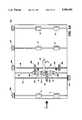
- FIG. 2is a schematic overhead plan view of the document turning device of FIG. 1;
- FIG. 3is a block diagram illustrating an intelligent algorithm used to produce a variable velocity profile to control the single variable speed drive to turn a document 90° as well as correct for input skew and output skew if any;
- FIG. 4is a schematic overhead plan view of a modified version of the embodiment illustrated in FIG. 1 which includes a ball-on-belt document conveying mechanism for conveying narrow sheets through the document turning device;
- FIGS. 5A and 5Bare schematic overhead plan views of a further modification of the embodiment illustrated in FIG. 1 wherein a shifting mechanism is included for selectively engaging each of the respective drive rollers with one of the constant speed drive and the variable speed drive for turning a document in either the clockwise or counterclockwise directions;
- FIG. 6is a schematic overhead plan view of a further modification of the embodiment illustrated in FIG. 1 which includes a mechanism for side registering sheets as well as for automatically shifting the drive rollers between the constant speed drive and the variable speed drive as well as including an additional sensor for side registering sheets which are not turned by the device; and
- FIG. 7is a schematic overhead plan view of a second embodiment of the present invention.
- FIG. 1shows a document turning device 2 according to a first embodiment of the present invention.
- a sheet 4 which enters document turning device 2 long edge first along a process direction Fis illustrated at a plurality of incremental positions as the document 4 is rotated 90° and passed through document turning device 2.
- a pair of detectors 12a, 12bdetect the leading edge of the sheet and indicate the presence of the sheet to a controller.
- the speed of drive roller 10is varied (decreased in the illustrated preferred embodiment) while drive roller 8 continues to rotate at constant velocity so that sheet 4 is rotated.
- the speed of drive roller 10is returned to the constant speed of drive roller 8 so that sheet 4 stops turning, preferably after being rotated 90°.
- each of the rollers illustrated in the figuresincludes a corresponding follower roller which is pressed into contact therewith to provide a nip for gripping and conveying the document 4 therebetween.
- Rollers 14are mounted on a common shaft which is movable in a direction out of the page, away from their corresponding follower rollers. As a document 4 is being rotated, output rollers 14 are separated from their corresponding follower rollers so that document 4 can be inserted therebetween as it is being rotated. After rotation is complete, output rollers 14 are moved back into contact with their corresponding follower rollers to grip and convey document 4 out of turning device 2 and onto downstream rollers 16.
- FIG. 2illustrates the various components and structure for controlling the operation of turning device 2.
- Each of the pairs of continuous constant speed rollers 6, 14 and 16are provided on a corresponding shaft which is driven at a continuous, substantially constant velocity by one of operating means 20a, 20c, and 20d, respectively.
- drive roller 8is attached to operating means 20b through a shaft and is driven at the same continuous constant speed.
- Each of the operating means 20a-dcould be a constant speed motor, however, preferably each of the operating means is merely a passive pulley, each of the operating means 20a-d being attached to a common drive belt (not shown) which is driven by a single constant speed motor.
- This single constant speed motorcan be synchronized with, or the same as, the motor which operates the paper feeding components of the printer or copier located upstream thereof.
- Drive roller 10is attached to a second operating means 18 through a shaft.
- Second operating means 18is capable of selectively operating drive roller 10 at a peripheral velocity which varies so that a document can be turned.
- Second operating means 18is preferably a stepper motor or servo system. The speed at which second operating means 18 rotates drive roller 10 is controlled by, for example, a CPU 19.
- CPU 19operates according to an intelligent algorithm to determine a variable velocity profile which is used by second operating means 18 to operate drive roller 10.
- the algorithmis referred to as being "intelligent" because it is able to modify the velocity profile used to operate second operating means 18 based upon external data such as the input skew of a document entering turning device 2 and the output skew of documents exiting turning device 2.
- the operation of the intelligent algorithmwill be described below.
- CPU 19also controls the movement of shaft 15 which contains output rollers 14 by controlling engaging means 13 for placing output rollers 14 in the engaging position (where they are engaged with their corresponding follower idler rollers) before and after a document is turned and for placing output drive rollers 14 in the disengaged position while the document is being turned.
- Engaging means 13is preferably a solenoid.
- CPU 19also receives information from an encoder 21 relating to the rotational velocity of first operating means 20b.
- first operating means 20bWhen documents are conveyed through turning device 2 without being rotated, drive roller 10 must be rotated at the same speed as drive roller 8.
- an encoder 21can provide CPU 19 with data relating to the instantaneous velocity of first operating means 20b so that second operating means 18 can operate roller 10 at the same speed as drive roller 8.
- Document turning device 2operates to rotate a document 90° as follows. Sensors 12a and 12b are used to sense the lead edge and determine the input skew of each document. Second operating means 18, which can be, for example a stepper motor, is then decelerated and accelerated again using a specific algorithm that rotates the sheet 90°, plus or minus the input skew that was measured for that sheet. At this point, the sheet should theoretically have been rotated 90° and deskewed. However, if the velocity of the constantly driven turn roller 8 drifts, or the rollers begin to wear, it is possible that the actual sheet rotation will differ from the theoretically determined motion. Because of this possible difference, one more step is taken in the rotation process.
- Second operating means 18which can be, for example a stepper motor
- the two sensors 12a, 12bare used to determine the output skew of the sheet from its trail edge. If the sheet is not perfectly deskewed, this information is fed back to the controller (CPU 19) and the variable velocity profile is updated to compensate for the measured error. Since this process is carried out for every sheet, the system can continuously compensate for velocity drift, roller wear or other noises in the system.
- a flow chart for the complete control algorithm usedis shown in FIG. 3.
- step 1control of drive roller 10 is initiated when a sheet is fed from a processor located upstream of turning device 2.
- step S2the blockade of either sensor 12a or 12b is ascertained.
- step S3the blockade of either sensor 12a or 12b is ascertained.
- step S4take away solenoid 13 is actuated to move shaft 15 so that output rollers 14 are disengaged from their corresponding follower rollers.
- step S5the blockage of both sensors 12a and 12b is ascertained. Once both sensors 12a and 12b are blocked, the algorithm proceeds to step S6 where the velocity profile through which step motor 18 will be operated is determined.
- step S6the timer is stopped and its value is assigned to the variable ⁇ t in .
- the value of ⁇ t inis proportional to the input skew of a document.
- ⁇ t inwas assigned a positive value for a Clockwise skew and a negative value for a counterclockwise skew (i.e., if sensor 12a is blocked first, ⁇ t in is positive) in the algorithm used with the described embodiment although the opposite arrangement can also be used as long as the algorithm is adjusted appropriately.
- the following calculationsare then made in step S6:
- VCequals the velocity of the constantly driven roller 8. It is recalled that prior to turning a document, both drive rollers 8 and 10 are operated at the same constant velocity (VC) so that initially the document is conveyed along in the process direction (indicated by arrow F) without being turned.
- K penis thus a predetermined constant value which is based upon the constant velocity speed VC of the apparatus, the distance between sensors 12a, 12b and drive rollers 8, 10 and the desired side registration position of outputted documents.
- the velocity profile through which second operating means 18 is operatedis determined in steps S8-S12.
- V maxi.e., initially step motor is operating at the same speed as the constant velocity drive
- variable speed drive roller 10could be brought to a complete stop or accelerated to speeds greater than VC.
- deceleration of drive roller 10is preferable because it can turn smaller sheets and is less damaging to the documents.
- step S8the velocity VS of stepper motor 18 is decelerated from V max to V min .
- V min0.2 V max has been found to be preferable although other values for V min can also be used.
- stepper motor 18After stepper motor 18 reaches V min , its speed is held constant for a time period equal to [(K rot -K skw )/VC] seconds, wherein K rot defines a predetermined time period, based upon V max , V min , the time period required to decelerate and accelerate between V max and V min , and the distance between driver rollers 8 and 10, required to rotate a document a desired amount, for example 90°.
- K rotdefines a predetermined time period, based upon V max , V min , the time period required to decelerate and accelerate between V max and V min , and the distance between driver rollers 8 and 10, required to rotate a document a desired amount, for example 90°.
- K rotdefines a predetermined time period, based upon V max , V min , the time period required to decelerate and accelerate between V max and V min , and the distance between driver rollers 8 and 10, required to rotate a document a desired amount, for example 90°.
- step S11the solenoid 13 is deactivated so that output rollers 14 engage the document and convey it out of turning device 2. Since output rollers 14 should not engage the document until drive roller 10 has reached the same velocity as drive roller 8, the deactivation of solenoid 13 is delayed, in step S10, for a time period equal to (K tar /VC) seconds, wherein K tar is a predetermined parameter.
- steps S13-S17are provided.
- the same sensors which detect the input skewi.e., sensors 12a and 12b
- Steps S13-S15are similar to steps S2-S4 except that the time period required between the unblocking of each sensor is determined as ⁇ t out .
- step S17The time factor K rot required to rotate a document by, for example, 90° is then adjusted in step S17 to correct for output skew according to the formula: ##EQU1## wherein A nom is a nominal angle through which the sheet is rotated while the variable speed roller is held at V min which is predetermined and K c is a correction factor which compensates for system noise and prevents over-correction from occurring.
- the algorithmthen proceeds to step S18 where a determination is made as to whether or not more sheets are being inputted. If more sheets are being inputted, the algorithm returns to step S2 to begin the turning procedure and uses the updated value of K rot to do so. If no more sheets are being fed, or if it is not necessary or desired to turn these sheets (e.g., if 90° set distinction is desired) the algorithm proceeds to step S19 where the last value of K rot is stored in memory.
- FIG. 4is a schematic plan view of a modification of the first embodiment of the present invention.
- a ball-on-belt conveying structure 22can be provided to assist in conveying smaller sheets of paper towards and away from drive rollers 8 and 10. It should be noted that drive rollers 8 and 10 are also located closer to each other for handling smaller (narrower) sheets.
- Ball-on-belt conveyor 22can be of a type well known in the art and includes a rotating conveyor belt 24 positioned on one side of the paper path and a housing 26 including a plurality of free rolling balls 28 therein which, when contacted with conveyor belt 24, provide a nip through which a sheet of paper is pressed against conveyor belt 24 to be moved thereby. Housing 26 is movable away from belt 24 so that a document can be freely rotated by drive roller 10. Housing 26 can be moved by a solenoid such as solenoid 13 used with output rollers 14.
- FIGS. 5A and 5Billustrate an additional modification to the first embodiment of the present invention wherein a shifting mechanism is provided for shifting the connection of the constant velocity drive motor and variable speed motor (stepper motor) between drive rollers 8 and 10 to provide for clockwise or counterclockwise rotation of a document.
- a shifting mechanismis provided for shifting the connection of the constant velocity drive motor and variable speed motor (stepper motor) between drive rollers 8 and 10 to provide for clockwise or counterclockwise rotation of a document.
- Practical considerationsmake it desirable to decelerate the variable speed roller 10 to a slower speed than the constantly driven roller 8 to achieve rotation rather than speeding up roller 10. Because of this, and in order to avoid using two step motors, the best way to convert a clockwise rotation system that has a constant velocity roller on the inboard side and a step motor driven roller on the outboard side, to a counterclockwise rotation system, is to simply switch the function of the two turn rollers 8, 10.
- a common shaft 30is provided for each of drive rollers 8 and 10.
- Drive rollers 8 and 10are mounted on respective sleeves 32a, 32b which are freely slidably and rotatably mounted on shaft 30.
- Each sleeve 32a, 32bincludes a first gear 34a, 34b, respectively, for engaging a gear 40a, 40b, respectively, which is rotated at a constant velocity by first operating means 20b through shaft 38.
- a second gear 35a, 35bis provided on each of sleeves 32a, 32b, respectively and is selectively engageable with gear 44 which is rotated by the second operating means 18 (stepper motor) through shaft 42.
- Each of sleeves 32a and 32bis attached to a common linkage 36 which can be moved, for example, by hand, to move sleeves 32a and 32b and thus rollers 8 and 10 along the axis of shaft 30 to selectively engage each of rollers 8 and 10 with one of the constant velocity motor or variable speed motor.
- FIG. 5Aillustrates the position of linkage 36 where drive roller 8 is attached to the constant velocity motor while drive roller 10 is attached to the variable speed motor for rotating documents in the clockwise direction.
- FIG. 5Bshows the opposite arrangement for rotating documents in the counterclockwise direction. It is understood that linkage 36 can be operated manually or automatically by, for example, a solenoid or a motor.
- FIG. 6shows an arrangement where the switching of the attachments of drive rollers 8 and 10 to the first and second operating means 20b and 18, respectively, is controlled by a motor 50.
- sleeves 32a and 32bare not freely slidable along the axis of shaft 30 but are mounted to freely rotate thereabout.
- Shaft 30is movable along its axis by the operation of motor 50 which is attached to a worm gear 46 of shaft 30 through gear 48 which is attached to the shaft of motor 50.
- the embodiment illustrated in FIG. 6can also be used to side register unrotated sheets as they pass through drive rollers 8 and 10.
- drive rollers 8 and 10can be shifted in the direction indicated by arrow S to properly orient a side edge of the document.
- Sensor 12ccan be used to detect the side edge of the unrotated document.
- side registrationis not required when rotating documents because they are automatically side registered as they are rotated.
- turning device 2can also operate to deskew documents which are passed therethrough without being rotated by sensing the input skew with sensors 12a and 12b and then varying the speed of drive roller 10 to deskew the document. In this mode of operation, device 2 functions somewhat like existing deskewing devices, however, only a single variable speed drive (e.g., step motor 18) is required to deskew documents.
- FIG. 7illustrates a second embodiment of the present invention wherein skew sensors 12a and 12b are located upstream of drive rollers 8 and 10.
- This arrangementoperates in a manner similar to that described above.
- the input skewis determined by sensors 12a and 12b which can also detect the output skew of the document after rotation. Since the sheet will still be in the nip produced by drive rollers 8 and 10 and their corresponding follower rollers when the output skew is determined by sensors 12a and 12b, not only can the output skew be used to update the variable velocity profile used to rotate subsequent documents, but the output skew of the document which was just rotated can also be corrected by appropriately controlling drive roller 10.
- the present inventionprovides a number of advantages over previous sheet rotating systems. Since the sheets are always held in a positive nip, reliable operation and consistent rotation is ensured. The use of a positive nip also renders the present turning device more easily usable with documents having a variety of sizes. Since rotation and deskewing is accomplished without the use of edge guides, wear and buckling problems associated with edge registration technology is eliminated.
- the "intelligent" algorithm used with the present inventionmakes the system insensitive to roll wear and velocity drifts of the constant velocity motor. Only one step motor system and two sensors are required to accomplish both rotation and deskew, thus reducing construction and operation costs of the system.
- the system according to the present inventioncan be easily operated in a bypass mode without the use of additional gates or paper paths. Furthermore, by synchronizing the step motor to the constant velocity motor during the bypass operation, any drifting which does occur in the constant velocity motor does not result in skewing the documents passed therethrough.
- the present inventioncan be used with any device which handles documents and is particularly useful with printers and copiers.
- the turning device of the present inventioncan be used to achieve set distinction between a plurality of sets of documents by, for example, rotating alternate sets by 90°.
- the present inventioncan also be used between a copier or printer and a finishing apparatus so that documents exiting the copier or printer can be properly oriented prior to entering the finishing apparatus.
- Letter size documents which exit an upstream apparatus long edge firstcan be rotated 90° so that they enter, for example, a buckle folder, saddle stitcher, or direct mail system short edge first.
- Legal size (14) sheetscan be rotated, if necessary, so that they are fed short edge first to third party devices which compile and dual staple sheets along their top edge.
- A3/11 ⁇ 17" sheets produced by signature producing devicescan be rotated, if necessary, so that they are fed short edge first to enable saddle stitching and/or folding as disclosed in the above-incorporated U.S. Pat. No. 4,727,402. Any number of other applications for the present invention are also available as well as rotating sheets fed short edge first so that they exit the turning device long edge first.
Landscapes
- Engineering & Computer Science (AREA)
- Mechanical Engineering (AREA)
- Registering Or Overturning Sheets (AREA)
Abstract
Description
A.sub.input =tan.sup.-1 (Δt.sub.in ·VC/150)
K.sub.skw =A.sub.input ·125;
Claims (44)
Priority Applications (2)
| Application Number | Priority Date | Filing Date | Title |
|---|---|---|---|
| US07/560,872US5090683A (en) | 1990-07-31 | 1990-07-31 | Electronic sheet rotator with deskew, using single variable speed roller |
| JP3181041AJP2907592B2 (en) | 1990-07-31 | 1991-07-22 | Document rotation device |
Applications Claiming Priority (1)
| Application Number | Priority Date | Filing Date | Title |
|---|---|---|---|
| US07/560,872US5090683A (en) | 1990-07-31 | 1990-07-31 | Electronic sheet rotator with deskew, using single variable speed roller |
Publications (1)
| Publication Number | Publication Date |
|---|---|
| US5090683Atrue US5090683A (en) | 1992-02-25 |
Family
ID=24239715
Family Applications (1)
| Application Number | Title | Priority Date | Filing Date |
|---|---|---|---|
| US07/560,872Expired - LifetimeUS5090683A (en) | 1990-07-31 | 1990-07-31 | Electronic sheet rotator with deskew, using single variable speed roller |
Country Status (2)
| Country | Link |
|---|---|
| US (1) | US5090683A (en) |
| JP (1) | JP2907592B2 (en) |
Cited By (40)
| Publication number | Priority date | Publication date | Assignee | Title |
|---|---|---|---|---|
| US5156391A (en)* | 1991-11-04 | 1992-10-20 | Xerox Corporation | Short paper path electronic deskew system |
| US5377569A (en)* | 1993-05-07 | 1995-01-03 | Xerox Corporation | Signature booklet maker with a modified fold blade and a trim waste elimination device |
| US5575097A (en)* | 1995-03-16 | 1996-11-19 | Jeffrey P. Chou | Page turning device |
| US5695185A (en)* | 1995-10-06 | 1997-12-09 | Baldwin Technology Corporation | Apparatus and method for turning and orienting articles within an article pathway |
| US5724642A (en)* | 1996-09-27 | 1998-03-03 | Xerox Corporation | Duplex color printing system with curl control by sheet rotation between printing opposing sides |
| US5848344A (en)* | 1997-06-13 | 1998-12-08 | Xerox Corporation | Copy media registration module |
| EP0841276A3 (en)* | 1996-10-29 | 1999-02-03 | RIGOLI F.I.M.E. S.p.A. | Device for turning paper sheets into a desired orientation in a paper sheet folding machine |
| US5882006A (en)* | 1995-10-06 | 1999-03-16 | Baldwin Technology Corporation | Apparatus and method for turning and orienting articles within an article pathway |
| US5918876A (en)* | 1993-12-17 | 1999-07-06 | Canon Kabushiki Kaisha | Sheet conveying apparatus |
| US5931462A (en)* | 1996-06-17 | 1999-08-03 | C.P. Bourg S.A. | Method of sheet rotation and a sheet stacker with a sheet rotator |
| US6059285A (en)* | 1996-12-18 | 2000-05-09 | Canon Kabushiki Kaisha | Sheet conveying apparatus |
| USRE37007E1 (en)* | 1989-12-07 | 2001-01-02 | Mars Incorporated | Device for aligning sheets with plural drive roller groups on a common shaft |
| US6173952B1 (en)* | 1999-05-17 | 2001-01-16 | Xerox Corporation | Printer sheet deskewing system with automatic variable nip lateral spacing for different sheet sizes |
| US6338483B1 (en) | 1999-11-23 | 2002-01-15 | Jeffrey L. Andela | Single sheet feeder with selectively engageable prefeeding rolls |
| US6505832B2 (en)* | 1998-12-23 | 2003-01-14 | Xerox Corporation | Variable acceleration take-away roll (TAR) for high capacity feeder |
| US6609708B2 (en) | 1998-12-23 | 2003-08-26 | Xerox Corporation | Vacuum corrugation shuttle feed device for high capacity feeder |
| US6712356B2 (en) | 2000-02-09 | 2004-03-30 | Mars Incorporated | Self aligning transport mechanism for media of variable media widths |
| US20050067771A1 (en)* | 2003-08-29 | 2005-03-31 | Xerox Corporation | Precision paper registration using a stepper motor without employing micro-stepping techniques |
| US20050175386A1 (en)* | 2004-02-09 | 2005-08-11 | Eastman Kodak Company | Sheet deskewing method and apparatus |
| US20050263958A1 (en)* | 2004-05-27 | 2005-12-01 | Xerox Corporation | Print media registration using active tracking of idler rotation |
| EP1607228A3 (en)* | 2004-06-16 | 2006-02-22 | Hewlett-Packard Indigo B.V. | Paper rotation method and apparatus |
| US20060087664A1 (en)* | 2004-10-27 | 2006-04-27 | Pozuelo Francisco J | Inter-device media handler |
| US20060156876A1 (en)* | 2005-01-19 | 2006-07-20 | Pitney Bowes Incorporated | Motion control system and method for a high speed inserter input |
| US20060214364A1 (en)* | 2005-03-25 | 2006-09-28 | Xerox Corporation | Sheet registration within a media inverter |
| US20060269337A1 (en)* | 2005-05-27 | 2006-11-30 | Canon Kabushiki Kaisha | Image forming apparatus with error correction for length of transfer sheet |
| US20060291018A1 (en)* | 2005-06-24 | 2006-12-28 | Xerox Corporation | Mixed output print control method and system |
| US20070120934A1 (en)* | 2005-11-30 | 2007-05-31 | Xerox Corporation | Mixed output printing system |
| US20070120305A1 (en)* | 2005-11-30 | 2007-05-31 | Xerox Corporation | Radial merge module for printing system |
| US20080048386A1 (en)* | 2006-08-22 | 2008-02-28 | Xerox Corporation | Sheet rotator |
| US20080128984A1 (en)* | 2006-12-01 | 2008-06-05 | Pitney Bowes Incorporated | Method and apparatus for enhanced cutter throughput using an exit motion profile |
| US20090107892A1 (en)* | 2007-10-31 | 2009-04-30 | Pitney Bowes Inc. | Sheet material transposition for sorting apparatus |
| US20090134570A1 (en)* | 2007-11-28 | 2009-05-28 | Canon Kabushiki Kaisha | Sheet conveying apparatus and image forming apparatus |
| US20100288145A1 (en)* | 2009-04-29 | 2010-11-18 | Goss International Americas, Inc. | High speed printed product reorientation method and apparatus |
| US20110243618A1 (en)* | 2010-04-05 | 2011-10-06 | Konica Minolta Business Technologies, Inc. | Image forming apparatus |
| US20110291352A1 (en)* | 2009-05-29 | 2011-12-01 | Xerox Corporation | Accurate Sheet Leading Edge Registration |
| CH706657A1 (en)* | 2012-06-29 | 2013-12-31 | Kern Ag | Device for turning flat sheet- or film-like products or a batch. |
| US20160176671A1 (en)* | 2014-12-18 | 2016-06-23 | Lexmark International, Inc. | Multiple Edge Media Stapling System |
| US9802777B2 (en)* | 2014-11-28 | 2017-10-31 | Océ-Technologies B.V. | Belt conveyor system comprising a mesh belt and a sheet conveyor system for conveying sheets in a reprographic apparatus |
| US10329109B1 (en) | 2018-04-03 | 2019-06-25 | Xerox Corporation | Vacuum shuttle with stitch and roll capabilities |
| US10584009B1 (en)* | 2019-08-02 | 2020-03-10 | Capital One Services, Llc | Sheet orienting apparatus using ball drive |
Families Citing this family (2)
| Publication number | Priority date | Publication date | Assignee | Title |
|---|---|---|---|---|
| JP4587615B2 (en)* | 2001-08-10 | 2010-11-24 | ホリゾン・インターナショナル株式会社 | Paper orientation conversion device |
| JP2021149756A (en)* | 2020-03-23 | 2021-09-27 | グローリー株式会社 | Paper sheet transport device and paper sheet processing device |
Citations (17)
| Publication number | Priority date | Publication date | Assignee | Title |
|---|---|---|---|---|
| US3240487A (en)* | 1963-04-03 | 1966-03-15 | Burroughs Corp | Sheet aligning feed mechanism |
| US3589808A (en)* | 1969-06-02 | 1971-06-29 | Xerox Corp | Reproducing apparatus |
| US3603446A (en)* | 1969-03-27 | 1971-09-07 | Black Clawson Co | Sheet-straightening mechanism |
| US3758104A (en)* | 1971-09-23 | 1973-09-11 | W Daily | Turning apparatus |
| US4076408A (en)* | 1976-03-30 | 1978-02-28 | Eastman Kodak Company | Collating document feeder with multiple feed detector |
| US4082456A (en)* | 1975-12-27 | 1978-04-04 | Hoechst Aktiengesellschaft | Device for adjusting an original to be copied |
| US4155440A (en)* | 1977-07-05 | 1979-05-22 | Pitney-Bowes, Inc. | Document turning station |
| US4438917A (en)* | 1981-10-16 | 1984-03-27 | International Business Machines Corporation | Dual motor aligner |
| US4500086A (en)* | 1982-12-01 | 1985-02-19 | Xerox Corporation | Rotating inverter |
| US4511242A (en)* | 1982-12-22 | 1985-04-16 | International Business Machines Corporation | Electronic alignment for a paper processing machine |
| US4669719A (en)* | 1986-06-02 | 1987-06-02 | Xerox Corporation | Sheet rotation and registration vertical transport |
| US4727402A (en)* | 1986-12-18 | 1988-02-23 | Xerox Corporation | Automatic copier signature set production |
| US4855607A (en)* | 1987-12-30 | 1989-08-08 | Pitney Bowes, Inc. | Apparatus for aligning a moving substrate and a read or write head |
| US4877234A (en)* | 1988-08-02 | 1989-10-31 | Xerox Corporation | Sheet turning and registration system |
| US4955964A (en)* | 1988-08-19 | 1990-09-11 | Ncr Corporation | Sheet handling apparatus |
| US4955965A (en)* | 1988-12-05 | 1990-09-11 | Xerox Corporation | Positive drive, passive, sheet rotation device using differential roll velocities |
| US4971304A (en)* | 1986-12-10 | 1990-11-20 | Xerox Corporation | Apparatus and method for combined deskewing and side registering |
- 1990
- 1990-07-31USUS07/560,872patent/US5090683A/ennot_activeExpired - Lifetime
- 1991
- 1991-07-22JPJP3181041Apatent/JP2907592B2/ennot_activeExpired - Fee Related
Patent Citations (17)
| Publication number | Priority date | Publication date | Assignee | Title |
|---|---|---|---|---|
| US3240487A (en)* | 1963-04-03 | 1966-03-15 | Burroughs Corp | Sheet aligning feed mechanism |
| US3603446A (en)* | 1969-03-27 | 1971-09-07 | Black Clawson Co | Sheet-straightening mechanism |
| US3589808A (en)* | 1969-06-02 | 1971-06-29 | Xerox Corp | Reproducing apparatus |
| US3758104A (en)* | 1971-09-23 | 1973-09-11 | W Daily | Turning apparatus |
| US4082456A (en)* | 1975-12-27 | 1978-04-04 | Hoechst Aktiengesellschaft | Device for adjusting an original to be copied |
| US4076408A (en)* | 1976-03-30 | 1978-02-28 | Eastman Kodak Company | Collating document feeder with multiple feed detector |
| US4155440A (en)* | 1977-07-05 | 1979-05-22 | Pitney-Bowes, Inc. | Document turning station |
| US4438917A (en)* | 1981-10-16 | 1984-03-27 | International Business Machines Corporation | Dual motor aligner |
| US4500086A (en)* | 1982-12-01 | 1985-02-19 | Xerox Corporation | Rotating inverter |
| US4511242A (en)* | 1982-12-22 | 1985-04-16 | International Business Machines Corporation | Electronic alignment for a paper processing machine |
| US4669719A (en)* | 1986-06-02 | 1987-06-02 | Xerox Corporation | Sheet rotation and registration vertical transport |
| US4971304A (en)* | 1986-12-10 | 1990-11-20 | Xerox Corporation | Apparatus and method for combined deskewing and side registering |
| US4727402A (en)* | 1986-12-18 | 1988-02-23 | Xerox Corporation | Automatic copier signature set production |
| US4855607A (en)* | 1987-12-30 | 1989-08-08 | Pitney Bowes, Inc. | Apparatus for aligning a moving substrate and a read or write head |
| US4877234A (en)* | 1988-08-02 | 1989-10-31 | Xerox Corporation | Sheet turning and registration system |
| US4955964A (en)* | 1988-08-19 | 1990-09-11 | Ncr Corporation | Sheet handling apparatus |
| US4955965A (en)* | 1988-12-05 | 1990-09-11 | Xerox Corporation | Positive drive, passive, sheet rotation device using differential roll velocities |
Non-Patent Citations (4)
| Title |
|---|
| IBM Technical Disclosure Bulletin, vol. 14, No. 7, Dec. 1971 (p. 2179).* |
| Research Closure, Nov. 1979.* |
| Xerox Disclosure Journal, vol. 12, No. 4, Jul./Aug. 1987 (pp. 205 206).* |
| Xerox Disclosure Journal, vol. 12, No. 4, Jul./Aug. 1987 (pp. 205-206). |
Cited By (65)
| Publication number | Priority date | Publication date | Assignee | Title |
|---|---|---|---|---|
| USRE37007E1 (en)* | 1989-12-07 | 2001-01-02 | Mars Incorporated | Device for aligning sheets with plural drive roller groups on a common shaft |
| US5156391A (en)* | 1991-11-04 | 1992-10-20 | Xerox Corporation | Short paper path electronic deskew system |
| US5377569A (en)* | 1993-05-07 | 1995-01-03 | Xerox Corporation | Signature booklet maker with a modified fold blade and a trim waste elimination device |
| US5445592A (en)* | 1993-05-07 | 1995-08-29 | Xerox Corporation | Signature booklet maker with a modified fold blade and a trim waste elimination device |
| EP0658503B1 (en)* | 1993-12-17 | 2001-04-04 | Canon Kabushiki Kaisha | Sheet conveying apparatus |
| US5918876A (en)* | 1993-12-17 | 1999-07-06 | Canon Kabushiki Kaisha | Sheet conveying apparatus |
| US5575097A (en)* | 1995-03-16 | 1996-11-19 | Jeffrey P. Chou | Page turning device |
| US5695185A (en)* | 1995-10-06 | 1997-12-09 | Baldwin Technology Corporation | Apparatus and method for turning and orienting articles within an article pathway |
| US5882006A (en)* | 1995-10-06 | 1999-03-16 | Baldwin Technology Corporation | Apparatus and method for turning and orienting articles within an article pathway |
| US5931462A (en)* | 1996-06-17 | 1999-08-03 | C.P. Bourg S.A. | Method of sheet rotation and a sheet stacker with a sheet rotator |
| US5724642A (en)* | 1996-09-27 | 1998-03-03 | Xerox Corporation | Duplex color printing system with curl control by sheet rotation between printing opposing sides |
| EP0841276A3 (en)* | 1996-10-29 | 1999-02-03 | RIGOLI F.I.M.E. S.p.A. | Device for turning paper sheets into a desired orientation in a paper sheet folding machine |
| US6059285A (en)* | 1996-12-18 | 2000-05-09 | Canon Kabushiki Kaisha | Sheet conveying apparatus |
| US5848344A (en)* | 1997-06-13 | 1998-12-08 | Xerox Corporation | Copy media registration module |
| US6505832B2 (en)* | 1998-12-23 | 2003-01-14 | Xerox Corporation | Variable acceleration take-away roll (TAR) for high capacity feeder |
| US6609708B2 (en) | 1998-12-23 | 2003-08-26 | Xerox Corporation | Vacuum corrugation shuttle feed device for high capacity feeder |
| US6173952B1 (en)* | 1999-05-17 | 2001-01-16 | Xerox Corporation | Printer sheet deskewing system with automatic variable nip lateral spacing for different sheet sizes |
| US6338483B1 (en) | 1999-11-23 | 2002-01-15 | Jeffrey L. Andela | Single sheet feeder with selectively engageable prefeeding rolls |
| US6712356B2 (en) | 2000-02-09 | 2004-03-30 | Mars Incorporated | Self aligning transport mechanism for media of variable media widths |
| US6910689B2 (en)* | 2003-08-29 | 2005-06-28 | Xerox Corporation | Precision paper registration using a stepper motor without employing micro-stepping techniques |
| US20050067771A1 (en)* | 2003-08-29 | 2005-03-31 | Xerox Corporation | Precision paper registration using a stepper motor without employing micro-stepping techniques |
| US20050175386A1 (en)* | 2004-02-09 | 2005-08-11 | Eastman Kodak Company | Sheet deskewing method and apparatus |
| US6997455B2 (en)* | 2004-02-09 | 2006-02-14 | Eastman Kodak Company | Sheet deskewing method and apparatus |
| US20050263958A1 (en)* | 2004-05-27 | 2005-12-01 | Xerox Corporation | Print media registration using active tracking of idler rotation |
| US7243917B2 (en)* | 2004-05-27 | 2007-07-17 | Xerox Corporation | Print media registration using active tracking of idler rotation |
| EP1607228A3 (en)* | 2004-06-16 | 2006-02-22 | Hewlett-Packard Indigo B.V. | Paper rotation method and apparatus |
| US20060087664A1 (en)* | 2004-10-27 | 2006-04-27 | Pozuelo Francisco J | Inter-device media handler |
| US7643161B2 (en) | 2004-10-27 | 2010-01-05 | Hewlett-Packard Development Company, L.P. | Inter-device media handler |
| US20060156876A1 (en)* | 2005-01-19 | 2006-07-20 | Pitney Bowes Incorporated | Motion control system and method for a high speed inserter input |
| US7258340B2 (en)* | 2005-03-25 | 2007-08-21 | Xerox Corporation | Sheet registration within a media inverter |
| US20060214364A1 (en)* | 2005-03-25 | 2006-09-28 | Xerox Corporation | Sheet registration within a media inverter |
| US20060269337A1 (en)* | 2005-05-27 | 2006-11-30 | Canon Kabushiki Kaisha | Image forming apparatus with error correction for length of transfer sheet |
| US20100322653A1 (en)* | 2005-05-27 | 2010-12-23 | Canon Kabushiki Kaisha | Image forming apparatus with error correction for length of transfer sheet |
| US7792479B2 (en)* | 2005-05-27 | 2010-09-07 | Canon Kabushiki Kaisha | Image forming apparatus with error correction for length of transfer sheet |
| US8081329B2 (en)* | 2005-06-24 | 2011-12-20 | Xerox Corporation | Mixed output print control method and system |
| US20060291018A1 (en)* | 2005-06-24 | 2006-12-28 | Xerox Corporation | Mixed output print control method and system |
| US7636543B2 (en) | 2005-11-30 | 2009-12-22 | Xerox Corporation | Radial merge module for printing system |
| US20070120305A1 (en)* | 2005-11-30 | 2007-05-31 | Xerox Corporation | Radial merge module for printing system |
| US20070120934A1 (en)* | 2005-11-30 | 2007-05-31 | Xerox Corporation | Mixed output printing system |
| US7706737B2 (en) | 2005-11-30 | 2010-04-27 | Xerox Corporation | Mixed output printing system |
| US7669842B2 (en) | 2006-08-22 | 2010-03-02 | Xerox Corporation | Sheet rotator |
| US20080048386A1 (en)* | 2006-08-22 | 2008-02-28 | Xerox Corporation | Sheet rotator |
| US7752948B2 (en)* | 2006-12-01 | 2010-07-13 | Pitney Bowes Inc. | Method and apparatus for enhanced cutter throughput using an exit motion profile |
| US20080128984A1 (en)* | 2006-12-01 | 2008-06-05 | Pitney Bowes Incorporated | Method and apparatus for enhanced cutter throughput using an exit motion profile |
| US20100236365A1 (en)* | 2006-12-01 | 2010-09-23 | Pitney Bowes Inc. | Method and apparatus for enhanced cutter throughput using an exit motion profile |
| US9309082B2 (en) | 2006-12-01 | 2016-04-12 | Pitney Bowes Inc. | Method and apparatus for enhanced cutter throughput using an exit motion profile |
| US20090107892A1 (en)* | 2007-10-31 | 2009-04-30 | Pitney Bowes Inc. | Sheet material transposition for sorting apparatus |
| US8002275B2 (en)* | 2007-11-28 | 2011-08-23 | Canon Kabushiki Kaisha | Sheet conveying apparatus and image forming apparatus having a first skew feeding correction unit and a second skew feeding correction unit |
| US20090134570A1 (en)* | 2007-11-28 | 2009-05-28 | Canon Kabushiki Kaisha | Sheet conveying apparatus and image forming apparatus |
| EP2424734A4 (en)* | 2009-04-29 | 2012-09-26 | Goss Int Americas Inc | DEVICE AND METHOD FOR REALIGNING A PRODUCT PRINTED AT HIGH SPEED |
| US20100288145A1 (en)* | 2009-04-29 | 2010-11-18 | Goss International Americas, Inc. | High speed printed product reorientation method and apparatus |
| US8366102B2 (en)* | 2009-05-29 | 2013-02-05 | Xerox Corporation | Accurate sheet leading edge registration |
| US20110291352A1 (en)* | 2009-05-29 | 2011-12-01 | Xerox Corporation | Accurate Sheet Leading Edge Registration |
| US20110243618A1 (en)* | 2010-04-05 | 2011-10-06 | Konica Minolta Business Technologies, Inc. | Image forming apparatus |
| US8737890B2 (en)* | 2010-04-05 | 2014-05-27 | Konica Minolta Business Technologies, Inc. | Image forming apparatus with steering roller and position control mechanism |
| CH706657A1 (en)* | 2012-06-29 | 2013-12-31 | Kern Ag | Device for turning flat sheet- or film-like products or a batch. |
| US20150246786A1 (en)* | 2012-06-29 | 2015-09-03 | Kern Ag | Rotating device for flat products or for a stack thereof |
| US9555991B2 (en)* | 2012-06-29 | 2017-01-31 | Kern Ag | Rotating device for flat products or for a stack thereof |
| EP2867148B1 (en)* | 2012-06-29 | 2019-04-10 | Kern AG | Rotating device for flat products or for a stack thereof |
| US9802777B2 (en)* | 2014-11-28 | 2017-10-31 | Océ-Technologies B.V. | Belt conveyor system comprising a mesh belt and a sheet conveyor system for conveying sheets in a reprographic apparatus |
| US20160176671A1 (en)* | 2014-12-18 | 2016-06-23 | Lexmark International, Inc. | Multiple Edge Media Stapling System |
| US9751713B2 (en)* | 2014-12-18 | 2017-09-05 | Lexmark International, Inc. | Multiple edge media stapling system |
| US10329109B1 (en) | 2018-04-03 | 2019-06-25 | Xerox Corporation | Vacuum shuttle with stitch and roll capabilities |
| US10584009B1 (en)* | 2019-08-02 | 2020-03-10 | Capital One Services, Llc | Sheet orienting apparatus using ball drive |
| US10870551B1 (en)* | 2019-08-02 | 2020-12-22 | Capital One Services, Llc | Sheet orienting apparatus using ball drive |
Also Published As
| Publication number | Publication date |
|---|---|
| JPH04226240A (en) | 1992-08-14 |
| JP2907592B2 (en) | 1999-06-21 |
Similar Documents
| Publication | Publication Date | Title |
|---|---|---|
| US5090683A (en) | Electronic sheet rotator with deskew, using single variable speed roller | |
| US7631867B2 (en) | Moving carriage lateral registration system | |
| US6173952B1 (en) | Printer sheet deskewing system with automatic variable nip lateral spacing for different sheet sizes | |
| US4971304A (en) | Apparatus and method for combined deskewing and side registering | |
| US6168153B1 (en) | Printer sheet deskewing system with automatically variable numbers of upstream feeding NIP engagements for different sheet sizes | |
| US5449164A (en) | Sheet inverter apparatus | |
| EP1728743B1 (en) | Method and system for skew and lateral offset adjustment | |
| US6817609B2 (en) | Printer sheet lateral registration system with automatic upstream nip disengagements for different sheet size | |
| US6736394B2 (en) | Printer lateral and deskew sheet registration system | |
| JP2941851B2 (en) | Paper rotation mechanism | |
| US10239715B2 (en) | Sheet folding method, image forming system, and sheet folding device with motor employing being controlled to perform a feedback control with an integral gain | |
| US5476256A (en) | Disk stacker including passive sheet registration assist system | |
| JPS5813460B2 (en) | Sheet multiple offset group sorting and feeding device | |
| JP3592038B2 (en) | Sheet conveying device, and image reading device and image forming device provided with the same | |
| JP2603358B2 (en) | Printing device | |
| US6488275B2 (en) | Active pre-registration system using long sheet transports | |
| JP2009035417A (en) | Sheet stacking device and post-treatment device having the same | |
| JP2018167922A (en) | Paper sheet skew correction device | |
| US4146220A (en) | Document handling apparatus | |
| JPH061498A (en) | Sheet adjusting device | |
| JPH1159965A (en) | Paper transport device | |
| US6474634B2 (en) | Active pre-registration system employing a paper supply elevator | |
| JP2002370850A (en) | Paper conveyance device and image forming device | |
| JP2003146484A (en) | Sheet carrier | |
| JP2003165672A (en) | Sheet material folding machine |
Legal Events
| Date | Code | Title | Description |
|---|---|---|---|
| AS | Assignment | Owner name:XEROX CORPORATION, CONNECTICUT Free format text:ASSIGNMENT OF ASSIGNORS INTEREST.;ASSIGNORS:MANDEL, BARRY P.;SOKAC, RUSSELL J.;BEER, TED A.;AND OTHERS;REEL/FRAME:005458/0457;SIGNING DATES FROM 19900813 TO 19900814 | |
| STCF | Information on status: patent grant | Free format text:PATENTED CASE | |
| FEPP | Fee payment procedure | Free format text:PAYOR NUMBER ASSIGNED (ORIGINAL EVENT CODE: ASPN); ENTITY STATUS OF PATENT OWNER: LARGE ENTITY | |
| FPAY | Fee payment | Year of fee payment:4 | |
| FPAY | Fee payment | Year of fee payment:8 | |
| AS | Assignment | Owner name:BANK ONE, NA, AS ADMINISTRATIVE AGENT, ILLINOIS Free format text:SECURITY INTEREST;ASSIGNOR:XEROX CORPORATION;REEL/FRAME:013153/0001 Effective date:20020621 | |
| FPAY | Fee payment | Year of fee payment:12 | |
| AS | Assignment | Owner name:JPMORGAN CHASE BANK, AS COLLATERAL AGENT, TEXAS Free format text:SECURITY AGREEMENT;ASSIGNOR:XEROX CORPORATION;REEL/FRAME:015134/0476 Effective date:20030625 Owner name:JPMORGAN CHASE BANK, AS COLLATERAL AGENT,TEXAS Free format text:SECURITY AGREEMENT;ASSIGNOR:XEROX CORPORATION;REEL/FRAME:015134/0476 Effective date:20030625 | |
| AS | Assignment | Owner name:XEROX CORPORATION, CONNECTICUT Free format text:RELEASE BY SECURED PARTY;ASSIGNOR:JPMORGAN CHASE BANK, N.A. AS SUCCESSOR-IN-INTEREST ADMINISTRATIVE AGENT AND COLLATERAL AGENT TO JPMORGAN CHASE BANK;REEL/FRAME:066728/0193 Effective date:20220822 |