US5090448A - Connection for pipes of the type incorporating rotating valves - Google Patents
Connection for pipes of the type incorporating rotating valvesDownload PDFInfo
- Publication number
- US5090448A US5090448AUS07/650,428US65042891AUS5090448AUS 5090448 AUS5090448 AUS 5090448AUS 65042891 AUS65042891 AUS 65042891AUS 5090448 AUS5090448 AUS 5090448A
- Authority
- US
- United States
- Prior art keywords
- valve members
- valve
- elements
- connector
- pusher
- Prior art date
- Legal status (The legal status is an assumption and is not a legal conclusion. Google has not performed a legal analysis and makes no representation as to the accuracy of the status listed.)
- Expired - Lifetime
Links
- 238000007789sealingMethods0.000claimsdescription4
- 230000000717retained effectEffects0.000claimsdescription2
- 238000010276constructionMethods0.000description4
- 230000000694effectsEffects0.000description3
- 239000012530fluidSubstances0.000description2
- 239000007788liquidSubstances0.000description2
- 238000004140cleaningMethods0.000description1
Images


Classifications
- F—MECHANICAL ENGINEERING; LIGHTING; HEATING; WEAPONS; BLASTING
- F16—ENGINEERING ELEMENTS AND UNITS; GENERAL MEASURES FOR PRODUCING AND MAINTAINING EFFECTIVE FUNCTIONING OF MACHINES OR INSTALLATIONS; THERMAL INSULATION IN GENERAL
- F16L—PIPES; JOINTS OR FITTINGS FOR PIPES; SUPPORTS FOR PIPES, CABLES OR PROTECTIVE TUBING; MEANS FOR THERMAL INSULATION IN GENERAL
- F16L37/00—Couplings of the quick-acting type
- F16L37/22—Couplings of the quick-acting type in which the connection is maintained by means of balls, rollers or helical springs under radial pressure between the parts
- F16L37/23—Couplings of the quick-acting type in which the connection is maintained by means of balls, rollers or helical springs under radial pressure between the parts by means of balls
- F—MECHANICAL ENGINEERING; LIGHTING; HEATING; WEAPONS; BLASTING
- F16—ENGINEERING ELEMENTS AND UNITS; GENERAL MEASURES FOR PRODUCING AND MAINTAINING EFFECTIVE FUNCTIONING OF MACHINES OR INSTALLATIONS; THERMAL INSULATION IN GENERAL
- F16L—PIPES; JOINTS OR FITTINGS FOR PIPES; SUPPORTS FOR PIPES, CABLES OR PROTECTIVE TUBING; MEANS FOR THERMAL INSULATION IN GENERAL
- F16L37/00—Couplings of the quick-acting type
- F16L37/28—Couplings of the quick-acting type with fluid cut-off means
- F16L37/30—Couplings of the quick-acting type with fluid cut-off means with fluid cut-off means in each of two pipe-end fittings
- F16L37/373—Couplings of the quick-acting type with fluid cut-off means with fluid cut-off means in each of two pipe-end fittings with two taps or cocks
- Y—GENERAL TAGGING OF NEW TECHNOLOGICAL DEVELOPMENTS; GENERAL TAGGING OF CROSS-SECTIONAL TECHNOLOGIES SPANNING OVER SEVERAL SECTIONS OF THE IPC; TECHNICAL SUBJECTS COVERED BY FORMER USPC CROSS-REFERENCE ART COLLECTIONS [XRACs] AND DIGESTS
- Y10—TECHNICAL SUBJECTS COVERED BY FORMER USPC
- Y10T—TECHNICAL SUBJECTS COVERED BY FORMER US CLASSIFICATION
- Y10T137/00—Fluid handling
- Y10T137/8593—Systems
- Y10T137/87917—Flow path with serial valves and/or closures
- Y10T137/87925—Separable flow path section, valve or closure in each
- Y10T137/87941—Each valve and/or closure operated by coupling motion
- Y10T137/87949—Linear motion of flow path sections operates both
Definitions
- the present inventionrelates to connection devices for the removable union of pipes and more particularly to connections of the type incorporating rotating valves.
- Devices of this typeare known to comprise two elements which are fixed to the ends of the pipes to be connected, being provided with means for allowing assembly and disassembly thereof.
- a valve of substantially spherical profilewhich valve includes a through bore oriented parallel to the axis of the connection.
- This valveis mounted to pivot in the body of the element in question with the aid of a transverse pivot which is offset with respect to the center of the valve, so that, by thrust during assembly of the two elements of the connection, the valve pivots against elastic means in order to pass from a closed position in which its bore is oriented in substantially transverse manner, to an open position in which the axes of the bore and of the connection merge.
- the pivot of the valveis generally constituted by two pins which are carried by the head of a tubular shank oriented axially so that the head is engaged inside the bore of the valve and the pins cooperate with recesses made in the wall of the bore.
- meansare provided on the head of the axial tubular shank, for ensuring correct guiding of the valve during the pivoting thereof.
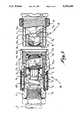
- FIG. 1is a schematic axial section of a connection incorporating rotating valves according to the present invention.
- FIG. 2reproduces FIG. 1 after assembly of the two elements constituting the device for connecting the pipes in question.
- FIG. 3is a transverse section along the plane III--III in FIG. 2.
- FIG. 4shows in perspective, prior to being mounted in the body and to assembly thereof, the principal parts constituting one or the other of the two elements of the connection.
- connection shown in FIGS. 1 and 2is constituted in conventional manner by two elements A and B adapted to be fixed to the ends of the pipes to be connected and to be selectively assembled to each other.
- Each of these elementscomprises a tubular body 1 of which the rear part is adapted to receive, by screwing in the present case, a joining piece 2 secured to a flexible pipe 3.
- any known systemmay be used for assembling the two elements A and B.
- the body 1 of the element Awas provided to be threaded into a rotating ring 4 retained axially on the element B by balls 5 maintained between an outer sleeve 6 and secured to ring 4 and an inner sheath 7 screwed on the body 1 of element B; any risk of untimely unscrewing of the ring 4 is prevented by a counter-nut 8 carried by element A.
- FIG. 4shows particularly well the mode of mounting each valve 9 in the corresponding body 1.
- the body 1includes an axial extension which includes a bifurcated semi-cylindrical arms, between the two longitudinal arms 1a of which are engaged a spring 10 and a piston 11; the end of the piston which faces the valve 9 widens at 11a to receive an O-ring 12 (FIG. 1) which the spring 10 maintains firmly applied against the valve 9.
- the valveincludes two plane outer faces 9b (FIG. 4) oriented parallel to each other and of which each includes a recess 9c of elongated profile along a diagonal of the face in question; in each recess 9c is engaged the end of a transverse pin 13 which is secured with one of the arms 1a by introduction into a bore 1b.
- the bores 1bare offset laterally with respect to the median axis of each of the arms 1a.
- the recesses 9care offset on the plane faces 9b with respect to the center thereof, with the result that the two pins 13 define for each valve 9 an out-of-center pivot such that, when the valve receives a thrust effort oriented longitudinally from front to rear, it pivots by rotation to pass from the position of closure according to FIG. 1 to the open position according to FIG. 2.
- the thrust effortis exerted by a tubular pusher 14 which slides axially on the axial bifurcated extension of the body 1 of each element A or B.
- Each pusher 14comprises an inner O-ring 15 against which is tightly applied valve 9 under the effect of spring 10.
- one of the two pushers 14namely the one mounted inside element B in the present case
- the uncoupled position shown in FIG. 1will be the starting point for describing the operation of the device described hereinabove.
- the male element Ais engaged in the front opening of ring 4; during mutual screwing of the two elements, the bottoms of the two pushers 14 come into contact with each other, with the result that the pushers are repelled axially.
- Each of the two valves 9is itself pushed inwardly by its pusher 4, so that, due to the offset of the pivot formed by the two pins 13, it is obliged to pivot.
- the assembled position illustrated in FIG. 2is finally obtained, the two valves 9 thus being brought into open position for which the two bores 9a are oriented along the axis of the device.
- connectionis very simple, the mounting operations being able to be carried out without particular difficulty. Moreover, it will be observed that, in the coupled position according to FIG. 2, the fluid which passes through the connection comes into contact only with the inner wall of the bores 9a of the valves 9, with the result that the device may be cleaned simply by passage of a stream of liquid, without any dismantling.
- each valve 9may present a circular profile of diameter greater than that of the pins 13, instead of the diagonally elongated profile illustrated in FIG. 4.
Landscapes
- General Engineering & Computer Science (AREA)
- Engineering & Computer Science (AREA)
- Mechanical Engineering (AREA)
- Quick-Acting Or Multi-Walled Pipe Joints (AREA)
- Joints That Cut Off Fluids, And Hose Joints (AREA)
- Coupling Device And Connection With Printed Circuit (AREA)
- Supports For Pipes And Cables (AREA)
- Valve-Gear Or Valve Arrangements (AREA)
- Pivots And Pivotal Connections (AREA)
- Duct Arrangements (AREA)
- Valve Housings (AREA)
- Feeding And Controlling Fuel (AREA)
- Infusion, Injection, And Reservoir Apparatuses (AREA)
Abstract
Description
1. Field of the Invention
The present invention relates to connection devices for the removable union of pipes and more particularly to connections of the type incorporating rotating valves.
2. History of the Related Art
Devices of this type are known to comprise two elements which are fixed to the ends of the pipes to be connected, being provided with means for allowing assembly and disassembly thereof. Inside each element is mounted a valve of substantially spherical profile, which valve includes a through bore oriented parallel to the axis of the connection. This valve is mounted to pivot in the body of the element in question with the aid of a transverse pivot which is offset with respect to the center of the valve, so that, by thrust during assembly of the two elements of the connection, the valve pivots against elastic means in order to pass from a closed position in which its bore is oriented in substantially transverse manner, to an open position in which the axes of the bore and of the connection merge.
In conventional constructions, the pivot of the valve is generally constituted by two pins which are carried by the head of a tubular shank oriented axially so that the head is engaged inside the bore of the valve and the pins cooperate with recesses made in the wall of the bore. In addition, means are provided on the head of the axial tubular shank, for ensuring correct guiding of the valve during the pivoting thereof.
It will be readily understood that such an arrangement necessarily involves a relatively complicated construction and fairly difficult assembly operations, which results in a substantial increase in the cost of the connection. Furthermore, the presence of the axial shank and of the pivot pins inside the bore of the valve obviously hinders the cleaning operations which necessitate complete dismantling of the parts constituting the connection.
It is a principal object of the present invention to overcome these drawbacks by ensuring the valves pivot to an open position at the same time as they are guided inside the body of each element of the connection, with the aid of a pivot formed by two lateral pins which cooperate with enlarged openings made on the one hand in the outer wall of the valve, on the other hand in bores in inner face of the arms which extends outwardly of the body.
It will be readily appreciated that a much simplified construction is thereby obtained, which in addition allows the space inside the connection to be cleaned by passage of a stream of liquid without any dismantling since the fluid which passes through the connection in normal use only comes in contact with the inner wall of the bore of each valve.
The invention will be more readily understood on reading the following description with reference to the accompanying drawings, in which:
FIG. 1 is a schematic axial section of a connection incorporating rotating valves according to the present invention.
FIG. 2 reproduces FIG. 1 after assembly of the two elements constituting the device for connecting the pipes in question.
FIG. 3 is a transverse section along the plane III--III in FIG. 2.
FIG. 4 shows in perspective, prior to being mounted in the body and to assembly thereof, the principal parts constituting one or the other of the two elements of the connection.
Referring now to the drawings, the connection shown in FIGS. 1 and 2 is constituted in conventional manner by two elements A and B adapted to be fixed to the ends of the pipes to be connected and to be selectively assembled to each other. Each of these elements comprises atubular body 1 of which the rear part is adapted to receive, by screwing in the present case, a joiningpiece 2 secured to aflexible pipe 3.
Any known system may be used for assembling the two elements A and B. In the embodiment shown, it has been assumed that thebody 1 of the element A was provided to be threaded into a rotatingring 4 retained axially on the element B byballs 5 maintained between anouter sleeve 6 and secured toring 4 and aninner sheath 7 screwed on thebody 1 of element B; any risk of untimely unscrewing of thering 4 is prevented by acounter-nut 8 carried by element A.
Inside thebody 1 of each element A and B is mounted a rotatingvalve 9 of substantially spherical profile, the valve being provided with abore 9a. FIG. 4 shows particularly well the mode of mounting eachvalve 9 in thecorresponding body 1.
As shown, thebody 1 includes an axial extension which includes a bifurcated semi-cylindrical arms, between the twolongitudinal arms 1a of which are engaged aspring 10 and apiston 11; the end of the piston which faces thevalve 9 widens at 11a to receive an O-ring 12 (FIG. 1) which thespring 10 maintains firmly applied against thevalve 9. The valve includes two planeouter faces 9b (FIG. 4) oriented parallel to each other and of which each includes arecess 9c of elongated profile along a diagonal of the face in question; in eachrecess 9c is engaged the end of atransverse pin 13 which is secured with one of thearms 1a by introduction into abore 1b.
It should be observed that thebores 1b are offset laterally with respect to the median axis of each of thearms 1a. In the same way, therecesses 9c are offset on the plane faces 9b with respect to the center thereof, with the result that the twopins 13 define for eachvalve 9 an out-of-center pivot such that, when the valve receives a thrust effort oriented longitudinally from front to rear, it pivots by rotation to pass from the position of closure according to FIG. 1 to the open position according to FIG. 2.
The thrust effort is exerted by atubular pusher 14 which slides axially on the axial bifurcated extension of thebody 1 of each element A or B. Eachpusher 14 comprises an inner O-ring 15 against which is tightly appliedvalve 9 under the effect ofspring 10. Furthermore, it will be noted that one of the two pushers 14 (namely the one mounted inside element B in the present case) is provided with an O-ring 16 fixed against the transverse outer wall or bottom of the pusher, so as to bear against the smooth bottom of thepusher 14 of element A during assembly of the two elements A and B, consequently ensuring a sealing of the connection.
The uncoupled position shown in FIG. 1 will be the starting point for describing the operation of the device described hereinabove. For assembling the two elements A and B, the male element A is engaged in the front opening ofring 4; during mutual screwing of the two elements, the bottoms of the twopushers 14 come into contact with each other, with the result that the pushers are repelled axially. Each of the twovalves 9 is itself pushed inwardly by itspusher 4, so that, due to the offset of the pivot formed by the twopins 13, it is obliged to pivot. The assembled position illustrated in FIG. 2 is finally obtained, the twovalves 9 thus being brought into open position for which the twobores 9a are oriented along the axis of the device.
Sealing during assembling is ensured by the O-rings spring 10 acting on thepiston 11 associated with eachvalve 9, are maintained in permanent contact with the spherical outer wall thereof. Disassembly of the two elements of the connection involves only the disconnection of the two elements A and B, thevalves 9 returning into position of closure under the effect ofsprings 10.
The construction of such a connection is very simple, the mounting operations being able to be carried out without particular difficulty. Moreover, it will be observed that, in the coupled position according to FIG. 2, the fluid which passes through the connection comes into contact only with the inner wall of thebores 9a of thevalves 9, with the result that the device may be cleaned simply by passage of a stream of liquid, without any dismantling.
It goes without saying that therecesses 9c made on the planeouter faces 9b of eachvalve 9 may present a circular profile of diameter greater than that of thepins 13, instead of the diagonally elongated profile illustrated in FIG. 4.
It must, moreover, be understood that the foregoing description has been given only by way of example and that it in no way limits the domain of the invention which would not be exceeded by replacing the details of execution described by any other equivalents.
Claims (4)
1. A valved connection for pipes comprising, first and second connector elements having tubular body portions from which a pair of bifurcated arms extend so as to be in spaced relationship to one another, said first and second connector elements being aligned along a primary axis, a valve member mounted between said spaced arms of each of said first and second connector elements, each valve member having a bore therethrough and opposing generally planar sidewalls having recesses formed therein, said recesses being formed in offset relationship with a transverse axis taken with respect to said bores through said valve members, opposing pivot means mounted to said arms and extending into said recesses in said opposing side walls of said valve members and being slidable along said recesses as said valve members are rotated, a slidable pusher element for engageably retaining each of said valve members within each of said spaced arms, means for connecting said first and second connector elements in axial alignment so that said pusher elements are simultaneously engaged and moved against said valve members thereby rotating said valve members about said pivot means to align said bores of said valve members with said primary axis.
2. The valved connection of claim 1 including a hollow piston means mounted between said body portions and said valve members of said first and second connector elements, resilient means retained between said arms of each of said first and second connector elements for urging said piston means toward said valve members, and first seal means carried by each of said piston means for selectively engaging said valve members in sealing relationship therewith.
3. The valve connection of claim 2 in which each of said pusher elements includes second seal means for engaging each of said valve members on a side opposite to said first seal means carried by said piston means.
4. The valve connector of claim 3 including a third seal means disposed between said pusher elements for sealing said pusher elements with respect one another as said pusher elements are simultaneously engaged as said first and second connector elements are connected.
Applications Claiming Priority (2)
| Application Number | Priority Date | Filing Date | Title |
|---|---|---|---|
| FR9001709 | 1990-02-08 | ||
| FR9001709AFR2657940B1 (en) | 1990-02-08 | 1990-02-08 | PIPE TYPE CONNECTION WITH ROTATING VALVES. |
Publications (1)
| Publication Number | Publication Date |
|---|---|
| US5090448Atrue US5090448A (en) | 1992-02-25 |
Family
ID=9393675
Family Applications (1)
| Application Number | Title | Priority Date | Filing Date |
|---|---|---|---|
| US07/650,428Expired - LifetimeUS5090448A (en) | 1990-02-08 | 1991-02-04 | Connection for pipes of the type incorporating rotating valves |
Country Status (7)
| Country | Link |
|---|---|
| US (1) | US5090448A (en) |
| EP (1) | EP0441727B1 (en) |
| JP (1) | JP2812370B2 (en) |
| AT (1) | ATE93034T1 (en) |
| DE (1) | DE69100235T2 (en) |
| ES (1) | ES2044705T3 (en) |
| FR (1) | FR2657940B1 (en) |
Cited By (53)
| Publication number | Priority date | Publication date | Assignee | Title |
|---|---|---|---|---|
| US5402825A (en)* | 1994-06-09 | 1995-04-04 | Aeroquip Corporation | Ball valve coupling |
| US5445358A (en)* | 1994-12-16 | 1995-08-29 | Parker-Hannifin Corporation | Exhaust type quick action coupler |
| US5558121A (en)* | 1995-06-07 | 1996-09-24 | Aeroquip Corporation | Fluid actuated ball check valve assembly |
| US5595217A (en)* | 1995-05-05 | 1997-01-21 | Banjo Corporation | Dry break coupling assembly with cam-locking connection system |
| US5738143A (en)* | 1996-08-08 | 1998-04-14 | The United States Of America As Represented By The Secretary Of The Army | Butterfly actuated quick coupling connector valve |
| US6085774A (en)* | 1996-10-16 | 2000-07-11 | Bates Korsnas A/S | Inflation valve for sacks, bags or the like containers |
| US6089539A (en)* | 1997-10-06 | 2000-07-18 | Nitto Kohki Co., Ltd. | Valved pipe coupling for fluid lines |
| US6598620B1 (en)* | 1999-06-14 | 2003-07-29 | Raoul Fremy | Faucet and pipe connection including a spherical valve element |
| US20030151015A1 (en)* | 2002-02-14 | 2003-08-14 | Takahiro Doi | Socket for pipe coupling |
| US20040016900A1 (en)* | 1999-10-18 | 2004-01-29 | Toru Kouda | Pipe coupling socket |
| US20040099318A1 (en)* | 2002-11-25 | 2004-05-27 | Toshio Mikiya | Fluid coupler |
| WO2004059175A3 (en)* | 2002-12-23 | 2004-09-02 | Luk Lamellen & Kupplungsbau | Hydraulic system |
| US20050082828A1 (en)* | 2003-09-12 | 2005-04-21 | Wicks Jeffrey C. | Releasable connection assembly for joining tubing sections |
| US20070169825A1 (en)* | 2006-01-20 | 2007-07-26 | Value Plastics, Inc. | Fluid conduit coupling assembly having male and female couplers with integral valves |
| US20070238337A1 (en)* | 2006-04-11 | 2007-10-11 | Ian Kimball | Medical valve with resilient biasing member |
| US20070272314A1 (en)* | 2006-05-23 | 2007-11-29 | Trent Packham | Quick-dis/connect coupler |
| US7448653B2 (en) | 2005-06-10 | 2008-11-11 | Value Plastics, Inc. | Female connector for releasable coupling with a male connector defining a fluid conduit |
| CN100436920C (en)* | 2004-08-20 | 2008-11-26 | 林德股份公司 | Coupling for cryogenic media |
| WO2009053011A1 (en)* | 2007-10-18 | 2009-04-30 | Roman Seliger Gmbh | Coupling apparatus for the sealing connection of lines which transport liquid or gaseous media |
| US20090205726A1 (en)* | 2006-05-19 | 2009-08-20 | Nitto Kohki Co., Ltd. | Pipe Coupling |
| US20090283162A1 (en)* | 2006-05-24 | 2009-11-19 | Nitto Kohki Co.,Ltd. | Pipe Coupling |
| US20100001516A1 (en)* | 2008-07-03 | 2010-01-07 | Value Plastics, Inc. | Latch assembly for joining two conduits |
| US20100099009A1 (en)* | 2003-07-29 | 2010-04-22 | Paul Adams | Valves for fuel cartridges |
| US20100319796A1 (en)* | 2009-06-23 | 2010-12-23 | Whitaker Carl T | Multi-Port Valve |
| USD629894S1 (en) | 2008-07-03 | 2010-12-28 | Value Plastics, Inc. | Male body of connector for fluid tubing |
| USD630320S1 (en) | 2008-07-03 | 2011-01-04 | Value Plastics, Inc. | Connector for fluid tubing |
| USD634840S1 (en) | 2008-07-03 | 2011-03-22 | Value Plastics, Inc. | Female body of connector for fluid tubing |
| US20110204621A1 (en)* | 2009-12-09 | 2011-08-25 | Value Plastics, Inc. | Fluid connector latches with profile lead-ins |
| USD645547S1 (en) | 2007-11-19 | 2011-09-20 | Value Plastics, Inc. | Male quick connect fitting |
| USD649240S1 (en) | 2009-12-09 | 2011-11-22 | Value Plastics, Inc. | Male dual lumen bayonet connector |
| USD650478S1 (en) | 2009-12-23 | 2011-12-13 | Value Plastics, Inc. | Female dual lumen connector |
| USD652511S1 (en) | 2011-02-11 | 2012-01-17 | Value Plastics, Inc. | Female body of connector for fluid tubing |
| USD652510S1 (en) | 2011-02-11 | 2012-01-17 | Value Plastics, Inc. | Connector for fluid tubing |
| USD655393S1 (en) | 2009-06-23 | 2012-03-06 | Value Plastics, Inc. | Multi-port valve |
| USD663022S1 (en) | 2011-02-11 | 2012-07-03 | Nordson Corporation | Male body of connector for fluid tubing |
| USD698440S1 (en) | 2011-07-29 | 2014-01-28 | Nordson Corporation | Connector for fluid tubing |
| USD699841S1 (en) | 2011-07-29 | 2014-02-18 | Nordson Corporation | Female body of connector for fluid tubing |
| USD699840S1 (en) | 2011-07-29 | 2014-02-18 | Nordson Corporation | Male body of connector for fluid tubing |
| US8662108B2 (en) | 2011-02-18 | 2014-03-04 | Eaton Corporation | Quick connect fluid coupling |
| USD709612S1 (en) | 2011-12-23 | 2014-07-22 | Nordson Corporation | Female dual lumen connector |
| US9388929B2 (en) | 2009-12-09 | 2016-07-12 | Nordson Corporation | Male bayonet connector |
| US9464741B2 (en) | 2009-12-09 | 2016-10-11 | Nordson Corporation | Button latch with integrally molded cantilever springs |
| USD785790S1 (en) | 2009-12-09 | 2017-05-02 | General Electric Company | Male dual lumen bayonet connector |
| US20170138517A1 (en)* | 2015-11-14 | 2017-05-18 | Audi Ag | Coupling element for connecting fluid conducting conduits and corresponding coupling arrangement |
| US9989155B2 (en) | 2014-11-10 | 2018-06-05 | Hamilton Sundstrand Corporation | Connector link for butterfly valve |
| USD838366S1 (en) | 2016-10-31 | 2019-01-15 | Nordson Corporation | Blood pressure connector |
| US20190017332A1 (en)* | 2017-07-13 | 2019-01-17 | Baker Hughes, A Ge Company, Llc | Multi-purpose through conduit wet-mate connector and method |
| US10711930B2 (en) | 2009-12-09 | 2020-07-14 | Nordson Corporation | Releasable connection assembly |
| US11009166B2 (en)* | 2016-07-18 | 2021-05-18 | Technische Universität Berlin | Locking coupling with multiple coupling units |
| WO2021188074A1 (en)* | 2020-03-17 | 2021-09-23 | Rtc Tec Bağlanti Elemanlari Sanayi̇ Ve Ti̇caret A.Ş. | Valve structure for high temperature fluids |
| US20220034412A1 (en)* | 2020-07-31 | 2022-02-03 | Quanta Computer Inc. | Quick-connector valve for liquid cooling |
| US20230375118A1 (en)* | 2022-05-19 | 2023-11-23 | Ting-Jui Wang | Communicating structure |
| US20250084940A1 (en)* | 2023-09-11 | 2025-03-13 | as Strömungstechnik GmbH | Arrangement Having a Coupling Connection |
Families Citing this family (4)
| Publication number | Priority date | Publication date | Assignee | Title |
|---|---|---|---|---|
| GB9123928D0 (en)* | 1991-11-11 | 1992-01-02 | Alpha Thames Eng | Two-part connector for fluid carrying container |
| FR2687453B1 (en)* | 1992-02-14 | 1995-07-21 | Staubli Sa Ets | COUPLING DEVICE WITH ROTATING BUSHES FOR PIPES. |
| DE60139421D1 (en)* | 2001-01-19 | 2009-09-10 | Nitto Kohki Co | MUFFE FOR PIPE CONNECTION |
| JP2008106920A (en)* | 2006-10-27 | 2008-05-08 | Nitto Kohki Co Ltd | Pipe joint |
Citations (9)
| Publication number | Priority date | Publication date | Assignee | Title |
|---|---|---|---|---|
| US3078068A (en)* | 1960-07-18 | 1963-02-19 | Russell H Romney | Valved mechanism |
| US3276474A (en)* | 1963-06-05 | 1966-10-04 | Gen Pneumatic Corp | Valved coupling |
| US3279497A (en)* | 1964-01-21 | 1966-10-18 | Weatherhead Co | Quick disconnect coupling |
| US3618892A (en)* | 1968-12-12 | 1971-11-09 | Stile Craft Mfg Inc | Sleeve-operated valved coupling |
| US4181149A (en)* | 1977-04-07 | 1980-01-01 | Otis Engineering Corporation | Quick disconnect rotary valve coupling |
| US4445664A (en)* | 1981-10-26 | 1984-05-01 | Aeroquip Corporation | Axial force operated ball valve |
| US4473211A (en)* | 1982-02-15 | 1984-09-25 | Raoul Fremy | Coupling with valve of the rotating ball type |
| US4627598A (en)* | 1986-01-31 | 1986-12-09 | Raoul Fremy | Coupling device with eccentrically-mounted rotary valve element |
| US4664149A (en)* | 1985-05-10 | 1987-05-12 | Raoul Fremy | Automatically-operated self-sealing zero-spillage fluid coupling device |
Family Cites Families (3)
| Publication number | Priority date | Publication date | Assignee | Title |
|---|---|---|---|---|
| US3545490A (en)* | 1967-10-11 | 1970-12-08 | Combustion Eng | Fluid conduit coupling |
| CA1259088A (en)* | 1985-05-10 | 1989-09-05 | Raoul Fremy | Automatically-operated self-sealing zero-spillage fluid coupling device |
| DE3873095T2 (en)* | 1988-05-26 | 1993-03-18 | Raoul Fremy | AUTOMATICLY OPERATED FLUID COUPLING ARRANGEMENT OF A SUPPLY TYPE. |
- 1990
- 1990-02-08FRFR9001709Apatent/FR2657940B1/ennot_activeExpired - Lifetime
- 1991
- 1991-02-04USUS07/650,428patent/US5090448A/ennot_activeExpired - Lifetime
- 1991-02-06JPJP1546791Apatent/JP2812370B2/ennot_activeExpired - Lifetime
- 1991-02-08EPEP19910420044patent/EP0441727B1/ennot_activeExpired - Lifetime
- 1991-02-08DEDE91420044Tpatent/DE69100235T2/ennot_activeExpired - Fee Related
- 1991-02-08ATAT91420044Tpatent/ATE93034T1/ennot_activeIP Right Cessation
- 1991-02-08ESES91420044Tpatent/ES2044705T3/ennot_activeExpired - Lifetime
Patent Citations (9)
| Publication number | Priority date | Publication date | Assignee | Title |
|---|---|---|---|---|
| US3078068A (en)* | 1960-07-18 | 1963-02-19 | Russell H Romney | Valved mechanism |
| US3276474A (en)* | 1963-06-05 | 1966-10-04 | Gen Pneumatic Corp | Valved coupling |
| US3279497A (en)* | 1964-01-21 | 1966-10-18 | Weatherhead Co | Quick disconnect coupling |
| US3618892A (en)* | 1968-12-12 | 1971-11-09 | Stile Craft Mfg Inc | Sleeve-operated valved coupling |
| US4181149A (en)* | 1977-04-07 | 1980-01-01 | Otis Engineering Corporation | Quick disconnect rotary valve coupling |
| US4445664A (en)* | 1981-10-26 | 1984-05-01 | Aeroquip Corporation | Axial force operated ball valve |
| US4473211A (en)* | 1982-02-15 | 1984-09-25 | Raoul Fremy | Coupling with valve of the rotating ball type |
| US4664149A (en)* | 1985-05-10 | 1987-05-12 | Raoul Fremy | Automatically-operated self-sealing zero-spillage fluid coupling device |
| US4627598A (en)* | 1986-01-31 | 1986-12-09 | Raoul Fremy | Coupling device with eccentrically-mounted rotary valve element |
Cited By (85)
| Publication number | Priority date | Publication date | Assignee | Title |
|---|---|---|---|---|
| US5402825A (en)* | 1994-06-09 | 1995-04-04 | Aeroquip Corporation | Ball valve coupling |
| US5445358A (en)* | 1994-12-16 | 1995-08-29 | Parker-Hannifin Corporation | Exhaust type quick action coupler |
| US5595217A (en)* | 1995-05-05 | 1997-01-21 | Banjo Corporation | Dry break coupling assembly with cam-locking connection system |
| US5558121A (en)* | 1995-06-07 | 1996-09-24 | Aeroquip Corporation | Fluid actuated ball check valve assembly |
| US5738143A (en)* | 1996-08-08 | 1998-04-14 | The United States Of America As Represented By The Secretary Of The Army | Butterfly actuated quick coupling connector valve |
| US6085774A (en)* | 1996-10-16 | 2000-07-11 | Bates Korsnas A/S | Inflation valve for sacks, bags or the like containers |
| US6089539A (en)* | 1997-10-06 | 2000-07-18 | Nitto Kohki Co., Ltd. | Valved pipe coupling for fluid lines |
| US6598620B1 (en)* | 1999-06-14 | 2003-07-29 | Raoul Fremy | Faucet and pipe connection including a spherical valve element |
| US6779777B2 (en) | 1999-10-18 | 2004-08-24 | Nitto Kohki Co., Ltd | Pipe coupling socket |
| US20040016900A1 (en)* | 1999-10-18 | 2004-01-29 | Toru Kouda | Pipe coupling socket |
| US6886804B2 (en) | 2002-02-14 | 2005-05-03 | Nitto Kohki Co., Ltd. | Socket for pipe coupling |
| US20030151015A1 (en)* | 2002-02-14 | 2003-08-14 | Takahiro Doi | Socket for pipe coupling |
| US7118089B2 (en)* | 2002-11-25 | 2006-10-10 | Nitto Kohki Co., Ltd. | Fluid coupler |
| US20040099318A1 (en)* | 2002-11-25 | 2004-05-27 | Toshio Mikiya | Fluid coupler |
| WO2004059175A3 (en)* | 2002-12-23 | 2004-09-02 | Luk Lamellen & Kupplungsbau | Hydraulic system |
| US7762278B2 (en)* | 2003-07-29 | 2010-07-27 | Societe Bic | Valves for fuel cartridges |
| US20100099009A1 (en)* | 2003-07-29 | 2010-04-22 | Paul Adams | Valves for fuel cartridges |
| US20050082828A1 (en)* | 2003-09-12 | 2005-04-21 | Wicks Jeffrey C. | Releasable connection assembly for joining tubing sections |
| US7878553B2 (en) | 2003-09-12 | 2011-02-01 | Value Plastics, Inc. | Releasable connection assembly for joining tubing sections |
| CN100436920C (en)* | 2004-08-20 | 2008-11-26 | 林德股份公司 | Coupling for cryogenic media |
| US7448653B2 (en) | 2005-06-10 | 2008-11-11 | Value Plastics, Inc. | Female connector for releasable coupling with a male connector defining a fluid conduit |
| US20080277924A1 (en)* | 2005-06-10 | 2008-11-13 | Value Plastics, Inc. | Female connector for releasable coupling with a male connector defining a fluid conduit |
| US8113546B2 (en) | 2005-06-10 | 2012-02-14 | Value Plastics, Inc. | Latching female fluid tubing coupler |
| US7770939B2 (en) | 2005-06-10 | 2010-08-10 | Value Plastics, Inc. | Female connector for releasable coupling with a male connector defining a fluid conduit |
| US8397756B2 (en) | 2006-01-20 | 2013-03-19 | Nordson Corporation | Fluid conduit couplers with depressible latch mechanism |
| US20110012340A1 (en)* | 2006-01-20 | 2011-01-20 | Value Plastics, Inc. | Fluid Conduit Couplers with Depressible Latch Mechanism |
| US20070169825A1 (en)* | 2006-01-20 | 2007-07-26 | Value Plastics, Inc. | Fluid conduit coupling assembly having male and female couplers with integral valves |
| US7806139B2 (en)* | 2006-01-20 | 2010-10-05 | Value Plastics, Inc. | Fluid conduit coupling assembly having male and female couplers with integral valves |
| US8968261B2 (en) | 2006-04-11 | 2015-03-03 | Np Medical Inc. | Medical valve with resilient biasing member |
| US20070238337A1 (en)* | 2006-04-11 | 2007-10-11 | Ian Kimball | Medical valve with resilient biasing member |
| US20090205726A1 (en)* | 2006-05-19 | 2009-08-20 | Nitto Kohki Co., Ltd. | Pipe Coupling |
| US7866628B2 (en)* | 2006-05-19 | 2011-01-11 | Nitto Kohki Co., Ltd. | Pipe coupling |
| US20070272314A1 (en)* | 2006-05-23 | 2007-11-29 | Trent Packham | Quick-dis/connect coupler |
| US7343931B2 (en)* | 2006-05-23 | 2008-03-18 | Trent Packham | Quick-disconnect coupler |
| US7874313B2 (en)* | 2006-05-24 | 2011-01-25 | Nitto Kohki Co., Ltd. | Pipe coupling |
| US20090283162A1 (en)* | 2006-05-24 | 2009-11-19 | Nitto Kohki Co.,Ltd. | Pipe Coupling |
| KR101066058B1 (en)* | 2006-05-24 | 2011-09-20 | 니토 코키 가부시키가이샤 | Tube joint |
| WO2009053011A1 (en)* | 2007-10-18 | 2009-04-30 | Roman Seliger Gmbh | Coupling apparatus for the sealing connection of lines which transport liquid or gaseous media |
| USD645547S1 (en) | 2007-11-19 | 2011-09-20 | Value Plastics, Inc. | Male quick connect fitting |
| USD654573S1 (en) | 2007-11-19 | 2012-02-21 | Value Plastics, Inc. | Female quick connect fitting |
| US8235426B2 (en) | 2008-07-03 | 2012-08-07 | Nordson Corporation | Latch assembly for joining two conduits |
| USD634840S1 (en) | 2008-07-03 | 2011-03-22 | Value Plastics, Inc. | Female body of connector for fluid tubing |
| US8596688B2 (en) | 2008-07-03 | 2013-12-03 | Nordson Corporation | Latch assembly for joining two conduits |
| US8448994B2 (en) | 2008-07-03 | 2013-05-28 | Nordson Corporation | Latch assembly for joining two conduits |
| US20100001516A1 (en)* | 2008-07-03 | 2010-01-07 | Value Plastics, Inc. | Latch assembly for joining two conduits |
| USD630320S1 (en) | 2008-07-03 | 2011-01-04 | Value Plastics, Inc. | Connector for fluid tubing |
| USD629894S1 (en) | 2008-07-03 | 2010-12-28 | Value Plastics, Inc. | Male body of connector for fluid tubing |
| US20100319796A1 (en)* | 2009-06-23 | 2010-12-23 | Whitaker Carl T | Multi-Port Valve |
| USD655393S1 (en) | 2009-06-23 | 2012-03-06 | Value Plastics, Inc. | Multi-port valve |
| USD649240S1 (en) | 2009-12-09 | 2011-11-22 | Value Plastics, Inc. | Male dual lumen bayonet connector |
| US10711930B2 (en) | 2009-12-09 | 2020-07-14 | Nordson Corporation | Releasable connection assembly |
| US9388929B2 (en) | 2009-12-09 | 2016-07-12 | Nordson Corporation | Male bayonet connector |
| US9046205B2 (en) | 2009-12-09 | 2015-06-02 | Nordson Corporation | Fluid connector latches with profile lead-ins |
| US9464741B2 (en) | 2009-12-09 | 2016-10-11 | Nordson Corporation | Button latch with integrally molded cantilever springs |
| US10001236B2 (en) | 2009-12-09 | 2018-06-19 | General Electric Company | Male bayonet connector |
| US9732891B2 (en) | 2009-12-09 | 2017-08-15 | General Electric Company | Male bayonet connector |
| US20110204621A1 (en)* | 2009-12-09 | 2011-08-25 | Value Plastics, Inc. | Fluid connector latches with profile lead-ins |
| USD785790S1 (en) | 2009-12-09 | 2017-05-02 | General Electric Company | Male dual lumen bayonet connector |
| USD650478S1 (en) | 2009-12-23 | 2011-12-13 | Value Plastics, Inc. | Female dual lumen connector |
| USD663022S1 (en) | 2011-02-11 | 2012-07-03 | Nordson Corporation | Male body of connector for fluid tubing |
| USD652511S1 (en) | 2011-02-11 | 2012-01-17 | Value Plastics, Inc. | Female body of connector for fluid tubing |
| USD652510S1 (en) | 2011-02-11 | 2012-01-17 | Value Plastics, Inc. | Connector for fluid tubing |
| US8662108B2 (en) | 2011-02-18 | 2014-03-04 | Eaton Corporation | Quick connect fluid coupling |
| USD698440S1 (en) | 2011-07-29 | 2014-01-28 | Nordson Corporation | Connector for fluid tubing |
| USD712537S1 (en) | 2011-07-29 | 2014-09-02 | Nordson Corporation | Connector for fluid tubing |
| USD699840S1 (en) | 2011-07-29 | 2014-02-18 | Nordson Corporation | Male body of connector for fluid tubing |
| USD699841S1 (en) | 2011-07-29 | 2014-02-18 | Nordson Corporation | Female body of connector for fluid tubing |
| USD709612S1 (en) | 2011-12-23 | 2014-07-22 | Nordson Corporation | Female dual lumen connector |
| US9989155B2 (en) | 2014-11-10 | 2018-06-05 | Hamilton Sundstrand Corporation | Connector link for butterfly valve |
| CN106907541A (en)* | 2015-11-14 | 2017-06-30 | 奥迪股份公司 | Coupling element and corresponding coupling for connecting the pipeline of guiding fluid |
| US20170138517A1 (en)* | 2015-11-14 | 2017-05-18 | Audi Ag | Coupling element for connecting fluid conducting conduits and corresponding coupling arrangement |
| US11009166B2 (en)* | 2016-07-18 | 2021-05-18 | Technische Universität Berlin | Locking coupling with multiple coupling units |
| USD961070S1 (en) | 2016-10-31 | 2022-08-16 | Nordson Corporation | Blood pressure connector |
| USD838366S1 (en) | 2016-10-31 | 2019-01-15 | Nordson Corporation | Blood pressure connector |
| USD964558S1 (en) | 2016-10-31 | 2022-09-20 | Nordson Corporation | Blood pressure connector |
| USD964557S1 (en) | 2016-10-31 | 2022-09-20 | Nordson Corporation | Blood pressure connector |
| USD967955S1 (en) | 2016-10-31 | 2022-10-25 | Nordson Corporation | Blood pressure connector |
| US10619424B2 (en)* | 2017-07-13 | 2020-04-14 | Baker Hughes, A Ge Company, Llc | Multi-purpose through conduit wet-mate connector and method |
| US20190017332A1 (en)* | 2017-07-13 | 2019-01-17 | Baker Hughes, A Ge Company, Llc | Multi-purpose through conduit wet-mate connector and method |
| WO2021188074A1 (en)* | 2020-03-17 | 2021-09-23 | Rtc Tec Bağlanti Elemanlari Sanayi̇ Ve Ti̇caret A.Ş. | Valve structure for high temperature fluids |
| US20220034412A1 (en)* | 2020-07-31 | 2022-02-03 | Quanta Computer Inc. | Quick-connector valve for liquid cooling |
| JP2022027512A (en)* | 2020-07-31 | 2022-02-10 | 廣達電腦股▲ふん▼有限公司 | Quick connector valve for liquid cooling |
| US11306828B2 (en)* | 2020-07-31 | 2022-04-19 | Quanta Computer Inc. | Quick-connector valve for liquid cooling |
| US20230375118A1 (en)* | 2022-05-19 | 2023-11-23 | Ting-Jui Wang | Communicating structure |
| US20250084940A1 (en)* | 2023-09-11 | 2025-03-13 | as Strömungstechnik GmbH | Arrangement Having a Coupling Connection |
Also Published As
| Publication number | Publication date |
|---|---|
| ATE93034T1 (en) | 1993-08-15 |
| JPH04211793A (en) | 1992-08-03 |
| JP2812370B2 (en) | 1998-10-22 |
| FR2657940B1 (en) | 1992-10-16 |
| FR2657940A1 (en) | 1991-08-09 |
| DE69100235D1 (en) | 1993-09-16 |
| DE69100235T2 (en) | 1994-02-17 |
| ES2044705T3 (en) | 1994-01-01 |
| EP0441727A1 (en) | 1991-08-14 |
| EP0441727B1 (en) | 1993-08-11 |
Similar Documents
| Publication | Publication Date | Title |
|---|---|---|
| US5090448A (en) | Connection for pipes of the type incorporating rotating valves | |
| JPH056075B2 (en) | ||
| US4753268A (en) | Double coupling for removably joining twin pipes | |
| US2915325A (en) | Separable couplings | |
| KR930004155Y1 (en) | Double pipe joint | |
| US6298876B1 (en) | Quick disconnect coupling | |
| US2935338A (en) | Quick coupling | |
| US3174508A (en) | Double-end shut-off quick-connect tube coupling | |
| US5472244A (en) | Plastic coupling for plastic tubing | |
| JP2004169919A (en) | Quick coupler for separably connecting two pipe | |
| CN206669278U (en) | Grease gun connects mouth structure | |
| PT1321242E (en) | Joint for connecting pressure gas cartridge to fastening apparatus | |
| US20050164538A1 (en) | Connection and part of such a connection | |
| JP2006189156A (en) | Fluid quick connector having wire retainer | |
| US3841672A (en) | Tube coupling for smooth walled tubes | |
| KR101066058B1 (en) | Tube joint | |
| CN101233358B (en) | Female quick coupling fitting element for pipes | |
| US4416305A (en) | Valved coupling for conduits | |
| JP4022509B2 (en) | Fitting member for pipe fitting | |
| US20050087240A1 (en) | Coupling member for a pipe coupling | |
| US6460899B1 (en) | Disconnect coupling | |
| US4116473A (en) | Pipe coupling | |
| JP2002005377A (en) | Connector of tube for coolant of electronic equipment | |
| GB2324129A (en) | Equipment-connecting-cuff | |
| US20250102084A1 (en) | Fluid conduit structure and application method thereof |
Legal Events
| Date | Code | Title | Description |
|---|---|---|---|
| AS | Assignment | Owner name:S.A. DES ETABLISSEMENTS STAUBLI (FRANCE) A FRENCH Free format text:ASSIGNMENT OF ASSIGNORS INTEREST.;ASSIGNOR:TRUCHET, GASTON;REEL/FRAME:005903/0497 Effective date:19910328 | |
| STCF | Information on status: patent grant | Free format text:PATENTED CASE | |
| FPAY | Fee payment | Year of fee payment:4 | |
| FEPP | Fee payment procedure | Free format text:PAYOR NUMBER ASSIGNED (ORIGINAL EVENT CODE: ASPN); ENTITY STATUS OF PATENT OWNER: LARGE ENTITY | |
| FPAY | Fee payment | Year of fee payment:8 | |
| FPAY | Fee payment | Year of fee payment:12 |