US5089943A - Illuminating device, having two identical lamps connected in parallel - Google Patents
Illuminating device, having two identical lamps connected in parallelDownload PDFInfo
- Publication number
- US5089943A US5089943AUS07/626,102US62610290AUS5089943AUS 5089943 AUS5089943 AUS 5089943AUS 62610290 AUS62610290 AUS 62610290AUS 5089943 AUS5089943 AUS 5089943A
- Authority
- US
- United States
- Prior art keywords
- shaped region
- lamp
- narrow
- lamps
- shaped
- Prior art date
- Legal status (The legal status is an assumption and is not a legal conclusion. Google has not performed a legal analysis and makes no representation as to the accuracy of the status listed.)
- Expired - Lifetime
Links
Images

Classifications
- G—PHYSICS
- G02—OPTICS
- G02F—OPTICAL DEVICES OR ARRANGEMENTS FOR THE CONTROL OF LIGHT BY MODIFICATION OF THE OPTICAL PROPERTIES OF THE MEDIA OF THE ELEMENTS INVOLVED THEREIN; NON-LINEAR OPTICS; FREQUENCY-CHANGING OF LIGHT; OPTICAL LOGIC ELEMENTS; OPTICAL ANALOGUE/DIGITAL CONVERTERS
- G02F1/00—Devices or arrangements for the control of the intensity, colour, phase, polarisation or direction of light arriving from an independent light source, e.g. switching, gating or modulating; Non-linear optics
- G02F1/01—Devices or arrangements for the control of the intensity, colour, phase, polarisation or direction of light arriving from an independent light source, e.g. switching, gating or modulating; Non-linear optics for the control of the intensity, phase, polarisation or colour
- G02F1/13—Devices or arrangements for the control of the intensity, colour, phase, polarisation or direction of light arriving from an independent light source, e.g. switching, gating or modulating; Non-linear optics for the control of the intensity, phase, polarisation or colour based on liquid crystals, e.g. single liquid crystal display cells
- G02F1/133—Constructional arrangements; Operation of liquid crystal cells; Circuit arrangements
- G02F1/1333—Constructional arrangements; Manufacturing methods
- G02F1/1335—Structural association of cells with optical devices, e.g. polarisers or reflectors
- G02F1/1336—Illuminating devices
- G02F1/133602—Direct backlight
- G02F1/133604—Direct backlight with lamps
- G—PHYSICS
- G02—OPTICS
- G02F—OPTICAL DEVICES OR ARRANGEMENTS FOR THE CONTROL OF LIGHT BY MODIFICATION OF THE OPTICAL PROPERTIES OF THE MEDIA OF THE ELEMENTS INVOLVED THEREIN; NON-LINEAR OPTICS; FREQUENCY-CHANGING OF LIGHT; OPTICAL LOGIC ELEMENTS; OPTICAL ANALOGUE/DIGITAL CONVERTERS
- G02F1/00—Devices or arrangements for the control of the intensity, colour, phase, polarisation or direction of light arriving from an independent light source, e.g. switching, gating or modulating; Non-linear optics
- G02F1/01—Devices or arrangements for the control of the intensity, colour, phase, polarisation or direction of light arriving from an independent light source, e.g. switching, gating or modulating; Non-linear optics for the control of the intensity, phase, polarisation or colour
- G02F1/13—Devices or arrangements for the control of the intensity, colour, phase, polarisation or direction of light arriving from an independent light source, e.g. switching, gating or modulating; Non-linear optics for the control of the intensity, phase, polarisation or colour based on liquid crystals, e.g. single liquid crystal display cells
- G02F1/133—Constructional arrangements; Operation of liquid crystal cells; Circuit arrangements
- G02F1/1333—Constructional arrangements; Manufacturing methods
- G02F1/1335—Structural association of cells with optical devices, e.g. polarisers or reflectors
- G02F1/1336—Illuminating devices
- G02F1/133602—Direct backlight
- G02F1/133613—Direct backlight characterized by the sequence of light sources
Definitions
- the present inventionrelates to an illuminating device for rectangular surface, which device, has two identical lamps connected electrically in parallel, in particular for illuminating a liquid crystal cell from the rear.
- Such illuminating devicesare customary for indicating instruments in automotive vehicles and are therefore known.
- the two lampsprovided for reasons of redundancy should be as identical as possible because of considerations of cost.
- the illuminated surfaceshould still be easily illuminated as uniformly as possible so that the indicating instrument can still be read well.
- lamps which are as weak as possible and to make the illuminating device as compact as possiblethey must be arranged relatively close to the surface to be illuminated. In the previously known illuminating device, this necessarily leads to the result that upon failure of a lamp the illumination of the surface is relatively non-uniform.
- each lamp (3, 4)is developed as a gas-discharge tube of serpentine shape having at least one narrow U-shaped region (7, 10) and an adjoining wider U-shaped region (6, 11), the two lamps (3, 4) having their U-shaped regions (7, 10; 6, 11) nested within each other in such a manner that in each case the narrow U-shaped region (7, 10) of the one lamp (4 or 3) engages into the wider U-shaped region (6, 11) of the other lamp (4 or 3).
- each lamphas a narrow U-shaped region and a wider U-shaped region, the lamps can be arranged nested in each other in a plane despite their identical configuration without regions of the two lamps having to cross each other.
- each lamp (3, 4)is formed with a sequence of regions comprising, one after the other, the narrow U-shaped region (12, 5), the wider U-shaped region (11, 6) and, adjoining same, once again a narrower U-shaped region (10, 7) which has a course which is shorter than the first narrow U-shaped region (12, 5).
- FIG. 1is a section through an illuminating device of the invention
- FIG. 2is a view of the rear side of the illuminating device of FIG. 1;
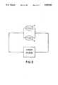
- FIG. 3is an electrical schematic of the device.
- FIG. 1shows a liquid crystal cell 1 behind which a lightbox 2, shown open on its rear, is arranged.
- Two lamps 3, 4 developed as gas-discharge tubesare contained within and are positioned relative to each other by the lightbox 2.
- the gas-discharge tubes of the lamps 3, 4extend in serpentine shape, as shown in FIG. 2. It can be noted that the lamp 4 has first of all a narrow U-shaped region 5, adjoining this a wider U-shaped region 6, and adjoining same again a narrower U-shaped region 7. This makes it possible to arrange the ends of the lamp 4 on a common side of the lightbox 2 so that the lamp 4 has terminals 8, 9 there.
- the lamp 3is of entirely identical shape to the lamp 4.
- a narrow U-shaped region 10 of the lamp 3engages into the wider U-shaped region 6 of the other lamp 4, and a wider U-shaped region 11 of the lamp 3 is arranged over the narrow U-shaped region 7 of the lamp 4.
- the lamp 3is able to have both its terminals 13, 14 disposed on the same side of the lightbox 2.
- the narrow U-shaped region 10 in the case of the lamp 3is less deep than its first narrow U-shaped region 12.
- the narrow U-shaped region 7 of the lamp 4is less deep than its first U-shaped region 5.
- the pattern of the gas-discharge tubesconsisting of a narrow U-shaped region and a wider U-shaped region can repeated as many times as desired. In this way it is possible to illuminate a relatively large display surface.
- One particular advantage of the illuminating deviceis that its structural depth can be kept very small.
- the two lamps 3 and 4are connected electrically in parallel to a source of electric power as shown in FIG. 3.
Landscapes
- Physics & Mathematics (AREA)
- Nonlinear Science (AREA)
- Mathematical Physics (AREA)
- Chemical & Material Sciences (AREA)
- Crystallography & Structural Chemistry (AREA)
- General Physics & Mathematics (AREA)
- Optics & Photonics (AREA)
- Vessels And Coating Films For Discharge Lamps (AREA)
- Devices For Indicating Variable Information By Combining Individual Elements (AREA)
- Non-Portable Lighting Devices Or Systems Thereof (AREA)
- Arrangement Of Elements, Cooling, Sealing, Or The Like Of Lighting Devices (AREA)
Abstract
Description
The present invention relates to an illuminating device for rectangular surface, which device, has two identical lamps connected electrically in parallel, in particular for illuminating a liquid crystal cell from the rear.
Such illuminating devices are customary for indicating instruments in automotive vehicles and are therefore known.
The two lamps, provided for reasons of redundancy should be as identical as possible because of considerations of cost. Upon the failure of one lamp the illuminated surface should still be easily illuminated as uniformly as possible so that the indicating instrument can still be read well. In order to save energy, to be able to operate with lamps which are as weak as possible and to make the illuminating device as compact as possible, they must be arranged relatively close to the surface to be illuminated. In the previously known illuminating device, this necessarily leads to the result that upon failure of a lamp the illumination of the surface is relatively non-uniform.
It is an object of the invention so to develop an illuminating device of the aforementioned kind that, even in the event of the failure of one lamp, the most uniform possible illumination of the surface to be illuminated can be obtained without the device becoming undesirable large and without need to use lamps of undesired brightness.
According to the invention, each lamp (3, 4) is developed as a gas-discharge tube of serpentine shape having at least one narrow U-shaped region (7, 10) and an adjoining wider U-shaped region (6, 11), the two lamps (3, 4) having their U-shaped regions (7, 10; 6, 11) nested within each other in such a manner that in each case the narrow U-shaped region (7, 10) of the one lamp (4 or 3) engages into the wider U-shaped region (6, 11) of the other lamp (4 or 3).
By this internested arrangement of the lamp, a very uniform illumination of the surface to be illuminated can still be obtained even upon the failure of one lamp. Due to the fact that each lamp has a narrow U-shaped region and a wider U-shaped region, the lamps can be arranged nested in each other in a plane despite their identical configuration without regions of the two lamps having to cross each other.
The terminals of the two lamps can, in the case of the illuminating device, be provided for the two lamps on opposite sides of the rear of the illuminating device if, in accordance with one advantageous feature of the invention, each lamp (3, 4) is formed with a sequence of regions comprising, one after the other, the narrow U-shaped region (12, 5), the wider U-shaped region (11, 6) and, adjoining same, once again a narrower U-shaped region (10, 7) which has a course which is shorter than the first narrow U-shaped region (12, 5). By such a course of the tubes a rectangular surface can be illuminated particularly uniformly.
With the above and other objects and advantages in view the present invention will become more clearly understood in connection with the detailed description of a preferred embodiment, when considered with the accompanying drawing, of which:
FIG. 1 is a section through an illuminating device of the invention;
FIG. 2 is a view of the rear side of the illuminating device of FIG. 1; and
FIG. 3 is an electrical schematic of the device.
FIG. 1 shows aliquid crystal cell 1 behind which alightbox 2, shown open on its rear, is arranged. Twolamps lightbox 2.
The gas-discharge tubes of thelamps lamp 4 has first of all a narrow U-shaped region 5, adjoining this awider U-shaped region 6, and adjoining same again a narrower U-shaped region 7. This makes it possible to arrange the ends of thelamp 4 on a common side of thelightbox 2 so that thelamp 4 hasterminals
Thelamp 3 is of entirely identical shape to thelamp 4. A narrow U-shapedregion 10 of thelamp 3 engages into the wider U-shapedregion 6 of theother lamp 4, and awider U-shaped region 11 of thelamp 3 is arranged over the narrow U-shaped region 7 of thelamp 4. By means of an adjoining narrow U-shapedregion 12, thelamp 3 is able to have both itsterminals 13, 14 disposed on the same side of thelightbox 2.
In order to achieve the result that the two gas-discharge tubes are always at the same distance from each other, the narrow U-shapedregion 10 in the case of thelamp 3 is less deep than its first narrow U-shapedregion 12. In corresponding fashion, the narrow U-shaped region 7 of thelamp 4 is less deep than its first U-shaped region 5.
It is clear that the pattern of the gas-discharge tubes consisting of a narrow U-shaped region and a wider U-shaped region can repeated as many times as desired. In this way it is possible to illuminate a relatively large display surface.
One particular advantage of the illuminating device is that its structural depth can be kept very small.
The twolamps
Claims (2)
1. An illuminating device for illuminating a rectangular surface, comprising
two identical lamps connected electrically in parallel; and
means for positioning the lamps in nested arrangement wherein
each lamp is developed as a gas-discharge tube of serpentine shape having at least one narrow U-shaped region and an adjoining wider U-shaped region;
each lamp has its U-shaped regions nested within the U-shaped regions of the other lamp providing for engagement of the narrow U-shaped region of one lamp into the wider U-shaped region of the other lamp; and
each of said lamps has, in sequential order, a first narrow U-shaped region, a wider U-shaped region and, adjoining same, a second narrow U-shaped region which is shorter than the first narrow U-shaped region.
2. A liquid crystal cell assembly comprising:
a liquid crystal cell;
a lightbox disposed behind the cell for directing light through the cell from a back surface of the cell toward a front surface of the cell;
two lamps disposed in the box in a coplanar arrangement for generating the light, each of said lamps having a serpentine shape having U-shaped bends, wherein U-shaped bends of a first of the lamps nest between U-shaped bends of the second of the lamps;
wherein each lamp is developed as a gas-discharge tube of serpentine shape having at least one narrow U-shaped region and an adjoining wider U-shaped region;
each lamp has its U-shaped regions nested within the U-shaped regions of the other lamp providing for engagement of the narrow U-shaped region of one lamp into the wider U-shaped region of the other lamp; and
each of said lamps has, in sequential order, a first narrow U-shaped region, a wider U-shaped region and, adjoining same, a second narrow U-shaped region which is shorter than the first narrow U-shaped region.
Applications Claiming Priority (1)
| Application Number | Priority Date | Filing Date | Title |
|---|---|---|---|
| DE3940506ADE3940506A1 (en) | 1989-12-07 | 1989-12-07 | TWO PARALLEL SWITCHED LIGHTING DEVICES HAVING IDENTICAL LAMPS |
Publications (1)
| Publication Number | Publication Date |
|---|---|
| US5089943Atrue US5089943A (en) | 1992-02-18 |
Family
ID=6395023
Family Applications (1)
| Application Number | Title | Priority Date | Filing Date |
|---|---|---|---|
| US07/626,102Expired - LifetimeUS5089943A (en) | 1989-12-07 | 1990-12-12 | Illuminating device, having two identical lamps connected in parallel |
Country Status (4)
| Country | Link |
|---|---|
| US (1) | US5089943A (en) |
| EP (1) | EP0431246B1 (en) |
| CA (1) | CA2026087C (en) |
| DE (2) | DE3940506A1 (en) |
Cited By (21)
| Publication number | Priority date | Publication date | Assignee | Title |
|---|---|---|---|---|
| US5143433A (en)* | 1991-11-01 | 1992-09-01 | Litton Systems Canada Limited | Night vision backlighting system for liquid crystal displays |
| US5253151A (en)* | 1991-09-30 | 1993-10-12 | Rockwell International Corporation | Luminaire for use in backlighting a liquid crystal display matrix |
| US5434762A (en)* | 1994-04-26 | 1995-07-18 | Sylvan R. Shemitz Associates, Inc. | Compact fluorescent luminaire |
| US5555162A (en)* | 1994-04-26 | 1996-09-10 | Sylvan R. Shemitz Designs, Inc. | Compact fluorescent luminaire |
| US5775801A (en)* | 1996-01-26 | 1998-07-07 | Mccain Traffic Supply, Inc. | Neon traffic signal |
| WO1999025001A1 (en)* | 1997-11-07 | 1999-05-20 | Koninklijke Philips Electronics N.V. | Illumination unit and liquid crystal display device |
| EP0930809A3 (en)* | 1997-12-17 | 2000-02-23 | Juan Roura y Cia., S.A. | Procedure and device for the power supply of fluorescent discharge lamps |
| US6099145A (en)* | 1997-10-30 | 2000-08-08 | Baker Electronics, Inc. | Enhanced MTBF backlight system and related method |
| GB2310078B (en)* | 1996-01-24 | 2000-10-18 | Terence Milner | Lighting device |
| US6168284B1 (en)* | 1998-06-05 | 2001-01-02 | Fritz Gegauf Aktiengesellschaft | Lighting apparatus for a sewing machine |
| USRE37310E1 (en) | 1994-12-06 | 2001-08-07 | Sylvan R. Shemitz Designs, Inc. | Compact fluorescent luminaire |
| US6454431B1 (en) | 1992-05-07 | 2002-09-24 | Cathode Lighting Systems, Inc. | Lighting system |
| US20030142487A1 (en)* | 2002-01-29 | 2003-07-31 | Chi Mei Optoelectronics Corp. | Liquid crystal display device and backlight module thereof |
| US20040240202A1 (en)* | 2002-08-27 | 2004-12-02 | Christian Sauska | Fluorescent lamp providing uniform backlight illumination for displays |
| US20050047174A1 (en)* | 2003-08-29 | 2005-03-03 | Pan John Chungteh | Direct-light illuminating unit of LCD module |
| US20050231980A1 (en)* | 2004-04-20 | 2005-10-20 | Shoichi Ueda | Edge-type backlight module with a curved lamp |
| US20050248938A1 (en)* | 2004-05-04 | 2005-11-10 | Chih-Hsiung Lin | Direct-light illuminating unit of LCD module with light shade devices |
| US20060120102A1 (en)* | 2004-12-08 | 2006-06-08 | Lg. Philips Lcd Co., Ltd. | Direct type backlight unit |
| US20090190066A1 (en)* | 2008-01-24 | 2009-07-30 | Funai Electric Co., Ltd. | Liquid crystal module |
| US20110063274A1 (en)* | 2009-09-14 | 2011-03-17 | Seung-Wan Kim | Backlight assembly and display apparatus having the same |
| US20110075066A1 (en)* | 2009-09-29 | 2011-03-31 | Hitachi Displays, Ltd. | Liquid crystal display device |
Families Citing this family (2)
| Publication number | Priority date | Publication date | Assignee | Title |
|---|---|---|---|---|
| JP4015199B2 (en)* | 1996-09-18 | 2007-11-28 | コーニンクレッカ フィリップス エレクトロニクス エヌ ヴィ | Backlight illumination device |
| TW426203U (en)* | 1996-09-18 | 2001-03-11 | Koninkl Philips Electronics Nv | Backlight luminaire |
Citations (6)
| Publication number | Priority date | Publication date | Assignee | Title |
|---|---|---|---|---|
| US2728845A (en)* | 1951-10-09 | 1955-12-27 | Rowland S Potter | Photographic printer |
| US4748546A (en)* | 1987-02-02 | 1988-05-31 | Allied-Signal Inc. | Fluorescent backlighting unit |
| EP0274269A1 (en)* | 1987-01-05 | 1988-07-13 | General Electric Company | Fluorescent light source for liquid crystal displays |
| GB2207496A (en)* | 1987-07-31 | 1989-02-01 | Japan Aviation Electron | Back light source arrangement for liquid crystal display |
| WO1989005037A1 (en)* | 1987-11-27 | 1989-06-01 | Julius Hartai | Luminous panel |
| US4945350A (en)* | 1985-07-09 | 1990-07-31 | Mitsubishi Denki Kabushiki Kaisha | Liquid crystal display unit |
- 1989
- 1989-12-07DEDE3940506Apatent/DE3940506A1/ennot_activeWithdrawn
- 1990
- 1990-06-12DEDE9090111054Tpatent/DE59001124D1/ennot_activeExpired - Fee Related
- 1990-06-12EPEP90111054Apatent/EP0431246B1/ennot_activeExpired - Lifetime
- 1990-09-24CACA002026087Apatent/CA2026087C/ennot_activeExpired - Fee Related
- 1990-12-12USUS07/626,102patent/US5089943A/ennot_activeExpired - Lifetime
Patent Citations (7)
| Publication number | Priority date | Publication date | Assignee | Title |
|---|---|---|---|---|
| US2728845A (en)* | 1951-10-09 | 1955-12-27 | Rowland S Potter | Photographic printer |
| US4945350A (en)* | 1985-07-09 | 1990-07-31 | Mitsubishi Denki Kabushiki Kaisha | Liquid crystal display unit |
| EP0274269A1 (en)* | 1987-01-05 | 1988-07-13 | General Electric Company | Fluorescent light source for liquid crystal displays |
| US4950053A (en)* | 1987-01-05 | 1990-08-21 | General Electric Company | Multibend fluorescent light source for liquid crystal displays with out of plane lamp electrodes |
| US4748546A (en)* | 1987-02-02 | 1988-05-31 | Allied-Signal Inc. | Fluorescent backlighting unit |
| GB2207496A (en)* | 1987-07-31 | 1989-02-01 | Japan Aviation Electron | Back light source arrangement for liquid crystal display |
| WO1989005037A1 (en)* | 1987-11-27 | 1989-06-01 | Julius Hartai | Luminous panel |
Non-Patent Citations (2)
| Title |
|---|
| Information Display, Band 5, Nr. 11, Nov. 1989, pp. 8 13, New York, U.S.; W. B. Mercer, et al: Fluorescent Backlights for LCDs .* |
| Information Display, Band 5, Nr. 11, Nov. 1989, pp. 8-13, New York, U.S.; W. B. Mercer, et al: "Fluorescent Backlights for LCDs". |
Cited By (29)
| Publication number | Priority date | Publication date | Assignee | Title |
|---|---|---|---|---|
| US5253151A (en)* | 1991-09-30 | 1993-10-12 | Rockwell International Corporation | Luminaire for use in backlighting a liquid crystal display matrix |
| US5143433A (en)* | 1991-11-01 | 1992-09-01 | Litton Systems Canada Limited | Night vision backlighting system for liquid crystal displays |
| US6454431B1 (en) | 1992-05-07 | 2002-09-24 | Cathode Lighting Systems, Inc. | Lighting system |
| US5434762A (en)* | 1994-04-26 | 1995-07-18 | Sylvan R. Shemitz Associates, Inc. | Compact fluorescent luminaire |
| US5555162A (en)* | 1994-04-26 | 1996-09-10 | Sylvan R. Shemitz Designs, Inc. | Compact fluorescent luminaire |
| USRE37310E1 (en) | 1994-12-06 | 2001-08-07 | Sylvan R. Shemitz Designs, Inc. | Compact fluorescent luminaire |
| GB2310078B (en)* | 1996-01-24 | 2000-10-18 | Terence Milner | Lighting device |
| US5775801A (en)* | 1996-01-26 | 1998-07-07 | Mccain Traffic Supply, Inc. | Neon traffic signal |
| US6099145A (en)* | 1997-10-30 | 2000-08-08 | Baker Electronics, Inc. | Enhanced MTBF backlight system and related method |
| US6094015A (en)* | 1997-11-07 | 2000-07-25 | U.S. Philips Corporation | Illumination unit and liquid crystal display device |
| WO1999025001A1 (en)* | 1997-11-07 | 1999-05-20 | Koninklijke Philips Electronics N.V. | Illumination unit and liquid crystal display device |
| EP0930809A3 (en)* | 1997-12-17 | 2000-02-23 | Juan Roura y Cia., S.A. | Procedure and device for the power supply of fluorescent discharge lamps |
| US6168284B1 (en)* | 1998-06-05 | 2001-01-02 | Fritz Gegauf Aktiengesellschaft | Lighting apparatus for a sewing machine |
| US20030142487A1 (en)* | 2002-01-29 | 2003-07-31 | Chi Mei Optoelectronics Corp. | Liquid crystal display device and backlight module thereof |
| US20040240202A1 (en)* | 2002-08-27 | 2004-12-02 | Christian Sauska | Fluorescent lamp providing uniform backlight illumination for displays |
| US6979101B2 (en)* | 2002-08-27 | 2005-12-27 | Lcd Lighting, Inc. | Fluorescent lamp providing uniform backlight illumination for displays |
| US20050047174A1 (en)* | 2003-08-29 | 2005-03-03 | Pan John Chungteh | Direct-light illuminating unit of LCD module |
| US20050231980A1 (en)* | 2004-04-20 | 2005-10-20 | Shoichi Ueda | Edge-type backlight module with a curved lamp |
| US7086753B2 (en)* | 2004-05-04 | 2006-08-08 | Forhouse Corporation | Direct-light illuminating unit of LCD module with light shade devices |
| US20050248938A1 (en)* | 2004-05-04 | 2005-11-10 | Chih-Hsiung Lin | Direct-light illuminating unit of LCD module with light shade devices |
| DE102005030668B4 (en)* | 2004-12-08 | 2009-06-04 | Lg Display Co., Ltd. | Direct backlight unit |
| US20060120102A1 (en)* | 2004-12-08 | 2006-06-08 | Lg. Philips Lcd Co., Ltd. | Direct type backlight unit |
| US7993047B2 (en) | 2004-12-08 | 2011-08-09 | Lg Display Co., Ltd. | Direct type backlight unit |
| US20090190066A1 (en)* | 2008-01-24 | 2009-07-30 | Funai Electric Co., Ltd. | Liquid crystal module |
| JP2009175377A (en)* | 2008-01-24 | 2009-08-06 | Funai Electric Co Ltd | Liquid crystal module |
| US8085361B2 (en)* | 2008-01-24 | 2011-12-27 | Funai Electric Co., Ltd. | Liquid crystal module |
| US20110063274A1 (en)* | 2009-09-14 | 2011-03-17 | Seung-Wan Kim | Backlight assembly and display apparatus having the same |
| US20110075066A1 (en)* | 2009-09-29 | 2011-03-31 | Hitachi Displays, Ltd. | Liquid crystal display device |
| US8269922B2 (en)* | 2009-09-29 | 2012-09-18 | Hitachi Displays, Ltd. | Liquid crystal display device |
Also Published As
| Publication number | Publication date |
|---|---|
| DE59001124D1 (en) | 1993-05-06 |
| CA2026087C (en) | 2000-05-02 |
| EP0431246A1 (en) | 1991-06-12 |
| DE3940506A1 (en) | 1991-06-13 |
| EP0431246B1 (en) | 1993-03-31 |
| CA2026087A1 (en) | 1991-06-08 |
Similar Documents
| Publication | Publication Date | Title |
|---|---|---|
| US5089943A (en) | Illuminating device, having two identical lamps connected in parallel | |
| US4933814A (en) | Planar luminescent device | |
| EP0859933B1 (en) | Backlight luminaire | |
| US4945350A (en) | Liquid crystal display unit | |
| KR100455595B1 (en) | Backlight | |
| EP0140350A2 (en) | Liquid crystal panel display device | |
| US4139957A (en) | Low energy sign illumination system | |
| ES2065743T3 (en) | LINEAR LIGHTING DEVICE AND MOUNTING PART FOR THIS DEVICE. | |
| GB1594819A (en) | Devices for illuminating the dials of display instruments | |
| KR930002926B1 (en) | Panel light emitting devices | |
| JP3279489B2 (en) | LCD lighting system | |
| US4408265A (en) | Lamp, in particular for motor vehicles | |
| US3675242A (en) | Alpha-numeric display | |
| CN1318141A (en) | Longitudinal light source | |
| US7226195B2 (en) | Cold-cathode fluorescent lamp assembly for lighting applications | |
| CN1325961C (en) | Light source unit and illuminator having same | |
| CA2280205C (en) | Multi-lamp assembly for miniature lighting strips | |
| JP3246330B2 (en) | Display device for vehicles | |
| JP4152133B2 (en) | Light emitting device | |
| US3735122A (en) | Lamp fixture and fluorescent lamp therefor | |
| FR2429962A1 (en) | Support for rear lights of automobile - has bulb contacts connected to common bundle of cables with electrical connections at ends of plastics cross member | |
| US1230403A (en) | Changeable electric sign. | |
| JPH0688006U (en) | Lighting equipment | |
| WO1990001182A1 (en) | Display of holograms | |
| JP2601886Y2 (en) | Lighting equipment |
Legal Events
| Date | Code | Title | Description |
|---|---|---|---|
| AS | Assignment | Owner name:VDO ADOLF SCHINDLING AG, GRAFSTRASSE 103, 6000 FRA Free format text:ASSIGNMENT OF ASSIGNORS INTEREST.;ASSIGNOR:WOLFELSCHNEIDER, LOTHAR;REEL/FRAME:005589/0743 Effective date:19910116 Owner name:VDO ADOLF SCHINDLING AG, GERMANY Free format text:ASSIGNMENT OF ASSIGNORS INTEREST;ASSIGNOR:WOLFELSCHNEIDER, LOTHAR;REEL/FRAME:005589/0743 Effective date:19910116 | |
| FEPP | Fee payment procedure | Free format text:PAYOR NUMBER ASSIGNED (ORIGINAL EVENT CODE: ASPN); ENTITY STATUS OF PATENT OWNER: LARGE ENTITY | |
| STCF | Information on status: patent grant | Free format text:PATENTED CASE | |
| AS | Assignment | Owner name:VDO LUFTFAHRTGERATE WERK GMBH Free format text:ASSIGNMENT OF ASSIGNORS INTEREST;ASSIGNOR:VDO ADOLF SCHINDLING AG;REEL/FRAME:006585/0296 Effective date:19930303 | |
| FPAY | Fee payment | Year of fee payment:4 | |
| FPAY | Fee payment | Year of fee payment:8 | |
| FPAY | Fee payment | Year of fee payment:12 |