US5088972A - Folding and crimping apparatus - Google Patents
Folding and crimping apparatusDownload PDFInfo
- Publication number
- US5088972A US5088972AUS07/430,861US43086189AUS5088972AUS 5088972 AUS5088972 AUS 5088972AUS 43086189 AUS43086189 AUS 43086189AUS 5088972 AUS5088972 AUS 5088972A
- Authority
- US
- United States
- Prior art keywords
- strips
- sheet material
- barrier
- strip
- confined area
- Prior art date
- Legal status (The legal status is an assumption and is not a legal conclusion. Google has not performed a legal analysis and makes no representation as to the accuracy of the status listed.)
- Expired - Lifetime
Links
- 238000002788crimpingMethods0.000titleclaimsabstractdescription42
- 239000000463materialSubstances0.000claimsabstractdescription130
- 230000004888barrier functionEffects0.000claimsabstractdescription60
- 238000005520cutting processMethods0.000claimsabstractdescription52
- 239000003086colorantSubstances0.000claimsdescription10
- 230000001105regulatory effectEffects0.000claimsdescription9
- 238000012856packingMethods0.000claimsdescription8
- 239000011111cardboardSubstances0.000claimsdescription7
- 230000005484gravityEffects0.000claimsdescription5
- 230000000717retained effectEffects0.000claimsdescription3
- 239000011087paperboardSubstances0.000claimsdescription2
- 230000005465channelingEffects0.000claims3
- 238000000034methodMethods0.000abstractdescription16
- 239000005022packaging materialSubstances0.000abstractdescription15
- 238000003780insertionMethods0.000abstractdescription4
- 230000037431insertionEffects0.000abstractdescription4
- 239000000123paperSubstances0.000description21
- 244000105624Arachis hypogaeaSpecies0.000description17
- 235000020232peanutNutrition0.000description17
- 229920006328StyrofoamPolymers0.000description13
- 239000008261styrofoamSubstances0.000description13
- 238000010008shearingMethods0.000description12
- 238000004806packaging method and processMethods0.000description9
- 230000008901benefitEffects0.000description5
- 230000000694effectsEffects0.000description5
- 230000004048modificationEffects0.000description5
- 238000012986modificationMethods0.000description5
- 230000036961partial effectEffects0.000description5
- 230000006835compressionEffects0.000description4
- 238000007906compressionMethods0.000description4
- 239000003814drugSubstances0.000description4
- 229940079593drugDrugs0.000description4
- 235000013305foodNutrition0.000description4
- 238000013461designMethods0.000description3
- 238000004519manufacturing processMethods0.000description3
- 235000014571nutsNutrition0.000description3
- 230000035939shockEffects0.000description3
- 241000251468ActinopterygiiSpecies0.000description2
- 229920002799BoPETPolymers0.000description2
- 239000005041Mylar™Substances0.000description2
- 230000009286beneficial effectEffects0.000description2
- 239000000203mixtureSubstances0.000description2
- 230000008569processEffects0.000description2
- 230000002829reductive effectEffects0.000description2
- 239000011800void materialSubstances0.000description2
- 239000002023woodSubstances0.000description2
- 229920004142LEXAN™Polymers0.000description1
- 239000004418LexanSubstances0.000description1
- 241001465754MetazoaSpecies0.000description1
- 229910000831SteelInorganic materials0.000description1
- 229910000746Structural steelInorganic materials0.000description1
- 239000000654additiveSubstances0.000description1
- 230000004075alterationEffects0.000description1
- XAGFODPZIPBFFR-UHFFFAOYSA-NaluminiumChemical compound[Al]XAGFODPZIPBFFR-UHFFFAOYSA-N0.000description1
- 229910052782aluminiumInorganic materials0.000description1
- 230000015572biosynthetic processEffects0.000description1
- 239000013590bulk materialSubstances0.000description1
- 230000015556catabolic processEffects0.000description1
- 238000005056compactionMethods0.000description1
- 239000002361compostSubstances0.000description1
- 238000010276constructionMethods0.000description1
- 239000003337fertilizerSubstances0.000description1
- 239000000945fillerSubstances0.000description1
- 239000012530fluidSubstances0.000description1
- 239000011521glassSubstances0.000description1
- 230000000670limiting effectEffects0.000description1
- 239000008188pelletSubstances0.000description1
- 239000004033plasticSubstances0.000description1
- 230000000135prohibitive effectEffects0.000description1
- 230000001681protective effectEffects0.000description1
- 239000002994raw materialSubstances0.000description1
- 238000005096rolling processMethods0.000description1
- 238000007789sealingMethods0.000description1
- 239000010959steelSubstances0.000description1
- 239000002341toxic gasSubstances0.000description1
- 239000012780transparent materialSubstances0.000description1
- 239000002699waste materialSubstances0.000description1
Images


Classifications
- B—PERFORMING OPERATIONS; TRANSPORTING
- B31—MAKING ARTICLES OF PAPER, CARDBOARD OR MATERIAL WORKED IN A MANNER ANALOGOUS TO PAPER; WORKING PAPER, CARDBOARD OR MATERIAL WORKED IN A MANNER ANALOGOUS TO PAPER
- B31D—MAKING ARTICLES OF PAPER, CARDBOARD OR MATERIAL WORKED IN A MANNER ANALOGOUS TO PAPER, NOT PROVIDED FOR IN SUBCLASSES B31B OR B31C
- B31D5/00—Multiple-step processes for making three-dimensional articles ; Making three-dimensional articles
- B31D5/0039—Multiple-step processes for making three-dimensional articles ; Making three-dimensional articles for making dunnage or cushion pads
- B31D5/006—Multiple-step processes for making three-dimensional articles ; Making three-dimensional articles for making dunnage or cushion pads including controlled deformation of flat material, e.g. pleating, corrugating or embossing
- B—PERFORMING OPERATIONS; TRANSPORTING
- B31—MAKING ARTICLES OF PAPER, CARDBOARD OR MATERIAL WORKED IN A MANNER ANALOGOUS TO PAPER; WORKING PAPER, CARDBOARD OR MATERIAL WORKED IN A MANNER ANALOGOUS TO PAPER
- B31B—MAKING CONTAINERS OF PAPER, CARDBOARD OR MATERIAL WORKED IN A MANNER ANALOGOUS TO PAPER
- B31B50/00—Making rigid or semi-rigid containers, e.g. boxes or cartons
- B31B50/14—Cutting, e.g. perforating, punching, slitting or trimming
- B—PERFORMING OPERATIONS; TRANSPORTING
- B26—HAND CUTTING TOOLS; CUTTING; SEVERING
- B26D—CUTTING; DETAILS COMMON TO MACHINES FOR PERFORATING, PUNCHING, CUTTING-OUT, STAMPING-OUT OR SEVERING
- B26D1/00—Cutting through work characterised by the nature or movement of the cutting member or particular materials not otherwise provided for; Apparatus or machines therefor; Cutting members therefor
- B26D1/01—Cutting through work characterised by the nature or movement of the cutting member or particular materials not otherwise provided for; Apparatus or machines therefor; Cutting members therefor involving a cutting member which does not travel with the work
- B26D1/12—Cutting through work characterised by the nature or movement of the cutting member or particular materials not otherwise provided for; Apparatus or machines therefor; Cutting members therefor involving a cutting member which does not travel with the work having a cutting member moving about an axis
- B26D1/14—Cutting through work characterised by the nature or movement of the cutting member or particular materials not otherwise provided for; Apparatus or machines therefor; Cutting members therefor involving a cutting member which does not travel with the work having a cutting member moving about an axis with a circular cutting member, e.g. disc cutter
- B26D1/24—Cutting through work characterised by the nature or movement of the cutting member or particular materials not otherwise provided for; Apparatus or machines therefor; Cutting members therefor involving a cutting member which does not travel with the work having a cutting member moving about an axis with a circular cutting member, e.g. disc cutter coacting with another disc cutter
- B26D1/245—Cutting through work characterised by the nature or movement of the cutting member or particular materials not otherwise provided for; Apparatus or machines therefor; Cutting members therefor involving a cutting member which does not travel with the work having a cutting member moving about an axis with a circular cutting member, e.g. disc cutter coacting with another disc cutter for thin material, e.g. for sheets, strips or the like
- B—PERFORMING OPERATIONS; TRANSPORTING
- B26—HAND CUTTING TOOLS; CUTTING; SEVERING
- B26D—CUTTING; DETAILS COMMON TO MACHINES FOR PERFORATING, PUNCHING, CUTTING-OUT, STAMPING-OUT OR SEVERING
- B26D1/00—Cutting through work characterised by the nature or movement of the cutting member or particular materials not otherwise provided for; Apparatus or machines therefor; Cutting members therefor
- B26D1/01—Cutting through work characterised by the nature or movement of the cutting member or particular materials not otherwise provided for; Apparatus or machines therefor; Cutting members therefor involving a cutting member which does not travel with the work
- B26D1/12—Cutting through work characterised by the nature or movement of the cutting member or particular materials not otherwise provided for; Apparatus or machines therefor; Cutting members therefor involving a cutting member which does not travel with the work having a cutting member moving about an axis
- B26D1/25—Cutting through work characterised by the nature or movement of the cutting member or particular materials not otherwise provided for; Apparatus or machines therefor; Cutting members therefor involving a cutting member which does not travel with the work having a cutting member moving about an axis with a non-circular cutting member
- B26D1/34—Cutting through work characterised by the nature or movement of the cutting member or particular materials not otherwise provided for; Apparatus or machines therefor; Cutting members therefor involving a cutting member which does not travel with the work having a cutting member moving about an axis with a non-circular cutting member moving about an axis parallel to the line of cut
- B26D1/40—Cutting through work characterised by the nature or movement of the cutting member or particular materials not otherwise provided for; Apparatus or machines therefor; Cutting members therefor involving a cutting member which does not travel with the work having a cutting member moving about an axis with a non-circular cutting member moving about an axis parallel to the line of cut and coacting with a rotary member
- B26D1/405—Cutting through work characterised by the nature or movement of the cutting member or particular materials not otherwise provided for; Apparatus or machines therefor; Cutting members therefor involving a cutting member which does not travel with the work having a cutting member moving about an axis with a non-circular cutting member moving about an axis parallel to the line of cut and coacting with a rotary member for thin material, e.g. for sheets, strips or the like
- B—PERFORMING OPERATIONS; TRANSPORTING
- B26—HAND CUTTING TOOLS; CUTTING; SEVERING
- B26D—CUTTING; DETAILS COMMON TO MACHINES FOR PERFORATING, PUNCHING, CUTTING-OUT, STAMPING-OUT OR SEVERING
- B26D9/00—Cutting apparatus combined with punching or perforating apparatus or with dissimilar cutting apparatus
- B—PERFORMING OPERATIONS; TRANSPORTING
- B31—MAKING ARTICLES OF PAPER, CARDBOARD OR MATERIAL WORKED IN A MANNER ANALOGOUS TO PAPER; WORKING PAPER, CARDBOARD OR MATERIAL WORKED IN A MANNER ANALOGOUS TO PAPER
- B31F—MECHANICAL WORKING OR DEFORMATION OF PAPER, CARDBOARD OR MATERIAL WORKED IN A MANNER ANALOGOUS TO PAPER
- B31F5/00—Attaching together sheets, strips or webs; Reinforcing edges
- B31F5/005—Attaching together sheets, strips or webs; Reinforcing edges by folding
- B—PERFORMING OPERATIONS; TRANSPORTING
- B65—CONVEYING; PACKING; STORING; HANDLING THIN OR FILAMENTARY MATERIAL
- B65D—CONTAINERS FOR STORAGE OR TRANSPORT OF ARTICLES OR MATERIALS, e.g. BAGS, BARRELS, BOTTLES, BOXES, CANS, CARTONS, CRATES, DRUMS, JARS, TANKS, HOPPERS, FORWARDING CONTAINERS; ACCESSORIES, CLOSURES, OR FITTINGS THEREFOR; PACKAGING ELEMENTS; PACKAGES
- B65D81/00—Containers, packaging elements, or packages, for contents presenting particular transport or storage problems, or adapted to be used for non-packaging purposes after removal of contents
- B65D81/02—Containers, packaging elements, or packages, for contents presenting particular transport or storage problems, or adapted to be used for non-packaging purposes after removal of contents specially adapted to protect contents from mechanical damage
- B65D81/05—Containers, packaging elements, or packages, for contents presenting particular transport or storage problems, or adapted to be used for non-packaging purposes after removal of contents specially adapted to protect contents from mechanical damage maintaining contents at spaced relation from package walls, or from other contents
- B65D81/09—Containers, packaging elements, or packages, for contents presenting particular transport or storage problems, or adapted to be used for non-packaging purposes after removal of contents specially adapted to protect contents from mechanical damage maintaining contents at spaced relation from package walls, or from other contents using flowable discrete elements of shock-absorbing material, e.g. pellets or popcorn
- B—PERFORMING OPERATIONS; TRANSPORTING
- B31—MAKING ARTICLES OF PAPER, CARDBOARD OR MATERIAL WORKED IN A MANNER ANALOGOUS TO PAPER; WORKING PAPER, CARDBOARD OR MATERIAL WORKED IN A MANNER ANALOGOUS TO PAPER
- B31D—MAKING ARTICLES OF PAPER, CARDBOARD OR MATERIAL WORKED IN A MANNER ANALOGOUS TO PAPER, NOT PROVIDED FOR IN SUBCLASSES B31B OR B31C
- B31D2205/00—Multiple-step processes for making three-dimensional articles
- B31D2205/0005—Multiple-step processes for making three-dimensional articles for making dunnage or cushion pads
- B31D2205/0011—Multiple-step processes for making three-dimensional articles for making dunnage or cushion pads including particular additional operations
- B31D2205/0058—Cutting; Individualising the final products
- B—PERFORMING OPERATIONS; TRANSPORTING
- B31—MAKING ARTICLES OF PAPER, CARDBOARD OR MATERIAL WORKED IN A MANNER ANALOGOUS TO PAPER; WORKING PAPER, CARDBOARD OR MATERIAL WORKED IN A MANNER ANALOGOUS TO PAPER
- B31D—MAKING ARTICLES OF PAPER, CARDBOARD OR MATERIAL WORKED IN A MANNER ANALOGOUS TO PAPER, NOT PROVIDED FOR IN SUBCLASSES B31B OR B31C
- B31D2205/00—Multiple-step processes for making three-dimensional articles
- B31D2205/0005—Multiple-step processes for making three-dimensional articles for making dunnage or cushion pads
- B31D2205/0011—Multiple-step processes for making three-dimensional articles for making dunnage or cushion pads including particular additional operations
- B31D2205/007—Delivering
- Y—GENERAL TAGGING OF NEW TECHNOLOGICAL DEVELOPMENTS; GENERAL TAGGING OF CROSS-SECTIONAL TECHNOLOGIES SPANNING OVER SEVERAL SECTIONS OF THE IPC; TECHNICAL SUBJECTS COVERED BY FORMER USPC CROSS-REFERENCE ART COLLECTIONS [XRACs] AND DIGESTS
- Y10—TECHNICAL SUBJECTS COVERED BY FORMER USPC
- Y10S—TECHNICAL SUBJECTS COVERED BY FORMER USPC CROSS-REFERENCE ART COLLECTIONS [XRACs] AND DIGESTS
- Y10S493/00—Manufacturing container or tube from paper; or other manufacturing from a sheet or web
- Y10S493/967—Dunnage, wadding, stuffing, or filling excelsior
- Y—GENERAL TAGGING OF NEW TECHNOLOGICAL DEVELOPMENTS; GENERAL TAGGING OF CROSS-SECTIONAL TECHNOLOGIES SPANNING OVER SEVERAL SECTIONS OF THE IPC; TECHNICAL SUBJECTS COVERED BY FORMER USPC CROSS-REFERENCE ART COLLECTIONS [XRACs] AND DIGESTS
- Y10—TECHNICAL SUBJECTS COVERED BY FORMER USPC
- Y10S—TECHNICAL SUBJECTS COVERED BY FORMER USPC CROSS-REFERENCE ART COLLECTIONS [XRACs] AND DIGESTS
- Y10S493/00—Manufacturing container or tube from paper; or other manufacturing from a sheet or web
- Y10S493/968—Structural shape
- Y—GENERAL TAGGING OF NEW TECHNOLOGICAL DEVELOPMENTS; GENERAL TAGGING OF CROSS-SECTIONAL TECHNOLOGIES SPANNING OVER SEVERAL SECTIONS OF THE IPC; TECHNICAL SUBJECTS COVERED BY FORMER USPC CROSS-REFERENCE ART COLLECTIONS [XRACs] AND DIGESTS
- Y10—TECHNICAL SUBJECTS COVERED BY FORMER USPC
- Y10T—TECHNICAL SUBJECTS COVERED BY FORMER US CLASSIFICATION
- Y10T428/00—Stock material or miscellaneous articles
- Y10T428/24—Structurally defined web or sheet [e.g., overall dimension, etc.]
- Y10T428/24355—Continuous and nonuniform or irregular surface on layer or component [e.g., roofing, etc.]
- Y10T428/24446—Wrinkled, creased, crinkled or creped
- Y10T428/24455—Paper
- Y10T428/24463—Plural paper components
- Y—GENERAL TAGGING OF NEW TECHNOLOGICAL DEVELOPMENTS; GENERAL TAGGING OF CROSS-SECTIONAL TECHNOLOGIES SPANNING OVER SEVERAL SECTIONS OF THE IPC; TECHNICAL SUBJECTS COVERED BY FORMER USPC CROSS-REFERENCE ART COLLECTIONS [XRACs] AND DIGESTS
- Y10—TECHNICAL SUBJECTS COVERED BY FORMER USPC
- Y10T—TECHNICAL SUBJECTS COVERED BY FORMER US CLASSIFICATION
- Y10T428/00—Stock material or miscellaneous articles
- Y10T428/24—Structurally defined web or sheet [e.g., overall dimension, etc.]
- Y10T428/24628—Nonplanar uniform thickness material
- Y10T428/24636—Embodying mechanically interengaged strand[s], strand-portion[s] or strand-like strip[s] [e.g., weave, knit, etc.]
- Y—GENERAL TAGGING OF NEW TECHNOLOGICAL DEVELOPMENTS; GENERAL TAGGING OF CROSS-SECTIONAL TECHNOLOGIES SPANNING OVER SEVERAL SECTIONS OF THE IPC; TECHNICAL SUBJECTS COVERED BY FORMER USPC CROSS-REFERENCE ART COLLECTIONS [XRACs] AND DIGESTS
- Y10—TECHNICAL SUBJECTS COVERED BY FORMER USPC
- Y10T—TECHNICAL SUBJECTS COVERED BY FORMER US CLASSIFICATION
- Y10T428/00—Stock material or miscellaneous articles
- Y10T428/24—Structurally defined web or sheet [e.g., overall dimension, etc.]
- Y10T428/24628—Nonplanar uniform thickness material
- Y10T428/24669—Aligned or parallel nonplanarities
- Y10T428/24694—Parallel corrugations
- Y10T428/24711—Plural corrugated components
- Y—GENERAL TAGGING OF NEW TECHNOLOGICAL DEVELOPMENTS; GENERAL TAGGING OF CROSS-SECTIONAL TECHNOLOGIES SPANNING OVER SEVERAL SECTIONS OF THE IPC; TECHNICAL SUBJECTS COVERED BY FORMER USPC CROSS-REFERENCE ART COLLECTIONS [XRACs] AND DIGESTS
- Y10—TECHNICAL SUBJECTS COVERED BY FORMER USPC
- Y10T—TECHNICAL SUBJECTS COVERED BY FORMER US CLASSIFICATION
- Y10T428/00—Stock material or miscellaneous articles
- Y10T428/24—Structurally defined web or sheet [e.g., overall dimension, etc.]
- Y10T428/24802—Discontinuous or differential coating, impregnation or bond [e.g., artwork, printing, retouched photograph, etc.]
- Y10T428/2481—Discontinuous or differential coating, impregnation or bond [e.g., artwork, printing, retouched photograph, etc.] including layer of mechanically interengaged strands, strand-portions or strand-like strips
- Y—GENERAL TAGGING OF NEW TECHNOLOGICAL DEVELOPMENTS; GENERAL TAGGING OF CROSS-SECTIONAL TECHNOLOGIES SPANNING OVER SEVERAL SECTIONS OF THE IPC; TECHNICAL SUBJECTS COVERED BY FORMER USPC CROSS-REFERENCE ART COLLECTIONS [XRACs] AND DIGESTS
- Y10—TECHNICAL SUBJECTS COVERED BY FORMER USPC
- Y10T—TECHNICAL SUBJECTS COVERED BY FORMER US CLASSIFICATION
- Y10T428/00—Stock material or miscellaneous articles
- Y10T428/24—Structurally defined web or sheet [e.g., overall dimension, etc.]
- Y10T428/24802—Discontinuous or differential coating, impregnation or bond [e.g., artwork, printing, retouched photograph, etc.]
- Y10T428/24934—Discontinuous or differential coating, impregnation or bond [e.g., artwork, printing, retouched photograph, etc.] including paper layer
- Y—GENERAL TAGGING OF NEW TECHNOLOGICAL DEVELOPMENTS; GENERAL TAGGING OF CROSS-SECTIONAL TECHNOLOGIES SPANNING OVER SEVERAL SECTIONS OF THE IPC; TECHNICAL SUBJECTS COVERED BY FORMER USPC CROSS-REFERENCE ART COLLECTIONS [XRACs] AND DIGESTS
- Y10—TECHNICAL SUBJECTS COVERED BY FORMER USPC
- Y10T—TECHNICAL SUBJECTS COVERED BY FORMER US CLASSIFICATION
- Y10T428/00—Stock material or miscellaneous articles
- Y10T428/249921—Web or sheet containing structurally defined element or component
- Y10T428/249922—Embodying intertwined or helical component[s]
- Y—GENERAL TAGGING OF NEW TECHNOLOGICAL DEVELOPMENTS; GENERAL TAGGING OF CROSS-SECTIONAL TECHNOLOGIES SPANNING OVER SEVERAL SECTIONS OF THE IPC; TECHNICAL SUBJECTS COVERED BY FORMER USPC CROSS-REFERENCE ART COLLECTIONS [XRACs] AND DIGESTS
- Y10—TECHNICAL SUBJECTS COVERED BY FORMER USPC
- Y10T—TECHNICAL SUBJECTS COVERED BY FORMER US CLASSIFICATION
- Y10T428/00—Stock material or miscellaneous articles
- Y10T428/29—Coated or structually defined flake, particle, cell, strand, strand portion, rod, filament, macroscopic fiber or mass thereof
- Y10T428/2904—Staple length fiber
- Y10T428/2909—Nonlinear [e.g., crimped, coiled, etc.]
- Y—GENERAL TAGGING OF NEW TECHNOLOGICAL DEVELOPMENTS; GENERAL TAGGING OF CROSS-SECTIONAL TECHNOLOGIES SPANNING OVER SEVERAL SECTIONS OF THE IPC; TECHNICAL SUBJECTS COVERED BY FORMER USPC CROSS-REFERENCE ART COLLECTIONS [XRACs] AND DIGESTS
- Y10—TECHNICAL SUBJECTS COVERED BY FORMER USPC
- Y10T—TECHNICAL SUBJECTS COVERED BY FORMER US CLASSIFICATION
- Y10T428/00—Stock material or miscellaneous articles
- Y10T428/29—Coated or structually defined flake, particle, cell, strand, strand portion, rod, filament, macroscopic fiber or mass thereof
- Y10T428/2913—Rod, strand, filament or fiber
- Y10T428/2922—Nonlinear [e.g., crimped, coiled, etc.]
- Y10T428/2924—Composite
Definitions
- the present inventionrelates to improvements in a paper shredding device. More particularly, this invention relates to apparatus and methods for folding and crimping shredded strips of sheet material into selected lengths of interlocking, bulk, packaging material.
- Styrofoam pellets or peanutsare commonly used within the wholesale and retail industries as bulk packaging material.
- the peanutsare used to position a product away from the interior sides of a container and fill the empty space located therebetween.
- the peanutsare intended to protect the packaged product against the impact of a blow or other mistreatment.
- Dispensing styrofoam peanutsdoes not require a great degree of sophistication.
- the peanutsare simply gravity fed from large retainer bins into the empty spaces within a packaging container.
- styrofoam peanutshave many drawbacks. For example, if styrofoam peanuts are used to protect a heavy object placed within a container, and such package is jostled and shaken, the object usually gravitates toward the bottom of the container and the peanuts float upward. Eventually the object comes to rest against the base or side of the container and damage to the object may occur. The light weight of styrofoam peanuts also allows them to be easily blown by the wind and scattered.
- styrofoam peanutsare extremely difficult to dispose of and destroy after use.
- this nonbiodegradable productwhich emits toxic gases if burned, styrofoam peanuts present a major threat to the environment and are being banned from an increasing number of communities.
- Styrofoam peanutsare also dangerous to children and to wildlife who often mistake them as food and consequently ingest them. Styrofoam peanuts are not digestible and cause a major source of tracheal blockage in children.
- Shredded paperusually lays flat within the container and a very large amount of paper is required to provide the bulk needed to fill the voids and to protect the contained object. To provide such a large amount of shredded paper is often cost prohibitive and, following its use, such voluminous amounts of paper must be disposed. In addition, the shock absorbency of flat shredded paper is minimal.
- a further objectis to provide apparatus and methods for producing large quantities of folded and crimped, shredded strips of sheet material which: avoid interference with the otherwise normal operation of a conventional shredding device; does not require permanent modification of the shredding device's structure, or defacement or mutilation thereof; and may be used on any commercial shredding device, irrespective of its design or general configuration.
- a still further objectis to provide apparatus and methods for a commercial shredding device which allows for quick and easy adjustment of the device to selectively extend or shorten the length of the shredded, folded, and crimped strips of sheet material into segment lengths which would otherwise be commercially impossible, and to do so without requiring modification of the device's structure, extensive knowledge of the device's mechanics, or any careful or critical attention by the operator.
- Another objectis to produce a series of folded, interlocking strips of bulk packaging material which are produced from colored sheet material and may be made from a large variety of different colors or controlled combinations of colors.
- Another objectis to produce the folded, interlocking strips from biodegradable pulp materials such as from paper, cardboard, and the like, the composition of which may be edible and is approved by the U.S. Federal Food and Drug Administration (FDA) for use in packaging edible products.
- biodegradable pulp materialssuch as from paper, cardboard, and the like, the composition of which may be edible and is approved by the U.S. Federal Food and Drug Administration (FDA) for use in packaging edible products.
- FDAFederal Food and Drug Administration
- the present inventionachieves these general and specific objects and presents new apparatus and methods for producing a bulk packaging material which incorporates therein the beneficial features of both styrofoam peanuts and shredded paper.
- the present inventionalso overcomes each of the previously mentioned disadvantages.
- this inventionprovides apparatus and methods for rapidly producing large quantities of bulk packaging material comprising folded and crimped, interlocking strips of sheet material which may:
- (b)be produced with selectable lengths, smaller lengths capable of being gravity fed into a container to fill the void left by the banning of styrofoam peanuts, larger lengths capable of being wrapped around a product to provide a secure protective cushion;
- (d)be manufactured from biodegradable material, such as pulp material (i.e., paper, cardboard, or the like); and
- the inventioncomprises an attachment for a commercial shredding machine or device.
- the attachmentis a simple, compact, rugged, inexpensive, movable barrier which is easily attached and employed.
- the present inventiondoes not necessarily require the defacement or alteration of the shredding device's structure.
- the attachmentmodifies the shredding device to cause a sheet material, such as mylar, paper, cardboard, or the like, which is fed therethrough, to be impacted or impelled against a barrier after having passed through a series of cutting blades in the shredding device.
- the barriercauses the shredded sheet material to become controllably jammed between the barrier and the cutting blades.
- the continued rotation of the cutting bladesforces additional amounts of sheet material into the shredding machine and cutting blades.
- each shredded strip of sheet materialis folded against itself in a relatively controlled manner, thereby, repetitively folding and crimping or creasing each strip and compacting it within a confined space or area against a remaining dam of jammed shredded strips.
- the resulting effectis the folding or crimping of each cut strip into an accordion-shaped mass.
- the confined areapreferably is located near an exit opening of the shredding device through which the shredded strips pass.
- a pressure sensitive gateopens to allow the escape of a portion of the jammed strips.
- the gatecontrollably maintains the confinement of a remaining portion of jammed strips within the confined area. The gate thus allows the continuation of additional lengths of shredded sheet material to be folded and pressed against the remaining dam of jammed strips without the modified device actually becoming jammed to the point of requiring servicing.
- the means for controllably jamming the paper within the confined areamay comprise a simple, movable barrier which is placed near the exit opening of the shredding device.
- the barriercauses the shredded strips of sheet material to temporarily remain within a confined area located between the barrier and the cutting blades of the shredding device.
- the confined areamay be of a fairly small or large volume, the boundaries of which are initially defined by the barrier, the cutting blades, and possibly a lower, upper, and side support elements. After a partial dam of shredded strips has been achieved, the dam itself further limits the volume of space remaining within the confined area. As long as a partial dam of shredded strips remains within the confined area, such shredded strips serve the purpose of the moveable barrier, and may even eliminate the need for continued use of the gate barrier.
- the barriercomprises a movable gate which is urged toward a closed position.
- the gateserves to hinder the exit of the shredded strips and to confine the strips into a partially jammed state.
- the expelling force of the shredding deviceforces the shredded strips into the confined area.
- the gateis urged open to allow a portion of the folded and crimped strips to escape.
- a weighted, hinged gatemay be used.
- Other embodimentsinclude the use of a pivotal gate which is urged toward its closed position by a spring or by a hydraulic or pneumatic piston.
- the stripsmay be deposited within a receiving bin.
- the compressed state of the folded and crimped stripsmay be maintained by forcing the strips to travel through a confined conduit.
- a second cutting device or shearing devicemay be located at some point along the length of the confined conduit or at the end thereof. The shearing device may be engaged to cut or shear the compacted, folded, and crimped strips into segments.
- the shearing devicemay be activated at preselectable time intervals to shear, cut, or dissect the compressed, crimped strips traveling within the confined conduit into various segment lengths. This process enables the formation of crimped strips of material having any desired length from 100 foot lengths or greater to segments of one or two inches or smaller.
- a plurality of layered, shredded, folded and crimped strips of sheet materialmay be cut into short segments that are bonded at each terminal end thereof. These shorter segments serve very well to replace the use of styrofoam peanuts. Such shorter segments may also be used in existing gravity feed systems.
- Longer lengths of the shredded, folded and crimped stripsmay be used for decorative effects at parties and/or window or room displays.
- the longer lengths of the folded stripsmay also be used as bulk padding and packing material.
- the object to be protectedmay be liberally and literally wrapped within multiple lengths of interconnecting and interlocking folded and crimped, shredded strips.
- the stripsinterlock with one another, the strips hold their form and greatly increase the volume of space they occupy. Thus, the use of a smaller amount of paper is required to protect a particularly packaged object.
- the shock absorbency of the packing materialis also substantially increased, since the impact of a blow is disbursed throughout each interacting ridge or web of the interconnecting folded strips.
- the folded and crimped status of the strips of the present inventionallows for a substantially greater degree of interlocking effect and shock absorbency than do the kinked strips described in Lee ('567).
- the longer lengths of crimped, shredded stripsmay be placed within a retainer bin or hopper and a selected amount of bulk packaging material may be torn therefrom. This enables an operator to use an exact amount of desired packaging material, and thereby reduce waste.
- Another important, added benefit of the present inventionis the ability to use a variety of colors in the production of the shredded, folded and crimped strips. This enables the inventor to produce bulk packaging material of the present invention having the chosen colors of a particular store, company, or corporation. This is accomplished by simply using a sheet material having the desired color.
- a combination of colorsmay also be used.
- Two or more differently colored sheets of materialmay be passed into the shredding machine to produce a variety of color combinations. The only limiting factor is the capacity of the shredding machine. For example, a first percentage of one color (such as 23% of dark blue) and a second percentage of another color (such as 77% of light blue) may be used.
- a first percentage of one colorsuch as 23% of dark blue
- a second percentage of another colorsuch as 77% of light blue
- Printed, embossed, or any other means of identificationmay also be affixed to the sheet material which is shredded.
- printinglocates the printed matter longitudinally along each length of shredded strip.
- a store, company or corporationmay have its name, logo, trademark, or other subject matter, listed along each individually crimped strip.
- Another important benefitis that recyclable, biodegradable sheet material may be used.
- pulp materialssuch as paper and/or cardboard which breakdown and decompose quickly, the detriment to the environment by disposal of such material is minimized.
- the environmentmay even be enhanced by the discarding of such packaging material.
- fertilizers or other beneficial additivesmay be incorporated into the sheet material.
- Edible sheet material and sheet materialwhich has been approved by the U.S. Food and Drug Administration (FDA) for use in packaging edible, or at least consumable, products may also be used.
- FDAFood and Drug Administration
- crimped sheet materialincludes using it as bulk material for starting worm composts and/or animal bedding.
- the apparatus which produces such a universal bulk packaging materialis inexpensive, and is easily manufactured. Operation of the apparatus is also extremely simplistic and may be accomplished by an unskilled worker.
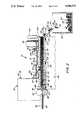
- FIG. 1is a partial, cross-sectional, side elevational view of the preferred embodiment of the present invention wherein a hinged gate is shown located in a closed position to serve as a barrier.
- FIG. 1ais a fragmentary top view of the preferred embodiment as seen along line Ia--Ia of FIG. 1.
- FIG. 2is a partial, cross-sectional, side elevational view of the apparatus shown in FIG. 1, wherein the gate is urged away from its closed position.
- FIG. 3is an enlarged, partial, cross-sectional, side elevational view of the gate in its closed position.
- FIG. 4is an enlarged, fragmentary, cross-sectional, front elevational view taken along line IV--IV in FIG. 1.
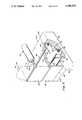
- FIG. 5is an enlarged, fragmentary, isometric view of the preferred embodiment shown in FIG. 1.
- FIG. 6is an isometric view of a plurality of bonded segments of folded, crimped, interlocking strips of shredded sheet material which is a product of the present invention.
- FIG. 7is an isometric view of strips of shredded paper as found in the prior art.
- FIG. 8is an isometric view of a plurality of folded, crimped, interlocking strips of shredded sheet material as produced by present invention.
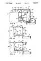
- FIG. 9an isometric view of shredded strips of sheet material passing through an exit opening of a shredding device and entering a confined area located between the shredding device and a barrier, such as a gate having pivotal ability.
- FIG. 10is a schematic, fragmentary, elevational view of the shredding device and barrier shown in FIG. 9, wherein the shredded strips are illustrated as initially entering the confined area.
- FIG. 11is a schematic, fragmentary, elevational view of the shredding device and barrier shown in FIGS. 9 and 10, wherein the shredded strips are becoming dammed between the pivotal gate and the exit opening of the shredding device.
- FIG. 12is a schematic, fragmentary, elevational view of the shredding device, wherein the pivotal gate is partially deflected to allow a controlled portion of the folded and crimped strips of sheet material to pass thereby and be deposited within a receiving bin.
- FIG. 13is a schematic, fragmentary, elevational view of the present invention, wherein a cutting or shearing device is illustrated as cutting the folded and crimped strips into segments of a desired length.
- strips 20may be cut into elongate strips 20.
- Strips 20do not provide very much resiliency or forgiveness when subjected to a blow or other mistreatment. A large number of strips 20 are required to fill a given empty space.
- FIG. 8illustrates a plurality of shredded, elongate, interconnecting strips 22 which have been folded and crimped using the apparatus and methods as taught herein.
- the folds within crimped strips 22interlock with one another to form a resilient mass of intertwined and interconnected strips of decorative or bulk packaging material.
- the foldsalso form a variety of differently angled flanges and/or webbing which distribute any blow or impact received in a disbursed manner throughout each interconnecting fold of the interlocked crimped strips 22.
- Such foldsalso cause crimped strips 22 to occupy a greater volume of space, using a smaller amount of sheet material, than would otherwise be required.
- FIG. 6illustrates a plurality of shredded, elongate, interconnecting strips 22 which have been folded, crimped, and sheared into strip segments 23. Strips 22 have also been bonded together at a forward terminal end 24 and a rearward terminal end 26 thereof to form strip segment 23.
- FIG. 1illustrates the preferred embodiment of a crimping apparatus 30 which may be attached to a readily available commercial shredding device 32. Any appropriate shredding device 32 may be used.
- sheet material 34is fed into a plurality of parallel cutting blades 36 and 38 which rotate therein, cutting sheet material 34 into a plurality of strips 20.
- a conveyor belt 40may be used to support and urge sheet material 34 into cutting blades 36 and 38.
- Conveyor belt 40may be free rolling or be powered by a motor (not shown).
- cutting blades 36 and 38are serrated cutting blades which facilitate easy shredding of sheet material 34 and which assist in pulling sheet material 34 into shredding device 32 once sheet material 34 engages cutting blades 36 and 38.
- strips 20When passed between cutting blades 36 and 38, sheet material 34 is cut into elongate strips 20 which are then directed toward, and expelled outwardly from, an exit opening 42 of shredding device 32. Strips 20 are generally expelled through exit opening 42 at a very rapid rate. In the preferred embodiment, strips 20 are expelled from exit opening 42 along a path generally indicated by arrow 43 at a rate of 125 feet per minute (120 ft./min.).
- Crimping apparatus 30is primarily a simple, durable, easily constructed, and inexpensive attachment for shredding device 32 which may be easily attached and employed.
- crimping apparatus 30may be attached or secured to an elevated stand or support member 44, which is attached to an underlying structure (not shown) and/or has sufficient weight to resist movement. The bulk of the weight of crimping apparatus 30 may rest upon support member 44. Thus attached, crimping apparatus 30 may be properly positioned near exit opening 42 without even being attached to shredding device 32.
- crimping apparatus 30may be physically secured to shredding device 32.
- crimping apparatus 30may be removably attached to a structural framework 45 of shredding device 32 by any appropriate support means.
- crimping apparatus 30is removably attached to the enclosure of shredding device 32, such as to a rear wall 46, by means of a supporting bracket 47, such as a section of angle iron.
- Means for removably attaching supporting bracket 47 to crimping apparatus 30 and to structural framework 45 of crimping apparatus 32may comprise a plurality of removable screws 48, bolts, or the like.
- crimping apparatus 30is positioned adjacent to exit opening 42. If space within shredding device 32 allows, a forward end 50 of crimping apparatus 30 is positioned immediately adjacent to an expulsion side of cutting blades 36 and 38.
- Shredding device 32may also be specifically designed to incorporate therein the subject matter of this invention, alleviating the need for an attachment.
- Crimping apparatus 30modifies shredding device 32 to cause sheet material 34, which may be made of mylar, paper, cardboard, or the like, and is fed therethrough, to be initially impacted or impelled against a barrier 60 after passing between cutting blades 36 and 38.
- Barrier 60causes the shredded strips 20 to assume a partially jammed state within a compression chamber or confined area 62 located between barrier 60 and cutting blades 36 and 38.
- Such folding and further insertion of strips 20 into confined area 62causes the folded strips to become compacted against themselves and each other, thereby creating crimped strips 22.
- the compaction of strips 20 within confined area 62causes strips 20 be crimped at each fold.
- Continued insertion of strips 20 into confined area 62 against barrier 60 or 60'repetitively, and relatively uniformally folds and crimps each strip 20 into an accordion-shaped mass of crimped strips 22.
- crimping apparatus 30The function of crimping apparatus 30 is to serve as a pressure sensitive barrier 60 which is capable of temporarily damming the passage of strips 20 which are expelled from shredding device 32. Toward this end, crimping apparatus 24 is provided with a means for urging barrier 60 toward a closed position.
- barrier 60comprises a compression door or gate 70 having a closed position, located within a generally vertical plane, and an open position, located within a generally horizontal plane.
- FIGS. 1 and 3illustrate gate 70 in a closed position.
- FIG. 2shows gate 70 in an open position.
- Urging means 72may comprise a spring, a weight, or a pneumatically or hydraulicly controlled piston 74 which is connected to gate 70 by a linkage means 76.
- the force exerted by urging means 72 upon gate 70may be controlled by either the type of characteristics of the spring that is used, or by a valve means 78 that is attached to piston 74. If piston 74 is used, a fluid or air pressure reservoir 80 may also be provided and appropriately connected to the piston by means of a hose 82.
- Electronic pressure sensorsmay also be used to determine the amount of pressure which is being exerted upon gate 70 and to activate and/or release urging means 72 when needed.
- FIGS. 3 and 4illustrate the attachment and function of gate 70, linkage means 76, and piston 74.
- Gate 70spans the width of confined area 62 and is attached to a compression door shaft or pivotal rod 84.
- Pivotal rod 84allows gate 70 to rotation between its open and closed position.
- Pivotal rod 84may pass through side walls 86 and 88 which help define confined area 62.
- Pivotal rod 84may be operationally secured to linkage means 76 by a key element 90 which is placed within a keyway 92 provided within pivotal rod 84 and linkage means 76.
- Linkage means 76may comprise an angle arm as illustrated in FIGS. 1 through 5.
- Linkage means 76is secured to pivotal rod 84 by means of a locking nut 94 having a cotter pin 96 located therein to prevent loosening of locking nut 94.
- Linkage means 76is then connected to a second rod 98 or connector rod by means of a pair of nuts 99 and 99'.
- Second rod 98is attached to a first end 100 of piston 74.
- a second end 102 of piston 74is connected to either the structure of crimping apparatus 30 itself, or to any other element which will facilitate the operation of piston 74.
- FIG. 3illustrates second end 102 of piston 74 being attached to an upper wall 104, which further defines confined area 62, by means of a pin 106 and support brace 108.
- a recess 110may be provided within upper wall 104 adjacent to pivotal rod 84 so that gate 70 may be retained therein when located in its open position.
- pivotal rod 84 and gate 70do not obstruct the flow of crimped strips 22 when gate 70 is located in its open position.
- confined area 62is defined by gate 70, side walls 86 and 88, upper wall 104, and lower wall 112, and by cutting blades 36 and 38.
- gate 70may be automatically or manually raised to its open position as shown in FIG. 2. The remaining dam of crimped strips 22 serves the function of gate 70. Therefore, the use of gate 70 is required only temporarily, until a sufficiently large dam of partially jammed crimped strips 22 are contained with confined area 62.
- barrier 60may comprise any obstacle which will cause a sufficiently large amount of crimped strips 22 to become partially jammed with confined area 62 to the point that the frictional resistance along the interior sides of confined area no longer require the use of barrier 60. Therefore, an alternative embodiment of barrier 60 may be a simple board or other object with temporarily simulates the occurrence of jammed state. For example, a segment of wood, cardboard, or anything else that temporarily fills the void within confined area 62 will serve this function. A board may be used for this purpose. Or, alternatively, a given amount of previously produced strips 20 or 22 may be forced into confined area 62 to begin the above described process.
- the volume of confined area 62may be reduced.
- the same amount of sheet material 34would be forced through a smaller area of confined area 62.
- Thismay be accomplished by providing lower wall 112 with a means 114 for raising lower wall 112 with respect to upper wall 104 and to side walls 86 and 88.
- support member 44may be provided with a vertically oriented bolt extending therefrom which may be rotated to force lower wall 112 upward with respect to the remaining elements of crimping apparatus 30.
- upper, lower and side walls 104, 112, 86, and 88are made from aircraft LEXAN, which is a very workable transparent material that enables an operator to view the status crimping apparatus 30 as a glass.
- aircraft LEXANis a very workable transparent material that enables an operator to view the status crimping apparatus 30 as a glass.
- Other materialssuch as steel, aluminum, wood, plastic, or the like may also be used.
- crimped strips 22may pass through confined area 62 and be deposited with a receiving bin 116. If needed, a chute or ramp 118 may be used to facilitate the movement of crimped strips 22 toward and into receiving bin 116.
- the length of crimped strips 22may also be limited. For example, if sheet material 34 has a limited length, then once such sheet material 34 passes through shredding device 32 and crimping apparatus 30, the crimped strips 22 that are formed will necessarily have a limited length.
- continuous lengths of sheet material 34may be passed through shredding apparatus 32 and crimping apparatus 30.
- the compacted state of the folded, crimped, and compressed strips 22may be maintained through crimping apparatus 30 by means of requiring crimped strips 22 to travel along a path having a generally confined area.
- a cutting, chopping, or shearing device 120may then be engaged at preselected intervals to cut the compressed strips 22 into strip segments 23. As shown in FIGS. 1, 2, and 13, shearing device 120 may utilize a blade 122 to cut compressed crimped strips 22.
- the length of crimped strips 22may be controlled by: regulating the rate of passage of strips 22 through crimping apparatus 30; and/or regulating the rate or time interval between which blade 122 cuts strips 22.
- crimped strips 22may be produced with lengths exceeding 100 feet or more or with lengths of less than one inch (1").
- the chopping or shearing of multiple layers of crimped strips 22may compress such layer so strips 22 against one another to an extent that bonding between the strips 22 occurs.
- strip segments 23may be produced.
- barrier 60comprises a weighted, movable gate 164 which is positioned near exit opening 42 of shredding device 32.
- Gate 164may be so positioned by securing an upper end thereof to brace members 165 by means of eye-hooks or eye-screws 165'.
- Brace members 165are secured to structural framework 45 of shredding device 32 by any appropriate means, such as with screws 165", bolts, or the like.
- Gate 164is urged toward a closed, generally vertical position by a weight 166.
- the mass and location of weight 166may be adjusted to control the force exerted by urging means 72.
- Weight 166is secured to gate 164 in an unobtrusive location so as to not hinder the jamming, folding, and crimping effect of crimping apparatus 30. Gate 164, however, does hinder the exit of crimped strips 22 from confined area 62' until such exit is desired and/or necessary.
- gate 164When gate 164 is located in its closed position, gate 164, lower wall 112', and rear wall 46 and/or cutting blades 36 and 38 define the boundaries of confined area 62'.
- strips 20are urged outwardly from exit opening 42 and are impelled against barrier 60.
- Barrier 60causes strips 20 to be retained within confined area 62' adjacent to barrier 60. Strips 20 may temporarily rest upon lower wall 112'.
- shredding device 32continues to feed additional shredded sheet material 34 (FIG. 1) outwardly from exit opening 42 into confined area 62', forcing sheet material 34 to fold against itself in a controlled manner, thereby, repetitively crimping and folding sheet material 34 into crimped strips 22.
- Shredding device 32continues to feed additional shredded sheet material 34 outwardly from exit opening 42 into confined area 62'.
- Shredded sheet material 34is again forced to fold against itself and continues to do so.
- crimped strips 22may be deposited by gravity into retaining bin 116.
- crimped strips 22may be directed toward a cutting shearing device 120.
- Shearing device 120cuts crimped strips 22 into strip segments 23 having a preselected length.
- crimped strips 22will escape confined area 62' at a corresponding, second regulated rate. Crimped strips 22 may then be passed toward shearing device 120 to be dissected or cut at preselected, spaced time intervals. This systematically cuts crimped strips 22 to lengths directly related to such spaced time interval. An increase or decrease of such time interval, or an increase or decrease in the rate that sheet material 34 enters or exits shredding device 32 and/or confined area 62', will similarly alter the length of strip segmented 23.
- the preferred method of producing crimped strips 22comprises the following steps: (a) passing shredded sheet material 34 into confined area 62; (b) controllably preventing the exit of sheet material 34 from confined area 62; and (c) passing additional sheet material 34 against a portion of the previously confined sheet material 34 to cause such sheet material 34 to fold against itself and thereby become folded and crimped into a generally accordion-shaped strip.
- An additional stepmay comprise the step of cutting crimped strips 22 into various segments.
- the folding and crimping apparatus, and methods for use thereof, as described hereinmay be used to fold and crimp shredded strips of sheet material into selected lengths of interlocking, bulk packaging and/or decorative material.
- the shredded, folded, crimped, interlocking stripsmay serve as a resilient padding and/or wrapping material having various desired lengths.
- the crimped stripsmay be produced in a variety of colors or combination of colors and may have printing appearing thereon, as generally shown on sheet material 34 in FIG. 1a.
- the crimped stripsare preferably made of recyclable, biodegradable material, and may also be made of an edible material or of a material which is approved by the U.S. Federal Food and Drug Administration for use with edible products.
- the apparatusis very durable in design, is easily constructed, is inexpensive and economical to manufacture, and is extremely simple to use.
Landscapes
- Engineering & Computer Science (AREA)
- Mechanical Engineering (AREA)
- Life Sciences & Earth Sciences (AREA)
- Forests & Forestry (AREA)
- Making Paper Articles (AREA)
Abstract
Description
Claims (25)
Priority Applications (19)
| Application Number | Priority Date | Filing Date | Title |
|---|---|---|---|
| US07/430,861US5088972A (en) | 1989-11-02 | 1989-11-02 | Folding and crimping apparatus |
| US07533755US5134013B1 (en) | 1989-11-02 | 1990-06-06 | Folding and crimping apparatus |
| US07538181US5173352B1 (en) | 1989-11-02 | 1990-06-14 | Resilient packing product and method and apparatus for making the same |
| AT90916851TATE124474T1 (en) | 1989-11-02 | 1990-10-31 | STRETCHABLE PACKAGING MATERIAL. |
| CA2072147ACA2072147C (en) | 1989-11-02 | 1990-10-31 | Resilient packing product |
| EP90916851AEP0497882B1 (en) | 1989-11-02 | 1990-10-31 | Resilient packing product |
| JP2515705AJPH05505161A (en) | 1989-11-02 | 1990-10-31 | elastic packaging products |
| AU66421/90AAU6642190A (en) | 1989-11-02 | 1990-10-31 | Resilient packing product |
| ES90916851TES2073589T3 (en) | 1989-11-02 | 1990-10-31 | ELASTIC PACKAGING PRODUCT. |
| HK98107105.0AHK1008059B (en) | 1989-11-02 | 1990-10-31 | Resilient packing product |
| HU9201508AHUT75393A (en) | 1989-11-02 | 1990-10-31 | Resilient packing product |
| PCT/US1990/006335WO1991006694A1 (en) | 1989-11-02 | 1990-10-31 | Resilient packing product |
| HU9201508AHU9201508D0 (en) | 1989-11-02 | 1990-10-31 | Elastic packaging product |
| KR1019920701045AKR920702286A (en) | 1989-11-02 | 1990-10-31 | Manufacturing Method of Plate Packaging Material |
| DE69020577TDE69020577T2 (en) | 1989-11-02 | 1990-10-31 | EXPANDABLE PACKAGING MATERIAL. |
| FI921993AFI99006C (en) | 1989-11-02 | 1992-05-04 | Method and apparatus for manufacturing a paper product from a paper sheet and packaging product |
| NO92921746ANO921746L (en) | 1989-11-02 | 1992-05-04 | REMOVING PACKAGING MATERIAL AND PROCEDURE FOR PREPARING THEREOF |
| US08/171,344US5403259A (en) | 1989-11-02 | 1993-12-21 | Resilient packing product and method and apparatus for making same |
| US08/360,384US5573491A (en) | 1989-11-02 | 1994-12-21 | Method and apparatus for producing a resilient product |
Applications Claiming Priority (1)
| Application Number | Priority Date | Filing Date | Title |
|---|---|---|---|
| US07/430,861US5088972A (en) | 1989-11-02 | 1989-11-02 | Folding and crimping apparatus |
Related Child Applications (2)
| Application Number | Title | Priority Date | Filing Date |
|---|---|---|---|
| US07533755DivisionUS5134013B1 (en) | 1989-11-02 | 1990-06-06 | Folding and crimping apparatus |
| US07538181Continuation-In-PartUS5173352B1 (en) | 1989-11-02 | 1990-06-14 | Resilient packing product and method and apparatus for making the same |
Publications (1)
| Publication Number | Publication Date |
|---|---|
| US5088972Atrue US5088972A (en) | 1992-02-18 |
Family
ID=23709375
Family Applications (5)
| Application Number | Title | Priority Date | Filing Date |
|---|---|---|---|
| US07/430,861Expired - LifetimeUS5088972A (en) | 1989-11-02 | 1989-11-02 | Folding and crimping apparatus |
| US07533755Expired - LifetimeUS5134013B1 (en) | 1989-11-02 | 1990-06-06 | Folding and crimping apparatus |
| US07538181Expired - LifetimeUS5173352B1 (en) | 1989-11-02 | 1990-06-14 | Resilient packing product and method and apparatus for making the same |
| US08/171,344Expired - LifetimeUS5403259A (en) | 1989-11-02 | 1993-12-21 | Resilient packing product and method and apparatus for making same |
| US08/360,384Expired - LifetimeUS5573491A (en) | 1989-11-02 | 1994-12-21 | Method and apparatus for producing a resilient product |
Family Applications After (4)
| Application Number | Title | Priority Date | Filing Date |
|---|---|---|---|
| US07533755Expired - LifetimeUS5134013B1 (en) | 1989-11-02 | 1990-06-06 | Folding and crimping apparatus |
| US07538181Expired - LifetimeUS5173352B1 (en) | 1989-11-02 | 1990-06-14 | Resilient packing product and method and apparatus for making the same |
| US08/171,344Expired - LifetimeUS5403259A (en) | 1989-11-02 | 1993-12-21 | Resilient packing product and method and apparatus for making same |
| US08/360,384Expired - LifetimeUS5573491A (en) | 1989-11-02 | 1994-12-21 | Method and apparatus for producing a resilient product |
Country Status (2)
| Country | Link |
|---|---|
| US (5) | US5088972A (en) |
| KR (1) | KR920702286A (en) |
Cited By (91)
| Publication number | Priority date | Publication date | Assignee | Title |
|---|---|---|---|---|
| WO1992017372A1 (en)* | 1991-04-05 | 1992-10-15 | Patriot Packaging Corporation | Improved dunnage, method and apparatus for making, and package using same |
| US5257492A (en)* | 1991-04-05 | 1993-11-02 | Patriot Packaging Corporation | Dunnage, method and apparatus for making, and package using same |
| US5261708A (en)* | 1989-11-17 | 1993-11-16 | E. R. Squibb & Sons, Inc. | Ostomy coupling |
| US5383837A (en)* | 1991-04-05 | 1995-01-24 | Patriot Packaging Corporation | Method and apparatus for making improved dunnage |
| US5387173A (en)* | 1992-12-22 | 1995-02-07 | Ranpak Corp. | Fan-folded stock material for use with a cushioning conversion machine |
| WO1995012535A1 (en)* | 1993-11-03 | 1995-05-11 | Ranpak Corp. | Method of using a paper packing product to store/ship plants with exposed roots |
| WO1996017245A1 (en)* | 1994-11-28 | 1996-06-06 | Ranpak Corp. | Feline urinary tract disease-detecting paper cat litter and method |
| JPH08224807A (en)* | 1994-12-16 | 1996-09-03 | Watakon:Kk | Method and device for manufacturing paper cushioning material |
| US5571067A (en)* | 1993-11-19 | 1996-11-05 | Ranpak Corp. | Cushioning conversion machine including a length measuring device |
| US5573491A (en)* | 1989-11-02 | 1996-11-12 | Ranpak Corp. | Method and apparatus for producing a resilient product |
| US5656008A (en)* | 1992-03-31 | 1997-08-12 | Ranpak Corp. | Method and apparatus for making an improved resilient packing product |
| US5655479A (en)* | 1993-09-22 | 1997-08-12 | Ranpak Corp. | Lightweight disposable kitty litter box method |
| US5712020A (en)* | 1990-06-14 | 1998-01-27 | Ranpak Corp. | Resilient packing product and method and apparatus for making the same |
| US5713825A (en)* | 1995-06-07 | 1998-02-03 | Ranpak Corp. | Cushioning conversion machine and method for converting stock material into a dunnage product having a casing and a stuffing within the casing |
| US5730085A (en)* | 1993-09-22 | 1998-03-24 | Ranpak Corp. | Lightweight disposable kitty litter box |
| US5749821A (en)* | 1995-07-21 | 1998-05-12 | Ranpak Corp. | Cushioning conversion system for converting paper stock into cushioning material with a staging area and a pick and place assembly |
| US5864484A (en)* | 1994-07-22 | 1999-01-26 | Ranpak Corp. | Cushioning conversion machine |
| US5871429A (en)* | 1994-07-22 | 1999-02-16 | Ranpak Corp. | Cushioning conversion machine including a probe for sensing packaging requirements |
| US5891286A (en)* | 1994-01-07 | 1999-04-06 | Southpac Trust International Inc. | Method of forming curled or crimped decorative elements having an optical effect |
| US5902223A (en)* | 1995-10-06 | 1999-05-11 | Ranpak Corp. | Cushoning conversion machine |
| US5906569A (en)* | 1997-09-30 | 1999-05-25 | Ranpak Corp. | Conversion machine and method for making folded strips |
| US5910079A (en)* | 1992-12-14 | 1999-06-08 | Strapack Corporation | Method and apparatus for manufacturing paper cushioning members |
| US5910089A (en)* | 1997-07-23 | 1999-06-08 | Southpac Trust International, Inc. | Packaging material |
| US6035613A (en)* | 1995-06-07 | 2000-03-14 | Ranpak Corp. | Cushioning conversion machine and method with stitching assemblies |
| US6067779A (en)* | 1997-07-23 | 2000-05-30 | Southpac Trust International, Inc. | Packaging material |
| US6132842A (en)* | 1994-04-01 | 2000-10-17 | Ranpak Corp. | Cushioning product |
| US6168559B1 (en)* | 1993-11-19 | 2001-01-02 | Ranpak Corp. | Cushioning conversion machine including a pad-transferring assembly |
| US6179765B1 (en) | 1998-10-30 | 2001-01-30 | Ft Acquisition, L.P. | Paper dispensing system and method |
| US6190783B1 (en) | 1997-07-11 | 2001-02-20 | Southpac Int'l, Inc. | Folded corrugated decorative grass formed of laminates and combinations of material |
| US6207249B1 (en) | 1995-06-07 | 2001-03-27 | Ranpak Corporation | Cushioning product and method with stitching |
| US6221000B1 (en) | 1997-07-11 | 2001-04-24 | Southpac Trust Int'l, Inc. | Folded corrugated material |
| US6299960B1 (en) | 1997-07-11 | 2001-10-09 | Southpac Trust Int'l, Inc. | Decorative grass formed of polymeric materials having a texture and appearance assimilating paper |
| JP3268043B2 (en) | 1992-12-14 | 2002-03-25 | 株式会社ワタコン | Method and apparatus for manufacturing intermittent band-like net cushion using recycled paper |
| US6401430B2 (en) | 1998-06-17 | 2002-06-11 | Southpac Trust International, Inc. | Sleeves formed of polymeric materials having a texture or appearance simulating the texture or appearance of paper |
| US6402675B2 (en) | 1997-07-11 | 2002-06-11 | Southpac Trust International, Inc. | System for producing corrugated decorative grass |
| US6406651B1 (en) | 1997-06-26 | 2002-06-18 | Southpac Trust Int'l. Inc. | Method for forming decorative grass having an appearance assimilating the appearance of paper |
| US6416451B1 (en)* | 1996-06-28 | 2002-07-09 | Ranpak Corp. | Output chute for cushioning conversion machine |
| US6425967B1 (en) | 1997-06-26 | 2002-07-30 | Southpac Trust International, Inc | Method of making decorative grass having a cloth-appearing finish on a surface thereof |
| US6425224B1 (en) | 1998-09-14 | 2002-07-30 | Southpac Trust International, Inc. | Sleeves formed of polymeric materials having a texture or appearance simulating the texture or appearance of paper |
| US20020109255A1 (en)* | 1997-07-14 | 2002-08-15 | Weder Donald E. | Method for making printed and/or embossed decorative grass |
| US6436324B1 (en) | 1997-06-19 | 2002-08-20 | Southpac Trust International, Inc. | Method for making curled decorative grass |
| US6468196B1 (en) | 1998-07-09 | 2002-10-22 | Southpac Trust International, Inc. | Synthetic decorative grass simulating Spanish moss and method for making same |
| US6491997B1 (en) | 1997-06-26 | 2002-12-10 | Southpac Trust International, Inc. | Decorative grass formed of polymeric materials having a texture and appearance assimilating paper |
| US6511735B1 (en) | 1997-06-26 | 2003-01-28 | Southpac Trust International, Inc. | Decorative grass having an appearance simulating the appearance of cloth |
| US20030024624A1 (en)* | 1997-02-07 | 2003-02-06 | Weder Donald E. | Decorative elements provided with a circular or crimped configuration at point of sale or point of use |
| US6524230B1 (en) | 1994-07-22 | 2003-02-25 | Ranpak Corp. | Packing material product and method and apparatus for making, monitoring and controlling the same |
| US6544620B2 (en) | 2000-08-10 | 2003-04-08 | Southpac Trust International, Inc. | Decorative grass formed of cloth and polymeric film |
| US20030073558A1 (en)* | 2001-10-15 | 2003-04-17 | Bill Chesterson | Machine and method for converting paper stock into dunnage |
| US20030075261A1 (en)* | 1994-01-07 | 2003-04-24 | Weder Donald E. | Decorative elements and methods of making and using same |
| US20030082317A1 (en)* | 1997-07-14 | 2003-05-01 | Weder Donald E. | Decorative grass formed of cloth and cloth laminated to paper |
| US20030111761A1 (en)* | 1998-04-10 | 2003-06-19 | Weder Donald E. | Method for making printed and/or embossed decorative grass |
| US6588149B2 (en) | 1997-06-26 | 2003-07-08 | Southpac Trust International, Inc. | Ribbon formed of cloth and polymeric film |
| US6588309B2 (en) | 1997-11-10 | 2003-07-08 | Donald E. Weder | Decorative grass having a three-dimensional pattern and methods for producing same |
| US20030196742A1 (en)* | 1997-02-07 | 2003-10-23 | Weder Donald E. | Synthetic decorative moss simulating Spanish moss and method for making same |
| US6645408B2 (en) | 2000-02-07 | 2003-11-11 | Southpac Trust International, Inc. | Method for making curled decorative grass having a texture or appearance simulating the texture or appearance of paper |
| US6656593B1 (en) | 2000-07-07 | 2003-12-02 | Southpac Trust International, Inc. | Scented decorative grass having an appearance simulating the appearance of cloth |
| US6685615B2 (en) | 2001-02-08 | 2004-02-03 | Southpac Trust International, Inc. | Corrugated decorative grass formed of paper and polymeric film and method for producing same |
| US20040022966A1 (en)* | 1997-06-26 | 2004-02-05 | Weder Donald E. | Scented decorative grass formed of polymeric materials having a texture or appearance simulating the texture or appearance of paper |
| US20040058097A1 (en)* | 1999-06-11 | 2004-03-25 | Weder Donald E. | Curled or crimped decorative grass having an optical effect |
| US20040175519A1 (en)* | 2002-10-01 | 2004-09-09 | Weder Donald E. | Self erecting pot |
| US20050050848A1 (en)* | 2002-11-01 | 2005-03-10 | Harding Joseph J. | Packaging system with void fill measurement |
| US20050100755A1 (en)* | 1994-01-07 | 2005-05-12 | Weder Donald E. | Decorative grass having optical effect |
| US20050144838A1 (en)* | 1992-06-29 | 2005-07-07 | Weder Donald E. | Method for providing a decorative cover for a floral grouping |
| US20050181924A1 (en)* | 2003-07-07 | 2005-08-18 | Raimond Demers | Cutterless dunnage converter and method |
| US20050204622A1 (en)* | 1993-01-06 | 2005-09-22 | Weder Donald E | Decorative cover for flower pot formed of cloth and polymeric film |
| US20050214513A1 (en)* | 1998-03-18 | 2005-09-29 | Weder Donald E | Decorative shredded material |
| US20050211367A1 (en)* | 1994-01-07 | 2005-09-29 | Weder Donald E | Decorative elements and methods of making and using same |
| US20060027311A1 (en)* | 1997-02-07 | 2006-02-09 | The Family Trust U/T/A | Decorative elements provided with a curled or crimped configuration at point of sale or point of use |
| US7041043B2 (en)* | 1998-12-09 | 2006-05-09 | Ranpak Corp. | Cushioning conversion machine and method with plural constant entry rollers and moving blade shutter |
| US20060281621A1 (en)* | 1997-06-19 | 2006-12-14 | Weder Donald E | Method and apparatus for making curled decorative grass |
| US20070031190A1 (en)* | 2005-08-04 | 2007-02-08 | Meyers Theodore W | Multi-use adapter ring for stackable riser components for on-site waste systems |
| US20070269618A1 (en)* | 1997-07-14 | 2007-11-22 | Weder Donald E | Method for making contoured decorative grass |
| US20080035697A1 (en)* | 2006-08-09 | 2008-02-14 | Samsung Techwin Co., Ltd. | Apparatus for and method of discharging tape |
| US20080054512A1 (en)* | 1997-06-19 | 2008-03-06 | Weder Donald E | Method and apparatus for making curled decorative grass |
| US20080108454A1 (en)* | 2006-11-06 | 2008-05-08 | Kohnen Michael P | Golf ball containing photoluminescent material and a light source |
| US7452316B2 (en)* | 2000-05-24 | 2008-11-18 | Ranpak Corp. | Packing product and apparatus and method for manufacturing same |
| US20090278276A1 (en)* | 1998-04-10 | 2009-11-12 | Weder Donald E | Method for making contoured decorative grass |
| US7651455B2 (en) | 2004-03-26 | 2010-01-26 | Free Flow Packaging International, Inc. | Method for making paper dunnage |
| US20110053742A1 (en)* | 2009-08-28 | 2011-03-03 | Pregis Innovative Packaging, Inc. | Variable dunnage accumulator |
| US20110053748A1 (en)* | 2009-08-28 | 2011-03-03 | Pregis Innovative Packaging, Inc. | Reconfigurable dunnage handler |
| US20110053751A1 (en)* | 2009-08-25 | 2011-03-03 | Atul Arora | Method and machine for producing packaging cushioning |
| US20110089598A1 (en)* | 2003-02-27 | 2011-04-21 | Weder Donald E | Method for making contoured decorative grass |
| US20110113735A1 (en)* | 1997-06-19 | 2011-05-19 | Weder Donald E | Method for making distorted fragments |
| US8348818B2 (en) | 2010-05-27 | 2013-01-08 | Sealed Air Corporation (Us) | Machine for producing packaging cushioning |
| US20140194268A1 (en)* | 2013-01-04 | 2014-07-10 | Lynda B. Middlemas | Fringed Decorative Bag Insert |
| US20160082685A1 (en)* | 2014-09-19 | 2016-03-24 | Simon CS Chan | Apparatus, systems and methods for configuring/ feeding sheet stock material for a dunnage system and for generating upright edge dunnage strips |
| US9707731B2 (en) | 2011-09-30 | 2017-07-18 | FiberCore, LLC | Multi-layered bulk product filling material |
| US20180326689A1 (en)* | 2017-05-11 | 2018-11-15 | Pregis Innovative Packaging Llc | Dunnage Apparatus Carton Filler |
| US11364701B2 (en) | 2009-08-28 | 2022-06-21 | Pregis Innovative Packaging Llc | Crumpling mechanism for creating dunnage |
| US11618177B1 (en) | 2022-04-12 | 2023-04-04 | Bradley W Boesel | Orbital knife |
| US12304031B1 (en) | 2024-05-08 | 2025-05-20 | Toyota Motor Engineering & Manufacturing North America, Inc. | Crimping mechanism for locking pins |
Families Citing this family (57)
| Publication number | Priority date | Publication date | Assignee | Title |
|---|---|---|---|---|
| US5322477A (en)* | 1990-10-05 | 1994-06-21 | Ranpak Corp. | Downsized cushioning dunnage conversion machine and packaging systems employing the same |
| US5688578A (en)* | 1992-03-16 | 1997-11-18 | Goodrich; David P. | Composite packaging material having an expanded sheet with a separator sheet |
| US5439730A (en)* | 1992-09-11 | 1995-08-08 | Productive Solutions, Inc. | Flowable loose packing dunnage |
| AU4923893A (en)* | 1992-10-05 | 1994-04-26 | Ranpak Corporation | Paper cushioning product |
| US5727499A (en)* | 1993-09-22 | 1998-03-17 | Ranpak Corp. | Lightweight disposable kitty litter box |
| JP2963317B2 (en)* | 1993-09-27 | 1999-10-18 | 日本バイリーン株式会社 | Three-dimensional nonwoven fabric and method for producing the same |
| US5755656A (en)* | 1995-06-07 | 1998-05-26 | Ranpak Corp. | Cushioning conversion machine and method with independent edge connecting |
| ES2093502T3 (en)* | 1994-04-22 | 1996-12-16 | Naturembal Sa | PROCEDURE AND MACHINE FOR THE MANUFACTURE OF FILLING MATERIALS BY WRINKLING PAPER. |
| GB9409973D0 (en)* | 1994-05-18 | 1994-07-06 | Rotech Machines Limited | Packaging material making machine |
| US6135939A (en)* | 1994-07-22 | 2000-10-24 | Ranpak Corp. | Cushioning conversion machine and method |
| US5607383A (en)* | 1994-07-22 | 1997-03-04 | Ranpak Corp. | Modular cushioning conversion machine |
| AU5362796A (en)* | 1995-03-13 | 1996-10-02 | Ranpak Corp. | Medium for storing, transporting and/or growing a plant |
| EP0886573B1 (en) | 1995-06-26 | 2003-02-19 | Ranpak Corp. | Cushioning conversion machine and its use |
| WO1997005769A1 (en)* | 1995-08-04 | 1997-02-20 | Ranpak Corp. | Animal bedding made from paper strips, and method |
| DE19606546A1 (en)* | 1995-10-20 | 1997-04-24 | Ralf Cahnbley | Padding for impact absorbing packaging |
| US5643647A (en)* | 1996-06-12 | 1997-07-01 | Rock-Tenn Company | Loose fill dunnage elements of paperboard or the like |
| EP0921937B1 (en) | 1996-07-26 | 2000-10-11 | Ranpak Corp. | Cushioning conversion system |
| US5879802A (en)* | 1996-09-12 | 1999-03-09 | Prince Corporation | Vehicle panel material |
| US5884962A (en)* | 1996-09-12 | 1999-03-23 | Prince Corporation | Impact absorption member |
| US5897926A (en)* | 1997-01-08 | 1999-04-27 | Mikulas; Christine Marie | Connected decorative grass |
| US5778631A (en)* | 1997-02-07 | 1998-07-14 | Ranpak Corp. | Automated cushioning producing and dispening system |
| WO1998056663A1 (en) | 1997-06-11 | 1998-12-17 | Ranpak Corp. | Cushioning conversion system and method |
| US6017299A (en)* | 1997-07-03 | 2000-01-25 | Ranpak Corp. | Cushioning conversion machine, method and product |
| US5992637A (en)* | 1997-07-14 | 1999-11-30 | Southpac Trust International, Inc. | Packaging material |
| US5906280A (en) | 1997-07-14 | 1999-05-25 | Southpac Trust International, Inc. | Packaging material |
| US6401436B2 (en) | 1997-09-19 | 2002-06-11 | Southpac Trust International, Inc. | Packaging material |
| US6534136B2 (en) | 1997-09-19 | 2003-03-18 | Southpac Trust Int'l. Inc. | Packaging material |
| US6298637B1 (en) | 1997-09-19 | 2001-10-09 | Southpac Trust International, Inc. | Packaging material |
| US6202390B1 (en) | 1997-09-19 | 2001-03-20 | Southpac Trust International, Inc. | Packaging process |
| ES2303356T3 (en)* | 1997-09-29 | 2008-08-01 | David P. Goodrich | PLAPED PAPER AND MANUFACTURING METHOD. |
| US20090081416A1 (en)* | 1997-09-29 | 2009-03-26 | Goodrich David P | Pleated paper and method of manufacturing |
| WO1999016614A1 (en)* | 1997-09-30 | 1999-04-08 | Ranpak Corp. | Method, machine and stock material for making folded strips |
| US6527147B2 (en) | 2000-12-12 | 2003-03-04 | Automated Packaging Systems, Inc. | Apparatus and process for dispensing dunnage |
| CA2412440C (en)* | 2000-06-09 | 2010-08-10 | Ranpak Corp. | Dunnage conversion machine with translating grippers, and method and product |
| FR2813290B1 (en)* | 2000-08-24 | 2005-06-24 | Hectron | SETTING MATERIAL, AND METHOD AND MACHINE FOR MANUFACTURING THE SAME |
| US6935997B2 (en)* | 2000-09-14 | 2005-08-30 | Rutgers, The State University Of New Jersey | Patterning technology for folded sheet structures |
| US6989075B1 (en) | 2000-11-03 | 2006-01-24 | The Procter & Gamble Company | Tension activatable substrate |
| US6676053B2 (en) | 2001-03-30 | 2004-01-13 | James Stephen Cook | Paper shredder |
| US20070007165A1 (en)* | 2005-07-07 | 2007-01-11 | Weder Donald E | Container assemblies having collapsible and erectable containers containing a packaging material |
| US20040052988A1 (en)* | 2002-09-17 | 2004-03-18 | Jean-Marc Slovencik | Cushioning product and method and apparatus for making same |
| US20040102302A1 (en)* | 2002-11-27 | 2004-05-27 | Stepanek Stephen B. | Tissue curly cued packaging materials and the method for manufacture thereof |
| US20040108243A1 (en)* | 2002-12-04 | 2004-06-10 | Philippe Jeannin | Packaging material and method and device for producing the same |
| GB2425272B (en)* | 2005-04-22 | 2009-01-07 | Acco Uk Ltd | Improvements relating to shredders |
| GB2432578B (en)* | 2005-11-25 | 2007-12-12 | Aquasol Ltd | Cushion packs, and a method of making and using such |
| US20080115733A1 (en)* | 2006-11-21 | 2008-05-22 | Alfa-Pet, Inc. | Animal bedding and method of manufacture |
| US7503156B2 (en)* | 2007-01-11 | 2009-03-17 | Ralph Eibert | Method and apparatus for making dunnage |
| GB2460261B (en) | 2008-05-22 | 2012-02-15 | Morgana Systems Ltd | Creasing machine |
| US8777825B1 (en) | 2010-10-12 | 2014-07-15 | Daniel Kling | Methods for designing boxes and other types of containers |
| US9027862B2 (en)* | 2011-04-21 | 2015-05-12 | Enable International Limited | Shredder that produces crinkle paper stripes |
| US9192937B2 (en) | 2012-02-14 | 2015-11-24 | Herman Chang | Interchangeable cartridge-based paper shredder system |
| US20130269493A1 (en)* | 2012-04-17 | 2013-10-17 | Goss International Americas, Inc. | Variable cutoff in a cutter folder |
| DE102012222805B3 (en)* | 2012-12-11 | 2013-06-06 | Storopack Hans Reichenecker Gmbh | Method for manufacturing cushioning product, particularly for cushioning of articles contained in packages, involves providing flat, elongated, two- or multilayer paper strip |
| FR3001909B1 (en)* | 2013-02-11 | 2015-02-27 | Mc Cain Foods Ltd | CUTTING BLOCK OF FOOD PRODUCTS IN "S" FRAGMENTS |
| CN104044185A (en)* | 2014-05-25 | 2014-09-17 | 钟国麟 | Cutting and drilling equipment |
| EP3221155A4 (en) | 2015-02-03 | 2017-11-08 | Tepe, Ted | Expandable package filler or ornament |
| US11999129B2 (en) | 2021-10-01 | 2024-06-04 | Clayton Cooper | Dunnage production system |
| WO2024145589A1 (en)* | 2022-12-29 | 2024-07-04 | Rehex Llc | Apparatus and process for forming a tessellated packaging material |
Citations (39)
| Publication number | Priority date | Publication date | Assignee | Title |
|---|---|---|---|---|
| US1680203A (en)* | 1924-04-07 | 1928-08-07 | William H Cannard | Crepe and method of and apparatus for making the same |
| US1985676A (en)* | 1933-01-28 | 1934-12-25 | Leslie T Hand | Method of and machine for slitting and stacking folded plies of paper web |
| US2045498A (en)* | 1933-02-01 | 1936-06-23 | Chicopee Mfg Corp | Method of conditioning regenerated cellulose for use in the arts |
| US2621567A (en)* | 1949-05-23 | 1952-12-16 | Filemon T Lee | Paper shredding machine |
| US2668573A (en)* | 1947-04-08 | 1954-02-09 | Larsson Olof Einar | Apparatus and process for corrugating paper |
| US2679887A (en)* | 1949-07-22 | 1954-06-01 | Arkell Safety Bag Co | Method of making crinkled laminated material |
| US2686466A (en)* | 1951-05-15 | 1954-08-17 | Filemon T Lee | Paper shredder and press |
| US2770302A (en)* | 1952-01-08 | 1956-11-13 | Filemon T Lee | Machine for shredding paper or the like into strips |
| US2786399A (en)* | 1952-03-06 | 1957-03-26 | Veyne V Mason | Formation of crumpled sheet material filter elements and the like |
| GB771877A (en)* | 1954-10-29 | 1957-04-03 | J F Bas & Cie | Improvements relating to granulating or comminuting machines |
| US2865080A (en)* | 1953-10-28 | 1958-12-23 | Du Pont | Method and apparatus for crimping and relaxing filaments |
| US2924154A (en)* | 1956-08-27 | 1960-02-09 | Luber Finer Inc | Method and apparatus for crumpling paper |
| US2968857A (en)* | 1957-07-30 | 1961-01-24 | Celanese Corp | High bulk filamentary material and methods of producing the same |
| US3126095A (en)* | 1964-03-24 | Debundlized tow | ||
| US3150576A (en)* | 1961-08-09 | 1964-09-29 | Wood Marc Sa | Process and apparatus for forming transverse corrugations of all forms in a sheet or band of malleable material |
| US3217988A (en)* | 1963-08-09 | 1965-11-16 | William E Lightfoot | Rotary cutting devices |
| US3235442A (en)* | 1962-07-30 | 1966-02-15 | Du Pont | Crimped tow of polyester filaments |
| US3398223A (en)* | 1963-06-24 | 1968-08-20 | Glanzstoff Ag | Process for production of crimped filaments |
| US3501565A (en)* | 1967-02-23 | 1970-03-17 | Johnson & Johnson | Method of transverse stretching orientable sheet material |
| US3509797A (en)* | 1967-05-22 | 1970-05-05 | Arpax Co | Mechanism for producing cushioning dunnage |
| US3613522A (en)* | 1969-09-12 | 1971-10-19 | Arpax Co | Method of producing cushioning dunnage |
| US3650877A (en)* | 1969-10-06 | 1972-03-21 | Arpax Co | Cushioning dunnage product |
| US3754498A (en)* | 1971-12-17 | 1973-08-28 | R Gil | Apparatus for shredding and baling paper |
| US3859695A (en)* | 1973-01-05 | 1975-01-14 | Phillips Petroleum Co | Stuffer box control |
| US3905057A (en)* | 1973-07-06 | 1975-09-16 | Cww Research And Dev Company | Fiber-filled pillow |
| US4012932A (en)* | 1974-06-06 | 1977-03-22 | Marc Wood S.A. | Machine for manufacturing herringbone-pleated structures |
| US4075746A (en)* | 1976-06-16 | 1978-02-28 | Kling-Tecs, Inc. | Compression crimping apparatus |
| US4085662A (en)* | 1975-05-01 | 1978-04-25 | Ranpak Corporation | Method of making and using cushioning dunnage material |
| US4132155A (en)* | 1976-09-16 | 1979-01-02 | Marvin Glass & Associates | Paper craft kit |
| US4201128A (en)* | 1977-09-02 | 1980-05-06 | Gardner Thomas H | Apparatus for the compacting and treatment of materials such as shredded paper |
| US4247289A (en)* | 1979-11-02 | 1981-01-27 | Mccabe James E | Paper spring method |
| US4410315A (en)* | 1980-10-03 | 1983-10-18 | Beloit Corporation | Low velocity trim removal means and method |
| US4597748A (en)* | 1984-10-04 | 1986-07-01 | Wolf Robert A | Method and apparatus for forming gauze pads |
| US4622028A (en)* | 1980-05-12 | 1986-11-11 | Bunch Jr Ernest B | Delivery mechanism for paper sheet processing apparatus |
| US4650456A (en)* | 1985-10-30 | 1987-03-17 | Ranpak Corp. | Mechanism for producing pad-like cushioning dunnage product from sheet material with separate stock roll cart |
| US4699609A (en)* | 1986-02-25 | 1987-10-13 | Ranpak Corp. | Electric cutter mechanism for dunnage converter |
| US4700939A (en)* | 1986-08-12 | 1987-10-20 | Kimberly-Clark Corporation | Apparatus and process for separating and removing bundles of sheets |
| US4718654A (en)* | 1986-02-27 | 1988-01-12 | Paper Converting Machine Company | Apparatus and method for separation and delivery of continuous forms |
| US4868032A (en)* | 1986-08-22 | 1989-09-19 | Minnesota Mining And Manufacturing Company | Durable melt-blown particle-loaded sheet material |
Family Cites Families (12)
| Publication number | Priority date | Publication date | Assignee | Title |
|---|---|---|---|---|
| US2271180A (en)* | 1939-05-22 | 1942-01-27 | Delwin A Brugger | Packing and cushioning element |
| US2537026A (en)* | 1948-01-08 | 1951-01-09 | Delwin A Brugger | Device for forming flexible packing and cushioning elements |
| GB666225A (en)* | 1948-07-28 | 1952-02-06 | Pollux Trust Vaduz Fa | Improvements in or relating to machines for the manufacture of padded paper |
| US2825556A (en)* | 1954-09-01 | 1958-03-04 | Du Pont | Open-width fabric piling apparatus |
| US2984399A (en)* | 1957-07-30 | 1961-05-16 | Vanant Company Inc | Packaging strip having accordion pleated cushions |
| US3514096A (en)* | 1967-10-25 | 1970-05-26 | Gaf Corp | Copy paper feeding and refolding guide |
| US4313899A (en)* | 1980-02-07 | 1982-02-02 | Champion International Corporation | Process for forming laminated paperboard containers |
| AU542944B2 (en)* | 1982-04-14 | 1985-03-28 | Nippondenso Co. Ltd. | Cutting corrugated member |
| US4717135A (en)* | 1986-08-12 | 1988-01-05 | Kimberly-Clark Corporation | Apparatus and process for automatically interfolding sheets and separating them into bundles |
| US4868037A (en)* | 1986-10-14 | 1989-09-19 | The Dow Chemical Company | Insulated articles containing non-linear carbonaceous fibers |
| HU9201508D0 (en)* | 1989-11-02 | 1992-07-28 | Eco Pack Ind Inc | Elastic packaging product |
| US5088972A (en)* | 1989-11-02 | 1992-02-18 | Eco-Pack Industries, Inc. | Folding and crimping apparatus |
- 1989
- 1989-11-02USUS07/430,861patent/US5088972A/ennot_activeExpired - Lifetime
- 1990
- 1990-06-06USUS07533755patent/US5134013B1/ennot_activeExpired - Lifetime
- 1990-06-14USUS07538181patent/US5173352B1/ennot_activeExpired - Lifetime
- 1990-10-31KRKR1019920701045Apatent/KR920702286A/ennot_activeCeased
- 1993
- 1993-12-21USUS08/171,344patent/US5403259A/ennot_activeExpired - Lifetime
- 1994
- 1994-12-21USUS08/360,384patent/US5573491A/ennot_activeExpired - Lifetime
Patent Citations (39)
| Publication number | Priority date | Publication date | Assignee | Title |
|---|---|---|---|---|
| US3126095A (en)* | 1964-03-24 | Debundlized tow | ||
| US1680203A (en)* | 1924-04-07 | 1928-08-07 | William H Cannard | Crepe and method of and apparatus for making the same |
| US1985676A (en)* | 1933-01-28 | 1934-12-25 | Leslie T Hand | Method of and machine for slitting and stacking folded plies of paper web |
| US2045498A (en)* | 1933-02-01 | 1936-06-23 | Chicopee Mfg Corp | Method of conditioning regenerated cellulose for use in the arts |
| US2668573A (en)* | 1947-04-08 | 1954-02-09 | Larsson Olof Einar | Apparatus and process for corrugating paper |
| US2621567A (en)* | 1949-05-23 | 1952-12-16 | Filemon T Lee | Paper shredding machine |
| US2679887A (en)* | 1949-07-22 | 1954-06-01 | Arkell Safety Bag Co | Method of making crinkled laminated material |
| US2686466A (en)* | 1951-05-15 | 1954-08-17 | Filemon T Lee | Paper shredder and press |
| US2770302A (en)* | 1952-01-08 | 1956-11-13 | Filemon T Lee | Machine for shredding paper or the like into strips |
| US2786399A (en)* | 1952-03-06 | 1957-03-26 | Veyne V Mason | Formation of crumpled sheet material filter elements and the like |
| US2865080A (en)* | 1953-10-28 | 1958-12-23 | Du Pont | Method and apparatus for crimping and relaxing filaments |
| GB771877A (en)* | 1954-10-29 | 1957-04-03 | J F Bas & Cie | Improvements relating to granulating or comminuting machines |
| US2924154A (en)* | 1956-08-27 | 1960-02-09 | Luber Finer Inc | Method and apparatus for crumpling paper |
| US2968857A (en)* | 1957-07-30 | 1961-01-24 | Celanese Corp | High bulk filamentary material and methods of producing the same |
| US3150576A (en)* | 1961-08-09 | 1964-09-29 | Wood Marc Sa | Process and apparatus for forming transverse corrugations of all forms in a sheet or band of malleable material |
| US3235442A (en)* | 1962-07-30 | 1966-02-15 | Du Pont | Crimped tow of polyester filaments |
| US3398223A (en)* | 1963-06-24 | 1968-08-20 | Glanzstoff Ag | Process for production of crimped filaments |
| US3217988A (en)* | 1963-08-09 | 1965-11-16 | William E Lightfoot | Rotary cutting devices |
| US3501565A (en)* | 1967-02-23 | 1970-03-17 | Johnson & Johnson | Method of transverse stretching orientable sheet material |
| US3509797A (en)* | 1967-05-22 | 1970-05-05 | Arpax Co | Mechanism for producing cushioning dunnage |
| US3613522A (en)* | 1969-09-12 | 1971-10-19 | Arpax Co | Method of producing cushioning dunnage |
| US3650877A (en)* | 1969-10-06 | 1972-03-21 | Arpax Co | Cushioning dunnage product |
| US3754498A (en)* | 1971-12-17 | 1973-08-28 | R Gil | Apparatus for shredding and baling paper |
| US3859695A (en)* | 1973-01-05 | 1975-01-14 | Phillips Petroleum Co | Stuffer box control |
| US3905057A (en)* | 1973-07-06 | 1975-09-16 | Cww Research And Dev Company | Fiber-filled pillow |
| US4012932A (en)* | 1974-06-06 | 1977-03-22 | Marc Wood S.A. | Machine for manufacturing herringbone-pleated structures |
| US4085662A (en)* | 1975-05-01 | 1978-04-25 | Ranpak Corporation | Method of making and using cushioning dunnage material |
| US4075746A (en)* | 1976-06-16 | 1978-02-28 | Kling-Tecs, Inc. | Compression crimping apparatus |
| US4132155A (en)* | 1976-09-16 | 1979-01-02 | Marvin Glass & Associates | Paper craft kit |
| US4201128A (en)* | 1977-09-02 | 1980-05-06 | Gardner Thomas H | Apparatus for the compacting and treatment of materials such as shredded paper |
| US4247289A (en)* | 1979-11-02 | 1981-01-27 | Mccabe James E | Paper spring method |
| US4622028A (en)* | 1980-05-12 | 1986-11-11 | Bunch Jr Ernest B | Delivery mechanism for paper sheet processing apparatus |
| US4410315A (en)* | 1980-10-03 | 1983-10-18 | Beloit Corporation | Low velocity trim removal means and method |
| US4597748A (en)* | 1984-10-04 | 1986-07-01 | Wolf Robert A | Method and apparatus for forming gauze pads |
| US4650456A (en)* | 1985-10-30 | 1987-03-17 | Ranpak Corp. | Mechanism for producing pad-like cushioning dunnage product from sheet material with separate stock roll cart |
| US4699609A (en)* | 1986-02-25 | 1987-10-13 | Ranpak Corp. | Electric cutter mechanism for dunnage converter |
| US4718654A (en)* | 1986-02-27 | 1988-01-12 | Paper Converting Machine Company | Apparatus and method for separation and delivery of continuous forms |
| US4700939A (en)* | 1986-08-12 | 1987-10-20 | Kimberly-Clark Corporation | Apparatus and process for separating and removing bundles of sheets |
| US4868032A (en)* | 1986-08-22 | 1989-09-19 | Minnesota Mining And Manufacturing Company | Durable melt-blown particle-loaded sheet material |
Cited By (189)
| Publication number | Priority date | Publication date | Assignee | Title |
|---|---|---|---|---|
| US5573491A (en)* | 1989-11-02 | 1996-11-12 | Ranpak Corp. | Method and apparatus for producing a resilient product |
| US5261708A (en)* | 1989-11-17 | 1993-11-16 | E. R. Squibb & Sons, Inc. | Ostomy coupling |
| US5712020A (en)* | 1990-06-14 | 1998-01-27 | Ranpak Corp. | Resilient packing product and method and apparatus for making the same |
| US5468525A (en)* | 1991-04-05 | 1995-11-21 | Patriot Packaging Corporation | Spiral coils suitable for cushioning use |
| US5257492A (en)* | 1991-04-05 | 1993-11-02 | Patriot Packaging Corporation | Dunnage, method and apparatus for making, and package using same |
| US5383837A (en)* | 1991-04-05 | 1995-01-24 | Patriot Packaging Corporation | Method and apparatus for making improved dunnage |
| WO1992017372A1 (en)* | 1991-04-05 | 1992-10-15 | Patriot Packaging Corporation | Improved dunnage, method and apparatus for making, and package using same |
| US5656008A (en)* | 1992-03-31 | 1997-08-12 | Ranpak Corp. | Method and apparatus for making an improved resilient packing product |
| US5921907A (en)* | 1992-03-31 | 1999-07-13 | Ranpak Corp. | Method and apparatus for making an improved resilient packing product |
| US5780385A (en)* | 1992-03-31 | 1998-07-14 | Ranpak Corp. | Feline urinary tract disease-detecting paper cat litter and method |
| JP2691075B2 (en)* | 1992-03-31 | 1997-12-17 | ランパック コーポレイション | Method for manufacturing improved elastic filling product and its manufacturing apparatus |
| US5871432A (en)* | 1992-03-31 | 1999-02-16 | Ranpak Corp. | Method and apparatus for making an improved resilient packing product |
| US7017300B2 (en) | 1992-06-29 | 2006-03-28 | Wanda M. Weder And William F. Straeter | Method for providing a decorative cover for a floral grouping |
| US20050144838A1 (en)* | 1992-06-29 | 2005-07-07 | Weder Donald E. | Method for providing a decorative cover for a floral grouping |
| JP3268043B2 (en) | 1992-12-14 | 2002-03-25 | 株式会社ワタコン | Method and apparatus for manufacturing intermittent band-like net cushion using recycled paper |
| US5910079A (en)* | 1992-12-14 | 1999-06-08 | Strapack Corporation | Method and apparatus for manufacturing paper cushioning members |
| US5882767A (en)* | 1992-12-22 | 1999-03-16 | Ranpak Corp. | Fan-folded stock material for use with a cushioning conversion machine |
| US5387173A (en)* | 1992-12-22 | 1995-02-07 | Ranpak Corp. | Fan-folded stock material for use with a cushioning conversion machine |
| US20050204622A1 (en)* | 1993-01-06 | 2005-09-22 | Weder Donald E | Decorative cover for flower pot formed of cloth and polymeric film |
| US20040083650A1 (en)* | 1993-07-21 | 2004-05-06 | Weder Donald E. | Wrapper for floral grouping formed of cloth and polymeric film |
| US5830765A (en)* | 1993-09-22 | 1998-11-03 | Ranpak Corp. | Feline urinary tract disease-detecting paper cat litter and method |
| US5730085A (en)* | 1993-09-22 | 1998-03-24 | Ranpak Corp. | Lightweight disposable kitty litter box |
| US5655479A (en)* | 1993-09-22 | 1997-08-12 | Ranpak Corp. | Lightweight disposable kitty litter box method |
| US5855091A (en)* | 1993-11-03 | 1999-01-05 | Ranpak Corp. | Method of using a paper packing product to store/ship plants with exposed roots |
| WO1995012535A1 (en)* | 1993-11-03 | 1995-05-11 | Ranpak Corp. | Method of using a paper packing product to store/ship plants with exposed roots |
| US5465530A (en)* | 1993-11-03 | 1995-11-14 | Ranpak Corp. | Method of using a paper packing product to store/ship plants with exposed roots |
| US5685259A (en)* | 1993-11-16 | 1997-11-11 | Ranpak Corp. | Feline urinary tract disease-detecting transversely folded paper cat litter |
| US5571067A (en)* | 1993-11-19 | 1996-11-05 | Ranpak Corp. | Cushioning conversion machine including a length measuring device |
| US5876318A (en)* | 1993-11-19 | 1999-03-02 | Ranpak Crop. | Cushioning conversion machine including a length measuring device |
| US6168559B1 (en)* | 1993-11-19 | 2001-01-02 | Ranpak Corp. | Cushioning conversion machine including a pad-transferring assembly |
| US20030075261A1 (en)* | 1994-01-07 | 2003-04-24 | Weder Donald E. | Decorative elements and methods of making and using same |
| US20060005915A1 (en)* | 1994-01-07 | 2006-01-12 | Weder Donald E | Curled decorative elements and methods of making and using same |
| US20050211367A1 (en)* | 1994-01-07 | 2005-09-29 | Weder Donald E | Decorative elements and methods of making and using same |
| US5891286A (en)* | 1994-01-07 | 1999-04-06 | Southpac Trust International Inc. | Method of forming curled or crimped decorative elements having an optical effect |
| US20050100755A1 (en)* | 1994-01-07 | 2005-05-12 | Weder Donald E. | Decorative grass having optical effect |
| US20080107838A1 (en)* | 1994-01-07 | 2008-05-08 | Weder Donald E | Decorative Grass Having Optical Effect |
| US20100175815A1 (en)* | 1994-01-07 | 2010-07-15 | Weder Donald E | Curled decorative elements and methods of making and using same |
| US6132842A (en)* | 1994-04-01 | 2000-10-17 | Ranpak Corp. | Cushioning product |
| US6524230B1 (en) | 1994-07-22 | 2003-02-25 | Ranpak Corp. | Packing material product and method and apparatus for making, monitoring and controlling the same |
| US7260922B2 (en) | 1994-07-22 | 2007-08-28 | Ranpak Corp. | Packing material product and method and apparatus for making, monitoring and controlling the same |
| US6432032B2 (en)* | 1994-07-22 | 2002-08-13 | Ranpack Corp. | Cushioning conversion machine |
| US5897478A (en)* | 1994-07-22 | 1999-04-27 | Ranpak Corp. | Cushioning conversion machine and method using encoded stock material |
| US6179762B1 (en) | 1994-07-22 | 2001-01-30 | Ranpak Corp. | Cushioning conversion machine |
| US20040259708A1 (en)* | 1994-07-22 | 2004-12-23 | Harding Joseph J. | Packing material product and method and apparatus for making, monitoring and controlling the same |
| US7195585B2 (en) | 1994-07-22 | 2007-03-27 | Ranpak Corporation | Cushioning conversion machine and method with stock usage monitoring |
| US8272195B2 (en) | 1994-07-22 | 2012-09-25 | Ranpak Corp. | Dunnage system with void volume probe |
| US20070283670A1 (en)* | 1994-07-22 | 2007-12-13 | Ranpak Corp. | Dunnage system with void volume probe |
| US5864484A (en)* | 1994-07-22 | 1999-01-26 | Ranpak Corp. | Cushioning conversion machine |
| US5871429A (en)* | 1994-07-22 | 1999-02-16 | Ranpak Corp. | Cushioning conversion machine including a probe for sensing packaging requirements |
| US6055795A (en)* | 1994-07-22 | 2000-05-02 | Ranpak Corp. | Cushioning conversion machine |
| US6203481B1 (en) | 1994-07-22 | 2001-03-20 | Ranpak Corp. | Cushioning conversion machine |
| WO1996017245A1 (en)* | 1994-11-28 | 1996-06-06 | Ranpak Corp. | Feline urinary tract disease-detecting paper cat litter and method |
| JP3492063B2 (en) | 1994-12-16 | 2004-02-03 | 株式会社ワタコン | Method and apparatus for manufacturing paper cushioning material |
| JPH08224807A (en)* | 1994-12-16 | 1996-09-03 | Watakon:Kk | Method and device for manufacturing paper cushioning material |
| US6035613A (en)* | 1995-06-07 | 2000-03-14 | Ranpak Corp. | Cushioning conversion machine and method with stitching assemblies |
| US5713825A (en)* | 1995-06-07 | 1998-02-03 | Ranpak Corp. | Cushioning conversion machine and method for converting stock material into a dunnage product having a casing and a stuffing within the casing |
| US6207249B1 (en) | 1995-06-07 | 2001-03-27 | Ranpak Corporation | Cushioning product and method with stitching |
| US5749821A (en)* | 1995-07-21 | 1998-05-12 | Ranpak Corp. | Cushioning conversion system for converting paper stock into cushioning material with a staging area and a pick and place assembly |
| US5902223A (en)* | 1995-10-06 | 1999-05-11 | Ranpak Corp. | Cushoning conversion machine |
| US6416451B1 (en)* | 1996-06-28 | 2002-07-09 | Ranpak Corp. | Output chute for cushioning conversion machine |
| US20080202671A1 (en)* | 1997-02-07 | 2008-08-28 | Weder Donald E | Synthetic decorative moss simulating spanish moss and method for making same |
| US20050150588A1 (en)* | 1997-02-07 | 2005-07-14 | Weder Donald E. | Synthetic decorative moss simulating spanish moss and method for making same |
| US20060144502A1 (en)* | 1997-02-07 | 2006-07-06 | Weder Donald E | Decorative elements provided with a circular or crimped configuration at point of sale or point of use |
| US20110088836A1 (en)* | 1997-02-07 | 2011-04-21 | Weder Donald E | Decorative elements provided with a circular or crimped configuration at point of sale or point of use |
| US20080054521A1 (en)* | 1997-02-07 | 2008-03-06 | Weder Donald E | Decorative Elements Provided with a Circular or Crimped Configuration at Point of Sale or Point of Use |
| US20060027311A1 (en)* | 1997-02-07 | 2006-02-09 | The Family Trust U/T/A | Decorative elements provided with a curled or crimped configuration at point of sale or point of use |
| US20080053591A1 (en)* | 1997-02-07 | 2008-03-06 | Weder Donald E | Decorative Elements Provided with a Circular or Crimped Configuration at Point of Sale or Point of Use |
| US20030024624A1 (en)* | 1997-02-07 | 2003-02-06 | Weder Donald E. | Decorative elements provided with a circular or crimped configuration at point of sale or point of use |
| US20050211363A1 (en)* | 1997-02-07 | 2005-09-29 | Weder Donald E | Decorative elements provided with a circular or crimped configuration at point of sale or point of use |
| US20080053606A1 (en)* | 1997-02-07 | 2008-03-06 | Weder Donald E | Decorative Elements Provided with a Curled or Crimped Configuration at Point of Sale or Point of Use |
| US20030196742A1 (en)* | 1997-02-07 | 2003-10-23 | Weder Donald E. | Synthetic decorative moss simulating Spanish moss and method for making same |
| US20110143904A1 (en)* | 1997-02-07 | 2011-06-16 | Weder Donald E | Decorative elements provided with a circular or crimped configuration at point of sale or point of use |
| US20080054512A1 (en)* | 1997-06-19 | 2008-03-06 | Weder Donald E | Method and apparatus for making curled decorative grass |
| US20060281621A1 (en)* | 1997-06-19 | 2006-12-14 | Weder Donald E | Method and apparatus for making curled decorative grass |
| US7503887B2 (en) | 1997-06-19 | 2009-03-17 | Wanda M. Weder | Method and apparatus for making curled decorative grass |
| US20090156382A1 (en)* | 1997-06-19 | 2009-06-18 | Weder Donald E | Method and apparatus for making curled decorative grass |
| US20050003164A1 (en)* | 1997-06-19 | 2005-01-06 | Weder Donald E. | Method and apparatus for making curled decorative grass |
| US20100285944A1 (en)* | 1997-06-19 | 2010-11-11 | Weder Donald E | Method and apparatus for making curled decorative grass |
| US20110113735A1 (en)* | 1997-06-19 | 2011-05-19 | Weder Donald E | Method for making distorted fragments |
| US20110219922A1 (en)* | 1997-06-19 | 2011-09-15 | Weder Donald E | Method and apparatus for making curled decorative grass |
| US6436324B1 (en) | 1997-06-19 | 2002-08-20 | Southpac Trust International, Inc. | Method for making curled decorative grass |
| US6669620B2 (en) | 1997-06-19 | 2003-12-30 | Southpac Trust International, Inc. | Method and apparatus for making curled decorative grass |
| US20040022966A1 (en)* | 1997-06-26 | 2004-02-05 | Weder Donald E. | Scented decorative grass formed of polymeric materials having a texture or appearance simulating the texture or appearance of paper |
| US6555198B1 (en) | 1997-06-26 | 2003-04-29 | Southpac Trust International, Inc. | Decorative grass formed of polymeric materials having a texture and appearance assimilating paper |
| US6902644B2 (en) | 1997-06-26 | 2005-06-07 | Wanda M. Weder | Decorative grass having an appearance simulating the appearance of cloth |
| US20090274854A1 (en)* | 1997-06-26 | 2009-11-05 | Weder Donald E | Decorative grass having an appearance simulating the appearance of cloth |
| US6649242B2 (en) | 1997-06-26 | 2003-11-18 | Southpac Trust International, Inc. | Decorative grass formed of polymeric materials having a matte or textured finish simulating the texture and appearance of paper |
| US20050184425A1 (en)* | 1997-06-26 | 2005-08-25 | Weder Donald E. | Decorative grass having an appearance simulating the appearance of cloth |
| US6511735B1 (en) | 1997-06-26 | 2003-01-28 | Southpac Trust International, Inc. | Decorative grass having an appearance simulating the appearance of cloth |
| US6425967B1 (en) | 1997-06-26 | 2002-07-30 | Southpac Trust International, Inc | Method of making decorative grass having a cloth-appearing finish on a surface thereof |
| US6673422B2 (en) | 1997-06-26 | 2004-01-06 | Southpac Trust International, Inc. | Decorative grass having an appearance simulating the appearance of cloth |
| US20110001259A1 (en)* | 1997-06-26 | 2011-01-06 | Weder Donald E | Decorative grass having an appearance simulating the appearance of cloth |
| US20080064582A1 (en)* | 1997-06-26 | 2008-03-13 | Weder Donald E | Decorative grass having an appearance simulating the appearance of cloth |
| US6755006B2 (en) | 1997-06-26 | 2004-06-29 | Southpac Trust International, Inc. | Sleeves formed of polymeric materials having a texture or appearance simulating the texture or appearance of paper |
| US6588149B2 (en) | 1997-06-26 | 2003-07-08 | Southpac Trust International, Inc. | Ribbon formed of cloth and polymeric film |
| US20040103984A1 (en)* | 1997-06-26 | 2004-06-03 | Weder Donald E. | Decorative grass having an appearance simulating the appearance of cloth |
| US6491997B1 (en) | 1997-06-26 | 2002-12-10 | Southpac Trust International, Inc. | Decorative grass formed of polymeric materials having a texture and appearance assimilating paper |
| US6406651B1 (en) | 1997-06-26 | 2002-06-18 | Southpac Trust Int'l. Inc. | Method for forming decorative grass having an appearance assimilating the appearance of paper |
| US6277472B1 (en) | 1997-07-11 | 2001-08-21 | Donald E. Weder | Folded corrugated decorative grass and method for producing same |
| US6402675B2 (en) | 1997-07-11 | 2002-06-11 | Southpac Trust International, Inc. | System for producing corrugated decorative grass |
| US6989178B2 (en) | 1997-07-11 | 2006-01-24 | Wanda M. Weder and William F. Straeler, not individually but solely as Trustees of The Family Trust U/T/A dated Dec. 8, 1995 | Folded corrugated material and method for producing same |
| US6365241B2 (en) | 1997-07-11 | 2002-04-02 | Southpac Trust International, Inc. | Folded corrugated decorative grass formed of paper and polymeric film |
| US6299960B1 (en) | 1997-07-11 | 2001-10-09 | Southpac Trust Int'l, Inc. | Decorative grass formed of polymeric materials having a texture and appearance assimilating paper |
| US6221000B1 (en) | 1997-07-11 | 2001-04-24 | Southpac Trust Int'l, Inc. | Folded corrugated material |
| US20050196553A1 (en)* | 1997-07-11 | 2005-09-08 | Weder Donald E. | Method for producing corrugated decorative grass |
| US6190783B1 (en) | 1997-07-11 | 2001-02-20 | Southpac Int'l, Inc. | Folded corrugated decorative grass formed of laminates and combinations of material |
| US6638584B1 (en) | 1997-07-11 | 2003-10-28 | Southpac Trust International, Inc. | Folded corrugated decorative grass formed of paper and metallized film |
| US20030052435A1 (en)* | 1997-07-14 | 2003-03-20 | Weder Donald E. | Method for making printed and/or embossed decorative grass |
| US20020109255A1 (en)* | 1997-07-14 | 2002-08-15 | Weder Donald E. | Method for making printed and/or embossed decorative grass |
| US6740274B2 (en) | 1997-07-14 | 2004-05-25 | Southpac Trust International, Inc. | Method for making printed and/or embossed decorative grass |
| US20110091664A1 (en)* | 1997-07-14 | 2011-04-21 | Weder Donald E | Method for making contoured decorative grass |
| US20030082317A1 (en)* | 1997-07-14 | 2003-05-01 | Weder Donald E. | Decorative grass formed of cloth and cloth laminated to paper |
| US20070269618A1 (en)* | 1997-07-14 | 2007-11-22 | Weder Donald E | Method for making contoured decorative grass |
| US20080107839A1 (en)* | 1997-07-14 | 2008-05-08 | Weder Donald E | Method for making contoured decorative grass |
| US5910089A (en)* | 1997-07-23 | 1999-06-08 | Southpac Trust International, Inc. | Packaging material |
| US6189297B1 (en) | 1997-07-23 | 2001-02-20 | Southpac Trust International, Inc. | Packaging material |
| US6053324A (en)* | 1997-07-23 | 2000-04-25 | Southpac Trust International, Inc. | Packaging material |
| US5944192A (en)* | 1997-07-23 | 1999-08-31 | Soutpac Trust International, Inc. | Packaging material |
| US6546701B2 (en) | 1997-07-23 | 2003-04-15 | Southpac Trust International, Inc. | Package and method of packaging |
| US6532721B1 (en) | 1997-07-23 | 2003-03-18 | Southpac Trust Int'l., Inc. | Method of packaging an article |
| US6385949B2 (en) | 1997-07-23 | 2002-05-14 | Southpac Trust International, Inc. | Packaging material |
| US6192659B1 (en) | 1997-07-23 | 2001-02-27 | Southpac Trust International, Inc. | Packaging material |
| US6067779A (en)* | 1997-07-23 | 2000-05-30 | Southpac Trust International, Inc. | Packaging material |
| US5906569A (en)* | 1997-09-30 | 1999-05-25 | Ranpak Corp. | Conversion machine and method for making folded strips |
| US6588309B2 (en) | 1997-11-10 | 2003-07-08 | Donald E. Weder | Decorative grass having a three-dimensional pattern and methods for producing same |
| US20040018321A1 (en)* | 1997-11-10 | 2004-01-29 | Weder Donald E. | Decorative grass having a three-dimensional pattern and methods for producing same |
| US6596352B2 (en) | 1997-11-10 | 2003-07-22 | Southpac Trust International, Inc. | Decorative grass having a three-dimensional pattern and methods for producing same |
| US20080063801A1 (en)* | 1998-03-18 | 2008-03-13 | Weder Donald E | Decorative shredded material |
| US20050214513A1 (en)* | 1998-03-18 | 2005-09-29 | Weder Donald E | Decorative shredded material |
| US20100326879A1 (en)* | 1998-03-18 | 2010-12-30 | Weder Donald E | Decorative shredded material |
| US20030111761A1 (en)* | 1998-04-10 | 2003-06-19 | Weder Donald E. | Method for making printed and/or embossed decorative grass |
| US6824719B2 (en) | 1998-04-10 | 2004-11-30 | The Family Trust U/T/A 12/8/1995 | Method for making printed and/or embossed decorative grass |
| US20090278276A1 (en)* | 1998-04-10 | 2009-11-12 | Weder Donald E | Method for making contoured decorative grass |
| US6521307B2 (en) | 1998-06-17 | 2003-02-18 | Southpac Trust International, Inc. | Sleeves formed of polymeric materials having a texture or appearance simulating the texture or appearance of paper |
| US6401430B2 (en) | 1998-06-17 | 2002-06-11 | Southpac Trust International, Inc. | Sleeves formed of polymeric materials having a texture or appearance simulating the texture or appearance of paper |
| US20040055690A1 (en)* | 1998-07-09 | 2004-03-25 | Weder Donald E. | Synthetic decorative grass simulating spanish moss and method for making same |
| US6605170B2 (en) | 1998-07-09 | 2003-08-12 | Southpac Trust International, Inc. | Synthetic decorative grass simulating spanish moss and method for making same |
| US6468196B1 (en) | 1998-07-09 | 2002-10-22 | Southpac Trust International, Inc. | Synthetic decorative grass simulating Spanish moss and method for making same |
| US6863765B2 (en) | 1998-07-09 | 2005-03-08 | The Family Trust | Synthetic decorative grass simulating spanish moss and method for making same |
| US6425224B1 (en) | 1998-09-14 | 2002-07-30 | Southpac Trust International, Inc. | Sleeves formed of polymeric materials having a texture or appearance simulating the texture or appearance of paper |
| US6179765B1 (en) | 1998-10-30 | 2001-01-30 | Ft Acquisition, L.P. | Paper dispensing system and method |
| US7041043B2 (en)* | 1998-12-09 | 2006-05-09 | Ranpak Corp. | Cushioning conversion machine and method with plural constant entry rollers and moving blade shutter |
| US20040058097A1 (en)* | 1999-06-11 | 2004-03-25 | Weder Donald E. | Curled or crimped decorative grass having an optical effect |
| US6645408B2 (en) | 2000-02-07 | 2003-11-11 | Southpac Trust International, Inc. | Method for making curled decorative grass having a texture or appearance simulating the texture or appearance of paper |
| US20040037977A1 (en)* | 2000-02-07 | 2004-02-26 | Weder Donald E. | Curled decorative grass having a texture or appearance simulating the texture or appearance of paper |
| US7452316B2 (en)* | 2000-05-24 | 2008-11-18 | Ranpak Corp. | Packing product and apparatus and method for manufacturing same |
| US6656593B1 (en) | 2000-07-07 | 2003-12-02 | Southpac Trust International, Inc. | Scented decorative grass having an appearance simulating the appearance of cloth |
| US6737161B2 (en) | 2000-07-07 | 2004-05-18 | Southpac Trust International, Inc. | Scented decorative grass having an appearance simulating the appearance of cloth |
| US6672004B2 (en) | 2000-08-10 | 2004-01-06 | Southpac Trust International, Inc. | Decorative grass formed of cloth and polymeric film |
| US6544620B2 (en) | 2000-08-10 | 2003-04-08 | Southpac Trust International, Inc. | Decorative grass formed of cloth and polymeric film |
| US20040194377A1 (en)* | 2000-08-10 | 2004-10-07 | Weder Donald E. | Methods for producing decorative grass formed of cloth and polymeric film |
| US6685615B2 (en) | 2001-02-08 | 2004-02-03 | Southpac Trust International, Inc. | Corrugated decorative grass formed of paper and polymeric film and method for producing same |
| US20030073558A1 (en)* | 2001-10-15 | 2003-04-17 | Bill Chesterson | Machine and method for converting paper stock into dunnage |
| US20040175519A1 (en)* | 2002-10-01 | 2004-09-09 | Weder Donald E. | Self erecting pot |
| US7337595B2 (en) | 2002-11-01 | 2008-03-04 | Ranpak Corp. | Packaging system with void fill measurement |
| US20050050848A1 (en)* | 2002-11-01 | 2005-03-10 | Harding Joseph J. | Packaging system with void fill measurement |
| US20080115464A1 (en)* | 2002-11-01 | 2008-05-22 | Ranpak Corp. | Packaging method with void-fill density determination |
| US8087218B2 (en) | 2002-11-01 | 2012-01-03 | Ranpak Corp. | Packaging method with void-fill density determination |
| US20110089598A1 (en)* | 2003-02-27 | 2011-04-21 | Weder Donald E | Method for making contoured decorative grass |
| US20110180953A1 (en)* | 2003-02-27 | 2011-07-28 | Weder Donald E | Method for making contoured decorative grass |
| US9370914B2 (en) | 2003-07-07 | 2016-06-21 | Ranpak Corp. | Cutterless dunnage converter and method |
| US20080076654A1 (en)* | 2003-07-07 | 2008-03-27 | Ranpak Corp. | Cutterless dunnage converter and method |
| US20050181924A1 (en)* | 2003-07-07 | 2005-08-18 | Raimond Demers | Cutterless dunnage converter and method |
| US20070123406A1 (en)* | 2003-07-07 | 2007-05-31 | Ranpak Corp. | Cutterless dunnage converter and method |
| US7407471B2 (en) | 2003-07-07 | 2008-08-05 | Ranpak Corp. | Cutterless dunnage converter and method |
| US7186208B2 (en) | 2003-07-07 | 2007-03-06 | Ranpak Corp. | Cutterless dunnage converter and method |
| US7651455B2 (en) | 2004-03-26 | 2010-01-26 | Free Flow Packaging International, Inc. | Method for making paper dunnage |
| US20070031190A1 (en)* | 2005-08-04 | 2007-02-08 | Meyers Theodore W | Multi-use adapter ring for stackable riser components for on-site waste systems |
| US20080035697A1 (en)* | 2006-08-09 | 2008-02-14 | Samsung Techwin Co., Ltd. | Apparatus for and method of discharging tape |
| US20080108454A1 (en)* | 2006-11-06 | 2008-05-08 | Kohnen Michael P | Golf ball containing photoluminescent material and a light source |
| US20110053751A1 (en)* | 2009-08-25 | 2011-03-03 | Atul Arora | Method and machine for producing packaging cushioning |
| US9427928B2 (en) | 2009-08-25 | 2016-08-30 | Sealed Air Corporation (Us) | Method and machine for producing packaging cushioning |
| US20110053748A1 (en)* | 2009-08-28 | 2011-03-03 | Pregis Innovative Packaging, Inc. | Reconfigurable dunnage handler |
| US20110053742A1 (en)* | 2009-08-28 | 2011-03-03 | Pregis Innovative Packaging, Inc. | Variable dunnage accumulator |
| US11738533B2 (en)* | 2009-08-28 | 2023-08-29 | Pregis Innovative Packaging Llc | Dunnage system with variable accumulator |
| US8845504B2 (en)* | 2009-08-28 | 2014-09-30 | Pregis Innovative Packaging, Inc. | Reconfigurable dunnage handler |
| US10220589B2 (en)* | 2009-08-28 | 2019-03-05 | Pregis Innovative Packaging Llc | Dunnage system with variable accumulator |
| US11364701B2 (en) | 2009-08-28 | 2022-06-21 | Pregis Innovative Packaging Llc | Crumpling mechanism for creating dunnage |
| US8348818B2 (en) | 2010-05-27 | 2013-01-08 | Sealed Air Corporation (Us) | Machine for producing packaging cushioning |
| US9707731B2 (en) | 2011-09-30 | 2017-07-18 | FiberCore, LLC | Multi-layered bulk product filling material |
| US20140194268A1 (en)* | 2013-01-04 | 2014-07-10 | Lynda B. Middlemas | Fringed Decorative Bag Insert |
| US20160082685A1 (en)* | 2014-09-19 | 2016-03-24 | Simon CS Chan | Apparatus, systems and methods for configuring/ feeding sheet stock material for a dunnage system and for generating upright edge dunnage strips |
| US20180326689A1 (en)* | 2017-05-11 | 2018-11-15 | Pregis Innovative Packaging Llc | Dunnage Apparatus Carton Filler |
| US11034121B2 (en)* | 2017-05-11 | 2021-06-15 | Pregis Innovative Packaging Llc | Dunnage apparatus carton filler |
| US11926119B2 (en) | 2017-05-11 | 2024-03-12 | Pregis Innovative Packaging Llc | Dunnage apparatus carton filler |
| US11618177B1 (en) | 2022-04-12 | 2023-04-04 | Bradley W Boesel | Orbital knife |
| US11648701B1 (en) | 2022-04-12 | 2023-05-16 | Bradley W Boesel | Orbital knife |
| US11878438B1 (en) | 2022-04-12 | 2024-01-23 | Bradley W Boesel | Orbital knife |
| US12304031B1 (en) | 2024-05-08 | 2025-05-20 | Toyota Motor Engineering & Manufacturing North America, Inc. | Crimping mechanism for locking pins |
Also Published As
| Publication number | Publication date |
|---|---|
| KR920702286A (en) | 1992-09-03 |
| US5173352B1 (en) | 1998-02-17 |
| US5134013A (en) | 1992-07-28 |
| US5573491A (en) | 1996-11-12 |
| US5173352A (en) | 1992-12-22 |
| US5134013B1 (en) | 1998-01-20 |
| US5403259A (en) | 1995-04-04 |
Similar Documents
| Publication | Publication Date | Title |
|---|---|---|
| US5088972A (en) | Folding and crimping apparatus | |
| US5712020A (en) | Resilient packing product and method and apparatus for making the same | |
| DE69828186T2 (en) | SYSTEM AND METHOD FOR MONITORING MACHINES FOR THE MANUFACTURE OF PACKAGING MATERIAL | |
| CA2072147E (en) | Resilient packing product and method and apparatus for producing same | |
| US5570565A (en) | Hay recompression and netting machine | |
| DE4317974C2 (en) | Device for processing waste paper | |
| CN103608169B (en) | Dunnage conversion machine with downstream feed monitor and conversion method | |
| US6079929A (en) | Refuse bag opener | |
| JPS63503195A (en) | Equipment for peeling and cutting round bales | |
| EP2468410B1 (en) | Device for grinding parts of any kind | |
| EP0600808A1 (en) | Device for sorting, crushing and conditioning waste | |
| DE69303090T2 (en) | Device for opening garbage bags | |
| AU2008255616B2 (en) | A compacting machine | |
| JP2001062319A (en) | Waste food packaging separation equipment | |
| WO2007033484A1 (en) | Portable apparatus for dispensing a continuous web of packaging material | |
| HK1008059B (en) | Resilient packing product | |
| CA2239165C (en) | Refuse bag opener | |
| DE2615178A1 (en) | DEVICE FOR THE PROCESSING OF WASTE PRODUCTS | |
| DE10234763A1 (en) | Method of comminuting flexible bulk material involves precompressing material prior to cutting | |
| DE4011670A1 (en) | Security document shredding machine - has rotating arm to press material being shredded between outlet guide rollers | |
| DE2243303A1 (en) | MACHINE FOR PELLETIZING BARRIERS OR BULK WASTE OF ALL KINDS | |
| EP1625889B1 (en) | Device and method for comminution and use thereof | |
| DE202007002471U1 (en) | Dispenser for discrete lumpy media e.g. tablet, has support matrix on which discrete lumpy media to be dosed is fixed and support matrix is wound or folded | |
| DE202004007381U1 (en) | Feed mechanism for empty bottles into rotors of comminuting machine has electric motor driving pivoted arm via cam to push bottles toward rotors | |
| AU753508B2 (en) | Compaction methods and apparatus |
Legal Events
| Date | Code | Title | Description |
|---|---|---|---|
| AS | Assignment | Owner name:ECO-PACK INDUSTRIES, INC., WASHINGTON Free format text:ASSIGNMENT OF ASSIGNORS INTEREST.;ASSIGNOR:PARKER, JOHNNY M.;REEL/FRAME:006050/0790 Effective date:19911212 | |
| STCF | Information on status: patent grant | Free format text:PATENTED CASE | |
| AS | Assignment | Owner name:RANPAK CORP., AN OHIO CORP., OHIO Free format text:ASSIGNMENT OF ASSIGNORS INTEREST.;ASSIGNOR:ECO-PACK INDUSTRIES, INC., A WASHINGTON CORP.;REEL/FRAME:006187/0109 Effective date:19920602 | |
| AS | Assignment | Owner name:SOCIETY NATIONAL BANK, OHIO Free format text:ASSIGNMENT OF ASSIGNORS INTEREST.;ASSIGNOR:RANPAK CORPORATION;REEL/FRAME:006485/0440 Effective date:19921015 | |
| FEPP | Fee payment procedure | Free format text:PAYOR NUMBER ASSIGNED (ORIGINAL EVENT CODE: ASPN); ENTITY STATUS OF PATENT OWNER: SMALL ENTITY | |
| FPAY | Fee payment | Year of fee payment:4 | |
| FEPP | Fee payment procedure | Free format text:PAYOR NUMBER ASSIGNED (ORIGINAL EVENT CODE: ASPN); ENTITY STATUS OF PATENT OWNER: SMALL ENTITY Free format text:PAYER NUMBER DE-ASSIGNED (ORIGINAL EVENT CODE: RMPN); ENTITY STATUS OF PATENT OWNER: SMALL ENTITY | |
| AS | Assignment | Owner name:KEYBANK NATIONAL ASSOCIATION, OHIO Free format text:SECURITY AGREEMENT;ASSIGNOR:RANPAK CORP.;REEL/FRAME:008328/0726 Effective date:19960820 | |
| FPAY | Fee payment | Year of fee payment:8 | |
| AS | Assignment | Owner name:RANPAK CORP., AN OHIO CORPORATION, OHIO Free format text:RELEASE;ASSIGNOR:KEY BANK NATIONAL ASSOCIATION, A NATIONAL BANKING ASSOCIATION;REEL/FRAME:012875/0667 Effective date:20020114 | |
| FPAY | Fee payment | Year of fee payment:12 |