US5088729A - Treadmill frame and roller bracket assembly - Google Patents
Treadmill frame and roller bracket assemblyDownload PDFInfo
- Publication number
- US5088729A US5088729AUS07/479,835US47983590AUS5088729AUS 5088729 AUS5088729 AUS 5088729AUS 47983590 AUS47983590 AUS 47983590AUS 5088729 AUS5088729 AUS 5088729A
- Authority
- US
- United States
- Prior art keywords
- roller
- extension
- roller bracket
- belt
- treadmill
- Prior art date
- Legal status (The legal status is an assumption and is not a legal conclusion. Google has not performed a legal analysis and makes no representation as to the accuracy of the status listed.)
- Expired - Lifetime
Links
Images


Classifications
- A—HUMAN NECESSITIES
- A63—SPORTS; GAMES; AMUSEMENTS
- A63B—APPARATUS FOR PHYSICAL TRAINING, GYMNASTICS, SWIMMING, CLIMBING, OR FENCING; BALL GAMES; TRAINING EQUIPMENT
- A63B22/00—Exercising apparatus specially adapted for conditioning the cardio-vascular system, for training agility or co-ordination of movements
- A63B22/0015—Exercising apparatus specially adapted for conditioning the cardio-vascular system, for training agility or co-ordination of movements with an adjustable movement path of the support elements
- A63B22/0023—Exercising apparatus specially adapted for conditioning the cardio-vascular system, for training agility or co-ordination of movements with an adjustable movement path of the support elements the inclination of the main axis of the movement path being adjustable, e.g. the inclination of an endless band
- A—HUMAN NECESSITIES
- A63—SPORTS; GAMES; AMUSEMENTS
- A63B—APPARATUS FOR PHYSICAL TRAINING, GYMNASTICS, SWIMMING, CLIMBING, OR FENCING; BALL GAMES; TRAINING EQUIPMENT
- A63B22/00—Exercising apparatus specially adapted for conditioning the cardio-vascular system, for training agility or co-ordination of movements
- A63B22/02—Exercising apparatus specially adapted for conditioning the cardio-vascular system, for training agility or co-ordination of movements with movable endless bands, e.g. treadmills
- A63B22/0235—Exercising apparatus specially adapted for conditioning the cardio-vascular system, for training agility or co-ordination of movements with movable endless bands, e.g. treadmills driven by a motor
- A63B22/0242—Exercising apparatus specially adapted for conditioning the cardio-vascular system, for training agility or co-ordination of movements with movable endless bands, e.g. treadmills driven by a motor with speed variation
- A63B22/025—Exercising apparatus specially adapted for conditioning the cardio-vascular system, for training agility or co-ordination of movements with movable endless bands, e.g. treadmills driven by a motor with speed variation electrically, e.g. D.C. motors with variable speed control
Definitions
- This inventionrelates to exercise treadmills, and in particular to treadmills having a frame with a rear roller assembly and an endless belt.
- Typical treadmillsinclude a continuous or endless belt trained about a pair of rollers.
- the belthas an upper stretch which extends over a tread base which supports a user thereon.
- the baseis secured to a frame which generally consists of a box frame formed of two longitudinal members and two cross-members or braces secured to the longitudinal members proximate the front end and the rear end of the machine.
- the rollersare attached to and between the longitudinal frame members.
- a front rollermay be driven by a motor.
- the usermay change the speed of the continuous belt to increase the rate at which the exerciser must walk or run in order to maintain relative position on the treadmill.
- Typical treadmills as above describedare relatively expensive to manufacture.
- the frameis made of durable material with the cross-members welded thereto. A less expensive but equally durable structure is desirable.
- a treadmillhas a frame with a left and a right extension.
- the extensionsare spaced apart from each other and are in substantial alignment.
- the left and right extensions together with a transverse memberare assembled to be in a "U" shape.
- a tread baseis attached to the frame to extend between the left extension and the right extension to support a user exercising thereon.
- a drive rolleris rotatably secured to and between the left extension and the right extension between the tread base and transverse member of the frame.
- Drive meansis secured to the frame and connected to the drive roller to rotate the drive roller.
- a left roller bracket and a right roller bracketare each secured to their respective left and right extensions proximate the rear ends thereof.
- a tail rolleris rotatably adapted to the left roller bracket and the right roller bracket to extend thereinbetween in transverse alignment with the drive roller to space the left extension from the right extension and to secure the left extension to the right extension.
- An endless beltis trained about the drive roller and the tail roller and is driven by the drive roller. The endless belt has an upper stretch extending over the tread base to support a user thereon.
- the left roller brackethas a left connector formed to mate with the distal end of the left extension.
- the right roller bracketpreferably has a right connector formed to mate with the distal end of the right extension.
- the left roller bracketdesirably has a left journal housing oriented toward the right roller bracket when it is secured to the left extension.
- the right roller brackethas a right journal housing oriented toward the left roller bracket when the right roller bracket is secured to the right extension.
- the tail rolleris adapted to and between the left journal housing and the right journal housing.
- the left roller bracketincludes left adjustment means to adjust the transverse alignment of the tail roller with respect to the drive roller.
- the right roller bracketpreferably includes right adjustment means to adjust the transverse alignment of the tail roller with respect to the drive roller.
- the tail rollerincludes a left shaft extending outwardly therefrom.
- the left journal housingincludes a left shaft slot to receive the left shaft.
- the left adjustment meansincludes a left adjustment member extending from the left shaft slot to exterior the left roller bracket for operation by the user to move the left shaft within the left shaft slot.
- the left adjustment memberincludes bolt means threadedly associated with the left shaft to urge the left shaft outwardly from the rear end of the left extension.
- the tail rollerincludes a right shaft extending outwardly therefrom.
- the right journal housingincludes a right shaft slot to receive the right shaft therein.
- the right adjustment meansincludes an adjustment member extending from the right shaft slot to exterior the right roller bracket for operation by the user to move the right shaft within the shaft slot.
- the right adjustmentis preferably bolt means threadedly associated with the right shaft to urge the right shaft outwardly from the rear end of the right extension.
- the left extension and the right extensionare tubular.
- the left connector and the right connectorare preferably each sized to snugly fit within the distal ends of the left extension and the right extension respectively.
- the left extension and the right extensionare each rectilinear in cross-section.
- the endless beltincludes a lower stretch extending between the drive roller and the tail roller under the tread base.
- the lower stretchhas a left edge and a right edge.
- the treadmillincludes a left belt guide secured to the left extension to contact the left edge and a right belt guide secured to the right extension.
- the left belt guidehas a finger which extends upwardly toward the tread base forwardly the drive roller and inwardly toward the right extension to contact the right edge.
- the left belt guidealso has a transverse section secured at one end to the left end with the finger secured to the other end thereof.
- the right belt guideincludes a transverse section secured to the right extension to extend toward the left extension and a finger secured to the distal end of the transverse member.
- the fingerextends upwardly toward the tread base, forwardly toward the drive roller and inwardly to contact the right edge.
- the left finger and the right fingereach extend inwardly at an angle from about 10 degrees to about 30 degrees with respect to the left and right extensions respectively and most preferably at an angle of about 20 degrees.
- the left finger and the right fingereach extend upwardly at an angle from about 40 degrees to about 70 degrees and preferably about 66 degrees with respect to the transverse section of the left and right belt guides. It is also preferred that the left finger and the right finger each extend forwardly at an angle from about 10 degrees to about 40 degrees with respect to the left and right extensions respectively and most preferably at an angle of about 30 degrees.
- the frameis unitarily formed with the left extension and the right extension extending from their respective front ends to their respective rear ends without interconnecting supports secured thereinbetween.
- the frameis desirably formed of tubing rectilinear in cross-section.
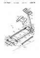
- FIG. 1is a perspective view of the treadmill of the instant invention
- FIG. 2is a perspective view of the right roller bracket for use with the treadmill of FIG. 1;
- FIG. 3is a rear view of the right roller bracket of FIG. 2 with a tail roller spaced therefrom;
- FIG. 4is a side view of the right roller bracket shown in FIGS. 2 and 3;
- FIG. 5shows a right roller bracket and the rear end of the right extension in cross-section
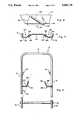
- FIG. 6is a simplified top view of a "U"-shaped frame of the instant invention.
- FIG. 7is a simplified cross-sectional view of the "U"-shaped member of FIG. 6.
- FIG. 8is a partial view of the right extension of the "U"-shaped frame of FIG. 6.
- the treadmill of FIG. 1is generally denominated by the number 10. It has a frame 12 which includes a left extension 13 and a right extension 14. The left and right extensions are each spaced apart from the other and in substantial alignment as illustrated.
- a transverse member 16is interconnected between the left extension 13 and the right extension 14 to form a "U"-shaped frame.
- the left extension 13has a front end 18 and a rear end 20.
- the right extension 14has a front end 22 and a rear end 24.
- a tread base 26is attached to the frame 12 to extend between the left extension 13 and the right extension 14 to support an exercising user thereon.
- a drive roller 28is adhered to and inbetween the left extension 13 and the right extension 14 between the tread base 26 and the transverse member 16. As can be seen, the drive roller 28 is positioned immediately forward of the tread base 26.
- Treadmill 10includes drive means which is secured to the frame 12 and connected to rotate the drive roller 28.
- the drive means illustrated in FIG. 1includes a motor 30 interconnected by a pulley belt 32 to a pulley 34 secured to the drive roller 28.
- Meansmay be provided to vary the speed of the pulley belt 32 by selecting a motor 30 which is a variable speed DC motor or by providing structure to mechanically vary the speed of the pulley belt 32.
- the treadmill 10 of FIG. 1also includes an upstanding post 36 with a handle 38 and console 40 connected thereto.
- the treadmill 10also includes forward wheel structure 42 which is interconnected to a cylinder 44.
- the cylinder 44is connected to a bracket 46.
- the cylinder 44is operable by a lever in the console 40 to urge the wheel structure 42 toward and away from the frame 12 to in turn adjust the angle of inclination of the treadmill 10. As known, by adjusting the angle of inclination, the user may adjust the degree of difficulty of the exercises being performed on the treadmill 10.
- a housing 48is shown in an exploded relationship with respect to the frame 12. More particularly, the housing 48 is configured to be positioned over the motor 30, cylinder 44 and the associated structure positioned forward of the tread base 26 to prevent accidental contact with moving parts and to minimize the number of surfaces and apertures into which a user might step or slip during use.
- the treadmill 10 of FIG. 1has a left roller bracket or end cap 50 and right roller bracket or end cap 52 which are secured to their respective left extension 13 and right extension 14 proximate the rear ends 20 and 24, respectively.
- a tail roller 54is adapted to and between the left roller bracket 50 and the right roller bracket 52 in transverse alignment with the drive roller 28. To be in transverse alignment, the axis 56 of the drive roller 28 is substantially parallel to the axis 58 of the tail roller 54.
- the tail roller 54spaces the left extension 13 from the right extension 14 and secures the left extension to the right extension 14. That is, the tail roller 54 along with the left roller bracket 50 and right roller bracket 52 also act as a transverse member to form the frame.
- the treadmill 10also includes an endless belt 60 which is trained about the drive roller 28 and the tail roller 54 over the top of the tread base 26.
- the usermay walk, jog or run on the endless belt 60 and thereby exercise with the weight of the user being supported by the tread base 26.
- the endless belt 60has an upper stretch 62 which is positioned on top of the tread base 26 and a lower stretch 64 which extends between the drive roller 28 and tail roller 54 under tread base 26.
- a rear foot 66may be provided proximate the rear end 20 of the left extension 13 and the rear end 24 of the right extension 14 to support the frame 12 upon a surface.
- a support foot 68may be bolted to or unitarily formed to be part of the right roller bracket 52 and a similar foot bolted to or formed to be part of the left roller bracket 50 to support the frame 12 and in turn the treadmill 10 on a support surface selected by the user.
- the right roller bracket 52is shown in perspective to have a top surface 70 and a rear surface 72.
- the right roller bracket 52has a right, journal housing 74 which is oriented toward the left roller bracket 50 when secured to the right extension 14.
- the left roller bracket 50has a similar roller bracket housing 76 which is oriented toward the right roller bracket 52 when the left roller bracket 50 is mated to the left extension 13.
- the tail roller 54is adapted to and between the left journal housing and the right journal housing 74. Both the left and the right roller brackets 50 and 52 include adjustment means to adjust the transverse alignment of the tail roller 54 with respect to the drive roller 28.
- the right roller bracket 52 and more particularly the right journal housing 74includes a right shaft slot 76.
- the tail roller 54includes a right shaft 78 which extends outwardly therefrom and which is sized to snugly fit within the slot 76.
- the slot 76is formed by an upper slot member 78 and a lower slot member 80 and is sized in length 82 to provide sufficient distance to facilitate assembly of the treadmill 10 and to provide for adjustment of the tail roller 54, as more fully discussed hereinafter.
- the right journal housinghas an recess 82 which is formed therein substantially in alignment with the slot 76.
- a bolt 84is positioned through the bolt aperture 86 in the recess 82 to connect with the right shaft 78.
- the right shaft 78has an aperture 88 formed therein with threads to threadedly receive the bolt 84.
- the shaft 78may be moved along the length 81 of the slot 76 either toward or away from the rear end 24 of the right extension 14 by operation of the bolt 84.
- the boltis shown with a slot 90 to receive a screw driver.
- the bolt 90may also be configured to receive an allen wrench or any other mechanical device for operating a bolt.
- the right end cap 52has an outside member 92 which together with a base member 94 and internal structural members 96 and 98 form a rectilinear cavity 100 as best seen in FIG. 3.
- a rectilinear cavity 100Within the rectilinear cavity 100 are a plurality of friction beads 102, 104, 106, 108, 110, 112, 114, and 116.
- the cavity 100is sized with the friction beads 102 through 116 to snugly receive the rear end 24 of the right extension 14.
- the friction beads 102 through 116provide for a snug frictional mating and constitute a right connector for connecting the right roller bracket 52 to the rear end 24 of the right extension 14.
- the right connectormay also include a screw 118 to fasten the right roller bracket 52 to the rear end 24 of the right extension 14.
- the left roller bracket 50is similarly configured to have a left connector.
- a left safety step 120is secured to the left extension 13 to extend substantially along the length of the left extension 13 as best seen in FIG. 1.
- a similar safety step 122is positionable on the right extension 14 but is here shown spaced therefrom for clarity of illustration.
- the right safety step 122is shown secured to the right extension 14 with the tread base 26 connected thereinbetween. It can be seen that the right roller bracket and the interior upper surface 98 are spaced apart a preselected distance 124 so that the surface 70 of the right roller bracket 52 is substantially in alignment with the right safety step 122 when the right roller bracket 52 is mated with the end 24 of the right extension 14. In such a fashion, a relatively secure, smooth fit can be effected along with a smooth exterior surface.
- the usermay stand with one foot on the safety step 120 and one foot on the safety step 122 straddling the upper stretch 62 of the endless belt 60. The user may then operate the belt and cause it to move and step onto the endless belt 60 from the safety steps 120 and 122 or from the endless moving belt 60 onto the safety steps 120 and 122 as circumstances require.
- the slot 76is formed of an upper member 78 and a lower member 80.
- the upper member 78is integrally formed with a vertical extension 126.
- the lower member 80is connected to vertical member 128 which in turn is connected to horizontal member 129 and upright member 127.
- the members 126, 127, 128 and 129together provide rigidity by interconnection to the upper surface 70 and to the lower surface 130 of the right roller bracket 52.
- FIGS. 2 through 5illustrate the right roller bracket 52 as shown in FIG. 1.
- the left roller bracket 50 of FIG. 1is substantially identical to the right roller brackets 52 illustrated and described with respect to FIGS. 2 through 5 except that it is configured to be left handed or the mirror image of the right roller bracket 52.
- both the left roller bracket 50 and the right roller bracket 52are shown with a left journal housing 76 and a right journal housing 74 that have an adjustment means and more particularly a adjustment member such as a bolt 84 for adjusting the transverse alignment of the tail roller 54 with respect to the drive roller 28.
- the bolt 132 associated with the left roller bracket 50is operable in the same manner as the bolt 84 associated with the right roller bracket 52.
- an adjustment meansmay be provided only for one of the two roller brackets 50 and 52.
- the roller bracket which does not have an adjustment meansmay be formed to have a simple journal bearing 134 to receive the shaft of the tail roller 54 and to retain the shaft in position with in the selected roller bracket.
- the tail roller 54has a right shaft 78 extending outwardly therefrom.
- the tail roller 54has a pulley member 136 rotatably secured about the shaft 78.
- the right shaft 78extends into and preferably through the pulley structure 136 to extend outwardly from the pulley structure on the left end to form a left shaft similar to the right shaft 78.
- the left shaft as well as the right shaft 78are inserted into their respective left and right shaft slots such as the right shaft slot 76.
- the respective boltssuch as bolts 84 and 132 are threadedly interconnected with the aperture 88 on the right side and a similar aperture on the left shaft (not shown).
- the tail roller 54and more particularly the pulley 136, is positioned between the upper stretch 62 and the lower stretch 64 (FIG. 1).
- the associated brackets 50 and 52are positioned to mate with the rear end 24 of the right extension 14 and the rear end 20 of the left extension 13.
- the endless belt 60urges the pulley 136 towards 138 the extensions 13 and 14.
- the bolts 84 and 132are operated to draw the tail roller 54 outwardly 140 away form the rear end 20 and 24 to in turn snugly secure the belt 60 over the tread base 26.
- Appropriate operation of the bolts 84 and 132also facilitates alignment and in turn the retention of the belt 60 centrally on the pulley 136. That is, slight transverse misalignment allows the endless belt 60 to walk towards the left or to the right extensions 13 and 14.
- Appropriate adjustment of the bolts 132 and 84may be used to reduce the tendency of the belt to walk along the pulley 136.
- the left extension 13 and the right extension 14are shown interconnected with the transverse member 16 to form a "U"-shaped frame.
- the "U"-shaped frameis integrally formed as a single piece, thereby precluding the need for welding, fitting, cutting and abutting transverse support members.
- the cost of manufactureis substantially reduced because the frame 12 may be formed by taking a single tubular member and bending it to the shape illustrated in FIG. 6.
- journal brackets 150 and 152are shown to receive the drive roller 28.
- Rear foot structure 66is also shown which may be added at the option of the user to provide additional transverse support for the left and right extensions 13 and 14 proximate the rear ends 20 and 24.
- a left belt guide 154 and right belt guide 156are also shown in FIG. 6.
- the endless belt 60 and more particularly the lower stretch 64has a left edge 158 and right edge 160.
- the left guide 154 and the right guide 156are each welded or otherwise secured to the underside of their respective left extension 13 and right extension 14.
- the left guide 154has a transverse member 162 welded to the underside of the left extension 13.
- the transverse member 162extends inwardly toward the right extension 14 and is preferably normal, or substantially normal (e.g., +5°) to the left extension 13.
- the right guide 156has a transverse member 164 which extends inwardly toward the left extension 13.
- the transverse member 164is welded to the underside of the right extension 14 and preferably extends inwardly substantially normal to the right extension 14.
- a left finger 166is secured to the end 167 of the left extension 162.
- a right finger 168is secured to the end 169 of the right transverse extension 164.
- the left finger 166 and the right finger 168are oriented to extend upwardly, forwardly and inwardly as illustrated. More particularly, the left finger 166 is shown extending inwardly at an angle 170 of about 20° with respect to the left extension 13.
- the right finger 168is similarly angled in a forward direction. The angle 170 may vary from about 10° to about 30°.
- the right extension 168is shown angled upwardly in FIG. 7 with respect to the transverse member 164 at an angle 172 which is here shown to be about 66° but may be from about 50° to about 75°.
- the left finger 166is similarly angled upwardly.
- FIG. 8it can be seen that the right guide 156 and more particularly the right finger 168 is angled forwardly with respect to the transverse member 164 or the flat underside surface 174 of the right extension 14 at an angle 176 of about 30°.
- the finger 168may be at an angle from about 20° to about 40°.
- left finger 166 and right finger 168are best positioned inwardly at an angle 170 of about 20°; upwardly at an angle 172 of about 66° and forwardly at an angle 176 of about 30°. Such a position results in reduced noise from the belt 60 as well as reduced wear on the belt 60.
- the edge 158 or the edge 160 of the endless belt 60 and more particularly the lower stretch 64may move along the finger 166 down to the connection between the transverse extensions 162 and 164 and their respective fingers 166 and 168.
- the left connection 178 and the right connection 180are preferably rounded or smooth so that the belt edges 158 and 160 may move smoothly thereabout. It has been found in operation that as a belt edge 162 starts to move downwardly along the fingers 168 or 166, an increased force is urged upon the belt edge 162 by the fingers 166, thereby urging the belt edge 162 back into central alignment on the drive roller 28 and the tail roller 54. In such a configuration the drive roller 28 and the tail roller 54 may be a cylindrical configuration found in some treadmills.
- the treadmill 10 of FIG. 1 with the left roller bracket 50 and right roller bracket 52 and its associated tail roller 54facilitates construction of a treadmill by eliminating the need for one or more transverse cross-members secured between the left extension 13 and the right extension 14.
- a simple frame in the shape of a "U”may be readily formed by bending a single member. The economies of manufacture with the additional benefits of increased strength and lower material cost may be realized.
Landscapes
- Health & Medical Sciences (AREA)
- Cardiology (AREA)
- Vascular Medicine (AREA)
- General Health & Medical Sciences (AREA)
- Physical Education & Sports Medicine (AREA)
- Rehabilitation Tools (AREA)
Abstract
Description
Claims (1)
Priority Applications (2)
| Application Number | Priority Date | Filing Date | Title |
|---|---|---|---|
| US07/479,835US5088729A (en) | 1990-02-14 | 1990-02-14 | Treadmill frame and roller bracket assembly |
| US07/884,609US5279528A (en) | 1990-02-14 | 1992-05-15 | Cushioned deck for treadmill |
Applications Claiming Priority (1)
| Application Number | Priority Date | Filing Date | Title |
|---|---|---|---|
| US07/479,835US5088729A (en) | 1990-02-14 | 1990-02-14 | Treadmill frame and roller bracket assembly |
Related Child Applications (1)
| Application Number | Title | Priority Date | Filing Date |
|---|---|---|---|
| US65951291AContinuation-In-Part | 1990-02-14 | 1991-02-21 |
Publications (1)
| Publication Number | Publication Date |
|---|---|
| US5088729Atrue US5088729A (en) | 1992-02-18 |
Family
ID=23905641
Family Applications (1)
| Application Number | Title | Priority Date | Filing Date |
|---|---|---|---|
| US07/479,835Expired - LifetimeUS5088729A (en) | 1990-02-14 | 1990-02-14 | Treadmill frame and roller bracket assembly |
Country Status (1)
| Country | Link |
|---|---|
| US (1) | US5088729A (en) |
Cited By (92)
| Publication number | Priority date | Publication date | Assignee | Title |
|---|---|---|---|---|
| US5441468A (en)* | 1994-03-04 | 1995-08-15 | Quinton Instrument Company | Resiliently mounted treadmill deck |
| US5529553A (en)* | 1995-02-01 | 1996-06-25 | Icon Health & Fitness, Inc. | Treadmill with belt tensioning adjustment |
| US5542892A (en)* | 1994-08-15 | 1996-08-06 | Unisen, Inc. | Supporting chassis for a treadmill |
| US5964681A (en)* | 1997-06-30 | 1999-10-12 | Stevens; Clive Graham | Treadmill exercise device |
| US5989160A (en)* | 1998-02-12 | 1999-11-23 | Greenmaster Industrial Corp. | Belt guiding device for treadmill |
| USD437900S1 (en) | 1998-08-28 | 2001-02-20 | Dick Eric R | Exercise treadmill |
| US6461278B1 (en)* | 1997-03-24 | 2002-10-08 | Per Arne Troset | Treadmill |
| US20020151413A1 (en)* | 1997-10-28 | 2002-10-17 | Dalebout William T. | Fold-out treadmill |
| US20030060331A1 (en)* | 2001-08-08 | 2003-03-27 | Polk Louis F. | Treadmill |
| US20030125165A1 (en)* | 2001-12-31 | 2003-07-03 | Trevino Richard W. | Treadmill |
| US20030153434A1 (en)* | 1998-09-25 | 2003-08-14 | Dalebout William T. | Treadmill with adjustable cushioning members |
| US6652424B2 (en) | 1998-09-25 | 2003-11-25 | William T. Dalebout | Treadmill with adjustable cushioning members |
| US20040043870A1 (en)* | 2002-04-04 | 2004-03-04 | Clarke Kappel Leroy | Fitness method utilizing moving platforms |
| US6743153B2 (en) | 2001-09-06 | 2004-06-01 | Icon Ip, Inc. | Method and apparatus for treadmill with frameless treadbase |
| US6761667B1 (en) | 2000-02-02 | 2004-07-13 | Icon Ip, Inc. | Hiking exercise apparatus |
| US20040152566A1 (en)* | 2003-01-30 | 2004-08-05 | Chien-Chung Yeh | External plastic structure of a treadmill |
| US20040171465A1 (en)* | 2001-09-28 | 2004-09-02 | Patrick Hald | Treadmill belt safety mechanism |
| US20040214693A1 (en)* | 2003-02-28 | 2004-10-28 | Nautilus, Inc. | Dual deck exercise device |
| US6821230B2 (en) | 1998-09-25 | 2004-11-23 | Icon Ip, Inc. | Treadmill with adjustable cushioning members |
| US20050037898A1 (en)* | 2003-08-11 | 2005-02-17 | Dick Chang | Combination of treadmill and stair climbing machine |
| US6860839B1 (en) | 2003-04-07 | 2005-03-01 | Michael P. Dice | Universal rear safety cover for treadmills |
| US20050148442A1 (en)* | 1996-01-30 | 2005-07-07 | Watterson Scott R. | Reorienting treadmill |
| US20050164839A1 (en)* | 2004-01-09 | 2005-07-28 | Watterson Scott R. | Cushioning treadmill |
| US20050209052A1 (en)* | 2000-02-02 | 2005-09-22 | Ashby Darren C | System and method for selective adjustment of exercise apparatus |
| USD527060S1 (en) | 2004-03-22 | 2006-08-22 | Nautilus, Inc. | Exercise device with treadles |
| US7537549B2 (en) | 2000-02-02 | 2009-05-26 | Icon Ip, Inc. | Incline assembly with cam |
| US20090137367A1 (en)* | 2000-02-02 | 2009-05-28 | Icon Ip, Inc. | Inclining treadmill with magnetic braking system |
| US20100173755A1 (en)* | 2009-01-05 | 2010-07-08 | P Erez De Lazarraga Pablo | Base for a treadmill |
| USRE42698E1 (en) | 2001-07-25 | 2011-09-13 | Nautilus, Inc. | Treadmill having dual treads for stepping exercises |
| US8690735B2 (en) | 1999-07-08 | 2014-04-08 | Icon Health & Fitness, Inc. | Systems for interaction with exercise device |
| US8758201B2 (en) | 1999-07-08 | 2014-06-24 | Icon Health & Fitness, Inc. | Portable physical activity sensing system |
| USD726845S1 (en)* | 2014-03-12 | 2015-04-14 | Precor Incorporated | Side rails of a treadmill |
| US9028368B2 (en) | 1999-07-08 | 2015-05-12 | Icon Health & Fitness, Inc. | Systems, methods, and devices for simulating real world terrain on an exercise device |
| US10188890B2 (en) | 2013-12-26 | 2019-01-29 | Icon Health & Fitness, Inc. | Magnetic resistance mechanism in a cable machine |
| US10220259B2 (en) | 2012-01-05 | 2019-03-05 | Icon Health & Fitness, Inc. | System and method for controlling an exercise device |
| US10226396B2 (en) | 2014-06-20 | 2019-03-12 | Icon Health & Fitness, Inc. | Post workout massage device |
| US10252109B2 (en) | 2016-05-13 | 2019-04-09 | Icon Health & Fitness, Inc. | Weight platform treadmill |
| US10258828B2 (en) | 2015-01-16 | 2019-04-16 | Icon Health & Fitness, Inc. | Controls for an exercise device |
| US10272317B2 (en) | 2016-03-18 | 2019-04-30 | Icon Health & Fitness, Inc. | Lighted pace feature in a treadmill |
| US10279212B2 (en) | 2013-03-14 | 2019-05-07 | Icon Health & Fitness, Inc. | Strength training apparatus with flywheel and related methods |
| US10293211B2 (en) | 2016-03-18 | 2019-05-21 | Icon Health & Fitness, Inc. | Coordinated weight selection |
| US10343017B2 (en) | 2016-11-01 | 2019-07-09 | Icon Health & Fitness, Inc. | Distance sensor for console positioning |
| US10376736B2 (en) | 2016-10-12 | 2019-08-13 | Icon Health & Fitness, Inc. | Cooling an exercise device during a dive motor runway condition |
| US10388183B2 (en) | 2015-02-27 | 2019-08-20 | Icon Health & Fitness, Inc. | Encouraging achievement of health goals |
| US10391361B2 (en) | 2015-02-27 | 2019-08-27 | Icon Health & Fitness, Inc. | Simulating real-world terrain on an exercise device |
| US10426989B2 (en) | 2014-06-09 | 2019-10-01 | Icon Health & Fitness, Inc. | Cable system incorporated into a treadmill |
| US10433612B2 (en) | 2014-03-10 | 2019-10-08 | Icon Health & Fitness, Inc. | Pressure sensor to quantify work |
| US10441844B2 (en) | 2016-07-01 | 2019-10-15 | Icon Health & Fitness, Inc. | Cooling systems and methods for exercise equipment |
| US10471299B2 (en) | 2016-07-01 | 2019-11-12 | Icon Health & Fitness, Inc. | Systems and methods for cooling internal exercise equipment components |
| US10493349B2 (en) | 2016-03-18 | 2019-12-03 | Icon Health & Fitness, Inc. | Display on exercise device |
| EP3374041A4 (en)* | 2015-11-14 | 2019-12-04 | Jordan Frank | RUNNING MAT |
| US10500473B2 (en) | 2016-10-10 | 2019-12-10 | Icon Health & Fitness, Inc. | Console positioning |
| US10543395B2 (en) | 2016-12-05 | 2020-01-28 | Icon Health & Fitness, Inc. | Offsetting treadmill deck weight during operation |
| US10561894B2 (en) | 2016-03-18 | 2020-02-18 | Icon Health & Fitness, Inc. | Treadmill with removable supports |
| US10625137B2 (en) | 2016-03-18 | 2020-04-21 | Icon Health & Fitness, Inc. | Coordinated displays in an exercise device |
| US10661114B2 (en) | 2016-11-01 | 2020-05-26 | Icon Health & Fitness, Inc. | Body weight lift mechanism on treadmill |
| US10671705B2 (en) | 2016-09-28 | 2020-06-02 | Icon Health & Fitness, Inc. | Customizing recipe recommendations |
| US10729965B2 (en) | 2017-12-22 | 2020-08-04 | Icon Health & Fitness, Inc. | Audible belt guide in a treadmill |
| US10786706B2 (en) | 2018-07-13 | 2020-09-29 | Icon Health & Fitness, Inc. | Cycling shoe power sensors |
| US10918905B2 (en) | 2016-10-12 | 2021-02-16 | Icon Health & Fitness, Inc. | Systems and methods for reducing runaway resistance on an exercise device |
| US10940360B2 (en) | 2015-08-26 | 2021-03-09 | Icon Health & Fitness, Inc. | Strength exercise mechanisms |
| US10953305B2 (en) | 2015-08-26 | 2021-03-23 | Icon Health & Fitness, Inc. | Strength exercise mechanisms |
| US11000730B2 (en) | 2018-03-16 | 2021-05-11 | Icon Health & Fitness, Inc. | Elliptical exercise machine |
| US11033777B1 (en) | 2019-02-12 | 2021-06-15 | Icon Health & Fitness, Inc. | Stationary exercise machine |
| US11058914B2 (en) | 2016-07-01 | 2021-07-13 | Icon Health & Fitness, Inc. | Cooling methods for exercise equipment |
| US11058913B2 (en) | 2017-12-22 | 2021-07-13 | Icon Health & Fitness, Inc. | Inclinable exercise machine |
| US11187285B2 (en) | 2017-12-09 | 2021-11-30 | Icon Health & Fitness, Inc. | Systems and methods for selectively rotationally fixing a pedaled drivetrain |
| US20220016474A1 (en)* | 2018-12-07 | 2022-01-20 | Remedy Innovations Ltd | A treadmill exercise apparatus |
| US11244751B2 (en) | 2012-10-19 | 2022-02-08 | Finish Time Holdings, Llc | Method and device for providing a person with training data of an athlete as the athlete is performing a swimming workout |
| US11298577B2 (en) | 2019-02-11 | 2022-04-12 | Ifit Inc. | Cable and power rack exercise machine |
| US11326673B2 (en) | 2018-06-11 | 2022-05-10 | Ifit Inc. | Increased durability linear actuator |
| US11451108B2 (en) | 2017-08-16 | 2022-09-20 | Ifit Inc. | Systems and methods for axial impact resistance in electric motors |
| US11534651B2 (en) | 2019-08-15 | 2022-12-27 | Ifit Inc. | Adjustable dumbbell system |
| US11534654B2 (en) | 2019-01-25 | 2022-12-27 | Ifit Inc. | Systems and methods for an interactive pedaled exercise device |
| US11673036B2 (en) | 2019-11-12 | 2023-06-13 | Ifit Inc. | Exercise storage system |
| US11794070B2 (en) | 2019-05-23 | 2023-10-24 | Ifit Inc. | Systems and methods for cooling an exercise device |
| US11850497B2 (en) | 2019-10-11 | 2023-12-26 | Ifit Inc. | Modular exercise device |
| US11878199B2 (en) | 2021-02-16 | 2024-01-23 | Ifit Inc. | Safety mechanism for an adjustable dumbbell |
| US11931621B2 (en) | 2020-03-18 | 2024-03-19 | Ifit Inc. | Systems and methods for treadmill drift avoidance |
| US11951377B2 (en) | 2020-03-24 | 2024-04-09 | Ifit Inc. | Leaderboard with irregularity flags in an exercise machine system |
| US11986697B1 (en)* | 2022-11-04 | 2024-05-21 | Peloton Interactive, Inc. | Mechanical assemblies for a treadmill |
| US12029961B2 (en) | 2020-03-24 | 2024-07-09 | Ifit Inc. | Flagging irregularities in user performance in an exercise machine system |
| US12029935B2 (en) | 2021-08-19 | 2024-07-09 | Ifit Inc. | Adjustment mechanism for an adjustable kettlebell |
| US12176009B2 (en) | 2021-12-30 | 2024-12-24 | Ifit Inc. | Systems and methods for synchronizing workout equipment with video files |
| US12219201B2 (en) | 2021-08-05 | 2025-02-04 | Ifit Inc. | Synchronizing video workout programs across multiple devices |
| US12263371B2 (en) | 2021-04-27 | 2025-04-01 | Ifit Inc. | Devices, systems, and methods for rotating a tread belt in two directions |
| US12280294B2 (en) | 2021-10-15 | 2025-04-22 | Ifit Inc. | Magnetic clutch for a pedaled drivetrain |
| US12350547B2 (en) | 2022-02-28 | 2025-07-08 | Ifit Inc. | Devices, systems, and methods for moving a movable step through a transition zone |
| US12350573B2 (en) | 2021-04-27 | 2025-07-08 | Ifit Inc. | Systems and methods for cross-training on exercise devices |
| US12409375B2 (en) | 2022-03-18 | 2025-09-09 | Ifit Inc. | Systems and methods for haptic simulation in incline exercise devices |
| US12433815B2 (en) | 2020-10-02 | 2025-10-07 | Ifit Inc. | Massage roller with pressure sensors |
| US12440723B2 (en)* | 2024-05-20 | 2025-10-14 | Peloton Interactive, Inc. | Mechanical assemblies for a treadmill |
Citations (10)
| Publication number | Priority date | Publication date | Assignee | Title |
|---|---|---|---|---|
| US3731917A (en)* | 1971-02-25 | 1973-05-08 | Townsend Engineering Co | Treadmill exercising device |
| US4077626A (en)* | 1974-11-13 | 1978-03-07 | Joe Westley Newman | Exercising machine |
| US4374587A (en)* | 1980-08-05 | 1983-02-22 | Ralph Ogden | Exercise treadmill |
| US4423864A (en)* | 1981-10-13 | 1984-01-03 | Wiik Sven E | Angularly adjustable ski deck |
| US4591147A (en)* | 1984-09-06 | 1986-05-27 | Precor Incorporated | System for elevating an exercise treadmill |
| EP0196877A2 (en)* | 1985-03-26 | 1986-10-08 | Barry Laurence Hayes | Shock absorbent moving platform |
| US4616822A (en)* | 1984-08-01 | 1986-10-14 | Trulaske James A | Exercise treadmill |
| US4729558A (en)* | 1985-10-11 | 1988-03-08 | Kuo Hai P | Running exerciser |
| US4736944A (en)* | 1986-10-09 | 1988-04-12 | M & R Industries, Inc. | Exercise rowing machine frame structure |
| US4886266A (en)* | 1988-05-23 | 1989-12-12 | True Fitness Technology, Inc. | Exercise treadmill |
- 1990
- 1990-02-14USUS07/479,835patent/US5088729A/ennot_activeExpired - Lifetime
Patent Citations (10)
| Publication number | Priority date | Publication date | Assignee | Title |
|---|---|---|---|---|
| US3731917A (en)* | 1971-02-25 | 1973-05-08 | Townsend Engineering Co | Treadmill exercising device |
| US4077626A (en)* | 1974-11-13 | 1978-03-07 | Joe Westley Newman | Exercising machine |
| US4374587A (en)* | 1980-08-05 | 1983-02-22 | Ralph Ogden | Exercise treadmill |
| US4423864A (en)* | 1981-10-13 | 1984-01-03 | Wiik Sven E | Angularly adjustable ski deck |
| US4616822A (en)* | 1984-08-01 | 1986-10-14 | Trulaske James A | Exercise treadmill |
| US4591147A (en)* | 1984-09-06 | 1986-05-27 | Precor Incorporated | System for elevating an exercise treadmill |
| EP0196877A2 (en)* | 1985-03-26 | 1986-10-08 | Barry Laurence Hayes | Shock absorbent moving platform |
| US4729558A (en)* | 1985-10-11 | 1988-03-08 | Kuo Hai P | Running exerciser |
| US4736944A (en)* | 1986-10-09 | 1988-04-12 | M & R Industries, Inc. | Exercise rowing machine frame structure |
| US4886266A (en)* | 1988-05-23 | 1989-12-12 | True Fitness Technology, Inc. | Exercise treadmill |
Cited By (150)
| Publication number | Priority date | Publication date | Assignee | Title |
|---|---|---|---|---|
| US5441468A (en)* | 1994-03-04 | 1995-08-15 | Quinton Instrument Company | Resiliently mounted treadmill deck |
| US5542892A (en)* | 1994-08-15 | 1996-08-06 | Unisen, Inc. | Supporting chassis for a treadmill |
| US5529553A (en)* | 1995-02-01 | 1996-06-25 | Icon Health & Fitness, Inc. | Treadmill with belt tensioning adjustment |
| US6974404B1 (en) | 1996-01-30 | 2005-12-13 | Icon Ip, Inc. | Reorienting treadmill |
| US20050148442A1 (en)* | 1996-01-30 | 2005-07-07 | Watterson Scott R. | Reorienting treadmill |
| US20050148443A1 (en)* | 1996-01-30 | 2005-07-07 | Watterson Scott R. | Reorienting treadmill |
| US7540828B2 (en) | 1996-01-30 | 2009-06-02 | Icon Ip, Inc. | Reorienting treadmill |
| US6461278B1 (en)* | 1997-03-24 | 2002-10-08 | Per Arne Troset | Treadmill |
| US5964681A (en)* | 1997-06-30 | 1999-10-12 | Stevens; Clive Graham | Treadmill exercise device |
| US20020151413A1 (en)* | 1997-10-28 | 2002-10-17 | Dalebout William T. | Fold-out treadmill |
| US7192388B2 (en) | 1997-10-28 | 2007-03-20 | Icon Health & Fitness, Inc. | Fold-out treadmill |
| US5989160A (en)* | 1998-02-12 | 1999-11-23 | Greenmaster Industrial Corp. | Belt guiding device for treadmill |
| USD437900S1 (en) | 1998-08-28 | 2001-02-20 | Dick Eric R | Exercise treadmill |
| US20030153434A1 (en)* | 1998-09-25 | 2003-08-14 | Dalebout William T. | Treadmill with adjustable cushioning members |
| US7563203B2 (en) | 1998-09-25 | 2009-07-21 | Icon Ip, Inc. | Treadmill with adjustable cushioning members |
| US6652424B2 (en) | 1998-09-25 | 2003-11-25 | William T. Dalebout | Treadmill with adjustable cushioning members |
| US6821230B2 (en) | 1998-09-25 | 2004-11-23 | Icon Ip, Inc. | Treadmill with adjustable cushioning members |
| US8690735B2 (en) | 1999-07-08 | 2014-04-08 | Icon Health & Fitness, Inc. | Systems for interaction with exercise device |
| US8758201B2 (en) | 1999-07-08 | 2014-06-24 | Icon Health & Fitness, Inc. | Portable physical activity sensing system |
| US8784270B2 (en) | 1999-07-08 | 2014-07-22 | Icon Ip, Inc. | Portable physical activity sensing system |
| US9028368B2 (en) | 1999-07-08 | 2015-05-12 | Icon Health & Fitness, Inc. | Systems, methods, and devices for simulating real world terrain on an exercise device |
| US20050209052A1 (en)* | 2000-02-02 | 2005-09-22 | Ashby Darren C | System and method for selective adjustment of exercise apparatus |
| US9623281B2 (en) | 2000-02-02 | 2017-04-18 | Icon Health & Fitness, Inc. | Exercise device with braking system |
| US8876668B2 (en) | 2000-02-02 | 2014-11-04 | Icon Ip, Inc. | Exercise device with magnetic braking system |
| US6761667B1 (en) | 2000-02-02 | 2004-07-13 | Icon Ip, Inc. | Hiking exercise apparatus |
| US20110152039A1 (en)* | 2000-02-02 | 2011-06-23 | Icon Ip, Inc. | Exercise device with magnetic braking system |
| US7862483B2 (en) | 2000-02-02 | 2011-01-04 | Icon Ip, Inc. | Inclining treadmill with magnetic braking system |
| US7645212B2 (en) | 2000-02-02 | 2010-01-12 | Icon Ip, Inc. | System and method for selective adjustment of exercise apparatus |
| US20090137367A1 (en)* | 2000-02-02 | 2009-05-28 | Icon Ip, Inc. | Inclining treadmill with magnetic braking system |
| US7537549B2 (en) | 2000-02-02 | 2009-05-26 | Icon Ip, Inc. | Incline assembly with cam |
| USRE42698E1 (en) | 2001-07-25 | 2011-09-13 | Nautilus, Inc. | Treadmill having dual treads for stepping exercises |
| US7357758B2 (en)* | 2001-08-08 | 2008-04-15 | Polk Iii Louis F | Treadmill |
| US20030060331A1 (en)* | 2001-08-08 | 2003-03-27 | Polk Louis F. | Treadmill |
| US7377882B2 (en) | 2001-09-06 | 2008-05-27 | Icon Ip, Inc. | Method and apparatus for treadmill with frameless treadbase |
| US20040176217A1 (en)* | 2001-09-06 | 2004-09-09 | Watterson Scott R. | Method and apparatus for treadmill with frameless treadbase |
| US6743153B2 (en) | 2001-09-06 | 2004-06-01 | Icon Ip, Inc. | Method and apparatus for treadmill with frameless treadbase |
| US7052442B2 (en) | 2001-09-06 | 2006-05-30 | Icon Ip, Inc. | Method and apparatus for treadmill with frameless treadbase |
| US20060217236A1 (en)* | 2001-09-06 | 2006-09-28 | Watterson Scott R | Method and apparatus for treadmill with frameless treadbase |
| US20040171465A1 (en)* | 2001-09-28 | 2004-09-02 | Patrick Hald | Treadmill belt safety mechanism |
| US7544153B2 (en) | 2001-12-31 | 2009-06-09 | Nautilus, Inc. | Treadmill |
| US20070054780A1 (en)* | 2001-12-31 | 2007-03-08 | Hebb Industries, Inc. | Treadmill |
| US20030125165A1 (en)* | 2001-12-31 | 2003-07-03 | Trevino Richard W. | Treadmill |
| US7455626B2 (en) | 2001-12-31 | 2008-11-25 | Nautilus, Inc. | Treadmill |
| US7258651B2 (en)* | 2002-04-04 | 2007-08-21 | Kappel Leroy Clarke | Fitness method utilizing moving platforms |
| US20040043870A1 (en)* | 2002-04-04 | 2004-03-04 | Clarke Kappel Leroy | Fitness method utilizing moving platforms |
| US20040152566A1 (en)* | 2003-01-30 | 2004-08-05 | Chien-Chung Yeh | External plastic structure of a treadmill |
| US20040214693A1 (en)* | 2003-02-28 | 2004-10-28 | Nautilus, Inc. | Dual deck exercise device |
| US6860839B1 (en) | 2003-04-07 | 2005-03-01 | Michael P. Dice | Universal rear safety cover for treadmills |
| US7097593B2 (en) | 2003-08-11 | 2006-08-29 | Nautilus, Inc. | Combination of treadmill and stair climbing machine |
| US20050037898A1 (en)* | 2003-08-11 | 2005-02-17 | Dick Chang | Combination of treadmill and stair climbing machine |
| US20050164839A1 (en)* | 2004-01-09 | 2005-07-28 | Watterson Scott R. | Cushioning treadmill |
| USD527060S1 (en) | 2004-03-22 | 2006-08-22 | Nautilus, Inc. | Exercise device with treadles |
| US7828699B2 (en)* | 2009-01-05 | 2010-11-09 | P Erez De Lazarraga Pablo | Base for a treadmill |
| US20100173755A1 (en)* | 2009-01-05 | 2010-07-08 | P Erez De Lazarraga Pablo | Base for a treadmill |
| US10220259B2 (en) | 2012-01-05 | 2019-03-05 | Icon Health & Fitness, Inc. | System and method for controlling an exercise device |
| US11923066B2 (en) | 2012-10-19 | 2024-03-05 | Finish Time Holdings, Llc | System and method for providing a trainer with live training data of an individual as the individual is performing a training workout |
| US11322240B2 (en) | 2012-10-19 | 2022-05-03 | Finish Time Holdings, Llc | Method and device for providing a person with training data of an athlete as the athlete is performing a running workout |
| US11244751B2 (en) | 2012-10-19 | 2022-02-08 | Finish Time Holdings, Llc | Method and device for providing a person with training data of an athlete as the athlete is performing a swimming workout |
| US11810656B2 (en) | 2012-10-19 | 2023-11-07 | Finish Time Holdings, Llc | System for providing a coach with live training data of an athlete as the athlete is training |
| US12340891B2 (en) | 2012-10-19 | 2025-06-24 | Finish Time Network LLC | System and method for providing a trainer with live training data of an individual as the individual is performing a training workout |
| US10279212B2 (en) | 2013-03-14 | 2019-05-07 | Icon Health & Fitness, Inc. | Strength training apparatus with flywheel and related methods |
| US11338169B2 (en) | 2013-03-14 | 2022-05-24 | IFIT, Inc. | Strength training apparatus |
| US11878206B2 (en) | 2013-03-14 | 2024-01-23 | Ifit Inc. | Strength training apparatus |
| US10953268B1 (en) | 2013-03-14 | 2021-03-23 | Icon Health & Fitness, Inc. | Strength training apparatus |
| US10709925B2 (en) | 2013-03-14 | 2020-07-14 | Icon Health & Fitness, Inc. | Strength training apparatus |
| US10188890B2 (en) | 2013-12-26 | 2019-01-29 | Icon Health & Fitness, Inc. | Magnetic resistance mechanism in a cable machine |
| US10967214B1 (en) | 2013-12-26 | 2021-04-06 | Icon Health & Fitness, Inc. | Cable exercise machine |
| US10758767B2 (en) | 2013-12-26 | 2020-09-01 | Icon Health & Fitness, Inc. | Resistance mechanism in a cable exercise machine |
| US11700905B2 (en) | 2014-03-10 | 2023-07-18 | Ifit Inc. | Pressure sensor to quantify work |
| US10433612B2 (en) | 2014-03-10 | 2019-10-08 | Icon Health & Fitness, Inc. | Pressure sensor to quantify work |
| USD726845S1 (en)* | 2014-03-12 | 2015-04-14 | Precor Incorporated | Side rails of a treadmill |
| US10426989B2 (en) | 2014-06-09 | 2019-10-01 | Icon Health & Fitness, Inc. | Cable system incorporated into a treadmill |
| US10226396B2 (en) | 2014-06-20 | 2019-03-12 | Icon Health & Fitness, Inc. | Post workout massage device |
| US10258828B2 (en) | 2015-01-16 | 2019-04-16 | Icon Health & Fitness, Inc. | Controls for an exercise device |
| US10388183B2 (en) | 2015-02-27 | 2019-08-20 | Icon Health & Fitness, Inc. | Encouraging achievement of health goals |
| US10391361B2 (en) | 2015-02-27 | 2019-08-27 | Icon Health & Fitness, Inc. | Simulating real-world terrain on an exercise device |
| US10940360B2 (en) | 2015-08-26 | 2021-03-09 | Icon Health & Fitness, Inc. | Strength exercise mechanisms |
| US10953305B2 (en) | 2015-08-26 | 2021-03-23 | Icon Health & Fitness, Inc. | Strength exercise mechanisms |
| US12157031B2 (en) | 2015-11-14 | 2024-12-03 | Runway Treadmill, Llc | Exercise treadmill |
| US11951351B2 (en) | 2015-11-14 | 2024-04-09 | Runway Treadmill, Llc | Exercise treadmill |
| EP3374041A4 (en)* | 2015-11-14 | 2019-12-04 | Jordan Frank | RUNNING MAT |
| US11000728B2 (en) | 2015-11-14 | 2021-05-11 | Jordan Frank | Exercise treadmill |
| US11794075B2 (en) | 2016-03-18 | 2023-10-24 | Ifit Inc. | Stationary exercise machine configured to execute a programmed workout with aerobic portions and lifting portions |
| US11013960B2 (en) | 2016-03-18 | 2021-05-25 | Icon Health & Fitness, Inc. | Exercise system including a stationary bicycle and a free weight cradle |
| US10272317B2 (en) | 2016-03-18 | 2019-04-30 | Icon Health & Fitness, Inc. | Lighted pace feature in a treadmill |
| US11565148B2 (en) | 2016-03-18 | 2023-01-31 | Ifit Inc. | Treadmill with a scale mechanism in a motor cover |
| US12029944B2 (en) | 2016-03-18 | 2024-07-09 | Ifit Inc. | Stationary exercise machine configured to execute a programmed workout with aerobic portions and lifting portions |
| US10625137B2 (en) | 2016-03-18 | 2020-04-21 | Icon Health & Fitness, Inc. | Coordinated displays in an exercise device |
| US10293211B2 (en) | 2016-03-18 | 2019-05-21 | Icon Health & Fitness, Inc. | Coordinated weight selection |
| US10493349B2 (en) | 2016-03-18 | 2019-12-03 | Icon Health & Fitness, Inc. | Display on exercise device |
| US10561894B2 (en) | 2016-03-18 | 2020-02-18 | Icon Health & Fitness, Inc. | Treadmill with removable supports |
| US12023549B2 (en) | 2016-03-18 | 2024-07-02 | Ifit Inc. | Stationary exercise machine configured to execute a programmed workout with aerobic portions and lifting portions |
| US12029943B2 (en) | 2016-03-18 | 2024-07-09 | Ifit Inc. | Stationary exercise machine configured to execute a programmed workout with aerobic portions and lifting portions |
| US11779812B2 (en) | 2016-05-13 | 2023-10-10 | Ifit Inc. | Treadmill configured to automatically determine user exercise movement |
| US10994173B2 (en) | 2016-05-13 | 2021-05-04 | Icon Health & Fitness, Inc. | Weight platform treadmill |
| US10252109B2 (en) | 2016-05-13 | 2019-04-09 | Icon Health & Fitness, Inc. | Weight platform treadmill |
| US11058914B2 (en) | 2016-07-01 | 2021-07-13 | Icon Health & Fitness, Inc. | Cooling methods for exercise equipment |
| US10471299B2 (en) | 2016-07-01 | 2019-11-12 | Icon Health & Fitness, Inc. | Systems and methods for cooling internal exercise equipment components |
| US10441844B2 (en) | 2016-07-01 | 2019-10-15 | Icon Health & Fitness, Inc. | Cooling systems and methods for exercise equipment |
| US10671705B2 (en) | 2016-09-28 | 2020-06-02 | Icon Health & Fitness, Inc. | Customizing recipe recommendations |
| US10500473B2 (en) | 2016-10-10 | 2019-12-10 | Icon Health & Fitness, Inc. | Console positioning |
| US10376736B2 (en) | 2016-10-12 | 2019-08-13 | Icon Health & Fitness, Inc. | Cooling an exercise device during a dive motor runway condition |
| US10918905B2 (en) | 2016-10-12 | 2021-02-16 | Icon Health & Fitness, Inc. | Systems and methods for reducing runaway resistance on an exercise device |
| US10661114B2 (en) | 2016-11-01 | 2020-05-26 | Icon Health & Fitness, Inc. | Body weight lift mechanism on treadmill |
| US10343017B2 (en) | 2016-11-01 | 2019-07-09 | Icon Health & Fitness, Inc. | Distance sensor for console positioning |
| US10543395B2 (en) | 2016-12-05 | 2020-01-28 | Icon Health & Fitness, Inc. | Offsetting treadmill deck weight during operation |
| US11451108B2 (en) | 2017-08-16 | 2022-09-20 | Ifit Inc. | Systems and methods for axial impact resistance in electric motors |
| US11187285B2 (en) | 2017-12-09 | 2021-11-30 | Icon Health & Fitness, Inc. | Systems and methods for selectively rotationally fixing a pedaled drivetrain |
| US12270441B2 (en) | 2017-12-09 | 2025-04-08 | Ifit Inc. | Systems and methods for selectively rotationally fixing a pedaled drivetrain |
| US11708874B2 (en) | 2017-12-09 | 2023-07-25 | Ifit Inc. | Systems and methods for selectively rotationally fixing a pedaled drivetrain |
| US11680611B2 (en) | 2017-12-09 | 2023-06-20 | Ifit Inc. | Systems and methods for selectively rotationally fixing a pedaled drivetrain |
| US10729965B2 (en) | 2017-12-22 | 2020-08-04 | Icon Health & Fitness, Inc. | Audible belt guide in a treadmill |
| US11058913B2 (en) | 2017-12-22 | 2021-07-13 | Icon Health & Fitness, Inc. | Inclinable exercise machine |
| US11596830B2 (en) | 2018-03-16 | 2023-03-07 | Ifit Inc. | Elliptical exercise machine |
| US11000730B2 (en) | 2018-03-16 | 2021-05-11 | Icon Health & Fitness, Inc. | Elliptical exercise machine |
| US11326673B2 (en) | 2018-06-11 | 2022-05-10 | Ifit Inc. | Increased durability linear actuator |
| US12005315B2 (en) | 2018-07-13 | 2024-06-11 | Ifit Inc. | Cycling shoe power sensors |
| US10786706B2 (en) | 2018-07-13 | 2020-09-29 | Icon Health & Fitness, Inc. | Cycling shoe power sensors |
| US11918846B2 (en)* | 2018-12-07 | 2024-03-05 | Remedy Innovations Ltd | Treadmill exercise apparatus |
| US20220016474A1 (en)* | 2018-12-07 | 2022-01-20 | Remedy Innovations Ltd | A treadmill exercise apparatus |
| US11534654B2 (en) | 2019-01-25 | 2022-12-27 | Ifit Inc. | Systems and methods for an interactive pedaled exercise device |
| US11298577B2 (en) | 2019-02-11 | 2022-04-12 | Ifit Inc. | Cable and power rack exercise machine |
| US11642564B2 (en) | 2019-02-11 | 2023-05-09 | Ifit Inc. | Exercise machine |
| US11452903B2 (en) | 2019-02-11 | 2022-09-27 | Ifit Inc. | Exercise machine |
| US11033777B1 (en) | 2019-02-12 | 2021-06-15 | Icon Health & Fitness, Inc. | Stationary exercise machine |
| US11426633B2 (en) | 2019-02-12 | 2022-08-30 | Ifit Inc. | Controlling an exercise machine using a video workout program |
| US11951358B2 (en) | 2019-02-12 | 2024-04-09 | Ifit Inc. | Encoding exercise machine control commands in subtitle streams |
| US11058918B1 (en) | 2019-02-12 | 2021-07-13 | Icon Health & Fitness, Inc. | Producing a workout video to control a stationary exercise machine |
| US11794070B2 (en) | 2019-05-23 | 2023-10-24 | Ifit Inc. | Systems and methods for cooling an exercise device |
| US11534651B2 (en) | 2019-08-15 | 2022-12-27 | Ifit Inc. | Adjustable dumbbell system |
| US11850497B2 (en) | 2019-10-11 | 2023-12-26 | Ifit Inc. | Modular exercise device |
| US12296247B2 (en) | 2019-10-11 | 2025-05-13 | Ifit Inc. | Modular exercise device |
| US11673036B2 (en) | 2019-11-12 | 2023-06-13 | Ifit Inc. | Exercise storage system |
| US11931621B2 (en) | 2020-03-18 | 2024-03-19 | Ifit Inc. | Systems and methods for treadmill drift avoidance |
| US11951377B2 (en) | 2020-03-24 | 2024-04-09 | Ifit Inc. | Leaderboard with irregularity flags in an exercise machine system |
| US12029961B2 (en) | 2020-03-24 | 2024-07-09 | Ifit Inc. | Flagging irregularities in user performance in an exercise machine system |
| US12433815B2 (en) | 2020-10-02 | 2025-10-07 | Ifit Inc. | Massage roller with pressure sensors |
| US11878199B2 (en) | 2021-02-16 | 2024-01-23 | Ifit Inc. | Safety mechanism for an adjustable dumbbell |
| US12239872B2 (en) | 2021-02-16 | 2025-03-04 | Ifit Inc. | Safety mechanism for an adjustable dumbbell |
| US12263371B2 (en) | 2021-04-27 | 2025-04-01 | Ifit Inc. | Devices, systems, and methods for rotating a tread belt in two directions |
| US12350573B2 (en) | 2021-04-27 | 2025-07-08 | Ifit Inc. | Systems and methods for cross-training on exercise devices |
| US12219201B2 (en) | 2021-08-05 | 2025-02-04 | Ifit Inc. | Synchronizing video workout programs across multiple devices |
| US12029935B2 (en) | 2021-08-19 | 2024-07-09 | Ifit Inc. | Adjustment mechanism for an adjustable kettlebell |
| US12280294B2 (en) | 2021-10-15 | 2025-04-22 | Ifit Inc. | Magnetic clutch for a pedaled drivetrain |
| US12176009B2 (en) | 2021-12-30 | 2024-12-24 | Ifit Inc. | Systems and methods for synchronizing workout equipment with video files |
| US12350547B2 (en) | 2022-02-28 | 2025-07-08 | Ifit Inc. | Devices, systems, and methods for moving a movable step through a transition zone |
| US12409375B2 (en) | 2022-03-18 | 2025-09-09 | Ifit Inc. | Systems and methods for haptic simulation in incline exercise devices |
| US11986697B1 (en)* | 2022-11-04 | 2024-05-21 | Peloton Interactive, Inc. | Mechanical assemblies for a treadmill |
| US20240299801A1 (en)* | 2022-11-04 | 2024-09-12 | Peloton Interactive, Inc. | Mechanical Assemblies for a Treadmill |
| US12440723B2 (en)* | 2024-05-20 | 2025-10-14 | Peloton Interactive, Inc. | Mechanical assemblies for a treadmill |
Similar Documents
| Publication | Publication Date | Title |
|---|---|---|
| US5088729A (en) | Treadmill frame and roller bracket assembly | |
| US5529553A (en) | Treadmill with belt tensioning adjustment | |
| US6135925A (en) | Running exerciser | |
| US4776582A (en) | Exercise treadmill with adjustable slope | |
| US7022051B2 (en) | Running machine | |
| US20230110565A1 (en) | Exercise Bike | |
| US7731636B2 (en) | Resistance system for an exercise device | |
| US5779598A (en) | Pedal-type exerciser | |
| US5938551A (en) | Variable tension pulley system | |
| EP3137174B1 (en) | Stair climbing apparatus and method | |
| US5058881A (en) | Exercise machine height adjustment foot | |
| EP1595521B1 (en) | Massage device | |
| US7722507B2 (en) | Inclination controlling device of treadmill | |
| US5741205A (en) | Exercise apparatus pedal mechanism | |
| US5000442A (en) | Cross country ski exerciser | |
| US6551218B2 (en) | Deep stride exercise machine | |
| US6254515B1 (en) | Apparatus for stabilizing a treadmill | |
| US20070225126A1 (en) | Actuator for controlling inclination of treadmill and inclination control device of treadmill | |
| US6378882B1 (en) | Human-powered exercise cycle | |
| US20250065185A1 (en) | Stable treadmill slat | |
| US11540505B2 (en) | Motorized stand | |
| KR100584832B1 (en) | Bicycle Transmission | |
| WO2017165393A1 (en) | Exercise apparatus | |
| US20190224522A1 (en) | Lateral Tilting Treadmill Systems | |
| US5850726A (en) | Wrapping apparatus and method |
Legal Events
| Date | Code | Title | Description |
|---|---|---|---|
| AS | Assignment | Owner name:WESLO, INC., UTAH Free format text:ASSIGNMENT OF ASSIGNORS INTEREST.;ASSIGNOR:DALEBOUT, WILLIAM T.;REEL/FRAME:005247/0531 Effective date:19900213 | |
| AS | Assignment | Owner name:CITICORP NORTH AMERICA, INC. A DE CORPORATION Free format text:SECURITY INTEREST;ASSIGNOR:WESLO, INC., A CORPORATION OF UT;REEL/FRAME:005919/0675 Effective date:19911031 | |
| STCF | Information on status: patent grant | Free format text:PATENTED CASE | |
| AS | Assignment | Owner name:PROFORM FITNESS PRODUCTS, INC. A CORPORATION OF Free format text:ASSIGNMENT OF ASSIGNORS INTEREST.;ASSIGNOR:WESLO, INC., A CORPORATION OF UT;REEL/FRAME:006072/0935 Effective date:19920306 | |
| AS | Assignment | Owner name:WESLO, INC., UTAH Free format text:RELEASE BY SECURED PARTY;ASSIGNOR:CITICORP NORTH AMERICA, INC.;REEL/FRAME:006826/0047 Effective date:19931020 | |
| AS | Assignment | Owner name:GENERAL ELECTRIC CAPITAL CORPORATION, ILLINOIS Free format text:SECURITY INTEREST;ASSIGNOR:PROFORM FITNESS PRODUCTS, INC.;REEL/FRAME:007197/0298 Effective date:19941018 | |
| AS | Assignment | Owner name:ICON HEALTH & FITNESS, INC., UTAH Free format text:MERGER;ASSIGNOR:PROFORM FITNESS PRODUCTS, INC.;REEL/FRAME:007215/0331 Effective date:19941114 | |
| AS | Assignment | Owner name:GENERAL ELECTRIC CAPITAL CORPORATION, ILLINOIS Free format text:SECURITY INTEREST;ASSIGNOR:ICON HEALTH & FITNESS, INC.;REEL/FRAME:007265/0141 Effective date:19941114 | |
| FPAY | Fee payment | Year of fee payment:4 | |
| FEPP | Fee payment procedure | Free format text:PAYOR NUMBER ASSIGNED (ORIGINAL EVENT CODE: ASPN); ENTITY STATUS OF PATENT OWNER: LARGE ENTITY | |
| FPAY | Fee payment | Year of fee payment:8 | |
| AS | Assignment | Owner name:GENERAL ELECTRIC CAPITAL CORPORATION, ILLINOIS Free format text:ASSIGNMENT OF ASSIGNORS INTEREST;ASSIGNOR:ICON IP, INC.;REEL/FRAME:012036/0191 Effective date:20010629 Owner name:GENERAL ELECTRIC CAPITAL CORPORATION, ILLINOIS Free format text:SECURITY AGREEMENT;ASSIGNOR:ICON IP, INC.;REEL/FRAME:012036/0191 Effective date:20010629 | |
| AS | Assignment | Owner name:ICON IP, INC., UTAH Free format text:ASSIGNMENT OF ASSIGNORS INTEREST;ASSIGNOR:ICON HEALTH & FITNESS, INC.;REEL/FRAME:012365/0100 Effective date:20010629 | |
| AS | Assignment | Owner name:GENERAL ELECTRIC CAPITAL CORPORATION, AS AGENT, CONNECTICUT Free format text:SECURITY INTEREST;ASSIGNOR:ICON IP, INC.;REEL/FRAME:012841/0049 Effective date:20020409 Owner name:GENERAL ELECTRIC CAPITAL CORPORATION, AS AGENT, CO Free format text:SECURITY INTEREST;ASSIGNOR:ICON IP, INC.;REEL/FRAME:012841/0049 Effective date:20020409 | |
| FPAY | Fee payment | Year of fee payment:12 | |
| AS | Assignment | Owner name:ICON IP, INC., UTAH Free format text:RELEASE OF SECURITY INTEREST IN PATENTS;ASSIGNOR:GENERAL ELECTRIC CAPITAL CORPORATION, AS AGENT;REEL/FRAME:016722/0811 Effective date:20051031 Owner name:ICON HEALTH & FITNESS, INC., UTAH Free format text:RELEASE OF SECURITY INTEREST IN PATENTS;ASSIGNOR:GENERAL ELECTRIC CAPITAL CORPORATION;REEL/FRAME:016722/0834 Effective date:20051031 Owner name:ICON IP, INC., UTAH Free format text:RELEASE OF SECURITY INTEREST IN PATENTS;ASSIGNOR:GENERAL ELECTRIC CAPITAL CORPORATION, AS AGENT;REEL/FRAME:016722/0632 Effective date:20051031 Owner name:ICON HEALTH & FITNESS, INC., UTAH Free format text:RELEASE OF SECURITY INTEREST IN PATENTS;ASSIGNOR:GENERAL ELECTRIC CAPITAL CORPORATION, AS AGENT;REEL/FRAME:016722/0858 Effective date:20051031 | |
| AS | Assignment | Owner name:BANK OF AMERICA, N.A., AS ADMINISTRATIVE AGENT, MASSACHUSETTS Free format text:PATENT COLLATERAL ASSIGNMENT AND SECURITY AGREEMENT;ASSIGNOR:ICON IP, INC.;REEL/FRAME:016735/0410 Effective date:20051031 Owner name:BANK OF AMERICA, N.A., AS ADMINISTRATIVE AGENT,MAS Free format text:PATENT COLLATERAL ASSIGNMENT AND SECURITY AGREEMENT;ASSIGNOR:ICON IP, INC.;REEL/FRAME:016735/0410 Effective date:20051031 Owner name:BANK OF AMERICA, N.A., AS ADMINISTRATIVE AGENT, MA Free format text:PATENT COLLATERAL ASSIGNMENT AND SECURITY AGREEMENT;ASSIGNOR:ICON IP, INC.;REEL/FRAME:016735/0410 Effective date:20051031 | |
| AS | Assignment | Owner name:BACK BAY CAPITAL FUNDING LLC, MASSACHUSETTS Free format text:SECURITY AGREEMENT;ASSIGNOR:ICON IP, INC.;REEL/FRAME:016844/0452 Effective date:20051031 | |
| AS | Assignment | Owner name:BANK OF AMERICA, N.A., AS ADMINISTRATIVE AGENT, CA Free format text:PATENT COLLATERAL ASSIGNMENT AND SECURITY AGREEMENT;ASSIGNOR:ICON IP, INC.;REEL/FRAME:020666/0637 Effective date:20070906 Owner name:ICON IP, INC., UTAH Free format text:RELEASE OF SECURITY INTEREST;ASSIGNOR:BACK BAY CAPITAL FUNDING LLC;REEL/FRAME:020666/0617 Effective date:20070906 |