US5088478A - Gel and air cushion ankle brace - Google Patents
Gel and air cushion ankle braceDownload PDFInfo
- Publication number
- US5088478A US5088478AUS07/572,843US57284390AUS5088478AUS 5088478 AUS5088478 AUS 5088478AUS 57284390 AUS57284390 AUS 57284390AUS 5088478 AUS5088478 AUS 5088478A
- Authority
- US
- United States
- Prior art keywords
- ankle
- bladder
- casing
- brace
- secured
- Prior art date
- Legal status (The legal status is an assumption and is not a legal conclusion. Google has not performed a legal analysis and makes no representation as to the accuracy of the status listed.)
- Ceased
Links
- 210000003423ankleAnatomy0.000titleclaimsabstractdescription104
- 210000004712air sacAnatomy0.000claimsdescription34
- 239000000463materialSubstances0.000claimsdescription12
- 208000010040Sprains and StrainsDiseases0.000claimsdescription7
- 210000002683footAnatomy0.000claimsdescription7
- 230000000452restraining effectEffects0.000claimsdescription6
- 208000027418Wounds and injuryDiseases0.000claimsdescription5
- 230000006378damageEffects0.000claimsdescription5
- 208000014674injuryDiseases0.000claimsdescription5
- 238000003825pressingMethods0.000claimsdescription5
- 210000003484anatomyAnatomy0.000claims15
- 230000008878couplingEffects0.000claims4
- 238000010168coupling processMethods0.000claims4
- 238000005859coupling reactionMethods0.000claims4
- 208000022542ankle injuryDiseases0.000claims3
- 239000013013elastic materialSubstances0.000claims3
- 230000037431insertionEffects0.000claims1
- 238000003780insertionMethods0.000claims1
- 210000003141lower extremityAnatomy0.000abstractdescription3
- 239000000499gelSubstances0.000description31
- 230000002093peripheral effectEffects0.000description10
- 230000013011matingEffects0.000description5
- 230000000399orthopedic effectEffects0.000description4
- 239000006260foamSubstances0.000description3
- 210000003414extremityAnatomy0.000description2
- 229920003023plasticPolymers0.000description2
- 238000002560therapeutic procedureMethods0.000description2
- 125000000391vinyl groupChemical group[H]C([*])=C([H])[H]0.000description2
- 229920002554vinyl polymerPolymers0.000description2
- 206010024453Ligament sprainDiseases0.000description1
- 230000000386athletic effectEffects0.000description1
- 238000010276constructionMethods0.000description1
- 238000005516engineering processMethods0.000description1
- 239000000945fillerSubstances0.000description1
- 239000012530fluidSubstances0.000description1
- 230000035876healingEffects0.000description1
- 239000005457ice waterSubstances0.000description1
- 230000003100immobilizing effectEffects0.000description1
- 238000000034methodMethods0.000description1
- 230000005012migrationEffects0.000description1
- 238000013508migrationMethods0.000description1
- 238000012986modificationMethods0.000description1
- 230000004048modificationEffects0.000description1
- 238000007789sealingMethods0.000description1
Images


Classifications
- A—HUMAN NECESSITIES
- A61—MEDICAL OR VETERINARY SCIENCE; HYGIENE
- A61F—FILTERS IMPLANTABLE INTO BLOOD VESSELS; PROSTHESES; DEVICES PROVIDING PATENCY TO, OR PREVENTING COLLAPSING OF, TUBULAR STRUCTURES OF THE BODY, e.g. STENTS; ORTHOPAEDIC, NURSING OR CONTRACEPTIVE DEVICES; FOMENTATION; TREATMENT OR PROTECTION OF EYES OR EARS; BANDAGES, DRESSINGS OR ABSORBENT PADS; FIRST-AID KITS
- A61F5/00—Orthopaedic methods or devices for non-surgical treatment of bones or joints; Nursing devices ; Anti-rape devices
- A61F5/01—Orthopaedic devices, e.g. long-term immobilising or pressure directing devices for treating broken or deformed bones such as splints, casts or braces
- A61F5/0102—Orthopaedic devices, e.g. long-term immobilising or pressure directing devices for treating broken or deformed bones such as splints, casts or braces specially adapted for correcting deformities of the limbs or for supporting them; Ortheses, e.g. with articulations
- A61F5/0104—Orthopaedic devices, e.g. long-term immobilising or pressure directing devices for treating broken or deformed bones such as splints, casts or braces specially adapted for correcting deformities of the limbs or for supporting them; Ortheses, e.g. with articulations without articulation
- A61F5/0111—Orthopaedic devices, e.g. long-term immobilising or pressure directing devices for treating broken or deformed bones such as splints, casts or braces specially adapted for correcting deformities of the limbs or for supporting them; Ortheses, e.g. with articulations without articulation for the feet or ankles
- A—HUMAN NECESSITIES
- A43—FOOTWEAR
- A43B—CHARACTERISTIC FEATURES OF FOOTWEAR; PARTS OF FOOTWEAR
- A43B7/00—Footwear with health or hygienic arrangements
- A43B7/14—Footwear with health or hygienic arrangements with foot-supporting parts
- A43B7/18—Joint supports, e.g. instep supports
- A43B7/20—Ankle-joint supports or holders
- Y—GENERAL TAGGING OF NEW TECHNOLOGICAL DEVELOPMENTS; GENERAL TAGGING OF CROSS-SECTIONAL TECHNOLOGIES SPANNING OVER SEVERAL SECTIONS OF THE IPC; TECHNICAL SUBJECTS COVERED BY FORMER USPC CROSS-REFERENCE ART COLLECTIONS [XRACs] AND DIGESTS
- Y10—TECHNICAL SUBJECTS COVERED BY FORMER USPC
- Y10S—TECHNICAL SUBJECTS COVERED BY FORMER USPC CROSS-REFERENCE ART COLLECTIONS [XRACs] AND DIGESTS
- Y10S128/00—Surgery
- Y10S128/20—Inflatable splint
Definitions
- the present inventionrelates generally to orthopedic devices and more particularly to a novel ankle brace having twin bladders, one bladder containing an orthopedic gel and the other bladder being inflatable to press the gel containing bladder against the ankle.
- Ankle bracesare generally used to apply pressure to the ankle to prevent movement thereof after sustaining an injury.
- a constraint upon the application of such pressureis that it must generally restrict inversion and eversion (lateral) movement of the ankle while allowing the normal walking flexion of the ankle to occur.
- FIG. 7 of the '434 patentillustrates the use of the above-describe splint as an ankle brace.
- a limitation and disadvantage of the inflatable spirnt described in the '434 patentis that when used on an ankle brace as shown therein inversion and eversion of the ankle is not adequately restrained since the inflatable body portion is designed to apply pressure against the shin and top of the foot thereby causing a tightening of the sheet material. At the ankle, the sheet material would only exhibit a minimal compressive force or pressure on the ankle due to the lateral tension between the body portion and sheet material.
- the further disadvantage and limitation of the above described splintis that it would resist normal walking flexion, which is desirable to promote healing, as the inflatable body portion would tend to straighten itself causing extension of the ankle. Also, the inflatable body portion would not be capable of being worn under a shoe, since the shoe would likely prevent proper inflation of the body portion under the shoe.
- the brace of the '489 patenthas a generally U-shaped stirrup having a base portion and a pair of opposed sidewall portions.
- An air inflatable lineris attached to the interior of each side wall and is dimensioned to extend coextensively therewith. The sidewall portions snugly fit about the lower leg above the ankle. Inflation of each liner applies pressure to the ankle.
- a disadvantage and limitation of the device described in the '489 patentis that the use of air or any gaseous medium to provide the pressure on the ankle does not adequately prevent inversion or eversion of the ankle.
- a sudden localized pressure applied to the air inflated lineris not resisted.
- the linerwill be locally compressed causing the air to migrate to another portion of the liner to equalize the air pressure on the inner surface of the liner. Therefore, the air inflatable liner may not adequately restrain a sudden inversion or eversion of the ankle but may cause the stirrup to shift in position under such sudden and localized forces.
- High viscosity gelsare known to be highly resistive to sudden localized forces. These gels have found useful applications in ski boots. For example, see U.S. Pat. No. 3,237,319.
- a bladderis attached to an interior wall of the ski boot, the wall of the ski boot necessarily being extremely rigid
- the gelmay be introduced into the bladder before or after the foot is placed in the boot.
- the gelwhen the boot is tightened, will cause momentary discomfort but will gradually flow to conform to the shape of the ankle giving a high degree of comfort and support. Since the wall of the ski boot is rigid, the bladder will remain conformed to the ankle.
- forces which may normally cause sudden inversion or eversion of the ankleare resisted because the high viscosity of the gel and its resistance to rapid deformation.
- the ankle braceSince it is highly desirable that such ankle braces be worn under clothing and especially shoes, the ankle brace must be relatively thin and flexible as opposed to the rigid wall of the ski boot. Since the high viscosity gel will gradually conform to the shape by which it is constrained, the gel bladder, if used in the prior art ankle braces will assume a shape that equalizes pressure the gel exerts across the inner surface of the bladder. For example, a shoe may cause the gel to evacuate partially from the bladder between the shoe and the ankle. Generally, the slow migration of the gel may cause the bladder to assume a shape which no longer supports the ankle against sudden inversion or eversion.
- J. W. Sconce U.S. Pat. No. 3,901,225is also of interest in showing a rectangular or trapezoidal assembly forming a cast for immobilizing a fracture, using various hot or cold materials, with no mention of gel. Air inflation for immobilization and for forcing ice water or the like into contact with the fractured limb is provided.
- a high viscosity gelresistant to rapid deformation, is contained in a first bladder dimensioned to conform generally to a selected body portion, such as an ankle.
- a second bladderis shaped commensurately with and juxtaposed with respect to the first bladder.
- the second bladdermay be inflated with air.
- a thin flexible sleeve-type braceis provided to fit snugly about the body portion with the two bladders arranged so that the air bladder is intermediate the gel bladder and the sleeve.
- each bladderhas a first wall and a second wall with the walls being sealingly affixed at their peripheral edge.
- One wall of the gel bladderis juxtaposed against one wall of the air bladder.
- An important advantage of the present inventionis that the compressive force on one of the walls of the gel bladder is provided by the air bladder. Since the internal pressure of the air bladder is equalized over the inner surface of the bladder walls, a uniform compressive force is applied to the gel bladder wall at the interface with the air bladder. The gel will then conform to the selected body part.
- Another advantage and feature of the present inventionis that the gel containing bladder may be removed from the ankle brace. The removed bladder may then be heated or cooled and re-attached to the ankle brace for hot or cold therapy.
- the present inventionin an important aspect thereof, involves the development of a new structure involving a flexible outer casing, and both an air bladder and an inner resilient pad preferably a gel pad, for the practical handling of Grade I and Grade II sprains or similar injuries of the ankle.
- the deviceis formed in a fairly thin construction, so that it may fit within the user's shoe.
- wide elastic strapsmay be coupled to tensioning lines which extend through openings in the outer flexible casing, to rings, such as D-rings, so that the shoe laces may be looped through the D-rings, and may be employed to tighten the broad elastic straps to the desired extent.
- the illustrative ankle braceis structurally formed in a non-rectangular shape, conforming to the shape of the ankle and foot so that pressure and support may be localized as desired, while still permitting limited and controlled movement and use of the ankle, while the user is recovering from the sprain.
- FIG. 1illustrates an intended use of an ankle brace constructed according to the principles of the present invention
- FIG. 2is an elevational view of the ankle brace of FIG. 1;
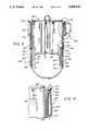
- FIG. 3is a cross-sectional view taken along line 3--3 of FIG. 2;
- FIG. 4is an enlarged view , a portion of the ankle brace in FIG. 3 as indicated by the oval designated 4 in FIG. 3;
- FIG. 5is an elevational view of a portion of the ankle brace shown in FIG. 3;
- FIG. 6is an enlarged cross-sectional view taken along line 6--6 of FIG. 5;
- FIG. 7is an enlarged cross-sectional view taken along line 7--7 of FIG. 5;
- FIG. 8shows an alternative configuration of one part of the ankle brace
- FIG. 9is a view similar to FIG. 3, but showing the inner resilient strap arrangements.
- the orthopaedic device 10for applying pressure to a selected body portion, exemplarily shown in FIG. 1 as an ankle.
- the orthopaedic device 10includes a first bladder 12 having an interior chamber 14, a high viscosity gel or fluid 16 substantially filling the interior chamber 14 of the first bladder 12, a second bladder 18 having an interior chamber 20, means 22 for releasably securing the first bladder 12 adjacent the selected body portion, and means 24 for filling the interior chamber 20 of the second bladder 18 to apply compressive force upon the first bladder 12.
- the first bladder 12applies pressure to the selected body portion in- response to the compressive force. Accordingly, the first bladder 12 is dimensioned conform to said selected body portion.
- the high viscosity gel 16is selected to resist instantaneous forces incident upon said first bladder 12 yet it gradually forms about the selected body portion.
- the gelmay be sold under the brand name Elasto Gel, commercially available from Technologies Inc. of Kansas City, Mo.
- the above referenced Pat. No. 3,237,319discloses a variety of high viscosity materials which may be useful in practicing the present invention.
- the second bladder 18is juxtaposed with respect to the first bladder 12.
- the first bladder 12has a first wall 26 and a second wall 28, the first wall 26 having a peripheral edge 30 and the second wall 28 having a peripheral edge 32.
- the peripheral edge 30 of the first wall 26is sealingly affixed to the peripheral edge 32 of the second wall 28.
- each of the first wall 26 and the second wall 28may be formed from vinyl with their respective peripheral edges 30, 32 being conventionally sealed.
- Radio frequency (RF) sealingis one exemplary technique with which the peripheral edges 30, 32 of the first wall 26 and second wall 28 may be sealed together.
- the second bladder 18includes a first wall 34 and a second wall 36.
- the first wall 34having a peripheral edge 38 and a second wall 36 having a peripheral edge 40.
- the peripheral edge 38, 40 for each of the first wall 34 and second wall 36 of the second bladder 18are conventionally sealed.
- the interior chamber 20 of the second bladdermay be, in one embodiment of the present invention, filled with an air permeable foam (not shown).
- a single sheet of vinylmay form both the second wall 28 and first wall 34 with the respective edges being RF sealed as best seen in FIG. 8.
- each of the first bladder 12 and the second bladder 18are generally U-shaped.
- the second bladder 18is also dimensioned conventionally with the first bladder 12.
- the second wall 28 of the first bladder 12 and the first wall 34 of the second bladder 18are in a facing relationship to each other.
- the second wall 28 of the first bladder 12 and the first wall 34 of the second bladder 18may either be permanently affixed or releasably attached to each other, by Velcro pads or other suitable means. For example, it may be desirable to remove the first bladder to heat the gel 16 prior to use of the orthopedic device 10.
- inflating means 24includes a grommet 42 received through an opening 44 in the second wall 36 of the second bladder 18.
- Grommet 42accordingly has a tubular portion 46 and an annular flange 48 affixed to an inner surface 50 of the second wall 36.
- Inflating means 24further includes a one-way air valve 52 having an inlet 54 and an outlet 56, a tube 58 operatively attached between the grommet 42 and the outlet 56.
- the tube 58is releasably fitted to the grommet 42 after being slidably received over the tubular portion 46.
- Inflating means 24further includes an air pump 60 operatively coupled to the inlet 54 of the one-way air valve 52.
- Air pump 60includes a squeeze bulb 62 and a second one-way air valve 64. Squeezing of the bulb 62 evacuate air therein through the first one-way air valve 52 to inflate the second bladder 18. Conversely, releasing of the squeeze bulb 62 causes air to fill the bulb 62 through the second one-way air valve 64.
- a release plug 65 for releasing air pressure from the interior chamber of the second bladder 18may also be provided.
- Securing means 22includes a flexible brace 66 adapted for being disposed about lower extremity of a body.
- the outer casing of the brace 66may be formed of canvas or similar material which is flexible but not stretchable to any significant extent.
- the brace 66includes a pair of opposed sidewall portions 68, each of the sidewall 68 having a rear edge 70 elastically coupled to each other, an inner surface 72 and an outer surface 74.
- Securing means 22further includes means 76 for adjusting the fit of the sidewall portions 68 about the lower extremity and means 78 for releasably attaching a separate bladder assembly to each inner surface 72 of each of the sidewall portions 68, in areas where the straps 91 and 93 are not interposed, and directly to the straps 91 and 93 where the straps are located between the bladders and the outer casing.
- the outer casing of the brace 66useful in practicing the present invention is disclosed in commonly owned co-pending patent application, Ser. No. 192,461, now U.S. Pat. No. 4,869,267, issued Sept. 26, 1984, commercially available from Surefit Orthopedics, known as the EXCEL Ankle Support System.
- the front edges of the outer casingmay be secured together by the straps 76 secured to the left front side of the casing, as shown in FIG. 1, passing through openings near the right front edge, and returning to overlap each strap and being secured thereto by matching Velcro pads, all as shown and discussed in U.S. Pat. No. 4,869,267.
- attaching means 78includes a mateable fastener 80 having a first mating member 82 and a second mating member 84.
- First mating member 82is mounted on the second wall 36 of the second bladder 18 the second mating matter is mounted on the inner surface 72 of the sidewall portion 68.
- the mateable fastener 80may be any conventional fastener commercially available under the Velcro trademark.
- Each sidewall portions 68includes a structural support 86 mounted on the outer surface 74 thereof. Structural support may be received by a pocket 88 sewn on to the outer surface 74 of each sidewall 68.
- the structural supportprovides rigidity for carrying the inflating means 24.
- the structural support 86carries the tube 58 which is received through an opening 90.
- FIG. 9 of the drawingsis a view similar to FIG. 3 of the drawings, but showing the broad, flexible elastic straps 91 and 93.
- These strapsextend from the rear lower edge of the brace, and are secured to the outer casing at the rear lower edge at the opening for accommodating the user's heel (see FIG. 2).
- the straps 91 and 93extend across one-another and overlap in a cruciate manner, and the lines 95 and 97, respectively, are secured to these straps.
- the elastic straps 91 and 93are located between the air bladders 18 and the side walls 68 of the casing 66.
- FIGS. 1 and 2the lines 95 and 97 are shown extending through openings in the outer casing of the brace 66, with D-rings 99 secured to the outer ends of lines 95 and 97.
- the laces 101 of the shoeare passed through the D-rings 99 and are tied together with tension to suit the needs of the user.
- appropriate supportmay be provided for the user, with the inner gel pads providing comfortable application of pressure or restraining force to the user's ankle.
- a zipper closuremay be provided toward the rear of the brace, as shown in FIGS. 2 and 3.
- the orthopaedic assembly of the present inventioncould have the D-rings 99 secured directly to the outer flexible casing, or to a resilient or flexible strap extending around and secured to the rear of the casing, with the inner cruciate straps omitted, and with the air bladders and inner resilient pads mounted to the inner surfaces of the flexible casing.
- the front edges of the flexible casingmay be held together by mating Velcro pads on the overlapping surfaces of the front edges, or by laces, instead of the use of straps as disclosed herein.
Landscapes
- Health & Medical Sciences (AREA)
- Public Health (AREA)
- General Health & Medical Sciences (AREA)
- Engineering & Computer Science (AREA)
- Nursing (AREA)
- Orthopedic Medicine & Surgery (AREA)
- Epidemiology (AREA)
- Biomedical Technology (AREA)
- Heart & Thoracic Surgery (AREA)
- Vascular Medicine (AREA)
- Life Sciences & Earth Sciences (AREA)
- Animal Behavior & Ethology (AREA)
- Veterinary Medicine (AREA)
- Orthopedics, Nursing, And Contraception (AREA)
Abstract
Description
Claims (28)
Priority Applications (1)
| Application Number | Priority Date | Filing Date | Title |
|---|---|---|---|
| US07/935,013USRE34661E (en) | 1988-05-10 | 1992-08-25 | Gel and air cushion ankle brace |
Applications Claiming Priority (2)
| Application Number | Priority Date | Filing Date | Title |
|---|---|---|---|
| US07/192,461US4869267A (en) | 1988-05-10 | 1988-05-10 | Adjustable tension ankle support |
| US30868989A | 1989-02-08 | 1989-02-08 |
Related Parent Applications (2)
| Application Number | Title | Priority Date | Filing Date |
|---|---|---|---|
| US07/192,461Continuation-In-PartUS4869267A (en) | 1988-05-10 | 1988-05-10 | Adjustable tension ankle support |
| US30868989AContinuation-In-Part | 1988-05-10 | 1989-02-08 |
Related Child Applications (1)
| Application Number | Title | Priority Date | Filing Date |
|---|---|---|---|
| US07/935,013ReissueUSRE34661E (en) | 1988-05-10 | 1992-08-25 | Gel and air cushion ankle brace |
Publications (1)
| Publication Number | Publication Date |
|---|---|
| US5088478Atrue US5088478A (en) | 1992-02-18 |
Family
ID=26888092
Family Applications (1)
| Application Number | Title | Priority Date | Filing Date |
|---|---|---|---|
| US07/572,843CeasedUS5088478A (en) | 1988-05-10 | 1990-08-24 | Gel and air cushion ankle brace |
Country Status (1)
| Country | Link |
|---|---|
| US (1) | US5088478A (en) |
Cited By (107)
| Publication number | Priority date | Publication date | Assignee | Title |
|---|---|---|---|---|
| US5277695A (en)* | 1991-11-08 | 1994-01-11 | Aircast, Inc. | Adjustable ankle compress |
| US5316547A (en)* | 1992-07-01 | 1994-05-31 | Smith & Nephew Donjoy, Inc. | Orthopedic brace having pneumatic pads |
| US5334135A (en)* | 1993-02-16 | 1994-08-02 | Grim Tracy E | Formed resilient orthopaedic support |
| US5369807A (en)* | 1993-03-17 | 1994-12-06 | Cho; Kurt N. | Therapeutic glove |
| US5378223A (en)* | 1992-10-23 | 1995-01-03 | Royce Medical Company | Orthopedic support pad and method for providing semi-permanent relief zones |
| US5389065A (en)* | 1993-06-15 | 1995-02-14 | Aircast, Inc. | Ankle brace with ATF compression |
| US5407421A (en)* | 1994-05-18 | 1995-04-18 | Goldsmith; Seth | Compressive brace |
| US5415625A (en)* | 1992-07-01 | 1995-05-16 | Smith & Nephew Donjoy, Inc. | Orthopedic brace having a system of alternately inflatable or deflatable pneumatic pads for adjustable fitting of the brace to the body |
| US5425701A (en)* | 1994-01-21 | 1995-06-20 | Minnesota Mining And Manufacturing Company | Orthopedic brace having width adjusting vamp |
| US5437615A (en)* | 1993-10-19 | 1995-08-01 | Reebok International Ltd. | Inflatable support device |
| US5449005A (en)* | 1993-12-22 | 1995-09-12 | Echols; Tony R. | Removable, shoe interior ankle brace |
| US5449379A (en)* | 1993-07-21 | 1995-09-12 | Alternative Compression Technologies, Inc. | Apparatus for applying a desired temperature and pressure to an injured area |
| US5458565A (en)* | 1992-07-01 | 1995-10-17 | Smith & Nephew Donjoy Inc. | Osteoarthritic knee brace |
| US5501659A (en)* | 1993-02-08 | 1996-03-26 | Smith & Nephew Donjoy, Inc. | Ankle brace |
| US5520622A (en)* | 1992-07-01 | 1996-05-28 | Smith & Nephew Donjoy Inc. | Orthopedic brace having a pneumatic pad and associated pump |
| US5527269A (en)* | 1993-12-24 | 1996-06-18 | Medi Bayreuth Gmbh & Co. | Ankle joint orthesis |
| US5527268A (en)* | 1992-07-01 | 1996-06-18 | Smith & Nephew Donjoy Inc. | Orthopedic knee brace and associated knee condyle pad |
| US5617650A (en)* | 1992-10-23 | 1997-04-08 | Grim; Tracy E. | Vacuum formed conformable shoe |
| US5637077A (en)* | 1995-10-30 | 1997-06-10 | Smith & Nephew Casting, Inc. | Custom-molded ankle brace |
| US5695452A (en)* | 1993-02-16 | 1997-12-09 | Grim; Tracy E. | Formed resilient orthopaedic device |
| USD394110S (en) | 1997-05-14 | 1998-05-05 | Parker Medical Associates Limited Partnership | Ankle brace |
| USD394112S (en) | 1997-05-14 | 1998-05-05 | Parker Medical Associates | Ankle brace |
| USD394905S (en) | 1997-05-14 | 1998-06-02 | Parker Medical Associates | Ankle brace |
| US5853381A (en)* | 1997-07-24 | 1998-12-29 | Tecnol Medical Products, Inc. | Ankle support brace |
| US5885230A (en)* | 1997-05-21 | 1999-03-23 | Cherry; Veronica | External gastroesophageal valve closer |
| US5957871A (en)* | 1998-03-27 | 1999-09-28 | Smith & Nephew, Inc. | Custom-fitted ankle splint product |
| US5980474A (en)* | 1998-03-27 | 1999-11-09 | Smith & Nephew, Inc. | Custom-fitted ankle splint |
| US6007506A (en)* | 1996-07-10 | 1999-12-28 | Heil; Dean | Method of using a shoe & support device |
| US6022331A (en)* | 1998-03-27 | 2000-02-08 | Smith & Nephew, Inc. | Custom-fitted ankle splint |
| DE19844545A1 (en)* | 1998-09-29 | 2000-03-30 | Thaemert Orthopaedische Hilfsmittel Gmbh & Co Kg | Knee joint supporting device uses elastic belt, positioned crosswise at back of knee area and several other supporting elements |
| US6117164A (en) | 1997-06-06 | 2000-09-12 | Dj Orthopedics, Llc | Flexible multijoint therapeutic pads |
| US6126625A (en)* | 1997-03-19 | 2000-10-03 | Lundberg; Leslie C. | Orthotic device for a joint of the human body |
| US6189172B1 (en) | 2000-01-14 | 2001-02-20 | Dc Shoes, Inc. | Removable liner and inflatable bladder for snowboard boots and method of manufacture |
| EP0825368A4 (en)* | 1995-04-28 | 2001-05-16 | Burlington Cons Ltd Inc | Body protective device |
| DE10029447A1 (en)* | 2000-02-23 | 2001-08-30 | Boesl Medizintechnik Gmbh | Girdle type collar for placing round the hips, arms or legs has fastening with adjustment, chambers, and chamber partitions |
| US6464658B1 (en) | 2000-12-07 | 2002-10-15 | Bsn Medical Inc. | Custom-formable knee immobilizer product, knee immobilizer and method |
| US6494418B1 (en) | 1996-02-06 | 2002-12-17 | 3M Innovative Properties Company | Wrist rest assembly |
| US6554785B1 (en) | 2000-10-13 | 2003-04-29 | Jon W. Sroufe | Therapeutic combination gel and air bladder pack |
| US20040064195A1 (en)* | 2002-07-15 | 2004-04-01 | Hugh Herr | Variable-mechanical-impedance artificial legs |
| USD493027S1 (en) | 2002-12-18 | 2004-07-20 | Arlan Dean Heil | Foot lift shoe |
| US20040181156A1 (en)* | 2002-12-16 | 2004-09-16 | Kingsford Howard A. | Inflatable products and methods of their formation and use |
| US20050177083A1 (en)* | 2004-02-09 | 2005-08-11 | Heil Arlan D. | Foot eversion inhibitor |
| US20050240135A1 (en)* | 2004-04-21 | 2005-10-27 | Carl Hoffmeier | Osteoarthritis brace |
| US20050252041A1 (en)* | 2004-05-14 | 2005-11-17 | Ramsey Makray D | Uni-sex multi-sport footwear accessory |
| US20060084899A1 (en)* | 2004-10-04 | 2006-04-20 | Verkade Drew R | Hinged ankle brace |
| US20060189907A1 (en)* | 2005-01-21 | 2006-08-24 | Aircast Llc | Brace having inflatable support |
| US20070010770A1 (en)* | 2005-07-07 | 2007-01-11 | Gildersleeve Richard E | Pneumatic liner with pressure relief valve and method of supporting an extremity with a pneumatic liner with pressure relief valve |
| US20070102106A1 (en)* | 2002-12-16 | 2007-05-10 | Velcro Industries B.V. | Medical Wraps |
| US20070186449A1 (en)* | 2006-02-13 | 2007-08-16 | Wilcots Cedric D | Athletic footwear securing device |
| US20070197950A1 (en)* | 2006-02-21 | 2007-08-23 | Wendell-Alan Ltd. | Device for administering cold therapy to ankles |
| US20070216203A1 (en)* | 2005-04-25 | 2007-09-20 | Rajasingham Arjuna I | Vehicle occupant support |
| USD552743S1 (en) | 2005-10-04 | 2007-10-09 | Djo, Llc | Ankle brace |
| USD552744S1 (en) | 2005-10-04 | 2007-10-09 | Djo, Llc | Ankle brace |
| WO2007075467A3 (en)* | 2005-12-19 | 2008-01-03 | Arjuna Indraeswara Rajasingham | Vehicle occupant support |
| US20080086070A1 (en)* | 2006-10-06 | 2008-04-10 | National Jewish Medical And Research Center | Joint Aspirate Facilitating Device |
| US20090131935A1 (en)* | 2007-11-15 | 2009-05-21 | Yeager David A | Method of preparing a patient's leg in need of treatment, for ambulation |
| US20090227927A1 (en)* | 2008-03-10 | 2009-09-10 | Frazer Michael J | Orthopedic walking brace |
| US20090247922A1 (en)* | 2008-03-26 | 2009-10-01 | Deroyal Industries, Inc. | Ankle support with calcaneous control strap |
| US20090247920A1 (en)* | 2008-03-26 | 2009-10-01 | Deroyal Industries, Inc. | Ankle Support with Calcaneous Control Strap |
| US20100114329A1 (en)* | 2005-03-31 | 2010-05-06 | Iwalk, Inc. | Hybrid terrain-adaptive lower-extremity systems |
| US20100113980A1 (en)* | 2008-09-04 | 2010-05-06 | Iwalk, Inc. | Hybrid Terrain-Adaptive Lower-Extremity Systems |
| US20100137770A1 (en)* | 2008-12-02 | 2010-06-03 | Arni Thor Ingimundarson | Ankle brace |
| USD618359S1 (en) | 2009-09-14 | 2010-06-22 | Ossur Hf | Expansion part for orthopedic device |
| USD620124S1 (en) | 2009-09-14 | 2010-07-20 | Ossur Hf | Orthopedic device |
| US20100241242A1 (en)* | 2005-03-31 | 2010-09-23 | Massachusetts Institute Of Technology | Artificial Joints Using Agonist-Antagonist Actuators |
| US20100312363A1 (en)* | 2005-03-31 | 2010-12-09 | Massachusetts Institute Of Technology | Powered Artificial Knee with Agonist-Antagonist Actuation |
| US20100324699A1 (en)* | 2005-03-31 | 2010-12-23 | Massachusetts Institute Of Technology | Model-Based Neuromechanical Controller for a Robotic Leg |
| US20110028877A1 (en)* | 2007-11-28 | 2011-02-03 | Otto Bock Healthcare Gmbh | Orthotic system for an ankle joint |
| US20110040216A1 (en)* | 2005-03-31 | 2011-02-17 | Massachusetts Institute Of Technology | Exoskeletons for running and walking |
| US20110082566A1 (en)* | 2008-09-04 | 2011-04-07 | Herr Hugh M | Implementing a stand-up sequence using a lower-extremity prosthesis or orthosis |
| US8287477B1 (en) | 2003-09-25 | 2012-10-16 | Massachusetts Institute Of Technology | Active ankle foot orthosis |
| US8512415B2 (en) | 2005-03-31 | 2013-08-20 | Massachusetts Institute Of Technology | Powered ankle-foot prothesis |
| US8690237B2 (en) | 2012-06-07 | 2014-04-08 | Graco Children's Products Inc. | Child car seat and headrest with side impact energy absorption |
| US8734528B2 (en) | 2005-03-31 | 2014-05-27 | Massachusetts Institute Of Technology | Artificial ankle-foot system with spring, variable-damping, and series-elastic actuator components |
| US9032635B2 (en) | 2011-12-15 | 2015-05-19 | Massachusetts Institute Of Technology | Physiological measurement device or wearable device interface simulator and method of use |
| US9060883B2 (en) | 2011-03-11 | 2015-06-23 | Iwalk, Inc. | Biomimetic joint actuators |
| US9221177B2 (en) | 2012-04-18 | 2015-12-29 | Massachusetts Institute Of Technology | Neuromuscular model-based sensing and control paradigm for a robotic leg |
| US9248042B2 (en) | 2012-09-12 | 2016-02-02 | Yessenia Lopez | Dorsal foot splint |
| US9308111B1 (en) | 2015-04-17 | 2016-04-12 | Andrew D. Mirabella | Orthopedic brace and method of use |
| US9333097B2 (en) | 2005-03-31 | 2016-05-10 | Massachusetts Institute Of Technology | Artificial human limbs and joints employing actuators, springs, and variable-damper elements |
| US20160128858A1 (en)* | 2014-03-06 | 2016-05-12 | Tyrone Wilson | Shoe Interfaced Ankle Support Apparatus |
| WO2016097821A1 (en) | 2014-12-17 | 2016-06-23 | Mcm Techno Consulting S.R.L. | Footwear provided with a device for pressure massage of the lower limbs |
| US9427350B1 (en) | 2012-12-20 | 2016-08-30 | Deroyal Industries, Inc. | Ankle support with cable reel |
| US9492305B2 (en) | 2013-03-15 | 2016-11-15 | Ortho Systems | Orthopedic walking boot with heel cushion |
| US9510965B2 (en) | 2014-07-01 | 2016-12-06 | Ortho Systems | Adjustable walking apparatus |
| US9687377B2 (en) | 2011-01-21 | 2017-06-27 | Bionx Medical Technologies, Inc. | Terrain adaptive powered joint orthosis |
| US9693883B2 (en) | 2010-04-05 | 2017-07-04 | Bionx Medical Technologies, Inc. | Controlling power in a prosthesis or orthosis based on predicted walking speed or surrogate for same |
| US9737419B2 (en) | 2011-11-02 | 2017-08-22 | Bionx Medical Technologies, Inc. | Biomimetic transfemoral prosthesis |
| US9839552B2 (en) | 2011-01-10 | 2017-12-12 | Bionx Medical Technologies, Inc. | Powered joint orthosis |
| WO2018081265A1 (en)* | 2016-10-31 | 2018-05-03 | University Of Florida Research Foundation, Inc. | Liquid prophylactic ankle brace |
| US10039664B2 (en) | 2013-03-15 | 2018-08-07 | Ortho Systems | Overmolding for an orthopedic walking boot |
| USD846130S1 (en) | 2018-01-31 | 2019-04-16 | Ortho Systems | Knee brace |
| US10271981B2 (en) | 2013-03-15 | 2019-04-30 | First Principles, Inc. | Combination wound and injury treatment apparatus |
| US10307272B2 (en) | 2005-03-31 | 2019-06-04 | Massachusetts Institute Of Technology | Method for using a model-based controller for a robotic leg |
| US10449078B2 (en) | 2013-03-15 | 2019-10-22 | Ovation Medical | Modular system for an orthopedic walking boot |
| US10531965B2 (en) | 2012-06-12 | 2020-01-14 | Bionx Medical Technologies, Inc. | Prosthetic, orthotic or exoskeleton device |
| US10537449B2 (en) | 2011-01-12 | 2020-01-21 | Bionx Medical Technologies, Inc. | Controlling powered human augmentation devices |
| US10842653B2 (en) | 2007-09-19 | 2020-11-24 | Ability Dynamics, Llc | Vacuum system for a prosthetic foot |
| US10863791B2 (en) | 2011-04-07 | 2020-12-15 | Ovation Medical | Removable leg walker |
| CN112754745A (en)* | 2021-02-01 | 2021-05-07 | 上海市同济医院 | Foot and ankle fixing device of lower limb traction bed |
| US20210274879A1 (en)* | 2020-03-03 | 2021-09-09 | Actiweight Labs AS | Footwear |
| US11246728B2 (en) | 2016-11-21 | 2022-02-15 | Aegis Biomechanics, Llc | Ankle brace |
| US11278433B2 (en) | 2005-03-31 | 2022-03-22 | Massachusetts Institute Of Technology | Powered ankle-foot prosthesis |
| CN114680424A (en)* | 2022-04-14 | 2022-07-01 | 浙江大学 | A dynamically adjusted flexible arch-ankle system and its control method |
| USD1030075S1 (en)* | 2022-08-04 | 2024-06-04 | Sara Frances Brown | Ankle support device |
| US12064366B2 (en) | 2021-03-11 | 2024-08-20 | G Force Braces, Llc | Therapy boot with pockets for ice pack and compression bladder |
| US20250303263A1 (en)* | 2024-04-02 | 2025-10-02 | Nike, Inc. | Vacuum locking for article of athletic equipment |
Citations (9)
| Publication number | Priority date | Publication date | Assignee | Title |
|---|---|---|---|---|
| US3901225A (en)* | 1974-01-02 | 1975-08-26 | Jerry W Sconce | Inflatable splint |
| US4411077A (en)* | 1982-01-05 | 1983-10-25 | Slavitt Jerome A | Athletic shoe with attached ankle brace |
| US4495942A (en)* | 1981-12-04 | 1985-01-29 | Palumbo Pasquale M | Dynamic ankle brace |
| US4502470A (en)* | 1982-09-16 | 1985-03-05 | Kiser John L | Physiologic device and method of treating the leg extremities |
| US4628945A (en)* | 1985-01-25 | 1986-12-16 | Johnson Jr Glenn W | Inflatable ankle brace with porous compressible filler |
| US4844094A (en)* | 1987-05-29 | 1989-07-04 | Royce Medical Company | Ankle brace |
| US4869267A (en)* | 1988-05-10 | 1989-09-26 | Royce Medical Company | Adjustable tension ankle support |
| US4964402A (en)* | 1988-08-17 | 1990-10-23 | Royce Medical Company | Orthopedic device having gel pad with phase change material |
| US4993409A (en)* | 1989-02-08 | 1991-02-19 | Royce Medical Company | Back support |
- 1990
- 1990-08-24USUS07/572,843patent/US5088478A/ennot_activeCeased
Patent Citations (9)
| Publication number | Priority date | Publication date | Assignee | Title |
|---|---|---|---|---|
| US3901225A (en)* | 1974-01-02 | 1975-08-26 | Jerry W Sconce | Inflatable splint |
| US4495942A (en)* | 1981-12-04 | 1985-01-29 | Palumbo Pasquale M | Dynamic ankle brace |
| US4411077A (en)* | 1982-01-05 | 1983-10-25 | Slavitt Jerome A | Athletic shoe with attached ankle brace |
| US4502470A (en)* | 1982-09-16 | 1985-03-05 | Kiser John L | Physiologic device and method of treating the leg extremities |
| US4628945A (en)* | 1985-01-25 | 1986-12-16 | Johnson Jr Glenn W | Inflatable ankle brace with porous compressible filler |
| US4844094A (en)* | 1987-05-29 | 1989-07-04 | Royce Medical Company | Ankle brace |
| US4869267A (en)* | 1988-05-10 | 1989-09-26 | Royce Medical Company | Adjustable tension ankle support |
| US4964402A (en)* | 1988-08-17 | 1990-10-23 | Royce Medical Company | Orthopedic device having gel pad with phase change material |
| US4993409A (en)* | 1989-02-08 | 1991-02-19 | Royce Medical Company | Back support |
Cited By (179)
| Publication number | Priority date | Publication date | Assignee | Title |
|---|---|---|---|---|
| US5277695A (en)* | 1991-11-08 | 1994-01-11 | Aircast, Inc. | Adjustable ankle compress |
| US5520622A (en)* | 1992-07-01 | 1996-05-28 | Smith & Nephew Donjoy Inc. | Orthopedic brace having a pneumatic pad and associated pump |
| US5316547A (en)* | 1992-07-01 | 1994-05-31 | Smith & Nephew Donjoy, Inc. | Orthopedic brace having pneumatic pads |
| US5415625A (en)* | 1992-07-01 | 1995-05-16 | Smith & Nephew Donjoy, Inc. | Orthopedic brace having a system of alternately inflatable or deflatable pneumatic pads for adjustable fitting of the brace to the body |
| US5527268A (en)* | 1992-07-01 | 1996-06-18 | Smith & Nephew Donjoy Inc. | Orthopedic knee brace and associated knee condyle pad |
| US5458565A (en)* | 1992-07-01 | 1995-10-17 | Smith & Nephew Donjoy Inc. | Osteoarthritic knee brace |
| US5378223A (en)* | 1992-10-23 | 1995-01-03 | Royce Medical Company | Orthopedic support pad and method for providing semi-permanent relief zones |
| US5617650A (en)* | 1992-10-23 | 1997-04-08 | Grim; Tracy E. | Vacuum formed conformable shoe |
| US5501659A (en)* | 1993-02-08 | 1996-03-26 | Smith & Nephew Donjoy, Inc. | Ankle brace |
| US5334135A (en)* | 1993-02-16 | 1994-08-02 | Grim Tracy E | Formed resilient orthopaedic support |
| US5695452A (en)* | 1993-02-16 | 1997-12-09 | Grim; Tracy E. | Formed resilient orthopaedic device |
| US5369807A (en)* | 1993-03-17 | 1994-12-06 | Cho; Kurt N. | Therapeutic glove |
| US5389065A (en)* | 1993-06-15 | 1995-02-14 | Aircast, Inc. | Ankle brace with ATF compression |
| US5449379A (en)* | 1993-07-21 | 1995-09-12 | Alternative Compression Technologies, Inc. | Apparatus for applying a desired temperature and pressure to an injured area |
| US5437615A (en)* | 1993-10-19 | 1995-08-01 | Reebok International Ltd. | Inflatable support device |
| US5449005A (en)* | 1993-12-22 | 1995-09-12 | Echols; Tony R. | Removable, shoe interior ankle brace |
| US5527269A (en)* | 1993-12-24 | 1996-06-18 | Medi Bayreuth Gmbh & Co. | Ankle joint orthesis |
| US5425701A (en)* | 1994-01-21 | 1995-06-20 | Minnesota Mining And Manufacturing Company | Orthopedic brace having width adjusting vamp |
| US5407421A (en)* | 1994-05-18 | 1995-04-18 | Goldsmith; Seth | Compressive brace |
| US6843454B2 (en) | 1994-06-03 | 2005-01-18 | 3M Innovative Properties Company | Method of assembling a wrist rest |
| US20040035986A1 (en)* | 1994-06-03 | 2004-02-26 | 3M Innovative Properties Company | Wrist rest assembly |
| US6626403B1 (en) | 1994-06-03 | 2003-09-30 | 3M Innovative Properties Company | Wrist rest assembly |
| EP0825368A4 (en)* | 1995-04-28 | 2001-05-16 | Burlington Cons Ltd Inc | Body protective device |
| US5637077A (en)* | 1995-10-30 | 1997-06-10 | Smith & Nephew Casting, Inc. | Custom-molded ankle brace |
| US6494418B1 (en) | 1996-02-06 | 2002-12-17 | 3M Innovative Properties Company | Wrist rest assembly |
| US6007506A (en)* | 1996-07-10 | 1999-12-28 | Heil; Dean | Method of using a shoe & support device |
| US6126625A (en)* | 1997-03-19 | 2000-10-03 | Lundberg; Leslie C. | Orthotic device for a joint of the human body |
| USD394112S (en) | 1997-05-14 | 1998-05-05 | Parker Medical Associates | Ankle brace |
| USD394905S (en) | 1997-05-14 | 1998-06-02 | Parker Medical Associates | Ankle brace |
| USD394110S (en) | 1997-05-14 | 1998-05-05 | Parker Medical Associates Limited Partnership | Ankle brace |
| US5885230A (en)* | 1997-05-21 | 1999-03-23 | Cherry; Veronica | External gastroesophageal valve closer |
| US6352550B1 (en) | 1997-06-06 | 2002-03-05 | Dj Orthopedics, Llc | Flexible multijoint therapeutic pads |
| US6117164A (en) | 1997-06-06 | 2000-09-12 | Dj Orthopedics, Llc | Flexible multijoint therapeutic pads |
| US5853381A (en)* | 1997-07-24 | 1998-12-29 | Tecnol Medical Products, Inc. | Ankle support brace |
| US5980474A (en)* | 1998-03-27 | 1999-11-09 | Smith & Nephew, Inc. | Custom-fitted ankle splint |
| US6022331A (en)* | 1998-03-27 | 2000-02-08 | Smith & Nephew, Inc. | Custom-fitted ankle splint |
| US5957871A (en)* | 1998-03-27 | 1999-09-28 | Smith & Nephew, Inc. | Custom-fitted ankle splint product |
| DE19844545A1 (en)* | 1998-09-29 | 2000-03-30 | Thaemert Orthopaedische Hilfsmittel Gmbh & Co Kg | Knee joint supporting device uses elastic belt, positioned crosswise at back of knee area and several other supporting elements |
| DE19844545B4 (en)* | 1998-09-29 | 2006-08-03 | Thämert Orthopädische Hilfsmittel GmbH & Co. KG | joint orthosis |
| US6766599B2 (en) | 2000-01-14 | 2004-07-27 | Dc Shoes, Inc. | Removable liner and inflatable bladder for snowboard boots and method of manufacture |
| US7010823B2 (en) | 2000-01-14 | 2006-03-14 | Dc Shoes, Inc. | Removable liner and inflatable bladder for snowboard boots and method of manufacture |
| US20040261202A1 (en)* | 2000-01-14 | 2004-12-30 | Dc Shoes, Inc. | Removable liner and inflatable bladder for snowboard boots and method of manufacture |
| US6189172B1 (en) | 2000-01-14 | 2001-02-20 | Dc Shoes, Inc. | Removable liner and inflatable bladder for snowboard boots and method of manufacture |
| DE10029447A1 (en)* | 2000-02-23 | 2001-08-30 | Boesl Medizintechnik Gmbh | Girdle type collar for placing round the hips, arms or legs has fastening with adjustment, chambers, and chamber partitions |
| US6554785B1 (en) | 2000-10-13 | 2003-04-29 | Jon W. Sroufe | Therapeutic combination gel and air bladder pack |
| US6712780B2 (en) | 2000-12-07 | 2004-03-30 | Bsn Medical Inc. | Custom-formable knee immobilizer product, knee immobilizer and method |
| US6464658B1 (en) | 2000-12-07 | 2002-10-15 | Bsn Medical Inc. | Custom-formable knee immobilizer product, knee immobilizer and method |
| US20040064195A1 (en)* | 2002-07-15 | 2004-04-01 | Hugh Herr | Variable-mechanical-impedance artificial legs |
| US8551184B1 (en) | 2002-07-15 | 2013-10-08 | Iwalk, Inc. | Variable mechanical-impedance artificial legs |
| US8231816B2 (en) | 2002-12-16 | 2012-07-31 | Velcro Industries B.V. | Medical wraps |
| US20070102106A1 (en)* | 2002-12-16 | 2007-05-10 | Velcro Industries B.V. | Medical Wraps |
| US8314283B2 (en) | 2002-12-16 | 2012-11-20 | Velcro Industries B.V. | Medical wraps |
| US20090165922A1 (en)* | 2002-12-16 | 2009-07-02 | Velcro Industries B.V. | Medical Wraps |
| US20060162288A1 (en)* | 2002-12-16 | 2006-07-27 | Kingsford Howard A | Attachable bags |
| US20040181156A1 (en)* | 2002-12-16 | 2004-09-16 | Kingsford Howard A. | Inflatable products and methods of their formation and use |
| USD493027S1 (en) | 2002-12-18 | 2004-07-20 | Arlan Dean Heil | Foot lift shoe |
| US10695256B2 (en) | 2003-09-25 | 2020-06-30 | Massachusetts Institute Of Technology | Motorized limb assistance device |
| US8287477B1 (en) | 2003-09-25 | 2012-10-16 | Massachusetts Institute Of Technology | Active ankle foot orthosis |
| US9668888B2 (en) | 2003-09-25 | 2017-06-06 | Massachusetts Institute Of Technology | Active ankle foot orthosis |
| US8808214B2 (en) | 2003-09-25 | 2014-08-19 | Massachusetts Institute Of Technology | Active ankle foot orthosis |
| US8376971B1 (en) | 2003-09-25 | 2013-02-19 | Massachusetts Institute Of Technology | Active ankle foot orthosis |
| US8551029B1 (en) | 2003-09-25 | 2013-10-08 | Massachusetts Institute Of Technology | Active ankle foot orthosis |
| US20050177083A1 (en)* | 2004-02-09 | 2005-08-11 | Heil Arlan D. | Foot eversion inhibitor |
| US20070060852A1 (en)* | 2004-02-09 | 2007-03-15 | Heil Arlan D | Footwear and foot movement inhibitor |
| US20050240135A1 (en)* | 2004-04-21 | 2005-10-27 | Carl Hoffmeier | Osteoarthritis brace |
| US7311687B2 (en) | 2004-04-21 | 2007-12-25 | Djo, Llc | Osteoarthritis brace |
| US20050252041A1 (en)* | 2004-05-14 | 2005-11-17 | Ramsey Makray D | Uni-sex multi-sport footwear accessory |
| US20060084899A1 (en)* | 2004-10-04 | 2006-04-20 | Verkade Drew R | Hinged ankle brace |
| US8641654B2 (en) | 2004-10-04 | 2014-02-04 | Djo, Llc | Hinged ankle brace |
| US9364366B2 (en) | 2004-10-04 | 2016-06-14 | Djo, Llc | Hinged ankle brace |
| US10463523B2 (en) | 2004-10-04 | 2019-11-05 | Djo, Llc | Hinged ankle brace |
| US11039948B2 (en) | 2004-10-04 | 2021-06-22 | Djo, Llc | Hinged ankle brace |
| US20060189907A1 (en)* | 2005-01-21 | 2006-08-24 | Aircast Llc | Brace having inflatable support |
| US8226585B2 (en)* | 2005-01-21 | 2012-07-24 | Djo, Llc | Brace having inflatable support |
| US20110040216A1 (en)* | 2005-03-31 | 2011-02-17 | Massachusetts Institute Of Technology | Exoskeletons for running and walking |
| US20100324699A1 (en)* | 2005-03-31 | 2010-12-23 | Massachusetts Institute Of Technology | Model-Based Neuromechanical Controller for a Robotic Leg |
| US20100114329A1 (en)* | 2005-03-31 | 2010-05-06 | Iwalk, Inc. | Hybrid terrain-adaptive lower-extremity systems |
| US11491032B2 (en) | 2005-03-31 | 2022-11-08 | Massachusetts Institute Of Technology | Artificial joints using agonist-antagonist actuators |
| US11278433B2 (en) | 2005-03-31 | 2022-03-22 | Massachusetts Institute Of Technology | Powered ankle-foot prosthesis |
| US11273060B2 (en) | 2005-03-31 | 2022-03-15 | Massachusetts Institute Of Technology | Artificial ankle-foot system with spring, variable-damping, and series-elastic actuator components |
| US8512415B2 (en) | 2005-03-31 | 2013-08-20 | Massachusetts Institute Of Technology | Powered ankle-foot prothesis |
| US9339397B2 (en) | 2005-03-31 | 2016-05-17 | Massachusetts Institute Of Technology | Artificial ankle-foot system with spring, variable-damping, and series-elastic actuator components |
| US10342681B2 (en) | 2005-03-31 | 2019-07-09 | Massachusetts Institute Of Technology | Artificial ankle-foot system with spring, variable-damping, and series-elastic actuator components |
| US10588759B2 (en) | 2005-03-31 | 2020-03-17 | Massachusetts Institute Of Technology | Artificial human limbs and joints employing actuators, springs and variable-damper elements |
| US20100241242A1 (en)* | 2005-03-31 | 2010-09-23 | Massachusetts Institute Of Technology | Artificial Joints Using Agonist-Antagonist Actuators |
| US9539117B2 (en) | 2005-03-31 | 2017-01-10 | Massachusetts Institute Of Technology | Method for controlling a robotic limb joint |
| US20100312363A1 (en)* | 2005-03-31 | 2010-12-09 | Massachusetts Institute Of Technology | Powered Artificial Knee with Agonist-Antagonist Actuation |
| US8500823B2 (en) | 2005-03-31 | 2013-08-06 | Massachusetts Institute Of Technology | Powered artificial knee with agonist-antagonist actuation |
| US9149370B2 (en) | 2005-03-31 | 2015-10-06 | Massachusetts Institute Of Technology | Powered artificial knee with agonist-antagonist actuation |
| US10307272B2 (en) | 2005-03-31 | 2019-06-04 | Massachusetts Institute Of Technology | Method for using a model-based controller for a robotic leg |
| US10485681B2 (en) | 2005-03-31 | 2019-11-26 | Massachusetts Institute Of Technology | Exoskeletons for running and walking |
| US10080672B2 (en) | 2005-03-31 | 2018-09-25 | Bionx Medical Technologies, Inc. | Hybrid terrain-adaptive lower-extremity systems |
| US8870967B2 (en) | 2005-03-31 | 2014-10-28 | Massachusetts Institute Of Technology | Artificial joints using agonist-antagonist actuators |
| US8864846B2 (en) | 2005-03-31 | 2014-10-21 | Massachusetts Institute Of Technology | Model-based neuromechanical controller for a robotic leg |
| US9333097B2 (en) | 2005-03-31 | 2016-05-10 | Massachusetts Institute Of Technology | Artificial human limbs and joints employing actuators, springs, and variable-damper elements |
| US10137011B2 (en) | 2005-03-31 | 2018-11-27 | Massachusetts Institute Of Technology | Powered ankle-foot prosthesis |
| US8734528B2 (en) | 2005-03-31 | 2014-05-27 | Massachusetts Institute Of Technology | Artificial ankle-foot system with spring, variable-damping, and series-elastic actuator components |
| US8251444B2 (en)* | 2005-04-25 | 2012-08-28 | Arjuna Indraeswaran Rajasingham | Vehicle occupant support |
| US20070216203A1 (en)* | 2005-04-25 | 2007-09-20 | Rajasingham Arjuna I | Vehicle occupant support |
| US20070010770A1 (en)* | 2005-07-07 | 2007-01-11 | Gildersleeve Richard E | Pneumatic liner with pressure relief valve and method of supporting an extremity with a pneumatic liner with pressure relief valve |
| USD552744S1 (en) | 2005-10-04 | 2007-10-09 | Djo, Llc | Ankle brace |
| USD552743S1 (en) | 2005-10-04 | 2007-10-09 | Djo, Llc | Ankle brace |
| WO2007075467A3 (en)* | 2005-12-19 | 2008-01-03 | Arjuna Indraeswara Rajasingham | Vehicle occupant support |
| US20070186449A1 (en)* | 2006-02-13 | 2007-08-16 | Wilcots Cedric D | Athletic footwear securing device |
| US20070197950A1 (en)* | 2006-02-21 | 2007-08-23 | Wendell-Alan Ltd. | Device for administering cold therapy to ankles |
| US7481786B2 (en) | 2006-02-21 | 2009-01-27 | Wendell-Alan Ltd. | Device for administering cold therapy to ankles |
| US7468048B2 (en)* | 2006-10-06 | 2008-12-23 | National Jewish Health | Joint aspirate facilitating device |
| WO2008045762A3 (en)* | 2006-10-06 | 2008-06-26 | Nat Jewish Med & Res Center | Joint aspirate facilitating device |
| US20080086070A1 (en)* | 2006-10-06 | 2008-04-10 | National Jewish Medical And Research Center | Joint Aspirate Facilitating Device |
| US10842653B2 (en) | 2007-09-19 | 2020-11-24 | Ability Dynamics, Llc | Vacuum system for a prosthetic foot |
| WO2009064341A1 (en)* | 2007-11-15 | 2009-05-22 | Yeager David A | Method of preparing a patient's leg, in need of treatment, for ambulation |
| US7955333B2 (en) | 2007-11-15 | 2011-06-07 | Yeager David A | Method of preparing a patient's leg in need of treatment, for ambulation |
| US20090131935A1 (en)* | 2007-11-15 | 2009-05-21 | Yeager David A | Method of preparing a patient's leg in need of treatment, for ambulation |
| US9788987B2 (en)* | 2007-11-28 | 2017-10-17 | Otto Bock Healthcare Gmbh | Orthotic system for an ankle joint |
| US20110028877A1 (en)* | 2007-11-28 | 2011-02-03 | Otto Bock Healthcare Gmbh | Orthotic system for an ankle joint |
| US20090227927A1 (en)* | 2008-03-10 | 2009-09-10 | Frazer Michael J | Orthopedic walking brace |
| US20090247920A1 (en)* | 2008-03-26 | 2009-10-01 | Deroyal Industries, Inc. | Ankle Support with Calcaneous Control Strap |
| US8100845B2 (en) | 2008-03-26 | 2012-01-24 | Deroyal Industries, Inc. | Ankle support with calcaneous control strap |
| US20090247922A1 (en)* | 2008-03-26 | 2009-10-01 | Deroyal Industries, Inc. | Ankle support with calcaneous control strap |
| US7828758B2 (en) | 2008-03-26 | 2010-11-09 | Deroyal Industries, Inc. | Ankle support with calcaneous control strap |
| US8317735B2 (en) | 2008-03-26 | 2012-11-27 | Deroyal Industries, Inc. | Ankle support with calcaneous control strap |
| US8419804B2 (en) | 2008-09-04 | 2013-04-16 | Iwalk, Inc. | Hybrid terrain-adaptive lower-extremity systems |
| US20100179668A1 (en)* | 2008-09-04 | 2010-07-15 | Iwalk, Inc. | Hybrid Terrain-Adaptive Lower-Extremity Systems |
| US20100113980A1 (en)* | 2008-09-04 | 2010-05-06 | Iwalk, Inc. | Hybrid Terrain-Adaptive Lower-Extremity Systems |
| US20110082566A1 (en)* | 2008-09-04 | 2011-04-07 | Herr Hugh M | Implementing a stand-up sequence using a lower-extremity prosthesis or orthosis |
| US9345592B2 (en) | 2008-09-04 | 2016-05-24 | Bionx Medical Technologies, Inc. | Hybrid terrain-adaptive lower-extremity systems |
| US9351856B2 (en) | 2008-09-04 | 2016-05-31 | Iwalk, Inc. | Hybrid terrain-adaptive lower-extremity systems |
| US10070974B2 (en) | 2008-09-04 | 2018-09-11 | Bionx Medical Technologies, Inc. | Hybrid terrain-adaptive lower-extremity systems |
| US20100174384A1 (en)* | 2008-09-04 | 2010-07-08 | Iwalk, Inc. | Hybrid terrain-adaptive lower-extremity systems |
| US20100174385A1 (en)* | 2008-09-04 | 2010-07-08 | Iwalk, Inc. | Hybrid Terrain-Adaptive Lower-Extremity Systems |
| US8900325B2 (en) | 2008-09-04 | 2014-12-02 | Iwalk, Inc. | Hybrid terrain-adaptive lower-extremity systems |
| US10105244B2 (en) | 2008-09-04 | 2018-10-23 | Bionx Medical Technologies, Inc. | Hybrid terrain-adaptive lower-extremity systems |
| US9211201B2 (en) | 2008-09-04 | 2015-12-15 | Iwalk, Inc. | Hybrid terrain-adaptive lower-extremity systems |
| US9554922B2 (en) | 2008-09-04 | 2017-01-31 | Bionx Medical Technologies, Inc. | Hybrid terrain-adaptive lower-extremity systems |
| US10285828B2 (en) | 2008-09-04 | 2019-05-14 | Bionx Medical Technologies, Inc. | Implementing a stand-up sequence using a lower-extremity prosthesis or orthosis |
| US20100137770A1 (en)* | 2008-12-02 | 2010-06-03 | Arni Thor Ingimundarson | Ankle brace |
| US8622946B2 (en) | 2008-12-02 | 2014-01-07 | Ossur Hf | Ankle brace |
| US9907687B2 (en) | 2008-12-02 | 2018-03-06 | Ossur Hf | Ankle brace |
| USD673280S1 (en) | 2009-09-14 | 2012-12-25 | Ossur Hf | Orthopedic device |
| USD672878S1 (en) | 2009-09-14 | 2012-12-18 | Ossur Hf | Orthopedic device |
| USD620124S1 (en) | 2009-09-14 | 2010-07-20 | Ossur Hf | Orthopedic device |
| USD618359S1 (en) | 2009-09-14 | 2010-06-22 | Ossur Hf | Expansion part for orthopedic device |
| US10406002B2 (en) | 2010-04-05 | 2019-09-10 | Bionx Medical Technologies, Inc. | Controlling torque in a prosthesis or orthosis based on a deflection of series elastic element |
| US9693883B2 (en) | 2010-04-05 | 2017-07-04 | Bionx Medical Technologies, Inc. | Controlling power in a prosthesis or orthosis based on predicted walking speed or surrogate for same |
| US9839552B2 (en) | 2011-01-10 | 2017-12-12 | Bionx Medical Technologies, Inc. | Powered joint orthosis |
| US10537449B2 (en) | 2011-01-12 | 2020-01-21 | Bionx Medical Technologies, Inc. | Controlling powered human augmentation devices |
| US9687377B2 (en) | 2011-01-21 | 2017-06-27 | Bionx Medical Technologies, Inc. | Terrain adaptive powered joint orthosis |
| US9060883B2 (en) | 2011-03-11 | 2015-06-23 | Iwalk, Inc. | Biomimetic joint actuators |
| US9872782B2 (en) | 2011-03-11 | 2018-01-23 | Bionx Medical Technologies, Inc. | Biomimetic joint actuators |
| US10863791B2 (en) | 2011-04-07 | 2020-12-15 | Ovation Medical | Removable leg walker |
| US9737419B2 (en) | 2011-11-02 | 2017-08-22 | Bionx Medical Technologies, Inc. | Biomimetic transfemoral prosthesis |
| US9032635B2 (en) | 2011-12-15 | 2015-05-19 | Massachusetts Institute Of Technology | Physiological measurement device or wearable device interface simulator and method of use |
| US9221177B2 (en) | 2012-04-18 | 2015-12-29 | Massachusetts Institute Of Technology | Neuromuscular model-based sensing and control paradigm for a robotic leg |
| US9975249B2 (en) | 2012-04-18 | 2018-05-22 | Massachusetts Institute Of Technology | Neuromuscular model-based sensing and control paradigm for a robotic leg |
| US8690237B2 (en) | 2012-06-07 | 2014-04-08 | Graco Children's Products Inc. | Child car seat and headrest with side impact energy absorption |
| US10531965B2 (en) | 2012-06-12 | 2020-01-14 | Bionx Medical Technologies, Inc. | Prosthetic, orthotic or exoskeleton device |
| US9248042B2 (en) | 2012-09-12 | 2016-02-02 | Yessenia Lopez | Dorsal foot splint |
| US9427350B1 (en) | 2012-12-20 | 2016-08-30 | Deroyal Industries, Inc. | Ankle support with cable reel |
| US10449078B2 (en) | 2013-03-15 | 2019-10-22 | Ovation Medical | Modular system for an orthopedic walking boot |
| US10085871B2 (en) | 2013-03-15 | 2018-10-02 | Ovation Systems | Overmolding for an orthopedic walking boot |
| US10271981B2 (en) | 2013-03-15 | 2019-04-30 | First Principles, Inc. | Combination wound and injury treatment apparatus |
| US9492305B2 (en) | 2013-03-15 | 2016-11-15 | Ortho Systems | Orthopedic walking boot with heel cushion |
| US10039664B2 (en) | 2013-03-15 | 2018-08-07 | Ortho Systems | Overmolding for an orthopedic walking boot |
| US20160128858A1 (en)* | 2014-03-06 | 2016-05-12 | Tyrone Wilson | Shoe Interfaced Ankle Support Apparatus |
| US10449077B2 (en) | 2014-07-01 | 2019-10-22 | Ovation Medical | Adjustable walking apparatus |
| US9510965B2 (en) | 2014-07-01 | 2016-12-06 | Ortho Systems | Adjustable walking apparatus |
| WO2016097821A1 (en) | 2014-12-17 | 2016-06-23 | Mcm Techno Consulting S.R.L. | Footwear provided with a device for pressure massage of the lower limbs |
| US9308111B1 (en) | 2015-04-17 | 2016-04-12 | Andrew D. Mirabella | Orthopedic brace and method of use |
| WO2018081265A1 (en)* | 2016-10-31 | 2018-05-03 | University Of Florida Research Foundation, Inc. | Liquid prophylactic ankle brace |
| US11246728B2 (en) | 2016-11-21 | 2022-02-15 | Aegis Biomechanics, Llc | Ankle brace |
| USD846130S1 (en) | 2018-01-31 | 2019-04-16 | Ortho Systems | Knee brace |
| US20210274879A1 (en)* | 2020-03-03 | 2021-09-09 | Actiweight Labs AS | Footwear |
| US12178290B2 (en)* | 2020-03-03 | 2024-12-31 | Actiweight Labs AS | Footwear |
| CN112754745A (en)* | 2021-02-01 | 2021-05-07 | 上海市同济医院 | Foot and ankle fixing device of lower limb traction bed |
| US12064366B2 (en) | 2021-03-11 | 2024-08-20 | G Force Braces, Llc | Therapy boot with pockets for ice pack and compression bladder |
| US12357485B2 (en) | 2021-03-11 | 2025-07-15 | G Force Braces, Llc | Therapy boot with pockets for ice pack and compression bladder |
| CN114680424A (en)* | 2022-04-14 | 2022-07-01 | 浙江大学 | A dynamically adjusted flexible arch-ankle system and its control method |
| USD1030075S1 (en)* | 2022-08-04 | 2024-06-04 | Sara Frances Brown | Ankle support device |
| US20250303263A1 (en)* | 2024-04-02 | 2025-10-02 | Nike, Inc. | Vacuum locking for article of athletic equipment |
Similar Documents
| Publication | Publication Date | Title |
|---|---|---|
| US5088478A (en) | Gel and air cushion ankle brace | |
| USRE34661E (en) | Gel and air cushion ankle brace | |
| US5389065A (en) | Ankle brace with ATF compression | |
| US5577998A (en) | Walking brace | |
| US8597219B2 (en) | Fracture brace | |
| US4844094A (en) | Ankle brace | |
| US5348530A (en) | Pneumatic ankle brace with bladder and pump arrangement | |
| US20050145256A1 (en) | Orthopedic walker having a soft boot with a deformable insert | |
| AU663075B2 (en) | Thermal compress system | |
| US6554785B1 (en) | Therapeutic combination gel and air bladder pack | |
| AU2001217945B2 (en) | Orthopedic ankle brace | |
| US5113877A (en) | Ankle sprain management system | |
| US4378009A (en) | Brace for injured parts of the body | |
| US5464385A (en) | Walker with open heel | |
| US5014691A (en) | Ankle brace with densified batting | |
| CA2579659C (en) | Fracture brace | |
| US6306112B2 (en) | Bladder for orthopedic supports | |
| JPH09201378A (en) | Lower extremity walking tool | |
| AU2001217945A1 (en) | Orthopedic ankle brace | |
| JPH01503522A (en) | Orthopedic gel pad method and device | |
| US11432954B2 (en) | Inflatable flexion-correcting knee brace | |
| JPS6130580B2 (en) | ||
| US20060173393A1 (en) | Inflatable splint for stabilisation of the ankle | |
| CN221578325U (en) | Ankle joint physiotherapy equipment | |
| WO1994016589A1 (en) | Heel stabilizing device and method |
Legal Events
| Date | Code | Title | Description |
|---|---|---|---|
| AS | Assignment | Owner name:ROYCE MEDICAL COMPANY, CALIFORNIA Free format text:ASSIGNMENT OF ASSIGNORS INTEREST.;ASSIGNOR:GRIM, TRACY E.;REEL/FRAME:005425/0471 Effective date:19900823 | |
| STCF | Information on status: patent grant | Free format text:PATENTED CASE | |
| RF | Reissue application filed | Effective date:19920825 | |
| AS | Assignment | Owner name:U.S. BANK NATIONAL ASSOCIATION, CALIFORNIA Free format text:SECURITY INTEREST;ASSIGNOR:ROYCE MEDICAL COMPANY;REEL/FRAME:010742/0926 Effective date:20000406 | |
| AS | Assignment | Owner name:ANTARES CAPITAL CORPORATION, AS AGENT, ILLINOIS Free format text:SECURITY AGREEMENT;ASSIGNOR:ROYCE MEDICAL COMPANY;REEL/FRAME:014313/0001 Effective date:20030711 | |
| AS | Assignment | Owner name:ROYCE MEDICAL COMPANY, CALIFORNIA Free format text:PATENT RELEASE AND REASSIGNMENT;ASSIGNOR:ANTARES CAPITAL CORPORATION;REEL/FRAME:016408/0753 Effective date:20050810 | |
| AS | Assignment | Owner name:KAUPTHING BANK HF, NEW YORK Free format text:SECURITY AGREEMENT;ASSIGNOR:ROYCE MEDICAL COMPANY;REEL/FRAME:016610/0376 Effective date:20050901 | |
| AS | Assignment | Owner name:OSSUR HF, ICELAND Free format text:ASSIGNMENT OF ASSIGNORS INTEREST;ASSIGNOR:ROYCE MEDICAL COMPANY;REEL/FRAME:019028/0284 Effective date:20070308 |