US5086788A - Hand-held physiological stimulation applicator - Google Patents
Hand-held physiological stimulation applicatorDownload PDFInfo
- Publication number
- US5086788A US5086788AUS07/206,440US20644088AUS5086788AUS 5086788 AUS5086788 AUS 5086788AUS 20644088 AUS20644088 AUS 20644088AUS 5086788 AUS5086788 AUS 5086788A
- Authority
- US
- United States
- Prior art keywords
- transducer
- power source
- manually operable
- housing
- axis
- Prior art date
- Legal status (The legal status is an assumption and is not a legal conclusion. Google has not performed a legal analysis and makes no representation as to the accuracy of the status listed.)
- Expired - Lifetime
Links
- 230000000638stimulationEffects0.000titleclaimsabstractdescription35
- 239000004020conductorSubstances0.000claimsdescription11
- 230000001788irregularEffects0.000claimsdescription2
- 230000001815facial effectEffects0.000abstractdescription5
- 230000010355oscillationEffects0.000description5
- 239000013078crystalSubstances0.000description4
- 238000010276constructionMethods0.000description3
- 230000014759maintenance of locationEffects0.000description3
- 238000010586diagramMethods0.000description2
- 239000002184metalSubstances0.000description2
- 239000013641positive controlSubstances0.000description2
- 230000008878couplingEffects0.000description1
- 238000010168coupling processMethods0.000description1
- 238000005859coupling reactionMethods0.000description1
- 238000006073displacement reactionMethods0.000description1
- 230000000694effectsEffects0.000description1
- 230000001766physiological effectEffects0.000description1
- 230000000717retained effectEffects0.000description1
- 238000002604ultrasonographyMethods0.000description1
- XLYOFNOQVPJJNP-UHFFFAOYSA-NwaterSubstancesOXLYOFNOQVPJJNP-UHFFFAOYSA-N0.000description1
Images

Classifications
- A—HUMAN NECESSITIES
- A61—MEDICAL OR VETERINARY SCIENCE; HYGIENE
- A61H—PHYSICAL THERAPY APPARATUS, e.g. DEVICES FOR LOCATING OR STIMULATING REFLEX POINTS IN THE BODY; ARTIFICIAL RESPIRATION; MASSAGE; BATHING DEVICES FOR SPECIAL THERAPEUTIC OR HYGIENIC PURPOSES OR SPECIFIC PARTS OF THE BODY
- A61H23/00—Percussion or vibration massage, e.g. using supersonic vibration; Suction-vibration massage; Massage with moving diaphragms
- A61H23/02—Percussion or vibration massage, e.g. using supersonic vibration; Suction-vibration massage; Massage with moving diaphragms with electric or magnetic drive
- A61H23/0245—Percussion or vibration massage, e.g. using supersonic vibration; Suction-vibration massage; Massage with moving diaphragms with electric or magnetic drive with ultrasonic transducers, e.g. piezoelectric
- A—HUMAN NECESSITIES
- A61—MEDICAL OR VETERINARY SCIENCE; HYGIENE
- A61N—ELECTROTHERAPY; MAGNETOTHERAPY; RADIATION THERAPY; ULTRASOUND THERAPY
- A61N1/00—Electrotherapy; Circuits therefor
- A61N1/18—Applying electric currents by contact electrodes
- A61N1/32—Applying electric currents by contact electrodes alternating or intermittent currents
- A61N1/36—Applying electric currents by contact electrodes alternating or intermittent currents for stimulation
- A61N1/36014—External stimulators, e.g. with patch electrodes
- A61N1/3603—Control systems
- A61N1/36034—Control systems specified by the stimulation parameters
- A—HUMAN NECESSITIES
- A61—MEDICAL OR VETERINARY SCIENCE; HYGIENE
- A61H—PHYSICAL THERAPY APPARATUS, e.g. DEVICES FOR LOCATING OR STIMULATING REFLEX POINTS IN THE BODY; ARTIFICIAL RESPIRATION; MASSAGE; BATHING DEVICES FOR SPECIAL THERAPEUTIC OR HYGIENIC PURPOSES OR SPECIFIC PARTS OF THE BODY
- A61H2201/00—Characteristics of apparatus not provided for in the preceding codes
- A61H2201/10—Characteristics of apparatus not provided for in the preceding codes with further special therapeutic means, e.g. electrotherapy, magneto therapy or radiation therapy, chromo therapy, infrared or ultraviolet therapy
Definitions
- This inventionrelates to physiological stimuli applicators and in particular to hand-held physiological stimulation applicators.
- a power source adapted to provide high frequency sound vibrationsis provided with a transducer adapted to be electrically operated for producing mechanical vibrations at high frequency suitable to provide physiological stimulation and/or treatment of a patient's tissue.
- a hand-held signal applicatoris connected to the base unit by suitable electrical conductors and includes, at an end portion thereof, the transducer adapted to be urged against the patient's tissue for delivering the stimulation and/or treatment oscillation to the tissue.
- Suitable controlsare provided on the base unit for selecting different power levels and frequencies, as desired.
- the present inventioncomprehends an improved applicator for providing such high frequency oscillations either in the form of mechanical vibrations or electrical stimulation signals to the patient's tissue.
- the inventioncomprehends the provision of a manually operable apparatus for controlled physiological stimulation which includes an elongated housing having a first end defining an axis, an opposite second end, and a grasping portion intermediate the ends, an electrically operable transducer, mounting means for mounting the transducer to the first housing end, and means for energizing the transducer including a power source spaced from the housing, manually operable controls at the housing grasping portion, and electrical conductors for interconnecting the power source, controls, and transducer to permit concurrent controlled energization and physical positioning of the transducer by a user's hand embracing the housing grasping portion.
- the inventioncomprehends the provision of such an applicator which includes an elongated housing having a first end defining an axis, an opposite second end, and a grasping portion intermediate the ends, an electrically operable transducer, mounting means for mounting the transducer to the first housing end comprising means for directing the transducer at an angle to the axis selectively at any one of a plurality of portions circumferentially about the axis, and means for energizing the transducer including a power source, manually operable controls, and electrical conductors for interconnecting the power source, controls, and transducer to permit physical positioning of the transducer by a user's hand embracing the housing grasping portion with the transducer positioned at a preselected angle to the axis.
- the applicatorincludes both mounting means for mounting the transducer to the first housing end comprising means for directing the transducer at an angle to the axis selectively at any one of a plurality of positions circumferentially about the axis, and means for energizing the transducer including a power source spaced from the housing manually operable controls at the housing grasping portion, and electrical conductors for interconnecting the power source, controls, and transducer to permit concurrent controlled energization and physical positioning of the transducer by a user's hand embracing the housing grasping portion.
- the controlsmay comprise means for controlling the power and/or the frequency of the electrical oscillations delivered from the power source.
- the controlsmay be arranged to provide discrete power or frequency outputs from the power source, as desired.
- the transducerdefines a planar tissue-engaging surface extending at an angle of substantially 45° to the longitudinal axis of the first end of the housing.
- the grasping portiondefines an axis extending substantially perpendicular to the housing first end axis.
- the grasping portionincludes means defining an irregular grasping surface for improved slip-free grasping of the grasping portion of the housing.
- the housing grasping portiondefines a C-shaped portion providing a fingertip receiving space adjacent the housing first end for facilitated application of the tissue stimulation vibrations or oscillations.
- the hand-held physiological stimulation applicator of the present inventionis extremely simple and economical of construction, while yet providing for improved facilitated provision of physiological vibrations and/or electrical signals to the patient's tissue under improved control thereof by the user.
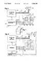
- FIG. 1is a perspective view of a physiological stimulation apparatus embodying the invention
- FIG. 2is a perspective view of the hand-held applicator thereof
- FIG. 3is a longitudinal section of the applicator
- FIG. 4is a side elevation illustrating the repositioning of the applicator head about the longitudinal axis of the first end of the applicator housing;
- FIG. 5is a plan view of the control buttons on the grasping portion of the housing
- FIG. 6is a schematic electrical diagram illustrating the electrical connections of the apparatus
- FIG. 7is a fragmentary side elevation of a modified form of head for use in the applicator.
- FIG. 8is a schematic electrical diagram illustrating a modified form of the invention wherein the applicator may be alternatively utilized as an applicator for providing electrical stimulation of the physiological tissue.
- a physiological stimulation applicatoris connected to a power source 11 by a flexible electrical conductor cable 12.
- the applicatoris adapted to be hand-held for application of physiological stimulation signals, such as ultrasound or electrical stimulation signals to the tissue of a patient.
- Applicator 10includes a watertight outer housing 13 defining a first end 14, an opposite, second end 15, and a grasping portion 16 intermediate ends 14 and 15.
- a transducer 17(see FIG. 3) is mounted within a swivel head 18 on end 14 of the housing.
- the transducercomprises a conventional crystal adapted to provide ultrasonic vibrations as a result of the application of ultrasonic high frequency electrical current thereto.
- head 18includes a distal cap 19 through which the mechanical vibrations are provided from the crystal to a patient's tissue T.
- the cap 19is formed of a suitable metal adapted to conduct high frequency electrical stimulation signals to the tissue T delivered from the power source 11.
- housing end 14defines longitudinal axis 20.
- Housing end 15defines a second longitudinal axis 21 and, in the illustrated embodiment, axis 20 extends at an angle of approximately 45° to axis 21.
- Head 18further defines a swivel connection 22 for rotatably mounting the head to housing end 14 to swivel the head about axis 20.
- the swivel headmay be selectively infinitely adjustable between a lowermost position, as shown in FIG. 3, and an uppermost position, as shown in FIG. 4, as desired by the user.
- the swivel connector 22includes a tubular insert 24 mounted in housing end 14 to project coaxially outwardly therefrom, and head 18 includes a mounting portion 25 rotatably mounted to the projecting outer portion 26 of the insert to provide a frictionally retained adjustable positioning of the head about axis 20.
- the metal cap 19is preferably grounded by a ground connection 27 to a tubular connector 28 in electrical conductive association with the cap, as shown in FIG. 3.
- a ground connection 27to a tubular connector 28 in electrical conductive association with the cap, as shown in FIG. 3.
- Switch controls generally designated 29are mounted to the housing 10 within grasping portion 16, as shown in FIG. 3.
- the switch control means 29includes a plurality of switches 30 adapted to be operated by fingertip engagement by the user's fingers, with selected ones of switch areas 31 provided on a graphic overlay 32 on the housing, as seen in FIG. 2.
- Cable 12includes a switch cable 33 connected between the switch 32 and the power source 11. Cable 12 further includes a second power-conducting cable 34 connected between the tubular connector 28 and power source 11. Cable 2 may be secured to housing end 15 by a strain relief 35 rotatively mounted in a sleeve 38 disposed coaxially in the housing. Rotation and water tightness of the strain relief is controlled by an O-ring 37 and is limited by a stop 36, as shown in FIG. 3. Cable 33 is electrically connected to the leads 39 of switches 30 by a suitable connector 40. Thus, cable 34 is free to turn about its longitudinal axis when the head 18 is angularly positioned to prevent undesirable stressing of the cable.
- Grasping portion 16 of the housingdefines a generally C-shaped housing portion having one leg 41 thereof inclined in a first direction to access 21, and an opposite, second leg 42 inclined at an opposite angle to the axis.
- the C-shaped grasping portiondefines a fingertip receiving space 43 adjacent the housing end 14 for facilitated manual positioning of the applicator head against the patient's tissue, without interference from the user's fingers grasping the applicator.
- switches 30are disposed in the first leg 41 of the grasping portion, and the housing is provided with a plurality of ribs 44 oppositely of the switches and graphic display 32 on the housing portion 41 for slip-free retention of the user's fingers in the use of the applicator.
- the usermay operate switches 30 by suitable depression of selected areas of the graphic display, while retaining the applicator firmly grasped by the embracing of the user's hand about the applicator housing portion 41.
- the userhas positive control of the applicator in pressing the head 18 against the patient's tissue.
- the positive retention of the applicatorpermits facilitated swiveling of the head to a desired angular position relative to axis 20, while firmly holding the housing portion 41 with one hand while adjusting the head.
- Cable 34may be brought outwardly through sleeve insert 24 which, as shown in FIG. 3, may have clearance with the cables.
- the sleeveis coaxially rotatable in the housing end and locked against axial displacement from the housing end 14 by a set screw 45 cooperating with an annular groove 46 in the sleeve.
- the electrical conductors 47 of cable 38are brought through the mounting portion 45 of the head to the transducer 17 and ground connection 27 for facilitated swivelling of the head about the axis 20, while maintaining the electrical connections.
- An indicator 58may be provided in the graphic display and, in the illustrated embodiment, comprises a light-emitting diode indicator at the front end of the graphic display adjacent the switch areas 31, as shown in FIG. 5.
- the indicatormay be connected to the power source to indicate when the power source is energized.
- other indicatorsmay be used in conjunction with the control, as desired.
- the selective energization of the transducer or cap for providing ultrasonic mechanical vibration physiological effects in the patient's tissue or electrical stimulation thereofmay be effected by any suitable form of power supply and control means mounted in the grasping portion of the housing within the broad scope of the invention.
- the controlincludes four switches 49, 50, 51, and 52, operated one each by the switch actuation portions 31 of the overlay 32.
- each of switches 49, 50, 51, and 52comprises a normally open switch connected to the power supply by a common lead 53 and control leads 54, 55, 56, and 57, respectively.
- LED 58is connected to the power supply by leads 59 and 60.
- a selector switch 61may be provided on the power supply for selective use of the apparatus as a mechanical vibration applicator or an electro-stimulation applicator.
- the control provided by switches 49 and 50may be selectively utilized to energize the power supply to provide suitable electrical signals for effecting operation of the transducer crystal 17 to provide ultrasonic vibration of the patient's tissue, or to provide high frequency electrical signals to the cap 19 to provide electrical stimulation of the patient's tissue.
- switches 49 and 50are connected so as to provide different power levels of the signal from the power supply to the applicator head, and switches 51 and 52 are arranged to control the power supply to provide preselected discrete different frequencies.
- the switch 49causes an increase in the power level
- switch 50controls a decrease in the power level so as to provide an infinite adjustability of the power to the applicator head.
- the frequency control meansmay similarly comprise means for providing an infinite adjustability of the frequency of the signal provided to the applicator head.
- the switchesare connected through cable 12 to a conventional microprocessor controller 62 of the power source 11.
- processor controllersare well-known to those skilled in the art and require no further description herein.
- the power sourcefurther includes an RF amplifier and oscillator of conventional construction, generally designated 63.
- RF amplifiers and oscillatorsare similarly well-known to those skilled in the art and require no further elaboration herein.
- the power cable 34is connected between the amplifier oscillator portion 63 of the power source and the applicator head and, as shown in FIG. 6, the ground portion of the cable is connected at 64 to the cap of the applicator head.
- the amplifier oscillatoris connected, in addition, through the cable 34 to the crystal transducer 17.
- both the power level and frequency characteristics of the mechanical vibrations produced by transducer 17is effected by the user's hand grasping the applicator grasping portion and urging the applicator head against the patient's tissue.
- the swivel mounting of the applicator head to the housing end 14permits facilitated application of the physiological signals to the tissue by permitting facilitated facial engagement of the planar outer surface 65 of the cap 19 against the patient's tissue
- the grasping portiondefines a fingertip receiving space 43 preventing interference between the user's hand and the tissue so as to permit facilitated facial engagement of the applicator with the tissue.
- the facilitated adjustment of the parameters of the applied physiological stimulationpermits continuous adjustment thereof when desired in directing the treatment to different portions along the surface of the tissue.
- the provision of the frictional fingertip contact means 44assures a positive control of the retention of the applicator during the use thereof to permit precise control of the physiological treatment application.
- the applicatoris extremely light in weight for further facilitated application of the physiological treatment vibrations or oscillations.
- the power sourceincludes an electrostimulation amplifier 66.
- Suitable electrodes 67may be applied to the user's skin and connected to the electrostimulation amplifier by a conductor 68.
- the conductor 69 of the cablemay be connected to the ground connection 64, whereby suitable electrical stimulation of the tissue may be effected by conduction through the tissue between electrodes 67 and ground connection 64 placed in electrical conduction engagement with the patient's tissue through the cap 19.
- Switch 61may be selectively positioned to provide for mechanical vibration use of the transducer or electrostimulation use of the cap under the control of the switches 29 carried by the housing grasping portion in the use of the apparatus.
- the inventioncomprehends that the light-emitting diode 58 may be utilized to indicate the actual coupling of the ultrasonic signal to the patient's tissue by suitable means in the power source.
- suitable meansin the power source.
- Such indicating signal meansare well-known to those skilled in the art and require no further description herein.
- the physical construction of the head of the applicatormay be varied as desired to provide a wide range of applications for the apparatus.
- a reduced diameter head 69may be utilized in lieu of the relatively large diameter swivel head 18 illustrated in FIGS. 2 and 3.
- the inventionbroadly comprehends the provision of a hand-held applicator having variable control elements in a grasping portion thereof for selectively providing physiological stimulation signals to a patient's tissue under the control of the user by fingertip manipulation of the control means in the applicator grasping portion.
- the inventioncomprehends the provision of such an applicator for use in providing different forms of physiological stimulation to a patient's tissue.
- the inventionfurther comprehends the provision of means for facilitating facial engagement of the applicator head with the patient's tissue by providing a swivelling mounting of the head to the end of the applicator housing.
Landscapes
- Health & Medical Sciences (AREA)
- Life Sciences & Earth Sciences (AREA)
- Animal Behavior & Ethology (AREA)
- Veterinary Medicine (AREA)
- Public Health (AREA)
- General Health & Medical Sciences (AREA)
- Rehabilitation Therapy (AREA)
- Physical Education & Sports Medicine (AREA)
- Pain & Pain Management (AREA)
- Epidemiology (AREA)
- Biophysics (AREA)
- Heart & Thoracic Surgery (AREA)
- Engineering & Computer Science (AREA)
- Biomedical Technology (AREA)
- Nuclear Medicine, Radiotherapy & Molecular Imaging (AREA)
- Radiology & Medical Imaging (AREA)
- Percussion Or Vibration Massage (AREA)
Abstract
Description
Claims (29)
Priority Applications (1)
| Application Number | Priority Date | Filing Date | Title |
|---|---|---|---|
| US07/206,440US5086788A (en) | 1988-06-13 | 1988-06-13 | Hand-held physiological stimulation applicator |
Applications Claiming Priority (1)
| Application Number | Priority Date | Filing Date | Title |
|---|---|---|---|
| US07/206,440US5086788A (en) | 1988-06-13 | 1988-06-13 | Hand-held physiological stimulation applicator |
Publications (1)
| Publication Number | Publication Date |
|---|---|
| US5086788Atrue US5086788A (en) | 1992-02-11 |
Family
ID=22766391
Family Applications (1)
| Application Number | Title | Priority Date | Filing Date |
|---|---|---|---|
| US07/206,440Expired - LifetimeUS5086788A (en) | 1988-06-13 | 1988-06-13 | Hand-held physiological stimulation applicator |
Country Status (1)
| Country | Link |
|---|---|
| US (1) | US5086788A (en) |
Cited By (51)
| Publication number | Priority date | Publication date | Assignee | Title |
|---|---|---|---|---|
| WO1994028853A1 (en)* | 1993-06-14 | 1994-12-22 | Satelec S.A. | Hand-held massaging and cleaning apparatus using ultrasonic vibration |
| US5413550A (en)* | 1993-07-21 | 1995-05-09 | Pti, Inc. | Ultrasound therapy system with automatic dose control |
| US5569166A (en)* | 1991-11-27 | 1996-10-29 | Stone; Ross G. | Headache tension reliever |
| DE19624163A1 (en)* | 1996-06-18 | 1998-01-29 | Gestron Versand Gmbh Medizin U | Ultrasonic therapy system |
| US5800503A (en)* | 1996-05-17 | 1998-09-01 | Swak Ventures, Inc. | Apparatus and method for producing electrical stimulation in response to an audio signal |
| US5840048A (en)* | 1995-12-22 | 1998-11-24 | Jun Sui Kan Sei Cosmetics International Limited | Skin brush massage method |
| US6007502A (en)* | 1998-03-23 | 1999-12-28 | Worldra Co., Ltd. | Ion facial massage system |
| US6132392A (en)* | 1991-11-27 | 2000-10-17 | Stone; Ross G. | Tension headache reliever with multiple pain relieving modalities |
| US6176840B1 (en)* | 1997-08-11 | 2001-01-23 | Matsushita Electric Works, Ltd. | Ultrasonic cosmetic treatment device |
| USD447811S1 (en) | 2001-01-03 | 2001-09-11 | Emjoi, Inc. | Pain relief device |
| FR2811524A1 (en)* | 2000-07-13 | 2002-01-18 | Biomedical Europ | Anti-ageing skin treatment apparatus has micro-controller connected to at least two tools - scrub and ultrasound and micro-current probe |
| EP1234566A1 (en)* | 2001-02-23 | 2002-08-28 | Matsushita Electric Works, Ltd. | Ultrasonic cosmetic treatment device |
| US6443915B1 (en)* | 1998-12-07 | 2002-09-03 | Hyun-Bae Hwang | Control device and method of portable skin beautifying apparatus |
| WO2002094375A1 (en)* | 2001-03-29 | 2002-11-28 | Sobet Ag | Hand-held device for pain relief |
| EP1338263A3 (en)* | 2002-02-23 | 2004-02-04 | Hwajin Cosmetics Co., Ltd. | Total skin management system and method using the same |
| EP1383576A4 (en)* | 2001-04-02 | 2005-11-30 | Nexmed Holdings Inc | Electrical stimulation apparatus and method |
| US20060106325A1 (en)* | 2002-10-28 | 2006-05-18 | John Perrier | Ultrasonic medical device |
| US20060200219A1 (en)* | 2005-03-01 | 2006-09-07 | Ndi Medical, Llc | Systems and methods for differentiating and/or identifying tissue regions innervated by targeted nerves for diagnostic and/or therapeutic purposes |
| US20060200207A1 (en)* | 2005-03-01 | 2006-09-07 | Ndi Medical, Llc | Systems and methods for intra-operative stimulation |
| US20070191915A1 (en)* | 2005-03-01 | 2007-08-16 | Ndi Medical, Inc. | Systems and methods for intra-operative stimulation |
| WO2007100190A1 (en)* | 2006-02-28 | 2007-09-07 | Yong Gyu Jun | An applicator for treating skin and the method for treating skin using the same |
| US20080139972A1 (en)* | 2002-10-28 | 2008-06-12 | John Perrier | Ultrasonic medical device |
| EP1944000A1 (en)* | 2007-01-15 | 2008-07-16 | Matsushita Electric Works, Ltd. | Skin care device |
| CN100428922C (en)* | 2001-05-28 | 2008-10-29 | 松下电工株式会社 | Ultrasonic beauty device |
| AU2003269595B2 (en)* | 2002-10-28 | 2008-12-18 | Perrier, John Dominic | Ultrasonic medical device |
| US20090054980A1 (en)* | 2006-03-30 | 2009-02-26 | The Government Of The U.S, As Represented By The Secretary,Department Of Health And Human Services | Device for Volitional Swallowing with a Substitute Sensory System |
| US7559945B2 (en) | 2006-01-13 | 2009-07-14 | Clarimedix Inc. | Multi-spectral photon therapy device and methods of use |
| US20090187124A1 (en)* | 2005-07-01 | 2009-07-23 | The Government Of The Usa, As Represented By The Secretary, Dept. Of Health & Human Services | Systems and methods for recovery from motor control via stimulation to a substituted site to an affected area |
| US20090204034A1 (en)* | 2008-02-07 | 2009-08-13 | May Clifford B | Apparatus and Method for Administering Pain Relief |
| US20100063423A1 (en)* | 2006-12-19 | 2010-03-11 | Cedars-Sinai Medical Center | Ultrasonic bath to increase tissue perfusion |
| US20100121196A1 (en)* | 1996-06-28 | 2010-05-13 | Sonosite, Inc. | Ultrasonic Signal Processor for a Hand Held Ultrasonic Diagnostic Instrument |
| US20110054346A1 (en)* | 2005-03-01 | 2011-03-03 | Checkpoint Surgical, Llc | Systems and methods for Intra-operative semi-quantitative threshold neural response testing related applications |
| US20110060238A1 (en)* | 2005-03-01 | 2011-03-10 | Checkpoint Surgical, Llc | Systems and methods for intra-operative physiological functional stimulation |
| US20110060243A1 (en)* | 2005-03-01 | 2011-03-10 | Checkpoint Surgical, Llc | Systems and methods for intra-operative regional neural stimulation |
| US20110060242A1 (en)* | 2005-03-01 | 2011-03-10 | Checkpoint Surgical, Llc | Systems and methods for intra-operative stimulation within a surgical field |
| ITTA20100007A1 (en)* | 2010-04-12 | 2011-10-13 | Emma Soldano | HANDPIECE FOR THE AESTHETIC TREATMENT OF THE SKIN BY COMBINED ACTION OF ULTRASOUND AND ELECTROPORATION. |
| US8443811B1 (en)* | 2002-02-27 | 2013-05-21 | CAMS Medical Instruments, Inc. | Therapy tools and treatment methods |
| US8579839B2 (en) | 2005-07-01 | 2013-11-12 | The United States Of America, As Represented By The Secretary, Department Of Health And Human Services | Methods for recovery from motor control via stimulation to a substituted site to an affected area |
| US20130310905A1 (en)* | 2002-02-27 | 2013-11-21 | CAMS Medical Instruments, Inc. | Personal Tuner with Biosensor and Bioscanner |
| USD695399S1 (en)* | 2011-08-26 | 2013-12-10 | Infuse AS Ltd. | Skin treatment applicator |
| USD732679S1 (en)* | 2013-02-28 | 2015-06-23 | Syneron Medical Ltd. | Applicator for an apparatus for skin treatment |
| USD733310S1 (en)* | 2013-02-28 | 2015-06-30 | Syneron Medical Ltd. | Applicator for an apparatus for skin treatment |
| US20170209246A1 (en)* | 2016-01-25 | 2017-07-27 | Water Pik, Inc. | Swivel assembly for oral irrigator handle |
| US20180140401A1 (en)* | 2016-11-18 | 2018-05-24 | Panasonic Intellectual Property Management Co., Ltd. | Oral cavity washing device |
| CN108066025A (en)* | 2016-11-18 | 2018-05-25 | 松下知识产权经营株式会社 | Oral cleaning device |
| US9987185B1 (en) | 2002-02-27 | 2018-06-05 | CAMS Medical Instruments, Inc. | Transducer devices, apparatus, systems and methods of operation |
| US10154792B2 (en) | 2005-03-01 | 2018-12-18 | Checkpoint Surgical, Inc. | Stimulation device adapter |
| US11213376B2 (en) | 2016-01-25 | 2022-01-04 | Water Pik, Inc. | Reduced form factor oral irrigator |
| US11229576B2 (en) | 2019-04-19 | 2022-01-25 | Passy-Muir, Inc. | Vibratory nerve exciter |
| US20220096857A1 (en)* | 2019-01-11 | 2022-03-31 | Synergotron, D.O.O. | Device for Non-Invasive Treatment of Diseases and Conditions of Living Organisms |
| US11344471B2 (en) | 2013-03-13 | 2022-05-31 | Passy-Muir, Inc. | Systems and methods for stimulating swallowing |
Citations (16)
| Publication number | Priority date | Publication date | Assignee | Title |
|---|---|---|---|---|
| US2838672A (en)* | 1954-06-29 | 1958-06-10 | Physical Medicine Products Co | Electro-therapy generator |
| GB881837A (en)* | 1957-01-31 | 1961-11-08 | Mark E Degroff | Electro-sonic apparatus |
| US3219029A (en)* | 1963-03-25 | 1965-11-23 | Groff De | Remote control medical therapy instrument |
| US3374784A (en)* | 1966-01-07 | 1968-03-26 | George T. Brent | Mechanical massage apparatus with crank and slide |
| US3841306A (en)* | 1972-10-25 | 1974-10-15 | Univ Iowa State Res Found Inc | Implantable, non-contacting nerve stimulating transducer |
| US4112923A (en)* | 1976-08-24 | 1978-09-12 | Tomecek Jerry J | Antonomic transcutaneous affect device |
| US4197851A (en)* | 1977-04-14 | 1980-04-15 | Fellus Victor M | Apparatus for emitting high-frequency electromagnetic waves |
| US4232678A (en)* | 1977-05-16 | 1980-11-11 | Joseph Skovajsa | Device for the local treatment of a patient, and more particularly applicable in acupuncture and auriculotheraphy |
| US4315503A (en)* | 1976-11-17 | 1982-02-16 | Electro-Biology, Inc. | Modification of the growth, repair and maintenance behavior of living tissues and cells by a specific and selective change in electrical environment |
| US4431000A (en)* | 1978-11-29 | 1984-02-14 | Gatron Corporation | Transcutaneous nerve stimulator with pseusorandom pulse generator |
| US4453547A (en)* | 1981-04-06 | 1984-06-12 | Physio Technology, Inc. | T-Wave inhibiting system |
| US4532938A (en)* | 1983-05-04 | 1985-08-06 | Theratronics, Inc. | Electrotherapy apparatus |
| US4535777A (en)* | 1981-08-20 | 1985-08-20 | Physio Technology, Inc. | Method of providing electrical stimulation of tissue |
| US4587957A (en)* | 1981-08-20 | 1986-05-13 | Physio Technology, Inc. | Tissue and bone regeneration |
| US4690141A (en)* | 1985-09-16 | 1987-09-01 | Castel John C | Fresnel lens light applicator |
| US4722326A (en)* | 1985-11-04 | 1988-02-02 | Ruderian Max J | Vibratory therapeutic device |
- 1988
- 1988-06-13USUS07/206,440patent/US5086788A/ennot_activeExpired - Lifetime
Patent Citations (16)
| Publication number | Priority date | Publication date | Assignee | Title |
|---|---|---|---|---|
| US2838672A (en)* | 1954-06-29 | 1958-06-10 | Physical Medicine Products Co | Electro-therapy generator |
| GB881837A (en)* | 1957-01-31 | 1961-11-08 | Mark E Degroff | Electro-sonic apparatus |
| US3219029A (en)* | 1963-03-25 | 1965-11-23 | Groff De | Remote control medical therapy instrument |
| US3374784A (en)* | 1966-01-07 | 1968-03-26 | George T. Brent | Mechanical massage apparatus with crank and slide |
| US3841306A (en)* | 1972-10-25 | 1974-10-15 | Univ Iowa State Res Found Inc | Implantable, non-contacting nerve stimulating transducer |
| US4112923A (en)* | 1976-08-24 | 1978-09-12 | Tomecek Jerry J | Antonomic transcutaneous affect device |
| US4315503A (en)* | 1976-11-17 | 1982-02-16 | Electro-Biology, Inc. | Modification of the growth, repair and maintenance behavior of living tissues and cells by a specific and selective change in electrical environment |
| US4197851A (en)* | 1977-04-14 | 1980-04-15 | Fellus Victor M | Apparatus for emitting high-frequency electromagnetic waves |
| US4232678A (en)* | 1977-05-16 | 1980-11-11 | Joseph Skovajsa | Device for the local treatment of a patient, and more particularly applicable in acupuncture and auriculotheraphy |
| US4431000A (en)* | 1978-11-29 | 1984-02-14 | Gatron Corporation | Transcutaneous nerve stimulator with pseusorandom pulse generator |
| US4453547A (en)* | 1981-04-06 | 1984-06-12 | Physio Technology, Inc. | T-Wave inhibiting system |
| US4535777A (en)* | 1981-08-20 | 1985-08-20 | Physio Technology, Inc. | Method of providing electrical stimulation of tissue |
| US4587957A (en)* | 1981-08-20 | 1986-05-13 | Physio Technology, Inc. | Tissue and bone regeneration |
| US4532938A (en)* | 1983-05-04 | 1985-08-06 | Theratronics, Inc. | Electrotherapy apparatus |
| US4690141A (en)* | 1985-09-16 | 1987-09-01 | Castel John C | Fresnel lens light applicator |
| US4722326A (en)* | 1985-11-04 | 1988-02-02 | Ruderian Max J | Vibratory therapeutic device |
Cited By (83)
| Publication number | Priority date | Publication date | Assignee | Title |
|---|---|---|---|---|
| US5569166A (en)* | 1991-11-27 | 1996-10-29 | Stone; Ross G. | Headache tension reliever |
| US6132392A (en)* | 1991-11-27 | 2000-10-17 | Stone; Ross G. | Tension headache reliever with multiple pain relieving modalities |
| WO1994028853A1 (en)* | 1993-06-14 | 1994-12-22 | Satelec S.A. | Hand-held massaging and cleaning apparatus using ultrasonic vibration |
| FR2706293A1 (en)* | 1993-06-14 | 1994-12-23 | Satelec Sa | Portable massage and cleaning machine with ultrasonic vibration. |
| US5413550A (en)* | 1993-07-21 | 1995-05-09 | Pti, Inc. | Ultrasound therapy system with automatic dose control |
| US5840048A (en)* | 1995-12-22 | 1998-11-24 | Jun Sui Kan Sei Cosmetics International Limited | Skin brush massage method |
| US5800503A (en)* | 1996-05-17 | 1998-09-01 | Swak Ventures, Inc. | Apparatus and method for producing electrical stimulation in response to an audio signal |
| DE19624163A1 (en)* | 1996-06-18 | 1998-01-29 | Gestron Versand Gmbh Medizin U | Ultrasonic therapy system |
| US8216146B2 (en)* | 1996-06-28 | 2012-07-10 | Sonosite, Inc. | Ultrasonic signal processor for a hand held ultrasonic diagnostic instrument |
| US20100121196A1 (en)* | 1996-06-28 | 2010-05-13 | Sonosite, Inc. | Ultrasonic Signal Processor for a Hand Held Ultrasonic Diagnostic Instrument |
| US6176840B1 (en)* | 1997-08-11 | 2001-01-23 | Matsushita Electric Works, Ltd. | Ultrasonic cosmetic treatment device |
| US6007502A (en)* | 1998-03-23 | 1999-12-28 | Worldra Co., Ltd. | Ion facial massage system |
| US6443915B1 (en)* | 1998-12-07 | 2002-09-03 | Hyun-Bae Hwang | Control device and method of portable skin beautifying apparatus |
| FR2811524A1 (en)* | 2000-07-13 | 2002-01-18 | Biomedical Europ | Anti-ageing skin treatment apparatus has micro-controller connected to at least two tools - scrub and ultrasound and micro-current probe |
| USD447811S1 (en) | 2001-01-03 | 2001-09-11 | Emjoi, Inc. | Pain relief device |
| US20020120218A1 (en)* | 2001-02-23 | 2002-08-29 | Matsushita Electric Works, Ltd. | Ultrasonic cosmetic treatment device |
| EP1234566A1 (en)* | 2001-02-23 | 2002-08-28 | Matsushita Electric Works, Ltd. | Ultrasonic cosmetic treatment device |
| WO2002094375A1 (en)* | 2001-03-29 | 2002-11-28 | Sobet Ag | Hand-held device for pain relief |
| AT6199U3 (en)* | 2001-03-29 | 2005-08-25 | Sobet Ag | HAND DEVICE FOR PAIN REDUCTION |
| EP1383576A4 (en)* | 2001-04-02 | 2005-11-30 | Nexmed Holdings Inc | Electrical stimulation apparatus and method |
| CN100428922C (en)* | 2001-05-28 | 2008-10-29 | 松下电工株式会社 | Ultrasonic beauty device |
| EP1338263A3 (en)* | 2002-02-23 | 2004-02-04 | Hwajin Cosmetics Co., Ltd. | Total skin management system and method using the same |
| US9233261B1 (en)* | 2002-02-27 | 2016-01-12 | CAMS Medical Instruments, Inc. | Therapy apparatus and treatment methods |
| US20130310905A1 (en)* | 2002-02-27 | 2013-11-21 | CAMS Medical Instruments, Inc. | Personal Tuner with Biosensor and Bioscanner |
| US8443811B1 (en)* | 2002-02-27 | 2013-05-21 | CAMS Medical Instruments, Inc. | Therapy tools and treatment methods |
| US9463332B2 (en)* | 2002-02-27 | 2016-10-11 | CAMS Medical Instruments, Inc. | Personal tuner with biosensor and bioscanner |
| US9987185B1 (en) | 2002-02-27 | 2018-06-05 | CAMS Medical Instruments, Inc. | Transducer devices, apparatus, systems and methods of operation |
| US20080139972A1 (en)* | 2002-10-28 | 2008-06-12 | John Perrier | Ultrasonic medical device |
| AU2003269595B2 (en)* | 2002-10-28 | 2008-12-18 | Perrier, John Dominic | Ultrasonic medical device |
| US7909782B2 (en)* | 2002-10-28 | 2011-03-22 | John Perrier | Ultrasonic medical device |
| US20060106325A1 (en)* | 2002-10-28 | 2006-05-18 | John Perrier | Ultrasonic medical device |
| EP1560629A4 (en)* | 2002-10-28 | 2010-07-14 | John Perrier | Ultrasonic medical device |
| US20110060243A1 (en)* | 2005-03-01 | 2011-03-10 | Checkpoint Surgical, Llc | Systems and methods for intra-operative regional neural stimulation |
| US10154792B2 (en) | 2005-03-01 | 2018-12-18 | Checkpoint Surgical, Inc. | Stimulation device adapter |
| US11576599B2 (en) | 2005-03-01 | 2023-02-14 | Checkpoint Surgical, Llc | Stimulation device adapter |
| US20070191915A1 (en)* | 2005-03-01 | 2007-08-16 | Ndi Medical, Inc. | Systems and methods for intra-operative stimulation |
| US7878981B2 (en) | 2005-03-01 | 2011-02-01 | Checkpoint Surgical, Llc | Systems and methods for intra-operative stimulation |
| US7896815B2 (en) | 2005-03-01 | 2011-03-01 | Checkpoint Surgical, Llc | Systems and methods for intra-operative stimulation |
| US20110054346A1 (en)* | 2005-03-01 | 2011-03-03 | Checkpoint Surgical, Llc | Systems and methods for Intra-operative semi-quantitative threshold neural response testing related applications |
| US20110060238A1 (en)* | 2005-03-01 | 2011-03-10 | Checkpoint Surgical, Llc | Systems and methods for intra-operative physiological functional stimulation |
| US20060200207A1 (en)* | 2005-03-01 | 2006-09-07 | Ndi Medical, Llc | Systems and methods for intra-operative stimulation |
| US20110060242A1 (en)* | 2005-03-01 | 2011-03-10 | Checkpoint Surgical, Llc | Systems and methods for intra-operative stimulation within a surgical field |
| US20060200219A1 (en)* | 2005-03-01 | 2006-09-07 | Ndi Medical, Llc | Systems and methods for differentiating and/or identifying tissue regions innervated by targeted nerves for diagnostic and/or therapeutic purposes |
| US10470678B2 (en) | 2005-03-01 | 2019-11-12 | Checkpoint Surgical, Inc. | Systems and methods for intra-operative stimulation |
| US8388561B2 (en) | 2005-07-01 | 2013-03-05 | The United States Of America, As Represented By The Secretary, Department Of Health And Human Services | Systems and methods for recovery from motor control via stimulation to a substituted site to an affected area |
| US8579839B2 (en) | 2005-07-01 | 2013-11-12 | The United States Of America, As Represented By The Secretary, Department Of Health And Human Services | Methods for recovery from motor control via stimulation to a substituted site to an affected area |
| US10071016B2 (en) | 2005-07-01 | 2018-09-11 | The United States Of America, As Represented By The Secretary, Department Of Health And Human Services | Systems for recovery from motor control via stimulation to a substituted site to an affected area |
| US20090187124A1 (en)* | 2005-07-01 | 2009-07-23 | The Government Of The Usa, As Represented By The Secretary, Dept. Of Health & Human Services | Systems and methods for recovery from motor control via stimulation to a substituted site to an affected area |
| US7559945B2 (en) | 2006-01-13 | 2009-07-14 | Clarimedix Inc. | Multi-spectral photon therapy device and methods of use |
| KR100799524B1 (en)* | 2006-02-28 | 2008-01-31 | 전용규 | Applicator of Skin Care Device |
| WO2007100190A1 (en)* | 2006-02-28 | 2007-09-07 | Yong Gyu Jun | An applicator for treating skin and the method for treating skin using the same |
| US8449445B2 (en)* | 2006-03-30 | 2013-05-28 | The United States Of America, As Represented By The Secretary, Department Of Health And Human Services | Device for volitional swallowing with a substitute sensory system |
| US20090054980A1 (en)* | 2006-03-30 | 2009-02-26 | The Government Of The U.S, As Represented By The Secretary,Department Of Health And Human Services | Device for Volitional Swallowing with a Substitute Sensory System |
| US8852074B2 (en) | 2006-03-30 | 2014-10-07 | The United States Of America, As Represented By The Secretary, Department Of Health And Human Services | Device for volitional swallowing with a substitute sensory system |
| US20100063423A1 (en)* | 2006-12-19 | 2010-03-11 | Cedars-Sinai Medical Center | Ultrasonic bath to increase tissue perfusion |
| US9050448B2 (en)* | 2006-12-19 | 2015-06-09 | Cedars-Sinai Medical Center | Ultrasonic bath to increase tissue perfusion |
| EP1944000A1 (en)* | 2007-01-15 | 2008-07-16 | Matsushita Electric Works, Ltd. | Skin care device |
| US9216136B2 (en) | 2008-02-07 | 2015-12-22 | Clifford B. May | Apparatus and method for administering pain relief |
| US20090204034A1 (en)* | 2008-02-07 | 2009-08-13 | May Clifford B | Apparatus and Method for Administering Pain Relief |
| US8808207B2 (en) | 2008-09-16 | 2014-08-19 | The United States Of America, As Represented By The Secretary, Department Of Health And Human Services | Systems and methods for recovery from motor control via stimulation to a substituted site to an affected area |
| ITTA20100007A1 (en)* | 2010-04-12 | 2011-10-13 | Emma Soldano | HANDPIECE FOR THE AESTHETIC TREATMENT OF THE SKIN BY COMBINED ACTION OF ULTRASOUND AND ELECTROPORATION. |
| USD695400S1 (en)* | 2011-08-26 | 2013-12-10 | Infuse AS Ltd. | Skin treatment applicator |
| USD695399S1 (en)* | 2011-08-26 | 2013-12-10 | Infuse AS Ltd. | Skin treatment applicator |
| USD732679S1 (en)* | 2013-02-28 | 2015-06-23 | Syneron Medical Ltd. | Applicator for an apparatus for skin treatment |
| USD733310S1 (en)* | 2013-02-28 | 2015-06-30 | Syneron Medical Ltd. | Applicator for an apparatus for skin treatment |
| US11344471B2 (en) | 2013-03-13 | 2022-05-31 | Passy-Muir, Inc. | Systems and methods for stimulating swallowing |
| US11850203B2 (en) | 2013-03-13 | 2023-12-26 | Passy-Muir, Inc. | Systems and methods for stimulating swallowing |
| US11642203B2 (en) | 2016-01-25 | 2023-05-09 | Water Pik, Inc. | Oral irrigator handle with hose connector fittings |
| US20170209246A1 (en)* | 2016-01-25 | 2017-07-27 | Water Pik, Inc. | Swivel assembly for oral irrigator handle |
| US12207983B2 (en) | 2016-01-25 | 2025-01-28 | Water Pik, Inc. | Oral irrigator handle with hose connector fittings |
| US12186147B2 (en) | 2016-01-25 | 2025-01-07 | Water Pik, Inc. | Reduced form factor oral irrigator |
| US10835356B2 (en)* | 2016-01-25 | 2020-11-17 | Water Pik, Inc. | Swivel assembly for oral irrigator handle |
| US11213376B2 (en) | 2016-01-25 | 2022-01-04 | Water Pik, Inc. | Reduced form factor oral irrigator |
| US11432918B2 (en)* | 2016-11-18 | 2022-09-06 | Panasonic Intellectual Property Management Co., Ltd. | Oral cavity washing device |
| CN108066025A (en)* | 2016-11-18 | 2018-05-25 | 松下知识产权经营株式会社 | Oral cleaning device |
| US20180140401A1 (en)* | 2016-11-18 | 2018-05-24 | Panasonic Intellectual Property Management Co., Ltd. | Oral cavity washing device |
| US20220096857A1 (en)* | 2019-01-11 | 2022-03-31 | Synergotron, D.O.O. | Device for Non-Invasive Treatment of Diseases and Conditions of Living Organisms |
| US11419784B2 (en) | 2019-04-19 | 2022-08-23 | Passy-Muir, Inc. | Vibratory nerve exciter |
| US11413214B2 (en) | 2019-04-19 | 2022-08-16 | Passy-Muir, Inc. | Methods of vibrationally exciting a laryngeal nerve |
| US11850205B2 (en) | 2019-04-19 | 2023-12-26 | Passy-Muir, Inc. | Methods of vibrationally exciting a laryngeal nerve |
| US11229576B2 (en) | 2019-04-19 | 2022-01-25 | Passy-Muir, Inc. | Vibratory nerve exciter |
| US12220373B2 (en) | 2019-04-19 | 2025-02-11 | Passy-Muir, Inc. | Systems for vibrationally exciting a laryngeal nerve |
| US12220374B2 (en) | 2019-04-19 | 2025-02-11 | Passy-Muir, Inc. | Methods and systems for vibrationally exciting a laryngeal nerve |
Similar Documents
| Publication | Publication Date | Title |
|---|---|---|
| US5086788A (en) | Hand-held physiological stimulation applicator | |
| US5989248A (en) | Medical device and methods for treating tissues | |
| US7244257B2 (en) | Electrosurgical pencil having a single button variable control | |
| US6165206A (en) | Apparatus for medical ablation use and methods thereof | |
| US7828794B2 (en) | Handheld electrosurgical apparatus for controlling operating room equipment | |
| CA2869728C (en) | Vaginal remodeling device and method | |
| US6206842B1 (en) | Ultrasonic operation device | |
| US5860976A (en) | Electrosurgical cutting device | |
| US6249706B1 (en) | Electrotherapy system | |
| US6050993A (en) | Medical device and methods for treating hemorrhoids | |
| EP0696928B1 (en) | Bipolar electrosurgical trocar | |
| US6562032B1 (en) | Electrosurgical instrument with vibration | |
| US4962766A (en) | Nerve locator and stimulator | |
| US6059781A (en) | Electroconvergent cautery system | |
| US20190209234A1 (en) | Radio frequency handpiece for medical treatments | |
| US5922012A (en) | Low-frequency electrotherapeutic device having three or more electrodes for generating flexible stimulation patterns | |
| US5741250A (en) | Electrosurgical instrument for ear surgery | |
| JP5067992B2 (en) | Surgical equipment | |
| KR20200122339A (en) | Ultrasonic device for mechanically applying ultrasonic waves effectively | |
| US20180147416A1 (en) | Method and System for Appetite Suppression by Laser Stimulation of Acupuncture Points | |
| KR101828849B1 (en) | Tinnitus treatment system using knife needle | |
| JPH0489068A (en) | High-frequency cosmetic device | |
| JPH031029B2 (en) | ||
| KR20010028769A (en) | a low energy laser theraphy system and method for controling the same | |
| KR102745019B1 (en) | Rf energy generator capable of controlling the penetration depth of energy |
Legal Events
| Date | Code | Title | Description |
|---|---|---|---|
| AS | Assignment | Owner name:K.D.F., A KS NOMINEE PARTNERSHIP AND REIMER AND KO Free format text:SECURITY INTEREST;ASSIGNOR:PHYSIO TECHNOLOGY, INC.;REEL/FRAME:005008/0687 Effective date:19881223 | |
| FEPP | Fee payment procedure | Free format text:PAYOR NUMBER ASSIGNED (ORIGINAL EVENT CODE: ASPN); ENTITY STATUS OF PATENT OWNER: SMALL ENTITY | |
| STCF | Information on status: patent grant | Free format text:PATENTED CASE | |
| FPAY | Fee payment | Year of fee payment:4 | |
| FEPP | Fee payment procedure | Free format text:PAYER NUMBER DE-ASSIGNED (ORIGINAL EVENT CODE: RMPN); ENTITY STATUS OF PATENT OWNER: SMALL ENTITY Free format text:PAYOR NUMBER ASSIGNED (ORIGINAL EVENT CODE: ASPN); ENTITY STATUS OF PATENT OWNER: SMALL ENTITY | |
| FPAY | Fee payment | Year of fee payment:8 | |
| REMI | Maintenance fee reminder mailed | ||
| REIN | Reinstatement after maintenance fee payment confirmed | ||
| FP | Lapsed due to failure to pay maintenance fee | Effective date:20040211 | |
| FEPP | Fee payment procedure | Free format text:PETITION RELATED TO MAINTENANCE FEES FILED (ORIGINAL EVENT CODE: PMFP); ENTITY STATUS OF PATENT OWNER: SMALL ENTITY | |
| FEPP | Fee payment procedure | Free format text:PETITION RELATED TO MAINTENANCE FEES GRANTED (ORIGINAL EVENT CODE: PMFG); ENTITY STATUS OF PATENT OWNER: SMALL ENTITY | |
| AS | Assignment | Owner name:PTI, INC., KANSAS Free format text:CHANGE OF NAME;ASSIGNOR:PHYSIO TECHNOLOGY, INC.;REEL/FRAME:016164/0001 Effective date:19940715 Owner name:HC INC., KANSAS Free format text:NUNC PRO TUNC ASSIGNMENT;ASSIGNOR:PTI INC.;REEL/FRAME:016164/0025 Effective date:19970205 Owner name:SUNDANCE REHABILITATION CORPORATION, NEW MEXICO Free format text:ASSIGNMENT OF ASSIGNORS INTEREST;ASSIGNOR:HC INC.;REEL/FRAME:016164/0072 Effective date:19970403 | |
| AS | Assignment | Owner name:ACCELERATED CARE PLUS CORP., NEVADA Free format text:ASSIGNMENT OF ASSIGNORS INTEREST;ASSIGNORS:CASTEL, JOHN C.;BEACH, JOHN B.;BEACH, CURTIS;REEL/FRAME:016145/0788 Effective date:20010501 Owner name:CASTEL, JOHN C., NEVADA Free format text:ASSIGNMENT OF ASSIGNORS INTEREST;ASSIGNOR:SUNDANCE REHABILITATION CORPORATION;REEL/FRAME:016145/0781 Effective date:20000731 Owner name:BEACH, JOHN B., NEVADA Free format text:ASSIGNMENT OF ASSIGNORS INTEREST;ASSIGNOR:SUNDANCE REHABILITATION CORPORATION;REEL/FRAME:016145/0781 Effective date:20000731 Owner name:BEACH, CURTIS, NEVADA Free format text:ASSIGNMENT OF ASSIGNORS INTEREST;ASSIGNOR:SUNDANCE REHABILITATION CORPORATION;REEL/FRAME:016145/0781 Effective date:20000731 | |
| FPAY | Fee payment | Year of fee payment:12 | |
| SULP | Surcharge for late payment | ||
| PRDP | Patent reinstated due to the acceptance of a late maintenance fee | Effective date:20050919 |