US5086783A - Blood sampling device - Google Patents
Blood sampling deviceDownload PDFInfo
- Publication number
- US5086783A US5086783AUS07/607,410US60741090AUS5086783AUS 5086783 AUS5086783 AUS 5086783AUS 60741090 AUS60741090 AUS 60741090AUS 5086783 AUS5086783 AUS 5086783A
- Authority
- US
- United States
- Prior art keywords
- proximal
- distal
- assembly
- distal end
- needle
- Prior art date
- Legal status (The legal status is an assumption and is not a legal conclusion. Google has not performed a legal analysis and makes no representation as to the accuracy of the status listed.)
- Expired - Lifetime
Links
- 238000010241blood samplingMethods0.000titleclaimsabstract21
- 239000008280bloodSubstances0.000claimsabstractdescription160
- 210000004369bloodAnatomy0.000claimsabstractdescription160
- 238000013022ventingMethods0.000claimsabstractdescription16
- 238000000034methodMethods0.000claimsabstractdescription5
- 239000000463materialSubstances0.000claimsdescription12
- 230000000717retained effectEffects0.000claimsdescription5
- 210000004204blood vesselAnatomy0.000claimsdescription4
- 238000003780insertionMethods0.000claims1
- 230000037431insertionEffects0.000claims1
- 239000007789gasSubstances0.000description42
- 210000001367arteryAnatomy0.000description6
- 230000003466anti-cipated effectEffects0.000description3
- 210000003462veinAnatomy0.000description3
- CURLTUGMZLYLDI-UHFFFAOYSA-NCarbon dioxideChemical compoundO=C=OCURLTUGMZLYLDI-UHFFFAOYSA-N0.000description2
- 230000004872arterial blood pressureEffects0.000description2
- 229920001971elastomerPolymers0.000description2
- 230000007246mechanismEffects0.000description2
- 206010053567CoagulopathiesDiseases0.000description1
- HTTJABKRGRZYRN-UHFFFAOYSA-NHeparinChemical compoundOC1C(NC(=O)C)C(O)OC(COS(O)(=O)=O)C1OC1C(OS(O)(=O)=O)C(O)C(OC2C(C(OS(O)(=O)=O)C(OC3C(C(O)C(O)C(O3)C(O)=O)OS(O)(=O)=O)C(CO)O2)NS(O)(=O)=O)C(C(O)=O)O1HTTJABKRGRZYRN-UHFFFAOYSA-N0.000description1
- 239000004743PolypropyleneSubstances0.000description1
- 239000003146anticoagulant agentSubstances0.000description1
- 229940127219anticoagulant drugDrugs0.000description1
- 238000013459approachMethods0.000description1
- QVGXLLKOCUKJST-UHFFFAOYSA-Natomic oxygenChemical compound[O]QVGXLLKOCUKJST-UHFFFAOYSA-N0.000description1
- 229910002092carbon dioxideInorganic materials0.000description1
- 239000001569carbon dioxideSubstances0.000description1
- 230000035602clottingEffects0.000description1
- 239000013065commercial productSubstances0.000description1
- 239000000356contaminantSubstances0.000description1
- 229960002897heparinDrugs0.000description1
- 229920000669heparinPolymers0.000description1
- 239000004816latexSubstances0.000description1
- 229920000126latexPolymers0.000description1
- 238000005259measurementMethods0.000description1
- 229910052760oxygenInorganic materials0.000description1
- 239000001301oxygenSubstances0.000description1
- 239000004033plasticSubstances0.000description1
- -1polypropylenePolymers0.000description1
- 229920001155polypropylenePolymers0.000description1
- 238000012552reviewMethods0.000description1
- 239000003566sealing materialSubstances0.000description1
- 230000035939shockEffects0.000description1
Images

Classifications
- A—HUMAN NECESSITIES
- A61—MEDICAL OR VETERINARY SCIENCE; HYGIENE
- A61M—DEVICES FOR INTRODUCING MEDIA INTO, OR ONTO, THE BODY; DEVICES FOR TRANSDUCING BODY MEDIA OR FOR TAKING MEDIA FROM THE BODY; DEVICES FOR PRODUCING OR ENDING SLEEP OR STUPOR
- A61M5/00—Devices for bringing media into the body in a subcutaneous, intra-vascular or intramuscular way; Accessories therefor, e.g. filling or cleaning devices, arm-rests
- A61M5/178—Syringes
- A61M5/31—Details
- A61M5/315—Pistons; Piston-rods; Guiding, blocking or restricting the movement of the rod or piston; Appliances on the rod for facilitating dosing ; Dosing mechanisms
- A61M5/31511—Piston or piston-rod constructions, e.g. connection of piston with piston-rod
- A—HUMAN NECESSITIES
- A61—MEDICAL OR VETERINARY SCIENCE; HYGIENE
- A61B—DIAGNOSIS; SURGERY; IDENTIFICATION
- A61B5/00—Measuring for diagnostic purposes; Identification of persons
- A61B5/15—Devices for taking samples of blood
- A61B5/150007—Details
- A61B5/150015—Source of blood
- A61B5/15003—Source of blood for venous or arterial blood
- A—HUMAN NECESSITIES
- A61—MEDICAL OR VETERINARY SCIENCE; HYGIENE
- A61B—DIAGNOSIS; SURGERY; IDENTIFICATION
- A61B5/00—Measuring for diagnostic purposes; Identification of persons
- A61B5/15—Devices for taking samples of blood
- A61B5/150007—Details
- A61B5/150206—Construction or design features not otherwise provided for; manufacturing or production; packages; sterilisation of piercing element, piercing device or sampling device
- A61B5/150213—Venting means
- A—HUMAN NECESSITIES
- A61—MEDICAL OR VETERINARY SCIENCE; HYGIENE
- A61B—DIAGNOSIS; SURGERY; IDENTIFICATION
- A61B5/00—Measuring for diagnostic purposes; Identification of persons
- A61B5/15—Devices for taking samples of blood
- A61B5/150007—Details
- A61B5/150206—Construction or design features not otherwise provided for; manufacturing or production; packages; sterilisation of piercing element, piercing device or sampling device
- A61B5/150236—Pistons, i.e. cylindrical bodies that sit inside the syringe barrel, typically with an air tight seal, and slide in the barrel to create a vacuum or to expel blood
- A—HUMAN NECESSITIES
- A61—MEDICAL OR VETERINARY SCIENCE; HYGIENE
- A61B—DIAGNOSIS; SURGERY; IDENTIFICATION
- A61B5/00—Measuring for diagnostic purposes; Identification of persons
- A61B5/15—Devices for taking samples of blood
- A61B5/150007—Details
- A61B5/150206—Construction or design features not otherwise provided for; manufacturing or production; packages; sterilisation of piercing element, piercing device or sampling device
- A61B5/150244—Rods for actuating or driving the piston, i.e. the cylindrical body that sits inside the syringe barrel, typically with an air tight seal, and slides in the barrel to create a vacuum or to expel blood
- A—HUMAN NECESSITIES
- A61—MEDICAL OR VETERINARY SCIENCE; HYGIENE
- A61B—DIAGNOSIS; SURGERY; IDENTIFICATION
- A61B5/00—Measuring for diagnostic purposes; Identification of persons
- A61B5/15—Devices for taking samples of blood
- A61B5/150007—Details
- A61B5/150351—Caps, stoppers or lids for sealing or closing a blood collection vessel or container, e.g. a test-tube or syringe barrel
- A—HUMAN NECESSITIES
- A61—MEDICAL OR VETERINARY SCIENCE; HYGIENE
- A61B—DIAGNOSIS; SURGERY; IDENTIFICATION
- A61B5/00—Measuring for diagnostic purposes; Identification of persons
- A61B5/15—Devices for taking samples of blood
- A61B5/150007—Details
- A61B5/150374—Details of piercing elements or protective means for preventing accidental injuries by such piercing elements
- A61B5/150381—Design of piercing elements
- A61B5/150389—Hollow piercing elements, e.g. canulas, needles, for piercing the skin
- A—HUMAN NECESSITIES
- A61—MEDICAL OR VETERINARY SCIENCE; HYGIENE
- A61B—DIAGNOSIS; SURGERY; IDENTIFICATION
- A61B5/00—Measuring for diagnostic purposes; Identification of persons
- A61B5/15—Devices for taking samples of blood
- A61B5/150007—Details
- A61B5/150374—Details of piercing elements or protective means for preventing accidental injuries by such piercing elements
- A61B5/150381—Design of piercing elements
- A61B5/150473—Double-ended needles, e.g. used with pre-evacuated sampling tubes
- A61B5/150496—Details of construction of hub, i.e. element used to attach the double-ended needle to a piercing device or sampling device
- A—HUMAN NECESSITIES
- A61—MEDICAL OR VETERINARY SCIENCE; HYGIENE
- A61B—DIAGNOSIS; SURGERY; IDENTIFICATION
- A61B5/00—Measuring for diagnostic purposes; Identification of persons
- A61B5/15—Devices for taking samples of blood
- A61B5/153—Devices specially adapted for taking samples of venous or arterial blood, e.g. with syringes
- A—HUMAN NECESSITIES
- A61—MEDICAL OR VETERINARY SCIENCE; HYGIENE
- A61B—DIAGNOSIS; SURGERY; IDENTIFICATION
- A61B5/00—Measuring for diagnostic purposes; Identification of persons
- A61B5/15—Devices for taking samples of blood
- A61B5/150007—Details
- A61B5/150206—Construction or design features not otherwise provided for; manufacturing or production; packages; sterilisation of piercing element, piercing device or sampling device
- A61B5/150259—Improved gripping, e.g. with high friction pattern or projections on the housing surface or an ergonometric shape
- A—HUMAN NECESSITIES
- A61—MEDICAL OR VETERINARY SCIENCE; HYGIENE
- A61B—DIAGNOSIS; SURGERY; IDENTIFICATION
- A61B5/00—Measuring for diagnostic purposes; Identification of persons
- A61B5/15—Devices for taking samples of blood
- A61B5/153—Devices specially adapted for taking samples of venous or arterial blood, e.g. with syringes
- A61B5/154—Devices using pre-evacuated means
Definitions
- the present inventionrelates to a medical device which includes a stopper assembly for use with an arterial blood gas syringe and blood collection tube holder and needle to obtain blood sample from a patient.
- Blood samplesare commonly obtained from a patient using either an arterial blood gas syringe for obtaining arterial blood samples from a patient or by using a vacuum blood collection tube and blood collection tube holder for obtaining venous blood samples from a patient.
- Arterial blood gas syringestypically include a syringe barrel, a standard needle and a plunger rod with a piston member on the distal end thereof.
- the piston member and/or the plunger rodinclude a venting structure to prevent oxygen or carbon dioxide from reacting with the arterial blood sample so that an accurate measurement of the components of the blood sample may be performed.
- FIG. 1Another approach to obtaining a blood sample from a patient is illustrated in U.S. Pat. No. 4,192,320 granted to Megahed.
- the Megahed patentdiscloses the use of an adaptor for use with a conventional syringe assembly and a conventional blood collection tube holder to obtain a blood sample from the vein of the patient.
- the adaptoris described as being of a conventional elastomeric, self-sealing material which is frictionally retained on the distal end of the conventional syringe assembly. Once the adaptor has been placed on the distal end of the conventional syringe assembly, this combination is inserted into a blood collection tube holder which has previously been inserted into the vein of the patient.
- the adaptor and syringe assemblyare then inserted into the blood collection tube holder until the proximal end of the double ended needle on the blood collection tube holder pierces the adaptor.
- the blood sampleis then obtained from the vein of the patient by a combination of the patient's venous pressure plus the retraction of the plunger of the syringe assembly to aspirate the blood into the syringe chamber. Once a sufficient venous blood sample has been obtained, the adaptor and syringe assembly are removed from the blood collection tube holder and the collected venous blood sample is then analyzed.
- One object of the present inventionis to provide a stopper assembly having a needle piercable diaphragm member therein to prevent exposure of the blood sample to atmospheric air once it has been collected.
- Another object of the present inventionis to provide a stopper assembly which will assist in aligning the distal end of the syringe with the proximal end of the double ended needle on the blood collection tube holder.
- a further object of the present inventionis to provide an improved method for obtaining an arterial blood sample from a patient.
- one form of the present inventionincludes a stopper assembly which is designed to be frictionally retained on the distal end of an arterial blood gas syringe to enable the assembly to be inserted into a blood collection tube holder.
- the stopper assemblyconsists of a two-piece housing having a diaphragm member centrally positioned therebetween.
- the preferred arterial blood gas syringeis a commercial product known as the MARZ-175 sold by Sherwood Medical Company, St. Louis, Mo., U.S.A. which is disclosed and more fully described in U.S. Pat. No. 4,615,341 granted to Marzolf et al.
- the blood collection tube holderconsists of an elongate tubular member having an open proximal end with a plurality of finger flanges extending therefrom and a reduced diameter distal end having a double ended needle thereon.
- the distal portion of the double ended needle on the blood collection tube holderis inserted into the artery of the patient.
- the plunger of the arterial blood gas syringeis then withdrawn to a predetermined position in the syringe barrel to form a sample chamber having the desired volume.
- the proximal section of the stopper assembly housingis then attached to the tapered distal luer portion of the arterial blood gas syringe.
- the arterial blood gas syringe and the stopper assemblyare then inserted through the proximal end of the blood collection tube holder until the distal section of the stopper assembly housing contacts and compresses a rubber sleeve located on the proximal portion of the double ended needle.
- the proximal needle point on the double ended needlethen pierces the diaphragm member in the stopper assembly.
- the patient's arterial bloodwill then flow through the double ended needle and into the sample chamber.
- the air in the sample chamberwill be forced through the venting structure in the arterial blood gas syringe until only the arterial blood sample remains in the sample chamber.
- the arterial blood gas syringe and the stopper assemblyare removed from the blood collection tube holder.
- the blood sampleis then transported to the laboratory where the technician may either remove the stopper assembly from the arterial blood gas syringe or pierce the diaphragm member of the stopper assembly to inject the blood sample into the analyzer.
- An advantage of the present inventionis that the stopper assembly of the present invention may be used with nearly any syringe or blood collection tube holder.
- a further advantage of the present inventionis that multiple blood samples may be obtained from the patient or the arterial blood gas syringe may be replaced with a conventional syringe to aspirate the blood sample from the patient without having to repuncture the blood vessel of the patient.
- FIG. 1is an exploded perspective view of the arterial blood gas syringe, stopper assembly and blood collection tube holder and needle of the present invention
- FIG. 2is a cross-sectioned view of the stopper assembly of the present invention taken generally along lines 2--2 of FIG. 1;
- FIG. 3is a top view of the stopper assembly of the present invention.
- FIG. 4is a bottom view of the stopper assembly of the present invention.
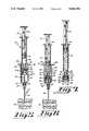
- FIG. 5is a partially cross-sectioned plan view showing the blood collection tube holder and needle of the present invention with the arterial blood gas syringe and stopper assembly partially inserted therein;
- FIG. 6is a partially cross-sectioned plan view showing the blood collection tube holder and needle of the present invention with the syringe and stopper assembly inserted therein to receive a blood sample in the sample chamber of the arterial blood gas syringe;
- FIG. 7is a partially cross-sectioned plan view showing the arterial blood gas syringe and stopper assembly of the present invention having a collected blood sample therein;
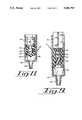
- FIG. 8is a partial cross-sectional view of the distal portion of the preferred form of the arterial blood gas syringe shown in FIG. 1;
- FIG. 9is a partial cross-sectional view of the distal portion of an alternate form of an arterial blood gas syringe which may be used with the stopper assembly of the present invention.
- the present inventionconsists generally of a stopper assembly 10, an arterial blood gas syringe 12 and a blood collection tube holder 14 and needle 16.
- the distal end of a partis the end of the part designed to be positioned closest to the patient.
- the proximal end of a partis the end of the part designed to be positioned away from the patient.
- the stopper assembly 10 of the present inventionincludes a proximal housing section 18 and a distal housing section 20, both of which are preferably constructed of a semi-rigid plastic such as polypropylene.
- the proximal housing section 18 and the distal housing section 20are preferably ultrasonically welded or otherwise bonded together to retain an air impervious and needle piercable diaphragm member 22 therebetween.
- the diaphragm member 22is a generally circularly-shaped member which is preferably constructed of flexible material such as latex.
- the generally cylindrical proximal housing section 18includes a central opening 24 extending lengthwise therethrough.
- the proximal portion of the proximal housing section 18includes a first section 26 with the preferred inner diameter of the central opening 24 being approximately 4.5 mm and with an inward taper of approximately 6°.
- the preferred outer diameter of the first section 26is approximately 6.8 mm and extends proximally approximately 6.8 mm from the distally positioned second section 28.
- the second section 28 of the proximal housing section 18includes a plurality of evenly spaced and longitudinally aligned positioning ribs 30 extending radially outwardly from the circumference of the second section 28.
- the preferred outer diameter of the second section 28is approximately 11.8 mm as measured from the outer surface of the positioning ribs 30.
- the diameter of the central opening 24 in the second section 28is sized to receive a portion of the distal housing section 20 therein and has a preferred diameter of approximately 7.5 mm.
- the preferred length of the proximal housing section 18is approximately 12 mm and the preferred length of the assembled stopper assembly 10 is approximately 19 mm.
- the generally cylindrical distal housing section 20includes a central opening 32 extending therethrough.
- the central opening 32 of the distal housing section 20preferably includes a proximal section 34 having a preferred inner diameter of approximately 4.5 mm and a distal section 36 having a preferred inner diameter of approximately 7.5 mm.
- the central opening 32may be tapered inwardly or chamfered to facilitate locating the needle 16 in the distal end of the arterial blood gas syringe 12.
- the outer surface of the distal housing section 20preferably includes a plurality of equally spaced and longitudinally extending positioning ribs 38 which extend radially outwardly and proximally from the distal end of the distal housing section 20 approximately 7 mm so that the preferred outer diameter of the distal housing section 20 is approximately 11.8 mm as measured along the positioning ribs 38.
- the proximal end of the distal housing section 20includes a proximally extending lip 40 which extends approximately 1.3 mm from proximal side of the distal housing section 20 and is sized to be received in the distal portion of the second section 28 of the proximal housing section 18 to allow the distal housing section 20 and the proximal housing section 18 to be ultrasonically welded or otherwise bonded together.
- a diaphragm member 22is fixedly retained in the stopper assembly 10 by the distal housing section 20 and the proximal housing section 18.
- the lip 40 on the distal housing section 20extends into the second section 28 a sufficient distance to retain the diaphragm member 22 therein when the distal housing section 20 and the proximal housing section 18 are ultrasonically welded or otherwise assembled to form a unitary stopper assembly 10 wherein the diaphragm member 22 separates the central opening 24 of the proximal housing section 18 and the central opening 32 of the distal housing section 20.
- the stopper assembly 10 of the present inventionis preferably designed for use with an arterial blood gas syringe 12 although it is anticipated that in certain situations as described hereinafter, a conventional syringe assembly may also be used with the present invention.
- the arterial blood gas syringe 12in describing the preferred forms of the arterial blood gas syringe 12 as shown in FIGS. 1, 8 and 9, like numbers have been applied to like elements.
- the preferred form of the arterial blood gas syringe 12 used with the present inventionhas a capacity of approximately 3 cc and a preferred outer diameter of approximately 11 mm.
- the arterial blood gas syringe 12consists generally of an elongate and tubular barrel section 42 having an open proximal end 44 and a reduced diameter distal end 46 with a gradually tapering luer extension 48 extending therefrom.
- An elongate plunger rod 50extends distally into the open proximal end 44 of the barrel section 42.
- the distal end of the plunger rod 50preferably includes an elastomeric piston 52 thereon which sealingly contacts the inner surface of the barrel section 42.
- the piston 52preferably includes at least one air passageway 54 extending therethrough.
- the air passageway 54preferably includes a venting member 56 such as a porous thread (FIG. 8) or a porous plug member (FIG. 9) extending therethrough, the function of which are described more fully hereinafter.
- the inner surface of the distal end of the barrel section 42will typically include an anticoagulant such as heparin therein to limit or prevent the clotting of the blood sample as described hereinafter.
- the blood collection tube holder 14consists generally of an elongate and cylindrically-shaped barrel section 60 which has a slight inward taper from the open proximal end 62 to the substantially closed distal end 64.
- the proximal end 62preferably includes a plurality of radially and outwardly extending finger members 66 and the distal end 64 of the blood collection tube holder 14 preferably includes an internally threaded distal extension 67 which is designed to removably receive the threaded hub 68 of the double ended needle 16 therein.
- the double ended needle 16is generally linear and includes distal and proximal needle sections, 70 and 72 respectively, which further include distal and proximal needle points thereon, 74 and 76, respectively.
- proximal needle section 72 and the proximal needle point 76are encircled by a resilient rubber sleeve member 78 which encloses the proximal needle section 72 and proximal needle point 76 prior to and after use of the present invention as described more fully hereinafter.
- Assembly and use of the present inventionis relatively simple and provides a convenient way to obtain one or more blood samples from a single puncture in the artery or blood vessel of a patient.
- the needle 16is threadedly attached to the blood collection tube holder 14 and the plunger rod 50 of the arterial blood gas syringe 12 is withdrawn to move the piston 52 proximally in the barrel section 42 of the arterial blood gas syringe 12 to form a sample chamber 80 having the desired sample volume between the piston 52 and the distal end 46 of the barrel section 42.
- the stopper assemblyis then frictionally, threadedly or otherwise attached to the luer extension 48 of the arterial blood gas syringe 12 by inserting the luer extension 48 into the central opening 24 of the proximal housing section 18 so that the luer extension 48 is retained in the first section 26 of the proximal housing section 18.
- the nurse or technicianmay insert the distal needle section 70 of the needle 16 into the patient so that the distal needle point 74 extends into the artery of the patient.
- the sleeve member 78 on the proximal needle section 72prevents the flow of blood through the needle 16 until the sleeve member 78 is compressed as described hereinafter.
- the nurse or technicianinserts the stopper assembly 10 and arterial blood gas syringe 12 combination into the proximal end 62 of the blood collection tube holder 14. Because the outer circumference of the stopper assembly 10, as measured around the positioning ribs, 30 and 38, is only slightly smaller than the inner circumference of the blood collection tube holder 14 and is larger than the outer circumference of the arterial blood gas syringe 12, the alignment of the proximal needle section 72 with the central openings 32 and 24 of the stopper assembly 10 is ensured as the stopper assembly 10 is moved distally in the blood collection tube holder 14.
- the relative size of the stopper assembly 10 with respect to the inner circumference of the blood collection tube holder 14ensures that the proximal needle section 72 of the needle will be aligned to pierce the diaphragm member 22 and enter a portion of the luer extension 48 as the stopper assembly 10 and arterial blood gas syringe 12 are inserted distally into the blood collection tube holder 14.
- the use of the positioning ribs, 30 and 38, on the stopper assembly 10allows any air that is displaced in the blood collection tube holder 14 to flow around the sides of the stopper assembly and out of the proximal end 62 of the blood collection tube holder 14.
- the proximal needle section 72is somehow misaligned with the central opening 32, the proximal needle section will be deflected to realign the needle 16 with the diaphragm member 22 in the stopper assembly 10 and the luer extension 48 of the arterial blood gas syringe 12.
- the sleeve member 78will contact the diaphragm member 22. Initially, the proximal needle point 76 will pierce the sleeve member 78. Next, as the stopper assembly 10 and arterial blood gas syringe 12 are moved further distally in the blood collection tube holder 14, the sleeve member 78 will become compressed to expose the proximal needle point 76 and the proximal needle point 76 will pierce the diaphragm member 22 and enter a portion of the luer extension 48.
- the overall length of the stopper assembly 10is chosen so that even if the piston 52 of the arterial blood gas syringe 12 is positioned at the distal end 46 of the barrel section 42, the proximal needle point 76 will not pierce the piston 52.
- the arterial blood gas syringe 12may include a variety of other venting mechanisms such as a mechanical venting mechanism allow the air to pass therethrough and to seal the sample chamber 80 once the blood sample has been obtained. As all of the air is forced out of the sample chamber 80, the blood sample will wet the venting member 56 which automatically swells or otherwise closes the air passageway 54 in the piston 52.
- the arterial blood gas syringe 12 and the stopper assembly 10may be withdrawn from the blood collection tube holder 14 as shown in FIG. 7.
- the diaphragm member 22will close and form an air-tight seal with the distal end 46 of the arterial blood gas syringe 12 and the sleeve member 78 will return to its original position to prevent the flow of blood through the needle 16. If another blood sample is desired, the foregoing steps may be repeated without the need to repuncture the artery of the patient.
- the arterial blood gas syringe 12 and the stopper assembly 10may b quickly removed from the blood collection tube holder 14 and the arterial blood gas syringe 12 may be replaced with a conventional syringe assembly (not shown).
- the pistonwill be positioned at the distal end of the syringe assembly as the stopper assembly 10 is placed on the luer extension.
- the diaphragm member 22 in the stopper assembly 10will form an air tight seal with the distal end of the syringe assembly and the sleeve member 78 will return to its original position along the proximal needle section 72 to prevent the flow of blood through the needle 16.
- the stopper assembly 10 of the present inventionis preferably used with a blood collection tube holder 14 having a double ended needle 16 which is preferably removably mounted thereon.
- the relative preferred dimensions for the blood collection tube holder 14are for a blood collection tube holder known in the medical industry as a pediatric blood collection tube holder.
- the pediatric blood collection tube holderhas in inner diameter of approximately 12 mm and is designed to receive a blood collection tube having a diameter of approximately 10.25 mm therein. It should be understood that the preferred dimensions for the stopper assembly 10 as set forth herein are for use with a pediatric sized blood collection tube holder.
- the relative dimensions of the stopper assemblywill likewise be proportionately increased so that the stopper assembly may be used with adult blood collection tube holders which are designed to receive blood collection tubes having a diameter of either 13 mm or 16 mm therein while retaining the preferred relative dimensions of the present invention wherein the outer diameter of the syringe assembly is preferably smaller than the diameter of the stopper assembly and the outer diameter of the stopper assembly is preferably smaller than the inner diameter of the blood collection tube holder.
Landscapes
- Health & Medical Sciences (AREA)
- Life Sciences & Earth Sciences (AREA)
- Engineering & Computer Science (AREA)
- Animal Behavior & Ethology (AREA)
- Hematology (AREA)
- Veterinary Medicine (AREA)
- Public Health (AREA)
- Biomedical Technology (AREA)
- Heart & Thoracic Surgery (AREA)
- General Health & Medical Sciences (AREA)
- Pathology (AREA)
- Surgery (AREA)
- Molecular Biology (AREA)
- Medical Informatics (AREA)
- Biophysics (AREA)
- Physics & Mathematics (AREA)
- Manufacturing & Machinery (AREA)
- Vascular Medicine (AREA)
- Anesthesiology (AREA)
- Measurement Of The Respiration, Hearing Ability, Form, And Blood Characteristics Of Living Organisms (AREA)
Abstract
Description
Claims (26)
Priority Applications (1)
| Application Number | Priority Date | Filing Date | Title |
|---|---|---|---|
| US07/607,410US5086783A (en) | 1990-10-31 | 1990-10-31 | Blood sampling device |
Applications Claiming Priority (1)
| Application Number | Priority Date | Filing Date | Title |
|---|---|---|---|
| US07/607,410US5086783A (en) | 1990-10-31 | 1990-10-31 | Blood sampling device |
Publications (1)
| Publication Number | Publication Date |
|---|---|
| US5086783Atrue US5086783A (en) | 1992-02-11 |
Family
ID=24432148
Family Applications (1)
| Application Number | Title | Priority Date | Filing Date |
|---|---|---|---|
| US07/607,410Expired - LifetimeUS5086783A (en) | 1990-10-31 | 1990-10-31 | Blood sampling device |
Country Status (1)
| Country | Link |
|---|---|
| US (1) | US5086783A (en) |
Cited By (26)
| Publication number | Priority date | Publication date | Assignee | Title |
|---|---|---|---|---|
| US5415626A (en)* | 1993-06-25 | 1995-05-16 | Megadyne Medical Products, Inc. | Two piece releasable bandage |
| US5474546A (en)* | 1994-05-09 | 1995-12-12 | Abbott Laboratories | Dripless cannula system usable with a sampling container for fluid sampling and operable to minimize fluid loss at a fluid sampling site |
| WO1997039676A1 (en)* | 1996-04-25 | 1997-10-30 | Sims Portex Inc. | Self-filling blood collection device |
| DE19703178A1 (en)* | 1997-01-29 | 1998-08-06 | Sarstedt Walter Geraete | Blood collection device |
| EP0903107A1 (en)* | 1997-09-09 | 1999-03-24 | Sarstedt AG & Co. | Blood sampling device |
| US6238578B1 (en)* | 1996-12-09 | 2001-05-29 | Sherwood Services Ag | Method for dispensing separator gel in a blood collection tube |
| US6264619B1 (en)* | 1999-09-01 | 2001-07-24 | Becton, Dickinson And Company | Kit for drawing a blood sample |
| US6491667B1 (en) | 1999-08-31 | 2002-12-10 | Becton, Dickinson And Company | Syringe tip cap |
| US20030236497A1 (en)* | 2002-06-25 | 2003-12-25 | Radiometer Medical A/S | Sampler cap |
| US20050267384A1 (en)* | 2004-06-01 | 2005-12-01 | Sauer Kevin P | Blood collection kit adapter |
| US20060074350A1 (en)* | 2004-10-04 | 2006-04-06 | Biosensors International Usa | Blood sampling kit and method of using same |
| US20060184157A1 (en)* | 1996-03-29 | 2006-08-17 | Spohn Michael A | Front-loading syringe adapter for front-loading medical injector |
| US20090156963A1 (en)* | 2007-12-14 | 2009-06-18 | Tyco Healthcare Group Lp | Blood Collection Device with Tube Retaining Structure |
| CN101040103B (en)* | 2004-10-18 | 2010-05-05 | Avl里斯脱有限公司 | internal combustion engine |
| US20110224611A1 (en)* | 2010-03-15 | 2011-09-15 | Becton, Dickinson And Company | Medical device including an air evacuation system |
| US20120209172A1 (en)* | 2000-08-22 | 2012-08-16 | Synthes Usa, Llc | Bone-Regeneration Material |
| US20130197477A1 (en)* | 2010-10-01 | 2013-08-01 | Sanofi-Aventis Deutschland Gmbh | Needle assembly with release mechanism |
| WO2014209686A1 (en)* | 2013-06-26 | 2014-12-31 | Becton, Dickinson And Company | Integrated closed iv line draw system |
| US9174007B2 (en) | 2010-03-15 | 2015-11-03 | Becton, Dickinson And Company | Medical device including an air evacuation system |
| WO2018130734A1 (en)* | 2017-01-12 | 2018-07-19 | Biotechnology Institute, I Mas D, S.L. | Container device for collecting, storing and processing blood or a blood compound |
| US20180220999A1 (en)* | 2017-02-07 | 2018-08-09 | New York University | Endoswab for Sampling and Culture in Minimally Invasive Surgery |
| WO2019156932A1 (en)* | 2018-02-06 | 2019-08-15 | Becton, Dickinson And Company | Biological fluid collection and stabilization system |
| KR20210057757A (en)* | 2018-09-06 | 2021-05-21 | 벡톤 디킨슨 앤드 컴퍼니 | Arterial blood gas collection system |
| US11275096B2 (en)* | 2017-09-28 | 2022-03-15 | Bioceryx Technologies Inc. | Blood transfer devices and methods thereof |
| RU2830579C2 (en)* | 2018-02-06 | 2024-11-22 | Бектон, Дикинсон Энд Компани | Biological fluid collection and stabilization system |
| WO2024197226A3 (en)* | 2023-03-23 | 2025-01-02 | Becton, Dickinson And Company | Bidirectional stopper valve that mates to a venting syringe |
Citations (11)
| Publication number | Priority date | Publication date | Assignee | Title |
|---|---|---|---|---|
| US3900028A (en)* | 1974-02-26 | 1975-08-19 | American Hospital Supply Corp | Injection site for sterile medical liquid container |
| US3931815A (en)* | 1973-08-29 | 1976-01-13 | Jintan Terumo Company, Ltd. | Assembly having an adapter and a holder with a double ended needle |
| US4192320A (en)* | 1977-07-28 | 1980-03-11 | Becton, Dickinson And Company | Adapter for syringe |
| US4378812A (en)* | 1979-12-04 | 1983-04-05 | Kunststoff-Spritzgubwerk | Devices for sampling blood |
| US4445896A (en)* | 1982-03-18 | 1984-05-01 | Cook, Inc. | Catheter plug |
| US4448206A (en)* | 1981-08-17 | 1984-05-15 | Martell Michael D | Vented, aspirating syringe |
| US4572210A (en)* | 1981-07-01 | 1986-02-25 | Marquest Medical Products, Inc. | Syringe with means for allowing passage of air while preventing the passage of blood to obtain a gas-free blood sample |
| US4615341A (en)* | 1981-06-18 | 1986-10-07 | Syringe Industries, Inc. | Syringe device for physiological fluid sampling |
| US4673396A (en)* | 1982-11-22 | 1987-06-16 | Ray Urbaniak | Syringe cartridge |
| US4774963A (en)* | 1981-05-20 | 1988-10-04 | Terumo Kabushiki Kaisha | Blood collector |
| US4856533A (en)* | 1985-01-29 | 1989-08-15 | Sekisui Kagaku Kogyo Kabushiki Kaisha | Vacuum blood-collection tube |
- 1990
- 1990-10-31USUS07/607,410patent/US5086783A/ennot_activeExpired - Lifetime
Patent Citations (11)
| Publication number | Priority date | Publication date | Assignee | Title |
|---|---|---|---|---|
| US3931815A (en)* | 1973-08-29 | 1976-01-13 | Jintan Terumo Company, Ltd. | Assembly having an adapter and a holder with a double ended needle |
| US3900028A (en)* | 1974-02-26 | 1975-08-19 | American Hospital Supply Corp | Injection site for sterile medical liquid container |
| US4192320A (en)* | 1977-07-28 | 1980-03-11 | Becton, Dickinson And Company | Adapter for syringe |
| US4378812A (en)* | 1979-12-04 | 1983-04-05 | Kunststoff-Spritzgubwerk | Devices for sampling blood |
| US4774963A (en)* | 1981-05-20 | 1988-10-04 | Terumo Kabushiki Kaisha | Blood collector |
| US4615341A (en)* | 1981-06-18 | 1986-10-07 | Syringe Industries, Inc. | Syringe device for physiological fluid sampling |
| US4572210A (en)* | 1981-07-01 | 1986-02-25 | Marquest Medical Products, Inc. | Syringe with means for allowing passage of air while preventing the passage of blood to obtain a gas-free blood sample |
| US4448206A (en)* | 1981-08-17 | 1984-05-15 | Martell Michael D | Vented, aspirating syringe |
| US4445896A (en)* | 1982-03-18 | 1984-05-01 | Cook, Inc. | Catheter plug |
| US4673396A (en)* | 1982-11-22 | 1987-06-16 | Ray Urbaniak | Syringe cartridge |
| US4856533A (en)* | 1985-01-29 | 1989-08-15 | Sekisui Kagaku Kogyo Kabushiki Kaisha | Vacuum blood-collection tube |
Cited By (54)
| Publication number | Priority date | Publication date | Assignee | Title |
|---|---|---|---|---|
| US5415626A (en)* | 1993-06-25 | 1995-05-16 | Megadyne Medical Products, Inc. | Two piece releasable bandage |
| US5474546A (en)* | 1994-05-09 | 1995-12-12 | Abbott Laboratories | Dripless cannula system usable with a sampling container for fluid sampling and operable to minimize fluid loss at a fluid sampling site |
| US20010007315A1 (en)* | 1995-12-12 | 2001-07-12 | Fiehler William R. | Method and apparatus for dispensing separator gel in a blood collection tube |
| US20060184157A1 (en)* | 1996-03-29 | 2006-08-17 | Spohn Michael A | Front-loading syringe adapter for front-loading medical injector |
| WO1997039676A1 (en)* | 1996-04-25 | 1997-10-30 | Sims Portex Inc. | Self-filling blood collection device |
| US5893834A (en)* | 1996-04-25 | 1999-04-13 | Sims Portex Inc. | Self-filling blood collection device |
| US6238578B1 (en)* | 1996-12-09 | 2001-05-29 | Sherwood Services Ag | Method for dispensing separator gel in a blood collection tube |
| DE19703178A1 (en)* | 1997-01-29 | 1998-08-06 | Sarstedt Walter Geraete | Blood collection device |
| EP0903107A1 (en)* | 1997-09-09 | 1999-03-24 | Sarstedt AG & Co. | Blood sampling device |
| US6006931A (en)* | 1997-09-09 | 1999-12-28 | Sarstedt Ag & Co. | Membrane cap for blood-sampling tube |
| USRE40428E1 (en)* | 1999-08-31 | 2008-07-08 | Becton, Dickinson And Company | Syringe Having Needle Isolation Features |
| US6491667B1 (en) | 1999-08-31 | 2002-12-10 | Becton, Dickinson And Company | Syringe tip cap |
| US6264619B1 (en)* | 1999-09-01 | 2001-07-24 | Becton, Dickinson And Company | Kit for drawing a blood sample |
| US8679072B2 (en)* | 2000-08-22 | 2014-03-25 | DePuy Synthes Products, LLC | Bone-regeneration material |
| US20120209172A1 (en)* | 2000-08-22 | 2012-08-16 | Synthes Usa, Llc | Bone-Regeneration Material |
| US20030236497A1 (en)* | 2002-06-25 | 2003-12-25 | Radiometer Medical A/S | Sampler cap |
| US7896818B2 (en)* | 2002-06-25 | 2011-03-01 | Radiometer Medical Aps | Sampler cap |
| US8444621B2 (en) | 2002-06-25 | 2013-05-21 | Radiometer Medical Aps | Sampler cap |
| US20110144593A1 (en)* | 2002-06-25 | 2011-06-16 | Radiometer Medical Aps | Sampler Cap |
| US20050267384A1 (en)* | 2004-06-01 | 2005-12-01 | Sauer Kevin P | Blood collection kit adapter |
| US20060074350A1 (en)* | 2004-10-04 | 2006-04-06 | Biosensors International Usa | Blood sampling kit and method of using same |
| US7445604B2 (en) | 2004-10-04 | 2008-11-04 | Biosensors International Usa | Blood sampling kit and method of using same |
| CN101040103B (en)* | 2004-10-18 | 2010-05-05 | Avl里斯脱有限公司 | internal combustion engine |
| US20090156963A1 (en)* | 2007-12-14 | 2009-06-18 | Tyco Healthcare Group Lp | Blood Collection Device with Tube Retaining Structure |
| US9192327B2 (en) | 2007-12-14 | 2015-11-24 | Covidien Lp | Blood collection device with tube retaining structure |
| US8172794B2 (en) | 2010-03-15 | 2012-05-08 | Becton, Dickinson And Company | Medical device including an air evacuation system |
| US8172795B2 (en)* | 2010-03-15 | 2012-05-08 | Becton, Dickinson And Company | Medical device including an air evacuation system |
| US20110224612A1 (en)* | 2010-03-15 | 2011-09-15 | Becton, Dickinson And Company | Medical device including an air evacuation system |
| US11679203B2 (en) | 2010-03-15 | 2023-06-20 | Becton, Dickinson And Company | Medical device including an air evacuation system |
| US9174007B2 (en) | 2010-03-15 | 2015-11-03 | Becton, Dickinson And Company | Medical device including an air evacuation system |
| US20110224611A1 (en)* | 2010-03-15 | 2011-09-15 | Becton, Dickinson And Company | Medical device including an air evacuation system |
| US10898650B2 (en) | 2010-03-15 | 2021-01-26 | Becton, Dickinson And Company | Medical device including an air evacuation system |
| US10173011B2 (en) | 2010-03-15 | 2019-01-08 | Becton, Dickinson And Company | Medical device including an air evacuation system |
| US20130197477A1 (en)* | 2010-10-01 | 2013-08-01 | Sanofi-Aventis Deutschland Gmbh | Needle assembly with release mechanism |
| US8864740B2 (en)* | 2010-10-01 | 2014-10-21 | Sanofi-Aventis Deutschland Gmbh | Needle assembly with release mechanism |
| AU2014302966B2 (en)* | 2013-06-26 | 2018-09-13 | Becton, Dickinson And Company | Integrated closed IV line draw system |
| US9839385B2 (en) | 2013-06-26 | 2017-12-12 | Becton, Dickinson And Company | Integrated closed IV line draw system |
| WO2014209686A1 (en)* | 2013-06-26 | 2014-12-31 | Becton, Dickinson And Company | Integrated closed iv line draw system |
| WO2018130734A1 (en)* | 2017-01-12 | 2018-07-19 | Biotechnology Institute, I Mas D, S.L. | Container device for collecting, storing and processing blood or a blood compound |
| US10912539B2 (en)* | 2017-02-07 | 2021-02-09 | New York University | Endoswab for sampling and culture in minimally invasive surgery |
| US20180220999A1 (en)* | 2017-02-07 | 2018-08-09 | New York University | Endoswab for Sampling and Culture in Minimally Invasive Surgery |
| US11275096B2 (en)* | 2017-09-28 | 2022-03-15 | Bioceryx Technologies Inc. | Blood transfer devices and methods thereof |
| US11540756B2 (en) | 2018-02-06 | 2023-01-03 | Becton, Dickinson And Company | Biological fluid collection and stabilization system |
| RU2752601C1 (en)* | 2018-02-06 | 2021-07-29 | Бектон, Дикинсон Энд Компани | Biological fluid collection and stabilisation system |
| JP2022000663A (en)* | 2018-02-06 | 2022-01-04 | ベクトン・ディキンソン・アンド・カンパニーBecton, Dickinson And Company | Biological fluid collection and stabilization system |
| JP2021513074A (en)* | 2018-02-06 | 2021-05-20 | ベクトン・ディキンソン・アンド・カンパニーBecton, Dickinson And Company | Biofluid collection and stabilization system |
| JP7233502B2 (en) | 2018-02-06 | 2023-03-06 | ベクトン・ディキンソン・アンド・カンパニー | Biofluid collection and stabilization system |
| WO2019156932A1 (en)* | 2018-02-06 | 2019-08-15 | Becton, Dickinson And Company | Biological fluid collection and stabilization system |
| EP4275602A1 (en)* | 2018-02-06 | 2023-11-15 | Becton, Dickinson and Company | Biological fluid collection and stabilization system |
| RU2830579C2 (en)* | 2018-02-06 | 2024-11-22 | Бектон, Дикинсон Энд Компани | Biological fluid collection and stabilization system |
| KR20210057757A (en)* | 2018-09-06 | 2021-05-21 | 벡톤 디킨슨 앤드 컴퍼니 | Arterial blood gas collection system |
| KR102827944B1 (en) | 2018-09-06 | 2025-07-02 | 벡톤 디킨슨 앤드 컴퍼니 | Arterial blood gas collection system |
| US12433520B2 (en) | 2018-09-06 | 2025-10-07 | Becton, Dickinson And Company | Arterial blood gas collection system |
| WO2024197226A3 (en)* | 2023-03-23 | 2025-01-02 | Becton, Dickinson And Company | Bidirectional stopper valve that mates to a venting syringe |
Similar Documents
| Publication | Publication Date | Title |
|---|---|---|
| US5086783A (en) | Blood sampling device | |
| US11291393B2 (en) | Medical device for collection of a biological sample | |
| US5653243A (en) | Fluid sample collection and introduction device and method | |
| US5360011A (en) | Blood sample collection | |
| US7351228B2 (en) | Plunger rod for arterial blood collection syringes | |
| US4572210A (en) | Syringe with means for allowing passage of air while preventing the passage of blood to obtain a gas-free blood sample | |
| EP2986216B1 (en) | Medical device for collection of a biological sample | |
| KR101133652B1 (en) | Flashback Blood Collection Needle | |
| US4393882A (en) | Method and device for collecting, transporting, and delivering micro samples of blood | |
| US5947932A (en) | Closed system blood sampling device | |
| US6755802B2 (en) | Whole blood sampling device | |
| US3943917A (en) | Method for collecting blood samples | |
| US6155991A (en) | Apparatus and method for collecting blood samples | |
| US20100049231A1 (en) | Lancet Removal Tool | |
| GB2176710A (en) | Arterial blood sampler | |
| JPS6355933B2 (en) | ||
| US6902534B2 (en) | Method and kit of components for delivering blood to a portable clinical analyzer | |
| US4821738A (en) | Arterial blood gas syringe | |
| US4245655A (en) | Blood collection device | |
| CN103957794B (en) | blood collection components | |
| IE46528B1 (en) | Improvements in and relating to assemblies for collecting blood or other fluids | |
| WO2024197226A2 (en) | Bidirectional stopper valve that mates to a venting syringe | |
| JPS6215212B2 (en) |
Legal Events
| Date | Code | Title | Description |
|---|---|---|---|
| AS | Assignment | Owner name:SHERWOOD MEDICAL NEDERLAND B.V., 5201 AL'S-HERTOGE Free format text:ASSIGNMENT OF ASSIGNORS INTEREST.;ASSIGNORS:PAULUSSEN, HENRICUS F.;VOS, JELLARD;REEL/FRAME:005535/0773 Effective date:19901123 Owner name:SHERWOOD MEDICAL S.A., PARC INDUSTRIEL DE PETIT-RE Free format text:ASSIGNMENT OF ASSIGNORS INTEREST.;ASSIGNOR:SHERWOOD MEDICAL S.A.;REEL/FRAME:005535/0767 Effective date:19901107 Owner name:SHERWOOD MEDICAL COMPANY, 1831 OLIVE STREET, ST. L Free format text:ASSIGNMENT OF ASSIGNORS INTEREST.;ASSIGNOR:SHERWOOD MEDICAL S.A.;REEL/FRAME:005535/0769 Effective date:19901030 Owner name:SHERWOOD MEDICAL COMPANY, 1831 OLIVE STREET, ST. L Free format text:ASSIGNMENT OF ASSIGNORS INTEREST.;ASSIGNOR:SHERWOOD MEDICAL NEDERLAND B.V.;REEL/FRAME:005535/0771 Effective date:19901030 | |
| STCF | Information on status: patent grant | Free format text:PATENTED CASE | |
| FEPP | Fee payment procedure | Free format text:PAYOR NUMBER ASSIGNED (ORIGINAL EVENT CODE: ASPN); ENTITY STATUS OF PATENT OWNER: LARGE ENTITY | |
| FPAY | Fee payment | Year of fee payment:4 | |
| FPAY | Fee payment | Year of fee payment:8 | |
| AS | Assignment | Owner name:SHERWOOD SERVICES AG, SWITZERLAND Free format text:ASSIGNMENT OF ASSIGNORS INTEREST;ASSIGNOR:TYCO GROUP S.A.R.L.;REEL/FRAME:010180/0294 Effective date:19990406 Owner name:TYCO GROUP S.A.R.L., LUXEMBOURG Free format text:ASSIGNMENT OF ASSIGNORS INTEREST;ASSIGNOR:SHERWOOD MEDICAL COMPANY;REEL/FRAME:010255/0446 Effective date:19990406 | |
| FPAY | Fee payment | Year of fee payment:12 |