US5085658A - Neurosurgical pathological tissue removing device - Google Patents
Neurosurgical pathological tissue removing deviceDownload PDFInfo
- Publication number
- US5085658A US5085658AUS07/403,185US40318589AUS5085658AUS 5085658 AUS5085658 AUS 5085658AUS 40318589 AUS40318589 AUS 40318589AUS 5085658 AUS5085658 AUS 5085658A
- Authority
- US
- United States
- Prior art keywords
- resecting
- disposed
- tube
- central nervous
- nervous system
- Prior art date
- Legal status (The legal status is an assumption and is not a legal conclusion. Google has not performed a legal analysis and makes no representation as to the accuracy of the status listed.)
- Expired - Lifetime
Links
- 230000001575pathological effectEffects0.000titleclaimsabstractdescription35
- 210000003169central nervous systemAnatomy0.000claimsabstractdescription40
- 230000000740bleeding effectEffects0.000claimsabstractdescription5
- 229910052751metalInorganic materials0.000claimsdescription18
- 239000002184metalSubstances0.000claimsdescription18
- 239000013307optical fiberSubstances0.000claimsdescription17
- 239000012530fluidSubstances0.000claimsdescription8
- 238000005286illuminationMethods0.000claimsdescription7
- 230000001427coherent effectEffects0.000claimsdescription6
- 230000002093peripheral effectEffects0.000claimsdescription6
- 239000011810insulating materialSubstances0.000claimsdescription3
- 238000001228spectrumMethods0.000claimsdescription3
- 238000006243chemical reactionMethods0.000claimsdescription2
- 210000000653nervous systemAnatomy0.000claims1
- 238000000034methodMethods0.000abstractdescription26
- 230000008569processEffects0.000abstractdescription22
- 230000000007visual effectEffects0.000abstractdescription8
- 238000012800visualizationMethods0.000abstractdescription6
- 210000001519tissueAnatomy0.000description78
- 230000007246mechanismEffects0.000description28
- 238000001356surgical procedureMethods0.000description14
- 239000006163transport mediaSubstances0.000description13
- 230000002572peristaltic effectEffects0.000description8
- 210000003625skullAnatomy0.000description8
- 239000000126substanceSubstances0.000description7
- 239000007788liquidSubstances0.000description6
- 238000002271resectionMethods0.000description6
- 230000003902lesionEffects0.000description5
- 238000001959radiotherapyMethods0.000description5
- 208000002193PainDiseases0.000description4
- 230000004888barrier functionEffects0.000description4
- 210000003128headAnatomy0.000description4
- 230000003287optical effectEffects0.000description4
- 210000004761scalpAnatomy0.000description4
- 206010028980NeoplasmDiseases0.000description3
- FAPWRFPIFSIZLT-UHFFFAOYSA-MSodium chlorideChemical compound[Na+].[Cl-]FAPWRFPIFSIZLT-UHFFFAOYSA-M0.000description3
- 230000002159abnormal effectEffects0.000description3
- 210000004556brainAnatomy0.000description3
- 201000010099diseaseDiseases0.000description3
- 208000037265diseases, disorders, signs and symptomsDiseases0.000description3
- 239000000835fiberSubstances0.000description3
- 238000003780insertionMethods0.000description3
- 230000037431insertionEffects0.000description3
- 239000002609mediumSubstances0.000description3
- 238000011084recoveryMethods0.000description3
- 239000011780sodium chlorideSubstances0.000description3
- XKRFYHLGVUSROY-UHFFFAOYSA-NArgonChemical compound[Ar]XKRFYHLGVUSROY-UHFFFAOYSA-N0.000description2
- CURLTUGMZLYLDI-UHFFFAOYSA-NCarbon dioxideChemical compoundO=C=OCURLTUGMZLYLDI-UHFFFAOYSA-N0.000description2
- 208000006735PeriostitisDiseases0.000description2
- 238000013461designMethods0.000description2
- 230000000694effectsEffects0.000description2
- 238000001839endoscopyMethods0.000description2
- 230000036541healthEffects0.000description2
- 230000002262irrigationEffects0.000description2
- 238000003973irrigationMethods0.000description2
- 230000007170pathologyEffects0.000description2
- 210000003460periosteumAnatomy0.000description2
- 208000003174Brain NeoplasmsDiseases0.000description1
- 229910052691ErbiumInorganic materials0.000description1
- 229910052779NeodymiumInorganic materials0.000description1
- 208000004550Postoperative PainDiseases0.000description1
- 208000002847Surgical WoundDiseases0.000description1
- 210000003423ankleAnatomy0.000description1
- 229910052786argonInorganic materials0.000description1
- 230000005540biological transmissionEffects0.000description1
- 238000001574biopsyMethods0.000description1
- 239000008280bloodSubstances0.000description1
- 210000004369bloodAnatomy0.000description1
- 201000011510cancerDiseases0.000description1
- 229910002092carbon dioxideInorganic materials0.000description1
- 239000001569carbon dioxideSubstances0.000description1
- 239000003795chemical substances by applicationSubstances0.000description1
- 238000001816coolingMethods0.000description1
- 208000012106cystic neoplasmDiseases0.000description1
- 238000003745diagnosisMethods0.000description1
- 238000009297electrocoagulationMethods0.000description1
- UYAHIZSMUZPPFV-UHFFFAOYSA-NerbiumChemical compound[Er]UYAHIZSMUZPPFV-UHFFFAOYSA-N0.000description1
- 210000005095gastrointestinal systemAnatomy0.000description1
- 238000002682general surgeryMethods0.000description1
- 239000011521glassSubstances0.000description1
- 230000023597hemostasisEffects0.000description1
- 238000012977invasive surgical procedureMethods0.000description1
- 210000003127kneeAnatomy0.000description1
- 239000000463materialSubstances0.000description1
- QEFYFXOXNSNQGX-UHFFFAOYSA-Nneodymium atomChemical compound[Nd]QEFYFXOXNSNQGX-UHFFFAOYSA-N0.000description1
- 238000002355open surgical procedureMethods0.000description1
- 230000037361pathwayEffects0.000description1
- 230000005855radiationEffects0.000description1
- 230000005810radionecrosisEffects0.000description1
- 239000010979rubySubstances0.000description1
- 229910001750rubyInorganic materials0.000description1
- 229910052594sapphireInorganic materials0.000description1
- 239000010980sapphireSubstances0.000description1
- 210000002832shoulderAnatomy0.000description1
- 239000000779smokeSubstances0.000description1
- 230000002269spontaneous effectEffects0.000description1
- 238000012549trainingMethods0.000description1
- 230000002485urinary effectEffects0.000description1
- 210000002229urogenital systemAnatomy0.000description1
- 210000000707wristAnatomy0.000description1
Images


Classifications
- A—HUMAN NECESSITIES
- A61—MEDICAL OR VETERINARY SCIENCE; HYGIENE
- A61B—DIAGNOSIS; SURGERY; IDENTIFICATION
- A61B18/00—Surgical instruments, devices or methods for transferring non-mechanical forms of energy to or from the body
- A61B18/18—Surgical instruments, devices or methods for transferring non-mechanical forms of energy to or from the body by applying electromagnetic radiation, e.g. microwaves
- A61B18/20—Surgical instruments, devices or methods for transferring non-mechanical forms of energy to or from the body by applying electromagnetic radiation, e.g. microwaves using laser
- A61B18/22—Surgical instruments, devices or methods for transferring non-mechanical forms of energy to or from the body by applying electromagnetic radiation, e.g. microwaves using laser the beam being directed along or through a flexible conduit, e.g. an optical fibre; Couplings or hand-pieces therefor
- A61B18/24—Surgical instruments, devices or methods for transferring non-mechanical forms of energy to or from the body by applying electromagnetic radiation, e.g. microwaves using laser the beam being directed along or through a flexible conduit, e.g. an optical fibre; Couplings or hand-pieces therefor with a catheter
- A—HUMAN NECESSITIES
- A61—MEDICAL OR VETERINARY SCIENCE; HYGIENE
- A61B—DIAGNOSIS; SURGERY; IDENTIFICATION
- A61B1/00—Instruments for performing medical examinations of the interior of cavities or tubes of the body by visual or photographical inspection, e.g. endoscopes; Illuminating arrangements therefor
- A61B1/00163—Optical arrangements
- A61B1/00165—Optical arrangements with light-conductive means, e.g. fibre optics
- A—HUMAN NECESSITIES
- A61—MEDICAL OR VETERINARY SCIENCE; HYGIENE
- A61B—DIAGNOSIS; SURGERY; IDENTIFICATION
- A61B17/00—Surgical instruments, devices or methods
- A61B17/22—Implements for squeezing-off ulcers or the like on inner organs of the body; Implements for scraping-out cavities of body organs, e.g. bones; for invasive removal or destruction of calculus using mechanical vibrations; for removing obstructions in blood vessels, not otherwise provided for
- A61B17/22004—Implements for squeezing-off ulcers or the like on inner organs of the body; Implements for scraping-out cavities of body organs, e.g. bones; for invasive removal or destruction of calculus using mechanical vibrations; for removing obstructions in blood vessels, not otherwise provided for using mechanical vibrations, e.g. ultrasonic shock waves
- A61B17/22012—Implements for squeezing-off ulcers or the like on inner organs of the body; Implements for scraping-out cavities of body organs, e.g. bones; for invasive removal or destruction of calculus using mechanical vibrations; for removing obstructions in blood vessels, not otherwise provided for using mechanical vibrations, e.g. ultrasonic shock waves in direct contact with, or very close to, the obstruction or concrement
- A—HUMAN NECESSITIES
- A61—MEDICAL OR VETERINARY SCIENCE; HYGIENE
- A61B—DIAGNOSIS; SURGERY; IDENTIFICATION
- A61B17/00—Surgical instruments, devices or methods
- A61B17/32—Surgical cutting instruments
- A61B17/320016—Endoscopic cutting instruments, e.g. arthroscopes, resectoscopes
- A61B17/32002—Endoscopic cutting instruments, e.g. arthroscopes, resectoscopes with continuously rotating, oscillating or reciprocating cutting instruments
- A—HUMAN NECESSITIES
- A61—MEDICAL OR VETERINARY SCIENCE; HYGIENE
- A61B—DIAGNOSIS; SURGERY; IDENTIFICATION
- A61B17/00—Surgical instruments, devices or methods
- A61B17/34—Trocars; Puncturing needles
- A61B17/3417—Details of tips or shafts, e.g. grooves, expandable, bendable; Multiple coaxial sliding cannulas, e.g. for dilating
- A61B17/3421—Cannulas
- A61B2017/3445—Cannulas used as instrument channel for multiple instruments
- A—HUMAN NECESSITIES
- A61—MEDICAL OR VETERINARY SCIENCE; HYGIENE
- A61B—DIAGNOSIS; SURGERY; IDENTIFICATION
- A61B2217/00—General characteristics of surgical instruments
- A61B2217/002—Auxiliary appliance
- A61B2217/005—Auxiliary appliance with suction drainage system
- A—HUMAN NECESSITIES
- A61—MEDICAL OR VETERINARY SCIENCE; HYGIENE
- A61B—DIAGNOSIS; SURGERY; IDENTIFICATION
- A61B2217/00—General characteristics of surgical instruments
- A61B2217/002—Auxiliary appliance
- A61B2217/007—Auxiliary appliance with irrigation system
Definitions
- This inventionrelates to a system of products which are used to remove pathological or abnormal tissue from the area of the central nervous system during a surgical procedure, under direct visual control, including system components which permit establishment of a passageway into the system, creation of a space within the system if one does not normally exist where the tissue removal is to take place, illumination within the space, visualization within the space, an electromechanical cutting device which actually performs the tissue resection, a device to protect surrounding normal tissue from damage during the tissue resection, device to control bleeding if it occurs during the tissue resection, and device to transport the resected tissue from the body without having to remove visualization and tissue resecting devices from their functional position within the central nervous system, during the entire tissue removal process.
- This typical embodimentis an example of a system of devices which permit removal of tissue from the central nervous system under direct visual control, using any energy source, and specific accessories to make it work effectively.
- Normal method for surgical removal of pathological tissue from the central nervous systeminvolves major open surgery in which a large incision is made into the scalp, which is retracted to uncover the calvarium, followed by elevation of the periosteum to expose the skull, creation of several burr holes into the skull which are then connected using a saw, and removal of a major portion of the top of the head to access the brain. The area of the brain where tissue is actually to be removed is then approached and the tissue removal occurs. Following this tissue removal, structures within the brain are placed in a relatively normal position, the top of the skull is replaced, the periosteum is sutured into its normal position, and the scalp is placed into its normal position and sutured.
- Another method to treat a pathological condition within the central nervous systemis to apply radiation therapy.
- This methodis normally used when the general condition of the patient will not permit surgery, when the disease is more diffuse and not localized in one small area, or when location of the disease is such that dissecting to it may cause considerable damage to normal or surrounding structures.
- Radiation therapycan attenuate diseased tissue, but does not remove the pathological substance, relying on normal body processes to remove the product of the radiation treatment. Although the "target" of radiation therapy can be focused to reduce effect on surrounding, normal tissue, some normal tissue is also destroyed. Radiation therapy has also caused a disease process, known as radionecrosis. Special equipment required to apply radiation therapy is very expensive, which adds to the overall cost of medical care, that is in turn expanding out of control in the country at the present time.
- Lasershave been employed to ablate or evaporate pathological substances from the central nervous system, following the establishment of a pathway into the central nervous system to access the pathology and create "line of site” or line of laser energy transmission to the area of athe pathology.
- laserscan effectively evaporate small lesions, the process of debulking larger areas of lesion requires extended operating time, which adds to the cost of medical care and increases patient morbidity, a complication of general surgery.
- Lasersare very expensive and require special training for effective use, again adding to the cost of medical care.
- Hand held instrumentshave been used to remove pathological substances form the central nervous system. These instruments are either inserted individually or in conjuction with a medical endoscope, through small holes in the head, during a less invasive surgical procedure. Although use of these instruments during this type of surgical technique reduces surgical morbidity, there are several drawbacks including extended operating time as the instruments, which must be very small, have to be constantly removed and cleaned and then reinserted to "bite off" additional chunks of the pathological substance, this process being repeated a significant number of times to remove even small lesions. This is a tedious process for the operating physician, and increases the duration if surgery.
- the alternativeto employ larger instruments which can bite off larger chunks of tissue at each insertion, dictates accompanying use of a larger instrument insertion cannula, which in turn mandates larger holes be placed onto the skull to accomodate these larger devices.
- patent classes 128, 604, and 623A search of patent classes 128, 604, and 623 identifies no existing patents which disclose a system of devices used to perform endoscopic removal of pathological tissue from the central nervous system, using an electromechanical cutting device or any other energy source, under continuous direct visual control, and incorporating continuous removal of debris created during the resecting procedure, while device components remain in their functional positions during the entire tissue removing process.
- related prior art for various components of the system described in this patent applicationinclude the following.
- Prior artare various surgical devices which have been used mainly to remove pathological tissue from within body cavities such as the gastrointestinal system, urinary system, orthopaedic joints, etc. These are either single products, or a series of loosely related devices which are used during the operation but which are not coordinated to optimize their function and are not dependently controlled to produce an optimal effect.
- These devicesinclude medical optical telescopes to view within a body cavity when used in conjunction with light illuminating products such as a fiber optic light bundle, energy form convertors and energy form transporters which use electrical, mechanical, laser etc. energy to cut, burn, or evaporate pathological tissue, suction devices which aspirate the cut pathological tissue from the body, and tubes used to transport the products of the tissue resecting process from the body cavity.
- U.S. Pat No. 1,952,617discloses an endoscope for viewing within the body during removal of a pathological substance from the genitourinary system.
- U.S. Pat No. 3,494,354discloses a flexible endoscope for use in cancer diagnosis.
- Many additonal prior art devices, both rigid and flexible endoscopes, with the same generic design,have been manufactured to perform surgical procedures on various parts of the body. Although the optical and visualization characteristics of these devices are effective, their functions are not coordinated to other components of the system of products with which they are always used. In addition, these devices, being independently functioning, are not manufactured in a cost effective way, which increases their selling price. This in turn adds to the cost of medical care and the overall cost of health care, that is growing explosively out of control in the United States at the current time.
- Electromechanically powered , relatively low speed tissue resecting deviceshave been employed to perform orthopaedic arthroscopy of the knee, shoulder, wrist, and ankle. These devices have as component of their system, short, medium diameter, rigid cutting blades, or longer larger diameter rigid cutting blades which are inappropriate for use with and through the special design of the neuroendoscope.
- Prior art devicesare not designed to coordinate functions identified in this invention, including illumination, visualization, electromechanical or other energy source cutting, and transport medium inflow and outflow, within the same operating console, and within the same device that is placed partially within the body. Therefore, these devices do not work as effectively together, extending operating time which also increases cost of medical care.
- (k)to provide a means to incorporate illumination, visualization, tissue resection, transport medium inflow, debris and transport medium aspiration, normal surrounding tissue protection, and electrocautery to control bleeding, system components, within the same physical structure, part of which is placed within the central nervous system;
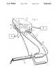
- FIG. 1is a perspective drawing of the endoscopic resecting system which includes a console and the endoscopic viewing and resecting apparatus.
- FIG. 2is a partial longitudinal cross-sectional view of the endoscopic viewing and resecting apparatus of FIG. 1 which includes a compartmentalized tube, a barrier between the compartments of the tube, a visualizing device, an illuminating device and the resecting mechanism.
- FIG. 3is a transverse cross-sectional view of the first endoscopic viewing and resecting apparatus of FIG. 1 taken along the line 3--3 of FIG. 2 which also includes a compartmentalized tube, a barrier between the compartments of the tube, an irrigating apparatus and an aspirating outflow apparatus.
- FIG. 4is a perspective drawing of the sleeve of the endoscopic viewing and resecting apparatus of FIG. 1 into which the compartmentalized tube is inserted.
- FIG.5is a partial perspective drawing of the compartmentalized tube and barrier of the endoscopic viewing and resecting apparatus of FIG. 1.
- FIG. 6is a partial perspective drawing of the resecting mechanism of the first endoscopic viewing and resecting apparatus of FIG. 1.
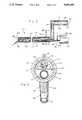
- FIG. 7is a partial longitudinal view in cross-section of the resecting mechanism.
- FIG. 8is a cross-sectional view of the surrounding tissue protecting tube.
- FIG. 9Ais a cross-sectional view of an alternative embodiment of the resecting mechanism.
- FIG. 9Bis a cross-sectional view of the resecting mechanism.
- FIG. 9Cis a cross-sectional view of only the distal end of an alternative embodiment of the resecting mechanism.
- FIG. 9Dis a cross-sectional view of only the distal end of the resecting mechanism.
- FIG. 9Eis a cross-sectional view on another alternative embodiment of the resecting mechanism .
- FIG. 10is a longitudinal view of a second resecting mechanism of a second endoscopic resecting system which includes a console and an endoscopic viewing and resecting apparatus and which has been made in accordance with the principles of the second embodiment of the present invention.
- FIG. 11is a longitudinal view of a third resecting mechanism of third endoscopic resecting system which includes a console and an endoscopic viewing and resecting apparatus and which has been made in accordance with the principles of the third embodiment of the present invention.
- FIG. 12is a longitudinal view of a fourth resecting mechanism of a fourth endoscopic resecting system which includes a console and an endoscopic viewing and resecting apparatus and which has been made in accordance with the principles of the fourth embodiment of the present invention.
- an endoscopic resecting system 10includes a console 20 and an endoscopic viewing and resecting apparatus 110 for viewing and resecting a target tissue from the central nervous system.
- the console 20includes at least five separate modules which are a light source module 21, a motor module 22, a transport medium pump control 23, a transport medium peristaltic pump module 24, and an electrosurgical generator module 30.
- On the front side of the light source module 21are its operating controls which include an on/off toggle power switch, a light source intensity digital read-out, an intensity adjusting rheostat, and a fiber optic cable connection.
- the motor module 22On the front side of the motor module 22 are its operating controls which include an on/off toggle power switch, a motor speed adjustment, and a motor handpiece connection.
- the electronic components of the motor module 22include a connection to a 110 volt external power supply, an on/off toggle power switch, a printed circuit board, a transformer, a heat sink, a speed adjusting control and motor handpiece connection.
- the non-electronic components of the console 20also include support brackets for the power supply, the rheostat used to adjust light intensity, the aperture plate, the light attenuator, the fiber optic cable holder and the lourves near the lamp and in line with air flow from the fan.
- the transport medium pump control module 23includes its operating controls which includes an on/off inflow pump and suction control toggle switch, an inflow rate digital read-out, and inflow rate adjusting rheostat and a suction pressure adjusting rheostat.
- One the side of the transport medium pumps controls module 23is a suction tube occluding device 25 which regulates suction pressure from a suctioning apparatus 26.
- the tube occluding device 25is adjusted to regulate the outflow of the saline and the resected tissue from the surgical site.
- the transport medium pump controls module 23includes a connection to a 110 volt external power supply, an on/off toggle power switch, an inflow rate digital read-out, an inflow rate adjusting rheostat, a printed circuit board for the pump and controls, a printed circuit board for the suction controls, and a suction pressure adjusting rheostat.
- On the side of the peristaltic pump module 24is a pump tubing holder 27 which is mechanically coupled to inflow tubing 28.
- a saline source 29is fluidly coupled to the inflow tubing 28.
- the electronic components of the peristaltic pump module 24includes a connection to pump controls module, a transformer and a motor.
- the non-electronic conmponents of the peristaltic pump module 24include a system of torque dampeners, a pump driver, the peristaltic action producing wheel and a mechanical connector from motor shaft to peristaltic action producing wheel.
- On front side of the electrosurgical generator module 30its operating controls including power switch and power adjusting rheostat. Also on the front side of the electrosurgical generator module 30 are a grounding plate wire connection, footswitch wire connection, and electrode connection.
- the endoscope viewing and resecting apparatus 110includes a compartmentalized tube 112, a visualizing device 113, an illuminating device 114, a first resecting mechanism 115, an irrigating apparatus 116, and an aspirating apparatus 117.
- the suctioning apparatus 26, which is provided in the operating room,is fluidly coupled to the aspirating apparatus 117.
- the irrigating apparatus 116has an inflow connector 119 which is mechanically coupled to the compartmentalized tube near its proximal end and which is fluidly and mechancially coupled to the saline source 29 by the inflow tubing 28.
- the compartmentalized tube 112has a first compartment 121 of a first set of dimensions, a second compartment 122 of a second set of dimensions larger than the first set of dimensions, and a barrier 108 between the first and second compartments.
- the visualizing device 113directly views the target tissue. A portion of the visualizing device 113 is disposed in the first compartment 121.
- the illuminating device 114provides illumination of the target tissue. A portion of the illuminating device 114 is disposed in the first compartment 121.
- the first resecting mechanism 115resects the target tissue. A portion of the first resecting mechanism 115 is disposed in the second compartment 122.
- the inlet 116inlets a transport fluid to the resected target tissue.
- the outlet 117outlets the transport fluid to a suctioning device 26.
- a portion of the outlet 117is disposed in the second compartment 122.
- the visualizing device 113, the illuminating device 114, the first resecting mechanism 115, the inlet 116, and the outlet 117, all functionis an integrated and coordinated manner.
- the visualizing device 113includes a hollow metal sheath 123 and an eyepiece 124. A portion of the hollow metal sheath 123 is disposed in the first compartment 121.
- the eyepiece 124is mechanically and optically coupled to the hollow metal sheath 123 at its proximal end 125.
- the eyepiece 124is disposed at an angle and adjacent to the resecting mechanism 115.
- the visualizing device 113includes a lens train 127 and a forcusing lens 128.
- the lens train 127has a plurality of lenses and is mechanically and optically coupled to the eyepiece 124 and disposed in the hollow metal sheath 123.
- the focusing lens 128is mechanically and optically coupled to the lens train 127 and disposed in the hollow metal sheath 123 at its distal end 126.
- the visualizing device 113may include a coherent optical fiber and a focusing lens.
- the coherent optical fiberis mechanically and optically coupled to the eyepiece 124 and disposed in the metal sheath 123.
- the focusing lens 128is mechanically and optically coupled to the coherent optical fiber and disposed in the metal sheath 123 at its distal end 126.
- a small video cameramay be attached to the eyepiece 124.
- the illuminating mechanism 114includes an optical fiber 129 and a light generator 21. A portion of the optical fiber 129 is disposed within the metal sheath 123 parallel to the lens train and is optically aligned with the lens train 127.
- U.S. Pat. No. 4,601,284entitled Endoscope Connecting System, issued to Satoshi Arakawa and David H. Cooper on July 22, 1986, teaches a video camera which is optically coupled to an eyepiece, an optical-fiber connector which is disposed orthogonally to the eyepiece and a optical fiber.
- the eyepiece 124 and optical fiber 129are disposed contiguously and parallel to one another so that a single cable bundle to the console 20 may be used.
- the light generator 21generates light and is mechanically and optically coupled to the optical fiber 129.
- the illuminating device 114provides illumination of the target tissue. A portion of the illuminating device 114, is disposed in the first compartment 121.
- the visualizing device 113, the illuminating device 114, the first resecting mechanism 115, the irrigating apparatus 116 and the aspirating apparatus 117all function in a coordinated manner.
- the first resecting mechanism 115includes or an outer tube 131, an inner tube 132, and driving mechanism 133.
- the outer tube 131has a proximal end 136 and a distal end 137 and is disposed in the second compartment 122.
- the outer tube 131has a first slot 138 with a first peripheral edge 139 at its distal end 137.
- the inner tube 132has a proximal end 140 and a distal end 141 and is disposed coaxially with and rotatively coupled to the outer tube 131.
- the inner tube 132has a second slot 142 with a second peripheral edge 143 at its distal end 141 and a window 144 at its proximal end 140.
- the driving mechanism 133rotatively drives the inner tube 132 so that the first 139 and second 143 peripheral edge articulate thereby resecting the target tissue.
- the resected target tissue and transport mediumare than aspirated into the lumen 146 of the inner tube 132 at the second slot 142 near the distal end 141 of the inner tube 132.
- the target tissuemoves through the lumen 146 of the inner tube 132 to the window 144 near the proximal end 140 of the inner tube 132.
- the driving mechanism 133includes an electric motor 151 and a power cord 152 the distal end of which is connected to the motor module 22.
- the window 144is disposed adjacent to the outlet connector 134.
- the outer tube 131has a flexible portion 161 which is curved near its distal end 137.
- the flexible portion 161has a proximal end 165 and a distal end 166.
- a plastic material 163covers the flexible portion of the outer tube 131 from the proximal end 165 to the distal end 166.
- the inner tube 132has a flexible portion 145 which is curved near its distal end 141.
- the first resecting mechanism 115has an outer tube 155, an inner tube 156 which is disposed coaxially with and rotatively coupled to the outer tube 155, and is straight with no curved portion.
- the outer tube 155has a first slot 158 which articulates with a second slot 159 on the inner tube 156, thereby resecting the target tissue.
- the driving mechanism 154rotatively drives the inner tube 156 to resect the target tissue.
- an active electrode 104is connected from the proximal end 102 of the first resecting mechanism 115 to the distal end 105.
- a power cordis connected 103 near the proximal end.
- a second resecting mechanism 214includes a tube 215, an active electrode 216, a handpiece 217 and a generator 218.
- the tube 215has a proximal end 219 and a distal end 220.
- a portion of the tube 215is disposed in the second compartment 122 and has a window 221 at its proximal end 219.
- the outer surface 222 of the active electrode 216is coated with a layer 223 of insulating material.
- a portion of the active electrode 216is disposed within the tube 215.
- the active electrode 216may be either monopolar or bipolar.
- the generator 218generates electromagnetic engery in the radio frequency spectrum and is electrically coupled to the active electrode 216 so that the active electrode 216 is heated in order to resect the target tissue.
- Each of U.S. Pat. No. 4,562,838, U.S. Pat. No. 3,974,833, U.S. Pat. No. 3,906,955, U.S. Pat. No. 3,828,928teaches an electrosurgical instrument which has a tube and an electrode for use in high frequency electrocoagulation. The tube either supplies a liquid to the surgical site or aspirates blood and fluid, liquid and/or smoke from the surgical site.
- third resecting mechanism 314includes a tube 315, a transducer 316 and gererator 317.
- the tube 315has a proximal end 318 and a distal end 319 and which is disposed in the second compartment 122.
- the tube 315has a window 320 at its proximal end 318.
- the transducer 316is mechanically coupled to the tube 314 and disposed at its proximal end 318.
- the generator 317generates ultrasonic energy and is electrically coupled to the transducer 316 so that the transducer 316 causes the tube 315 to resonate in order to resect the target tissue.
- a fourth resecting mechanism 414includes a tube 415, a laser 416, and a lightguide 417.
- the tube 415has a proximal end 418 and a distal end 419 and is disposed in the second compartment 122.
- the tube 415has a window 420 at its proximal end 418.
- the laser 416generates light energy.
- the light guide 417is disposed in the tube 415 and guides the light energy so that the conversion of light energy to heat resects the grouting agent or osseus tissue.
- the laser generator of U.S. Pat. No. 3,528,424is a carbon dioxide laser
- other laser generatorsincluding, but not limited to, an excimer laser, a ruby laser, an argon laser, an erbium:YAG laser and a neodymium:YAG laser with an without a contact sapphire tip may be used.
- the endoscopic resecting system 10can be used to remove a target tissue from the central nervous system under direct visual control. All of the engery sources for illumination, target tissue removal, and transportation of debris are conveniently located in the same modularized console 20 so that these processes of the operation are controlled and coordinated.
- the components of the endoscopic resecting system 10 placed partially within the bodyare organized in order to minimize the outer diameter of the compartmentalized tube 24 while still coordinating all of these functions to efficiently and quickly complete the target tissue removal process.
- Direct visual control of the target tissue removal processreduces the need to make large incisions into the body which in turn reduces pain, suffering, and surgical morbidity and also reduces the cost of direct medical care and the overall cost while patients recover from an open operation.
Landscapes
- Health & Medical Sciences (AREA)
- Life Sciences & Earth Sciences (AREA)
- Surgery (AREA)
- Engineering & Computer Science (AREA)
- Public Health (AREA)
- Physics & Mathematics (AREA)
- Biomedical Technology (AREA)
- Heart & Thoracic Surgery (AREA)
- Medical Informatics (AREA)
- Molecular Biology (AREA)
- Animal Behavior & Ethology (AREA)
- General Health & Medical Sciences (AREA)
- Veterinary Medicine (AREA)
- Nuclear Medicine, Radiotherapy & Molecular Imaging (AREA)
- Optics & Photonics (AREA)
- Orthopedic Medicine & Surgery (AREA)
- Vascular Medicine (AREA)
- Mechanical Engineering (AREA)
- Electromagnetism (AREA)
- Otolaryngology (AREA)
- Biophysics (AREA)
- Pathology (AREA)
- Radiology & Medical Imaging (AREA)
- Laser Surgery Devices (AREA)
- Surgical Instruments (AREA)
- Endoscopes (AREA)
Abstract
Description
Claims (9)
Priority Applications (1)
| Application Number | Priority Date | Filing Date | Title |
|---|---|---|---|
| US07/403,185US5085658A (en) | 1989-09-05 | 1989-09-05 | Neurosurgical pathological tissue removing device |
Applications Claiming Priority (1)
| Application Number | Priority Date | Filing Date | Title |
|---|---|---|---|
| US07/403,185US5085658A (en) | 1989-09-05 | 1989-09-05 | Neurosurgical pathological tissue removing device |
Publications (1)
| Publication Number | Publication Date |
|---|---|
| US5085658Atrue US5085658A (en) | 1992-02-04 |
Family
ID=23594792
Family Applications (1)
| Application Number | Title | Priority Date | Filing Date |
|---|---|---|---|
| US07/403,185Expired - LifetimeUS5085658A (en) | 1989-09-05 | 1989-09-05 | Neurosurgical pathological tissue removing device |
Country Status (1)
| Country | Link |
|---|---|
| US (1) | US5085658A (en) |
Cited By (52)
| Publication number | Priority date | Publication date | Assignee | Title |
|---|---|---|---|---|
| US5167620A (en)* | 1989-11-28 | 1992-12-01 | Alexandar Ureche | Eye surgery methods |
| US5195541A (en)* | 1991-10-18 | 1993-03-23 | Obenchain Theodore G | Method of performing laparoscopic lumbar discectomy |
| WO1995001755A1 (en)* | 1992-06-24 | 1995-01-19 | Elliott Martin P | Disposable aspiration tip for a cautery handpiece |
| US5538497A (en)* | 1992-10-28 | 1996-07-23 | Oktas | Endoscope having parasitic light elements |
| US5542432A (en)* | 1992-02-18 | 1996-08-06 | Symbiosis Corporation | Endoscopic multiple sample bioptome |
| US5551448A (en)* | 1991-10-18 | 1996-09-03 | United States Surgical Corporation | Endoscopic surgical instrument for aspiration and irrigation |
| US5562640A (en)* | 1991-10-18 | 1996-10-08 | United States Surgical Corporation | Endoscopic surgical instrument for aspiration and irrigation |
| US5697949A (en)* | 1995-05-18 | 1997-12-16 | Symbiosis Corporation | Small diameter endoscopic instruments |
| US5810744A (en)* | 1993-05-17 | 1998-09-22 | Boston Scientific Corporation | Instrument for collecting multiple biopsy specimens |
| US5871453A (en)* | 1994-02-08 | 1999-02-16 | Boston Scientific Corporation | Moveable sample tube multiple biopsy sampling device |
| US5897507A (en)* | 1996-11-25 | 1999-04-27 | Symbiosis Corporation | Biopsy forceps instrument having irrigation and aspiration capabilities |
| US5919191A (en)* | 1995-01-30 | 1999-07-06 | Boston Scientific Corporation | Electro-surgical tissue removal |
| US6142956A (en)* | 1996-11-25 | 2000-11-07 | Symbiosis Corporation | Proximal actuation handle for a biopsy forceps instrument having irrigation and aspiration capabilities |
| US6142957A (en)* | 1993-09-20 | 2000-11-07 | Boston Scientific Corporation | Multiple biopsy sampling device |
| US6193671B1 (en) | 1994-02-01 | 2001-02-27 | Symbiosis Corporation | Endoscopic multiple sample bioptome with enhanced biting action |
| US6210388B1 (en)* | 1994-04-12 | 2001-04-03 | Sca Hygiene Products Ab | Method for manufacturing a pants-type diaper or sanitary panty, and such an article |
| US20020029006A1 (en)* | 1996-11-25 | 2002-03-07 | Scimed Life Systems, Inc. | Biopsy instrument having irrigation and aspiration capabilities |
| US6428503B1 (en) | 1999-01-19 | 2002-08-06 | Atc Technologies, Inc. | Surgical instrument for providing suction and irrigation |
| US20020107457A1 (en)* | 1996-11-25 | 2002-08-08 | Francese Jose L. | Suction adapter for medical instrument |
| US6494881B1 (en) | 1997-09-30 | 2002-12-17 | Scimed Life Systems, Inc. | Apparatus and method for electrode-surgical tissue removal having a selectively insulated electrode |
| US6589240B2 (en) | 2001-08-28 | 2003-07-08 | Rex Medical, L.P. | Tissue biopsy apparatus with collapsible cutter |
| US20030149442A1 (en)* | 2002-02-04 | 2003-08-07 | Gellman Barry N. | Resistance heated tissue morcellation |
| US6623437B2 (en) | 2001-08-28 | 2003-09-23 | Rex Medical, L.P. | Tissue biopsy apparatus |
| US20040078037A1 (en)* | 2001-05-10 | 2004-04-22 | Gyrus Medical Limited | Surgical instrument |
| US20040186404A1 (en)* | 2003-03-17 | 2004-09-23 | Slater Robert R. | Stabilizer for forearm traction |
| US20070021713A1 (en)* | 2004-01-19 | 2007-01-25 | Atul Kumar | System for distending body tissue cavities by continuous flow irrigation |
| US20070262063A1 (en)* | 2006-05-11 | 2007-11-15 | Kabushiki Kaisha Toshiba | Laser shock hardening method and apparatus |
| US20080065129A1 (en)* | 2006-09-07 | 2008-03-13 | Gyrus Medical Limited | Tissue morcellating device |
| US20080091074A1 (en)* | 2006-10-11 | 2008-04-17 | Alka Kumar | Efficient continuous flow irrigation endoscope |
| US20080091061A1 (en)* | 2006-10-11 | 2008-04-17 | Alka Kumar | Efficient continuous flow irrigation system |
| WO2009124170A1 (en)* | 2008-04-04 | 2009-10-08 | The Cleveland Clinic Foundation | Use of epineural sheath grafts for neural regeneration and protection |
| US20100152614A1 (en)* | 2008-12-16 | 2010-06-17 | Mark Joseph L | Tissue removal device for neurosurgical and spinal surgery applications |
| US20100152756A1 (en)* | 2008-12-16 | 2010-06-17 | Mark Joseph L | Tissue removal device for neurosurgical and spinal surgery applications |
| US20100152758A1 (en)* | 2008-12-16 | 2010-06-17 | Mark Joseph L | Tissue removal device for neurosurgical and spinal surgery applications |
| US20100152760A1 (en)* | 2008-12-16 | 2010-06-17 | Mark Joseph L | Tissue removal device for neurosurgical and spinal surgery applications |
| US20100152533A1 (en)* | 2008-12-16 | 2010-06-17 | Mark Joseph L | Tissue removal device for use with imaging devices in neurosurgical and spinal surgery applications |
| US20100152615A1 (en)* | 2008-12-16 | 2010-06-17 | Mark Joseph L | Tissue removal device with adjustable fluid supply sleeve for neurosurgical and spinal surgery applications |
| US20100152761A1 (en)* | 2008-12-16 | 2010-06-17 | Mark Joseph L | Tissue removal device for neurosurgical and spinal surgery applications |
| US20100249817A1 (en)* | 2008-12-16 | 2010-09-30 | Mark Joseph L | Positioning system for tissue removal device |
| USRE42478E1 (en) | 1994-04-12 | 2011-06-21 | Sca Hygiene Products Aktiebolag | Method of manufacturing a pants-type diaper of a sanitary panty, and one such absorbent article |
| WO2010096139A3 (en)* | 2009-02-20 | 2011-12-01 | Nico Corporation | Tissue removal device for neurosurgical and spinal surgery applications |
| WO2013078402A3 (en)* | 2011-11-23 | 2013-08-15 | Boston Scientific Scimed, Inc. | Tissue and stone removal device |
| US9279751B2 (en) | 2008-12-16 | 2016-03-08 | Nico Corporation | System and method of taking and collecting tissue cores for treatment |
| US9504247B2 (en) | 2008-12-16 | 2016-11-29 | Nico Corporation | System for collecting and preserving tissue cores |
| US9820480B2 (en) | 2008-12-16 | 2017-11-21 | Nico Corporation | System for collecting and preserving tissue cores |
| US9931105B2 (en) | 2008-12-16 | 2018-04-03 | Nico Corporation | System and method of taking and collecting tissue cores for treatment |
| US10080578B2 (en) | 2008-12-16 | 2018-09-25 | Nico Corporation | Tissue removal device with adjustable delivery sleeve for neurosurgical and spinal surgery applications |
| US10368890B2 (en) | 2008-12-16 | 2019-08-06 | Nico Corporation | Multi-functional surgical device for neurosurgical and spinal surgery applications |
| US11129672B2 (en) | 2019-04-04 | 2021-09-28 | Covidien Lp | Tissue resecting device including an articulatable cutting member |
| US11744605B2 (en) | 2020-03-31 | 2023-09-05 | Covidien Lp | Tissue resecting device with deflectable tip |
| US11864823B2 (en) | 2010-10-01 | 2024-01-09 | Applied Medical Resources Corporation | Electrosurgical instruments and connections thereto |
| US11883626B2 (en) | 2019-06-27 | 2024-01-30 | Boston Scientific Scimed, Inc. | Detection of an endoscope to a fluid management system |
Citations (12)
| Publication number | Priority date | Publication date | Assignee | Title |
|---|---|---|---|---|
| US3618611A (en)* | 1969-03-05 | 1971-11-09 | Julius C Urban | Vacuum rotary dissector |
| US3821510A (en)* | 1973-02-22 | 1974-06-28 | H Muncheryan | Hand held laser instrumentation device |
| US3900022A (en)* | 1973-12-10 | 1975-08-19 | Jerrold Widran | Endoscope with uninterrupted flow purging system |
| US4203444A (en)* | 1977-11-07 | 1980-05-20 | Dyonics, Inc. | Surgical instrument suitable for closed surgery such as of the knee |
| US4543857A (en)* | 1983-12-09 | 1985-10-01 | Urban Engineering Co., Inc. | Surgical instrument and method of making same |
| US4550716A (en)* | 1983-04-30 | 1985-11-05 | Olympus Optical Company | Liquid supplying device for endoscope |
| US4598710A (en)* | 1984-01-20 | 1986-07-08 | Urban Engineering Company, Inc. | Surgical instrument and method of making same |
| US4620547A (en)* | 1983-12-31 | 1986-11-04 | Richard Wolf Gmbh | Instrument for sampling tissue specimens |
| US4625713A (en)* | 1982-12-14 | 1986-12-02 | Olympus Optical Co. Ltd. | Instrument incorporated in a resectoscope |
| US4756309A (en)* | 1985-02-14 | 1988-07-12 | Sachse Hans Ernst | Endoscope for removal of tissue |
| US4765314A (en)* | 1985-01-09 | 1988-08-23 | Aesculap-Werke Aktiengesellschaft | Device for introducing an endoscope or a surgical tool into body cavities with a feed for a flushing medium and an extractor for said flushing medium |
| US4955882A (en)* | 1988-03-30 | 1990-09-11 | Hakky Said I | Laser resectoscope with mechanical and laser cutting means |
- 1989
- 1989-09-05USUS07/403,185patent/US5085658A/ennot_activeExpired - Lifetime
Patent Citations (13)
| Publication number | Priority date | Publication date | Assignee | Title |
|---|---|---|---|---|
| US3618611A (en)* | 1969-03-05 | 1971-11-09 | Julius C Urban | Vacuum rotary dissector |
| US3821510A (en)* | 1973-02-22 | 1974-06-28 | H Muncheryan | Hand held laser instrumentation device |
| US3900022A (en)* | 1973-12-10 | 1975-08-19 | Jerrold Widran | Endoscope with uninterrupted flow purging system |
| US4203444B1 (en)* | 1977-11-07 | 1987-07-21 | ||
| US4203444A (en)* | 1977-11-07 | 1980-05-20 | Dyonics, Inc. | Surgical instrument suitable for closed surgery such as of the knee |
| US4625713A (en)* | 1982-12-14 | 1986-12-02 | Olympus Optical Co. Ltd. | Instrument incorporated in a resectoscope |
| US4550716A (en)* | 1983-04-30 | 1985-11-05 | Olympus Optical Company | Liquid supplying device for endoscope |
| US4543857A (en)* | 1983-12-09 | 1985-10-01 | Urban Engineering Co., Inc. | Surgical instrument and method of making same |
| US4620547A (en)* | 1983-12-31 | 1986-11-04 | Richard Wolf Gmbh | Instrument for sampling tissue specimens |
| US4598710A (en)* | 1984-01-20 | 1986-07-08 | Urban Engineering Company, Inc. | Surgical instrument and method of making same |
| US4765314A (en)* | 1985-01-09 | 1988-08-23 | Aesculap-Werke Aktiengesellschaft | Device for introducing an endoscope or a surgical tool into body cavities with a feed for a flushing medium and an extractor for said flushing medium |
| US4756309A (en)* | 1985-02-14 | 1988-07-12 | Sachse Hans Ernst | Endoscope for removal of tissue |
| US4955882A (en)* | 1988-03-30 | 1990-09-11 | Hakky Said I | Laser resectoscope with mechanical and laser cutting means |
Cited By (103)
| Publication number | Priority date | Publication date | Assignee | Title |
|---|---|---|---|---|
| US5167620A (en)* | 1989-11-28 | 1992-12-01 | Alexandar Ureche | Eye surgery methods |
| US5551448A (en)* | 1991-10-18 | 1996-09-03 | United States Surgical Corporation | Endoscopic surgical instrument for aspiration and irrigation |
| US5195541A (en)* | 1991-10-18 | 1993-03-23 | Obenchain Theodore G | Method of performing laparoscopic lumbar discectomy |
| US5607391A (en)* | 1991-10-18 | 1997-03-04 | United States Surgical Corporation | Endoscopic surgical instrument for aspiration and irrigation |
| US5562640A (en)* | 1991-10-18 | 1996-10-08 | United States Surgical Corporation | Endoscopic surgical instrument for aspiration and irrigation |
| US5542432A (en)* | 1992-02-18 | 1996-08-06 | Symbiosis Corporation | Endoscopic multiple sample bioptome |
| US5951488A (en)* | 1992-02-18 | 1999-09-14 | Symbiosis Corporation | Endoscopic multiple sample bioptome |
| WO1995001755A1 (en)* | 1992-06-24 | 1995-01-19 | Elliott Martin P | Disposable aspiration tip for a cautery handpiece |
| US5538497A (en)* | 1992-10-28 | 1996-07-23 | Oktas | Endoscope having parasitic light elements |
| US5895350A (en)* | 1992-10-28 | 1999-04-20 | Vista Medical Technologies, Inc. | Electronic endoscope |
| US5810744A (en)* | 1993-05-17 | 1998-09-22 | Boston Scientific Corporation | Instrument for collecting multiple biopsy specimens |
| US6142957A (en)* | 1993-09-20 | 2000-11-07 | Boston Scientific Corporation | Multiple biopsy sampling device |
| US6561988B1 (en) | 1994-02-01 | 2003-05-13 | Symbiosis Corporation | Endoscopic multiple sample bioptome with enhanced biting action |
| US6193671B1 (en) | 1994-02-01 | 2001-02-27 | Symbiosis Corporation | Endoscopic multiple sample bioptome with enhanced biting action |
| US5871453A (en)* | 1994-02-08 | 1999-02-16 | Boston Scientific Corporation | Moveable sample tube multiple biopsy sampling device |
| US6053877A (en)* | 1994-02-08 | 2000-04-25 | Boston Scientific Corporation | Movable sample tube multiple biopsy sampling device |
| USRE42478E1 (en) | 1994-04-12 | 2011-06-21 | Sca Hygiene Products Aktiebolag | Method of manufacturing a pants-type diaper of a sanitary panty, and one such absorbent article |
| US6210388B1 (en)* | 1994-04-12 | 2001-04-03 | Sca Hygiene Products Ab | Method for manufacturing a pants-type diaper or sanitary panty, and such an article |
| US5919191A (en)* | 1995-01-30 | 1999-07-06 | Boston Scientific Corporation | Electro-surgical tissue removal |
| US5697949A (en)* | 1995-05-18 | 1997-12-16 | Symbiosis Corporation | Small diameter endoscopic instruments |
| US20020029006A1 (en)* | 1996-11-25 | 2002-03-07 | Scimed Life Systems, Inc. | Biopsy instrument having irrigation and aspiration capabilities |
| US7297121B2 (en) | 1996-11-25 | 2007-11-20 | Boston Scientific Scimed, Inc. | Biopsy instrument having irrigation and aspiration capabilities |
| US6142956A (en)* | 1996-11-25 | 2000-11-07 | Symbiosis Corporation | Proximal actuation handle for a biopsy forceps instrument having irrigation and aspiration capabilities |
| US20020107457A1 (en)* | 1996-11-25 | 2002-08-08 | Francese Jose L. | Suction adapter for medical instrument |
| US6926676B2 (en) | 1996-11-25 | 2005-08-09 | Boston Scientific Scimed, Inc. | Biopsy instrument having irrigation and aspiration capabilities |
| US6544194B1 (en) | 1996-11-25 | 2003-04-08 | Symbiosis Corporation | Proximal actuation handle for a biopsy forceps instrument having irrigation and aspiration capabilities |
| US5897507A (en)* | 1996-11-25 | 1999-04-27 | Symbiosis Corporation | Biopsy forceps instrument having irrigation and aspiration capabilities |
| US7204811B2 (en) | 1996-11-25 | 2007-04-17 | Boston Scientific Miami Corporation | Proximal actuation handle for a biopsy forceps instrument having irrigation and aspiration capabilities |
| US7833167B2 (en) | 1996-11-25 | 2010-11-16 | Boston Scientific Miami Corporation | Proximal actuation handle for a biopsy forceps instrument having irrigation and aspiration capabilities |
| US6174292B1 (en) | 1996-11-25 | 2001-01-16 | Symbiosis Corporation | Biopsy forceps instrument having irrigation and aspiration capabilities |
| US20050245841A1 (en)* | 1996-11-25 | 2005-11-03 | Vincent Turturro | Biopsy instrument having irrigation and aspiration capabilities |
| US7347828B2 (en) | 1996-11-25 | 2008-03-25 | Boston Scientific Miami Corporation | Suction adapter for medical instrument |
| US20070270709A1 (en)* | 1996-11-25 | 2007-11-22 | Boston Scientific Miami Corporation | Proximal actuation handle for a biopsy forceps instrument having irrigation and aspiration capabilities |
| US6832990B2 (en) | 1996-11-25 | 2004-12-21 | Symbiosis Corporation | Biopsy instrument having aspiration capabilities |
| US6494881B1 (en) | 1997-09-30 | 2002-12-17 | Scimed Life Systems, Inc. | Apparatus and method for electrode-surgical tissue removal having a selectively insulated electrode |
| US6428503B1 (en) | 1999-01-19 | 2002-08-06 | Atc Technologies, Inc. | Surgical instrument for providing suction and irrigation |
| US6827725B2 (en)* | 2001-05-10 | 2004-12-07 | Gyrus Medical Limited | Surgical instrument |
| US20040078037A1 (en)* | 2001-05-10 | 2004-04-22 | Gyrus Medical Limited | Surgical instrument |
| US6623437B2 (en) | 2001-08-28 | 2003-09-23 | Rex Medical, L.P. | Tissue biopsy apparatus |
| US6589240B2 (en) | 2001-08-28 | 2003-07-08 | Rex Medical, L.P. | Tissue biopsy apparatus with collapsible cutter |
| US6997926B2 (en) | 2002-02-04 | 2006-02-14 | Boston Scientific Scimed, Inc. | Resistance heated tissue morcellation |
| US20030149442A1 (en)* | 2002-02-04 | 2003-08-07 | Gellman Barry N. | Resistance heated tissue morcellation |
| US7143458B2 (en) | 2003-03-17 | 2006-12-05 | Slater Jr Robert R | Stabilizer for forearm traction |
| US20040186404A1 (en)* | 2003-03-17 | 2004-09-23 | Slater Robert R. | Stabilizer for forearm traction |
| US9101701B2 (en) | 2004-01-19 | 2015-08-11 | Arthrex, Inc. | System for distending body tissue cavities by continuous flow irrigation |
| US8652089B2 (en)* | 2004-01-19 | 2014-02-18 | Arthrex, Inc. | System for distending body tissue cavities by continuous flow irrigation |
| US20070021713A1 (en)* | 2004-01-19 | 2007-01-25 | Atul Kumar | System for distending body tissue cavities by continuous flow irrigation |
| US8872058B2 (en) | 2006-05-11 | 2014-10-28 | Kabushiki Kaisha Toshiba | Laser shock hardening apparatus |
| US20100170877A1 (en)* | 2006-05-11 | 2010-07-08 | Kabushiki Kaisha Toshiba | Laser shock hardening method and apparatus |
| US8304686B2 (en) | 2006-05-11 | 2012-11-06 | Kabushiki Kaisha Toshiba | Laser shock hardening method and apparatus |
| US20070262063A1 (en)* | 2006-05-11 | 2007-11-15 | Kabushiki Kaisha Toshiba | Laser shock hardening method and apparatus |
| US8330070B2 (en)* | 2006-05-11 | 2012-12-11 | Kabushiki Kaisha Toshiba | Laser shock hardening method and apparatus |
| US20080065129A1 (en)* | 2006-09-07 | 2008-03-13 | Gyrus Medical Limited | Tissue morcellating device |
| US9155453B2 (en)* | 2006-10-11 | 2015-10-13 | Alka Kumar | Efficient continuous flow irrigation endoscope |
| US20080091061A1 (en)* | 2006-10-11 | 2008-04-17 | Alka Kumar | Efficient continuous flow irrigation system |
| US8911363B2 (en) | 2006-10-11 | 2014-12-16 | Alka Kumar | Efficient continuous flow irrigation system |
| US20080091074A1 (en)* | 2006-10-11 | 2008-04-17 | Alka Kumar | Efficient continuous flow irrigation endoscope |
| US10028763B2 (en) | 2006-10-11 | 2018-07-24 | Alka Kumar | Efficient continuous flow irrigation endoscope |
| US8226549B2 (en)* | 2006-10-11 | 2012-07-24 | Alka Kumar | Efficient continuous flow irrigation system |
| WO2009124170A1 (en)* | 2008-04-04 | 2009-10-08 | The Cleveland Clinic Foundation | Use of epineural sheath grafts for neural regeneration and protection |
| US20110087338A1 (en)* | 2008-04-04 | 2011-04-14 | The Cleveland Clinic Foundation | Use of Epineural Sheath Grafts for Neural Regeneration and Protection |
| US9820747B2 (en) | 2008-04-04 | 2017-11-21 | The Cleveland Clinic Foundation | Use of epineural sheath grafts for neural regeneration and protection |
| US20100152758A1 (en)* | 2008-12-16 | 2010-06-17 | Mark Joseph L | Tissue removal device for neurosurgical and spinal surgery applications |
| US10368890B2 (en) | 2008-12-16 | 2019-08-06 | Nico Corporation | Multi-functional surgical device for neurosurgical and spinal surgery applications |
| US11759259B2 (en) | 2008-12-16 | 2023-09-19 | Nico Corporation | Tissue removal device with adjustable delivery sleeve for neurosurgical and spinal surgery applications |
| WO2010077931A3 (en)* | 2008-12-16 | 2010-11-25 | Nico Corporation | Tissue removal device with adjustable fluid supply sleeve for neurosurgical and spinal surgery applications |
| US8357175B2 (en) | 2008-12-16 | 2013-01-22 | Nico Corporation | Positioning system for tissue removal device |
| US8430825B2 (en) | 2008-12-16 | 2013-04-30 | Nico Corporation | Tissue removal device for neurosurgical and spinal surgery applications |
| US8460327B2 (en) | 2008-12-16 | 2013-06-11 | Nico Corporation | Tissue removal device for neurosurgical and spinal surgery applications |
| US8496599B2 (en)* | 2008-12-16 | 2013-07-30 | Nico Corporation | Tissue removal device for neurosurgical and spinal surgery applications |
| US11609160B2 (en) | 2008-12-16 | 2023-03-21 | Nico Corporation | System and method of taking and collecting tissue cores for treatment |
| US20100249817A1 (en)* | 2008-12-16 | 2010-09-30 | Mark Joseph L | Positioning system for tissue removal device |
| US8657841B2 (en) | 2008-12-16 | 2014-02-25 | Nico Corporation | Tissue removal device for neurosurgical and spinal surgery applications |
| US8702738B2 (en)* | 2008-12-16 | 2014-04-22 | Nico Corporation | Tissue removal device for neurosurgical and spinal surgery applications |
| US20100152761A1 (en)* | 2008-12-16 | 2010-06-17 | Mark Joseph L | Tissue removal device for neurosurgical and spinal surgery applications |
| US8888803B2 (en) | 2008-12-16 | 2014-11-18 | Nico Corporation | Tissue removal device for neurosurgical and spinal surgery applications |
| US10959424B2 (en) | 2008-12-16 | 2021-03-30 | Nico Corporation | System for collecting and preserving tissue cores |
| US20100152615A1 (en)* | 2008-12-16 | 2010-06-17 | Mark Joseph L | Tissue removal device with adjustable fluid supply sleeve for neurosurgical and spinal surgery applications |
| US9028518B2 (en) | 2008-12-16 | 2015-05-12 | Nico Corporation | Tissue removal device for neurosurgical and spinal surgery applications |
| US20100152533A1 (en)* | 2008-12-16 | 2010-06-17 | Mark Joseph L | Tissue removal device for use with imaging devices in neurosurgical and spinal surgery applications |
| US20100152760A1 (en)* | 2008-12-16 | 2010-06-17 | Mark Joseph L | Tissue removal device for neurosurgical and spinal surgery applications |
| US9216031B2 (en) | 2008-12-16 | 2015-12-22 | Nico Corporation | Tissue removal device with adjustable fluid supply sleeve for neurosurgical and spinal surgery applications |
| US9279751B2 (en) | 2008-12-16 | 2016-03-08 | Nico Corporation | System and method of taking and collecting tissue cores for treatment |
| US10398462B2 (en) | 2008-12-16 | 2019-09-03 | Nico Corporation | Tissue removal device with adjustable sleeve for neurosurgical and spinal surgery applications |
| US9504247B2 (en) | 2008-12-16 | 2016-11-29 | Nico Corporation | System for collecting and preserving tissue cores |
| US9655639B2 (en)* | 2008-12-16 | 2017-05-23 | Nico Corporation | Tissue removal device for use with imaging devices in neurosurgical and spinal surgery applications |
| US20100152756A1 (en)* | 2008-12-16 | 2010-06-17 | Mark Joseph L | Tissue removal device for neurosurgical and spinal surgery applications |
| US9820480B2 (en) | 2008-12-16 | 2017-11-21 | Nico Corporation | System for collecting and preserving tissue cores |
| US9931105B2 (en) | 2008-12-16 | 2018-04-03 | Nico Corporation | System and method of taking and collecting tissue cores for treatment |
| US10080578B2 (en) | 2008-12-16 | 2018-09-25 | Nico Corporation | Tissue removal device with adjustable delivery sleeve for neurosurgical and spinal surgery applications |
| US20100152614A1 (en)* | 2008-12-16 | 2010-06-17 | Mark Joseph L | Tissue removal device for neurosurgical and spinal surgery applications |
| US10048176B2 (en) | 2008-12-16 | 2018-08-14 | Nico Corporation | System and method of taking and collecting tissue cores for treatment |
| JP2012518463A (en)* | 2009-02-20 | 2012-08-16 | ニコ・コーポレーション | Tissue removal device for neurosurgery and spinal surgery applications |
| AU2009340436B2 (en)* | 2009-02-20 | 2014-11-27 | Stryker Corporation | Neurosurgical tissue removal assembly |
| WO2010096139A3 (en)* | 2009-02-20 | 2011-12-01 | Nico Corporation | Tissue removal device for neurosurgical and spinal surgery applications |
| US11864823B2 (en) | 2010-10-01 | 2024-01-09 | Applied Medical Resources Corporation | Electrosurgical instruments and connections thereto |
| US10004560B2 (en) | 2011-11-23 | 2018-06-26 | Boston Scientific Scimed, Inc. | Tissue and stone removal device and related methods of use |
| US9393033B2 (en) | 2011-11-23 | 2016-07-19 | Boston Scientific Scimed, Inc. | Tissue and stone removal device and related methods of use |
| US10463432B2 (en) | 2011-11-23 | 2019-11-05 | Boston Scientific Scimed, Inc. | Tissue and stone removal device and related methods of use |
| WO2013078402A3 (en)* | 2011-11-23 | 2013-08-15 | Boston Scientific Scimed, Inc. | Tissue and stone removal device |
| US11129672B2 (en) | 2019-04-04 | 2021-09-28 | Covidien Lp | Tissue resecting device including an articulatable cutting member |
| US11883626B2 (en) | 2019-06-27 | 2024-01-30 | Boston Scientific Scimed, Inc. | Detection of an endoscope to a fluid management system |
| US11744605B2 (en) | 2020-03-31 | 2023-09-05 | Covidien Lp | Tissue resecting device with deflectable tip |
Similar Documents
| Publication | Publication Date | Title |
|---|---|---|
| US5085658A (en) | Neurosurgical pathological tissue removing device | |
| US4998527A (en) | Endoscopic abdominal, urological, and gynecological tissue removing device | |
| US5027792A (en) | Endoscopic revision hip surgery device | |
| US11172986B2 (en) | Ablation with energy carried in fluid stream | |
| US5131382A (en) | Endoscopic percutaneous discectomy device | |
| Wuchinich et al. | Endoscopic ultrasonic rotary electro-cauterizing aspirator | |
| US5498258A (en) | Laser resectoscope with laser induced mechanical cutting means | |
| US5102410A (en) | Soft tissue cutting aspiration device and method | |
| US5011483A (en) | Combined electrosurgery and laser beam delivery device | |
| US6610059B1 (en) | Endoscopic instruments and methods for improved bubble aspiration at a surgical site | |
| CA2273925C (en) | Mechanical and electrical endoscopic surgical instrument | |
| US6159209A (en) | Automatic resectoscope | |
| US5456689A (en) | Method and device for tissue resection | |
| US20080194999A1 (en) | Ultrasonic treatment apparatus and treatment method | |
| US20100022824A1 (en) | Tissue modification devices and methods of using the same | |
| JP2911689B2 (en) | Surgical handpiece | |
| KR20010052456A (en) | Device and method for resecting body tissues | |
| JP2007528239A (en) | Tissue removal apparatus and method | |
| US10842587B2 (en) | Method for minimally invasive surgery using therapeutic ultrasound to treat spine and orthopedic diseases, injuries and deformities | |
| EP1809378A1 (en) | Devices and methods for the treatment of endometriosis | |
| US20130144281A1 (en) | Tissue Treatment Apparatus with Interchangeable Instrument/Accessories | |
| US6090103A (en) | Interstitial laser resectoscope | |
| JP3631388B2 (en) | Surgery system | |
| JP2019092843A (en) | Laser transmission line, laser treatment instrument, laser treatment device, and laser treatment system | |
| JPH0759789A (en) | Handpiece for surgery |
Legal Events
| Date | Code | Title | Description |
|---|---|---|---|
| AS | Assignment | Owner name:PERCUTANEOUS TECHNOLOGIES INC.,, CALIFORNIA Free format text:ASSIGNMENT OF ASSIGNORS INTEREST.;ASSIGNOR:MEYER, WILLIAM F.;REEL/FRAME:005272/0650 Effective date:19890901 | |
| STCF | Information on status: patent grant | Free format text:PATENTED CASE | |
| AS | Assignment | Owner name:KARL STORZ-ENDOSCOPY-AMERICA, INC. (CALIFORNIA CO Free format text:ASSIGNMENT OF ASSIGNORS INTEREST;ASSIGNORS:PERCUTANEOUS TECHNOLOGIES, INC.;MEYER, WILLIAM FRANCIS;REEL/FRAME:007372/0230 Effective date:19931129 | |
| REMI | Maintenance fee reminder mailed | ||
| FEPP | Fee payment procedure | Free format text:PAT HLDR NO LONGER CLAIMS SMALL ENT STAT AS INDIV INVENTOR (ORIGINAL EVENT CODE: LSM1); ENTITY STATUS OF PATENT OWNER: LARGE ENTITY | |
| FPAY | Fee payment | Year of fee payment:4 | |
| SULP | Surcharge for late payment | ||
| REMI | Maintenance fee reminder mailed | ||
| REFU | Refund | Free format text:REFUND - SURCHARGE FOR LATE PAYMENT, LARGE ENTITY (ORIGINAL EVENT CODE: R186); ENTITY STATUS OF PATENT OWNER: LARGE ENTITY Free format text:REFUND - PAYMENT OF MAINTENANCE FEE, 4TH YEAR, LARGE ENTITY (ORIGINAL EVENT CODE: R183); ENTITY STATUS OF PATENT OWNER: LARGE ENTITY | |
| FPAY | Fee payment | Year of fee payment:8 | |
| SULP | Surcharge for late payment | ||
| FPAY | Fee payment | Year of fee payment:12 |