US5085652A - Pouch with mounting member for removable adhesive filter - Google Patents
Pouch with mounting member for removable adhesive filterDownload PDFInfo
- Publication number
- US5085652A US5085652AUS07/367,237US36723789AUS5085652AUS 5085652 AUS5085652 AUS 5085652AUS 36723789 AUS36723789 AUS 36723789AUS 5085652 AUS5085652 AUS 5085652A
- Authority
- US
- United States
- Prior art keywords
- pouch
- vent
- mounting member
- filter
- mounting
- Prior art date
- Legal status (The legal status is an assumption and is not a legal conclusion. Google has not performed a legal analysis and makes no representation as to the accuracy of the status listed.)
- Expired - Lifetime
Links
- 239000000853adhesiveSubstances0.000titleclaimsabstractdescription26
- 230000001070adhesive effectEffects0.000titleclaimsabstractdescription26
- 239000004820Pressure-sensitive adhesiveSubstances0.000claimsabstractdescription7
- 239000007789gasSubstances0.000claimsdescription19
- -1polyethylenePolymers0.000claimsdescription9
- 239000004698PolyethyleneSubstances0.000claimsdescription7
- 229920000573polyethylenePolymers0.000claimsdescription7
- DQXBYHZEEUGOBF-UHFFFAOYSA-Nbut-3-enoic acid;etheneChemical compoundC=C.OC(=O)CC=CDQXBYHZEEUGOBF-UHFFFAOYSA-N0.000claimsdescription5
- 239000005038ethylene vinyl acetateSubstances0.000claimsdescription5
- 229920001200poly(ethylene-vinyl acetate)Polymers0.000claimsdescription5
- 239000000203mixtureSubstances0.000claimsdescription4
- 239000002699waste materialSubstances0.000claimsdescription3
- 239000000463materialSubstances0.000abstractdescription18
- 230000001877deodorizing effectEffects0.000abstractdescription11
- OKTJSMMVPCPJKN-UHFFFAOYSA-NCarbonChemical compound[C]OKTJSMMVPCPJKN-UHFFFAOYSA-N0.000description9
- 239000006260foamSubstances0.000description7
- 235000019645odorNutrition0.000description6
- 239000010410layerSubstances0.000description5
- 230000008878couplingEffects0.000description4
- 238000010168coupling processMethods0.000description4
- 238000005859coupling reactionMethods0.000description4
- 238000013022ventingMethods0.000description3
- 238000010276constructionMethods0.000description2
- 229920001577copolymerPolymers0.000description2
- 239000007788liquidSubstances0.000description2
- 238000012986modificationMethods0.000description2
- 230000004048modificationEffects0.000description2
- 229920003023plasticPolymers0.000description2
- 239000004033plasticSubstances0.000description2
- 229920001343polytetrafluoroethylenePolymers0.000description2
- 229920002635polyurethanePolymers0.000description2
- 239000004814polyurethaneSubstances0.000description2
- 230000037303wrinklesEffects0.000description2
- 206010000060Abdominal distensionDiseases0.000description1
- 229920001328Polyvinylidene chloridePolymers0.000description1
- BZHJMEDXRYGGRV-UHFFFAOYSA-NVinyl chlorideChemical compoundClC=CBZHJMEDXRYGGRV-UHFFFAOYSA-N0.000description1
- 210000003815abdominal wallAnatomy0.000description1
- 238000009825accumulationMethods0.000description1
- 239000012790adhesive layerSubstances0.000description1
- 230000000712assemblyEffects0.000description1
- 238000000429assemblyMethods0.000description1
- 238000003287bathingMethods0.000description1
- 229910052799carbonInorganic materials0.000description1
- 238000004332deodorizationMethods0.000description1
- 239000004744fabricSubstances0.000description1
- 239000012530fluidSubstances0.000description1
- 238000007455ileostomyMethods0.000description1
- 230000002262irrigationEffects0.000description1
- 238000003973irrigationMethods0.000description1
- 238000000034methodMethods0.000description1
- 239000002245particleSubstances0.000description1
- 230000037081physical activityEffects0.000description1
- 229920001296polysiloxanePolymers0.000description1
- 229920000915polyvinyl chloridePolymers0.000description1
- 239000004800polyvinyl chlorideSubstances0.000description1
- 239000005033polyvinylidene chlorideSubstances0.000description1
- 239000005871repellentSubstances0.000description1
- 238000007789sealingMethods0.000description1
- 239000007787solidSubstances0.000description1
- 239000002910solid wasteSubstances0.000description1
- 238000001356surgical procedureMethods0.000description1
- XLYOFNOQVPJJNP-UHFFFAOYSA-NwaterSubstancesOXLYOFNOQVPJJNP-UHFFFAOYSA-N0.000description1
- 238000003466weldingMethods0.000description1
Images


Classifications
- A—HUMAN NECESSITIES
- A61—MEDICAL OR VETERINARY SCIENCE; HYGIENE
- A61B—DIAGNOSIS; SURGERY; IDENTIFICATION
- A61B17/00—Surgical instruments, devices or methods
- A61B17/32—Surgical cutting instruments
- A61B17/3205—Excision instruments
- A61B17/32053—Punch like cutting instruments, e.g. using a cylindrical or oval knife
- A—HUMAN NECESSITIES
- A61—MEDICAL OR VETERINARY SCIENCE; HYGIENE
- A61F—FILTERS IMPLANTABLE INTO BLOOD VESSELS; PROSTHESES; DEVICES PROVIDING PATENCY TO, OR PREVENTING COLLAPSING OF, TUBULAR STRUCTURES OF THE BODY, e.g. STENTS; ORTHOPAEDIC, NURSING OR CONTRACEPTIVE DEVICES; FOMENTATION; TREATMENT OR PROTECTION OF EYES OR EARS; BANDAGES, DRESSINGS OR ABSORBENT PADS; FIRST-AID KITS
- A61F5/00—Orthopaedic methods or devices for non-surgical treatment of bones or joints; Nursing devices ; Anti-rape devices
- A61F5/44—Devices worn by the patient for reception of urine, faeces, catamenial or other discharge; Colostomy devices
- A61F5/441—Devices worn by the patient for reception of urine, faeces, catamenial or other discharge; Colostomy devices having venting or deodorant means, e.g. filters ; having antiseptic means, e.g. bacterial barriers
Definitions
- the present inventionrelates to medical devices of the type including collection receptacles with deodorizing filters and more particularly with a medical device which includes a collection receptacle or pouch having a mounting member bonded thereto and adapted to facilitate removable mounting of a deodorizing filter assembly or cover element.
- an appliancewhich includes a collection receptacle in the form of a pouch or bag which is affixed to the patient in alignment with the stoma. The appliance collects waste as it is discharged and also protects the stoma.
- receptaclesmay be in the form of a pouch or bag as well.
- Such collection pouches or bagsare often formed of thin sheets of material welded along the periphery.
- the materialsare generally composed of light weight, odor proof, flexible polymeric plastic.
- the gas venting problemhas been subjected to a variety of different solutions. Some pouches have been provided with a tortuous path vent opening, with or without a deodorizing filter. Others have been provided with openings in the pouch wall, covered with deodorizing filters. Another approach has been to provide replaceable filters attached to the bag by a series of plural sequentially peelable adhesive members.
- Certain ostomy systemssuch as that disclosed in U.S. Pat. No. 4,460,363 to Steer et al., permit pouches to be removed and reused, hence prolonging the useful life of the pouch beyond the useful life of a single filter. It is therefore often necessary that the deodorizing filter itself be replaced periodically in order to insure that complete deodorization is taking place. On the other hand, it may be desirable, in certain instances, to eliminate the deodorizing filter completely, and simply seal the vent. Accordingly, it is most desirable to have a structure where the filter can be removed as necessary so that it can be replaced or the vent can be obstructed. The use of adhesive coated elements is particularly well adopted for this purpose.
- Prior art pouches adapted for use with filterseither have had the filters permanently bonded to the pouch wall, such as by heat or impulse welding or, if removable filter mounting is employed, the filter is adhesively mounted directly to the pouch wall surrounding the vent opening.
- the pouch wallis made of a material which, in the latter case, does not permit an adhesive element to be easily removed and replaced. Because the pouch wall is so thin, an adhesive strong enough to make the required seal will often cause the wall to tear around the vent opening as the filter is removed, clearly a severe disadvantage.
- the pouch wallis so thin surrounding the vent opening that it tends to wrinkle, preventing a good seal with adhesive coated filter.
- a pouchhas been designed with a mounting member permanently affixed to the pouch wall surrounding the vent opening.
- the mounting memberis made of a material which is compatible with the pouch film such that it can be permanently bonded thereto. It has an exterior surface which is adapted to facilitate sealing engagement with an adhesive coated element, which may be a filter assembly or a cover element.
- the mounting memberserves to increase the effectiveness of the adhesive seal by providing a wrinkle-free mounting surface compatible with the adhesive and at the same time prevent the pouch wall from being torn along the vent opening as the adhesive element is removed therefrom.
- a devicecomprising a collection receptacle in the form of a thin walled pouch.
- the pouchcomprises a vent through which gaseous matter may escape.
- a mounting memberis affixed to the pouch wall, surrounding the vent.
- the memberhas an opening aligned with the vent such that the passage of gases through the vent is substantially unobstructed.
- the memberhas an exterior surface adapted to facilitate removable mounting of an adhesive element in alignment with the vent.
- the mounting memberis composed of a material which is compatible with the material of the pouch wall.
- the mounting memberis composed of a mixture of polyethylene and ethylene vinyl acetate.
- itis annular in configuration.
- the removable elementmay be in the form of gas impermeable cover element coated with a pressure sensitive adhesive.
- the cover elementhas a substantially circular configuration with a radially extending tab.
- the removable elementmay comprise a filter assembly including a filter disk and a means for encapsuling the filter disk.
- the filter diskmay comprise an open cell foam treated with activated carbon.
- the encapsulating meansmay comprise thin sheets of microporous film between which the filter disk is sandwiched. The films preferably have a bonded edge and are preferably treated to be liquid impervious.
- a substantially annular border memberis provided as part of the assembly.
- the border memberis composed of a closed cell foam. It is preferably coplanar with and surrounds the filter disk.
- the border memberis coated with a pressure sensitive adhesive layer.
- An exterior film layermay be provided with an opening. The exterior layer is bonded to the filter disk and the border member.
- a deviceincluding a collection receptacle in the form a thin walled pouch.
- the pouchhas a vent through which gaseous matter may escape.
- a mounting memberis affixed to the pouch wall surrounding the vent.
- the memberhas an opening aligned with the vent such that passage of gases through the vent is substantially unobstructed.
- the memberis adapted to permit removable mounting of an adhesive coated filter element in alignment with the opening such that gases are filtered through the element as they pass from the pouch.
- a devicecomprising a collection receptacle in the form of a thin walled pouch.
- the pouchincludes a vent through which gaseous matter may escape.
- a mounting memberis affixed to the pouch wall surrounding the vent. The member has an opening aligned with the vent such that the passage of gases through the vent is substantially unobstructed.
- the mounting memberis adapted to permit removable mounting of a cover element over the opening such that gases are prevented from escaping through the vent.
- a devicecomprising a collection receptacle in the form of a thin walled pouch is provided in combination with a member affixed to the wall of the pouch and punch means for creating a vent through the member and wall.
- the memberonce punched, defines a border surrounding the vent adapted to facilitate removable mounting of a filter assembly in alignment with the vent.
- the punch meanspreferably comprises first and second hingeably connected parts.
- a protrusionextends from one of the parts.
- a recessis formed in the other of the parts. The protrusion and the recess are adapted to align with the member therebetween.
- the filter assemblypreferably comprises a filter disk, microporous film for encapsulating the disk and an annular border member.
- the border memberis coated with an adhesive.
- the present inventionrelates to an ostomy pouch with a mounting member for an adhesive filter, as set forth in detail in the following specification and recited in the annexed claims, taken together with the accompanying drawings, wherein like numerals refer to like parts, and in which:
- FIG. 1is an exploded isometric view of an ostomy pouch including the mounting members of the present invention, showing a cover member and a filter element alternately mountable thereon.
- FIG. 2is a plan view of the top portion of the rear of the pouch wall showing a cover element mounted thereon;
- FIG. 3is a view similar to FIG. 2 but showing the pouch with a filter element mounted thereon;
- FIG. 4is a cross-sectional view taken along line 4--4 of FIG. 2;
- FIG. 5is a cross-sectional view taken along line 5--5 of FIG. 3;
- FIG. 6is a plan view of the top portion of the rear of a pouch wall illustrating a second preferred embodiment of the present invention
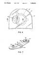
- FIG. 7is an isometric view of a punch used in conjunction with the pouch illustrated in FIG. 6;
- FIG. 8is a cross-sectional view of the pouch wall illustrated in FIG. 6 taken along line 8--8;
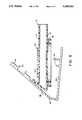
- FIG. 9is a cross-sectional view showing the punch of FIG. 7 in the open position, with a portion of the pouch therein;
- FIG. 10is a view similar to FIG. 9 but showing the punch in the closed position.
- FIG. 11is a cross-sectional view similar to that shown in FIG. 8 but illustrating the pouch after the vent has been punched.
- the first preferred embodiment of the present inventionincludes a collection receptacle in the form of a pouch, generally designated A.
- Pouch Aincludes a rear wall 10 and a front wall 12 made of thin, flexible, preferably transparent, film which is heat welded around the periphery to form an enclosed receptacle.
- the pouch illustrated in the drawingsis of the type utilized in a so-called "two-piece" ostomy appliance; that is, an appliance in which the pouch is detachably mounted to an adhesive coated dressing designed to be affixed to the body surrounding the stoma. It should be appreciated that while the present invention is illustrated in conjunction with a detachable pouch of the closed variety, it is equally applicable to one-piece type appliances wherein the pouch is permanently affixed to the dressing. The particular configuration of the pouch plays no portion in the present invention which is equally applicable to all pouch styles.
- the films from which the pouch may be madeare selected from materials which possess the properties of being moisture impermeable, odor impermeable and capable of being heat sealed or impulse welded. Suitable materials include polyethylene, copolymers of polyethylene and ethylene vinyl acetate, copolymers of vinyl chloride and polyvinylidene chloride and laminates thereof.
- the pouch wallsare preferably from about 2-4 mils thick.
- Wall 12is provided with a stoma receiving opening 14 which is defined by a coupling ring 16 of the type which is conventional in two-piece ostomy devices such as those disclosed in Steer U.S. Pat. No. 4,460,363.
- Rear wall 10is provided with a circular vent 18 which is preferably centered approximately in alignment with a portion of the coupling ring 16.
- a mounting member 20Surrounding vent 18 is a mounting member 20 which is permanently affixed or laminated to the pouch wall surrounding the vent. Member 20 preferably has an annular configuration.
- Mounting member 20is made of a material which exhibits superior characteristics when a pressure-sensitive adhesive is applied to it and peeled from it.
- the thickness of the mounting membereliminates folds and wrinkles in the pouch film which prevent a fluid tight seal between the wall and the filter assembly. Stress exerted on the pouch film as a filter is removed is more evenly distributed by the mounting member, preventing tears in the film which otherwise would start adjacent at the vent.
- the mounting memberpreferably comprises a blend of polyethylene and ethylene vinyl acetate which is compatible with the pouch film.
- mounting member 20comprises a disk 22 affixed to the outer surface of wall 10 surrounding opening 18.
- mounting member 20is adapted to affix either a filter assembly, generally designated 26 or cover member 28 over the vent. It should be appreciated that the vent in member 20 is preferably relatively large so as not to become obscured by solid or semi-solid waste.
- filter assemblyWhile a variety of different filter assemblies may be utilized, it is preferable to use an assembly which permits movement of gas therethrough in a direction substantially perpendicular to its surface.
- the filter assembly illustrated in the drawingsis of the type described in Steer, U.S. Pat. No. 4,668,258, and is believed to be preferable for this purpose.
- the precise structure of the filter assemblyplays no part in the present invention and should not be considered a limitation thereto.
- the filter assemblypreferably comprises a disk of foamed, open cell non-woven synthetic polymeric material, for example, polyurethane having a large number of activated carbon particles distributed over its major surface.
- This foam disk 30is then laminated between two thin sheets of a heat sealable microporous film 32, 34, such as polyurethane which is preferred, polyethylene, polyvinylchloride, etc.
- the surface of sheet 34 which will face the pouchis preferably treated with a water repellant such as polytetrafluorethylene (PTFE), fluorinated ethylproplene (FEP), silicone or wax.
- PTFEpolytetrafluorethylene
- FEPfluorinated ethylproplene
- disk 30One material which is suitable for use as disk 30 is commercially available under the trade name Bondina.
- Another type of suitable deodorizing materialis a felt pad impregnated with activated charcoal in fine particulate form.
- Various types of such carbon clothare commercially available.
- Filter disk 30is surrounded by an annular border member 36, preferably fabricated of a closed cell foam with a pressure sensitive adhesive layer 38.
- a top film layer 40 with a center hole for gas flowis bonded to the exterior surface of border member 36 and the filter disk.
- This constructionincluding the foam border member 36, makes the filter easier to handle, apply and remove, particularly for patients with poor dexterity.
- the mass of the foamalso keeps the filter assembly flat for wrinkle-free applications.
- filter assembly 26forms a stick-on deodorizing filter particularly well suited for removing odors from ostomy and wound care pouches.
- the odorsare absorbed as they pass through the open cell foam treated with activated carbon.
- the backing of the filter assemblyis coated with a pressure-sensitive adhesive which allows placement over the vent in the pouch.
- the filterWhen the filter loses its deodorizing abilities, it is simply peeled off and replaced with a new filter assembly.
- the soft, flexible construction of the filterconforms to bends in the pouch and the wearer's body, making this device comfortable and inconspicuous under clothing.
- the filteris water-repellent and may be worn while showering or bathing.
- vent 18can be sealed through the use of a simple cover element 28.
- Cover element 28is preferably a thin, gas and liquid impervious plastic disk, coated with an adhesive layer which affixes to disk 22 of the mounting member 20, as illustrated in FIGS. 2 and 4.
- cover element 28is provided with an outwardly extending gripping tab 42 which is preferably not coated with adhesive such that the cover member can be more easily gripped and removed.
- the second preferred embodiment of the present inventionincludes a pouch A' with a rear wall 10' and a front wall 12' with a coupling ring 16', all of which are virtually identical to that illustrated in FIGS. 1 through 5.
- mounting member 20has been replaced by a circular mounting member 50 which, unlike mounting member 20, has no central opening.
- Mounting member 50is, however, made of the same material as mounting member 20 and is preferably situated at the same location on the pouch.
- mounting member 50comprises a circular disk 52 situated on outer surface of pouch wall 10'.
- pouch wall 10'has no vent therein when supplied to the patient.
- a punch of the type illustrated in FIGS. 7, 9 and 10is provided.
- the punchincludes first and second substantially planar elements 56, 58 which are hingeably connected by means of a living hinge 60.
- the interior surface of element 56is provided with an outwardly extending protrusion 62 preferably having a substantially tubular configuration with an inclined rim.
- annular member 64Situated on the interior surface of element 58 is an annular member 64 defining a recess 66 which, when elements 56 and 58 are situated in substantially parallel planes, will align with protrusion 62.
- pouch A'is situated between elements 56 and 58 with protrusion 62 aligned with the inlet opening defined by coupling ring 16' on wall 12' and further aligned with mounting member 50.
- the punchis then closed, as illustrated in FIG. 10, such that protrusion 62 is received within opening 66 and a vent 70 is punched in the pouch wall and through the mounting member, as illustrated in FIG. 11.
- elements 56 and 58assume a substantially parallel position because element 56 has a portion 56a which is substantially perpendicular to the remainder of element 56 and which is connected to portion 58 by means of hinge 60.
- the length of section 56ais approximately equal to the length of protrusion 62 such that when the punch is closed the elements are substantially parallel.
- the pouchwill appear substantially as shown in FIGS. 1 through 5. It may then be utilized with a filter assembly 26 or cover member 28 precisely as described above.
- the present inventionrelates to a pouch or the like which has a mounting member affixed to its wall which is formed of material which will protect the pouch wall from tearing or wrinkling and at the same time be more compatible with an adhesive to facilitate use of a removable filter assembly.
- the mounting memberis annular, having a vent formed when the pouch is fabricated.
- the pouchis provided with a circular mounting member with no vent therein and a punch which is adapted to be utilized to provide a vent through the mounting member and pouch wall.
- the pouch of the present inventionmay be utilized with a filter assembly of conventional structure coated with known adhesives.
Landscapes
- Health & Medical Sciences (AREA)
- Life Sciences & Earth Sciences (AREA)
- Engineering & Computer Science (AREA)
- Animal Behavior & Ethology (AREA)
- Surgery (AREA)
- Biomedical Technology (AREA)
- Heart & Thoracic Surgery (AREA)
- Veterinary Medicine (AREA)
- Public Health (AREA)
- General Health & Medical Sciences (AREA)
- Orthopedic Medicine & Surgery (AREA)
- Epidemiology (AREA)
- Vascular Medicine (AREA)
- Nuclear Medicine, Radiotherapy & Molecular Imaging (AREA)
- Nursing (AREA)
- Medical Informatics (AREA)
- Molecular Biology (AREA)
- Orthopedics, Nursing, And Contraception (AREA)
Abstract
Description
Claims (10)
Priority Applications (2)
| Application Number | Priority Date | Filing Date | Title |
|---|---|---|---|
| US07/367,237US5085652A (en) | 1989-06-16 | 1989-06-16 | Pouch with mounting member for removable adhesive filter |
| US07/775,807US5167650A (en) | 1989-06-16 | 1991-10-11 | Pouch with mounting member for removable adhesive filter |
Applications Claiming Priority (1)
| Application Number | Priority Date | Filing Date | Title |
|---|---|---|---|
| US07/367,237US5085652A (en) | 1989-06-16 | 1989-06-16 | Pouch with mounting member for removable adhesive filter |
Related Child Applications (1)
| Application Number | Title | Priority Date | Filing Date |
|---|---|---|---|
| US07/775,807ContinuationUS5167650A (en) | 1989-06-16 | 1991-10-11 | Pouch with mounting member for removable adhesive filter |
Publications (1)
| Publication Number | Publication Date |
|---|---|
| US5085652Atrue US5085652A (en) | 1992-02-04 |
Family
ID=23446413
Family Applications (1)
| Application Number | Title | Priority Date | Filing Date |
|---|---|---|---|
| US07/367,237Expired - LifetimeUS5085652A (en) | 1989-06-16 | 1989-06-16 | Pouch with mounting member for removable adhesive filter |
Country Status (1)
| Country | Link |
|---|---|
| US (1) | US5085652A (en) |
Cited By (25)
| Publication number | Priority date | Publication date | Assignee | Title |
|---|---|---|---|---|
| GB2265313A (en)* | 1992-03-28 | 1993-09-29 | Smiths Industries Plc | Ostomy bag filter |
| US5348546A (en)* | 1993-05-21 | 1994-09-20 | Norton Walter L | Ostomy bag with liquid-gas separation device |
| GB2276324A (en)* | 1993-03-08 | 1994-09-28 | Welland Medical Ltd | Flatus filter |
| US5403311A (en)* | 1993-03-29 | 1995-04-04 | Boston Scientific Corporation | Electro-coagulation and ablation and other electrotherapeutic treatments of body tissue |
| US5549587A (en)* | 1995-06-07 | 1996-08-27 | Norton; Walter L. | Ostomy bag |
| USD379654S (en)* | 1995-03-22 | 1997-06-03 | B, Braun Biotrol | Stoma collection bag |
| US5961502A (en)* | 1995-05-22 | 1999-10-05 | Bristol-Myers Squibb Company | Self-supporting ostomy pouch |
| WO2001001898A1 (en)* | 1999-07-02 | 2001-01-11 | Helsa-Werke Helmut Sandler Gmbh & Co. Kg | Stoma filter |
| GB2371487A (en)* | 2000-09-22 | 2002-07-31 | Welland Medical Ltd | Ostomy bags |
| US6506184B1 (en)* | 1999-05-11 | 2003-01-14 | Dansac A/S | Venting/filter assembly, bag incorporating same and method of venting flatus gasses |
| US20030216683A1 (en)* | 2001-11-26 | 2003-11-20 | Nili-Med Ltd. | Drug delivery device and method |
| EP1269944A3 (en)* | 1993-01-14 | 2004-02-18 | E.R. Squibb & Sons, Inc. | Multi-stage filter for an ostomy bag |
| US20040184876A1 (en)* | 2001-08-08 | 2004-09-23 | Hessel Lasse L. | Coupling for coupling two devices and method for using the coupling |
| US20070282284A1 (en)* | 2004-03-01 | 2007-12-06 | Peter Mullejans | Ostomy System |
| US20080243098A1 (en)* | 2005-10-17 | 2008-10-02 | Aaron Hewitt | Access Port For a Medical Appliance and Method |
| US20090247970A1 (en)* | 2008-04-01 | 2009-10-01 | Donaldson Company, Inc. | Enclosure ventilation filter and assembly method |
| US20130053802A1 (en)* | 2011-08-23 | 2013-02-28 | Mayo Foundation For Medical Education And Research | Ostomy devices |
| US20140046283A1 (en)* | 2011-01-14 | 2014-02-13 | Welland Medical Limited | Ostomy bags |
| USD754332S1 (en)* | 2012-08-13 | 2016-04-19 | Andreas Fahl Medizintechnik—Vertrieb GmbH | Plaster for tracheostoma |
| WO2017141190A1 (en)* | 2016-02-18 | 2017-08-24 | Mracna Aaron J | Ostomy pouch vent and method of venting an ostomy pouch |
| US9993363B2 (en) | 2011-08-09 | 2018-06-12 | Hollister Incorporated | Ostomy appliance |
| US10646370B2 (en) | 2008-04-01 | 2020-05-12 | Donaldson Company, Inc. | Enclosure ventilation filter and assembly method |
| US11135084B2 (en) | 2017-11-09 | 2021-10-05 | 11 Health And Technologies Limited | Ostomy monitoring system and method |
| USD935477S1 (en) | 2018-11-08 | 2021-11-09 | 11 Health And Technologies Limited | Display screen or portion thereof with graphical user interface |
| US12357494B2 (en) | 2020-10-15 | 2025-07-15 | Convatec Technologies Inc. | Ostomy systems and methods |
Citations (11)
| Publication number | Priority date | Publication date | Assignee | Title |
|---|---|---|---|---|
| US3952727A (en)* | 1973-09-27 | 1976-04-27 | Hollister Incorporated | Vent device for ostomy appliance |
| US4211224A (en)* | 1979-06-12 | 1980-07-08 | Kubach John S | Filter venting devices for ostomy appliances |
| US4411659A (en)* | 1982-03-16 | 1983-10-25 | Hollister Incorporated | Drainable collection pouch and filter assembly therefor |
| US4460392A (en)* | 1982-02-23 | 1984-07-17 | Coloplast A/S | Filter for ostomy bags |
| US4477325A (en)* | 1982-07-12 | 1984-10-16 | Hollister Incorporated | Skin barrier composition comprising an irradiated crosslinked ethylene-vinyl acetate copolymer and polyisobutylene |
| US4512771A (en)* | 1981-10-06 | 1985-04-23 | C. R. Bard, Inc. | Venting assembly for a sealed body fluid drainage device |
| US4516974A (en)* | 1982-12-13 | 1985-05-14 | Imnetec Inc. | Universal vent device and method for ostomy appliances |
| US4723951A (en)* | 1985-07-15 | 1988-02-09 | Craig Medical Products Ltd. | Gas filter arrangement for ostomy or ileostomy bags |
| US4828553A (en)* | 1984-12-07 | 1989-05-09 | Coloplast A/S | Annular coupling system for ostomy equipment |
| US4938249A (en)* | 1986-10-30 | 1990-07-03 | United Technologies Corporation | Chip tolerant flapper |
| US4940461A (en)* | 1987-03-02 | 1990-07-10 | E. R. Squibb & Sons, Inc. | Filter for attachment to an ostomy bag |
- 1989
- 1989-06-16USUS07/367,237patent/US5085652A/ennot_activeExpired - Lifetime
Patent Citations (11)
| Publication number | Priority date | Publication date | Assignee | Title |
|---|---|---|---|---|
| US3952727A (en)* | 1973-09-27 | 1976-04-27 | Hollister Incorporated | Vent device for ostomy appliance |
| US4211224A (en)* | 1979-06-12 | 1980-07-08 | Kubach John S | Filter venting devices for ostomy appliances |
| US4512771A (en)* | 1981-10-06 | 1985-04-23 | C. R. Bard, Inc. | Venting assembly for a sealed body fluid drainage device |
| US4460392A (en)* | 1982-02-23 | 1984-07-17 | Coloplast A/S | Filter for ostomy bags |
| US4411659A (en)* | 1982-03-16 | 1983-10-25 | Hollister Incorporated | Drainable collection pouch and filter assembly therefor |
| US4477325A (en)* | 1982-07-12 | 1984-10-16 | Hollister Incorporated | Skin barrier composition comprising an irradiated crosslinked ethylene-vinyl acetate copolymer and polyisobutylene |
| US4516974A (en)* | 1982-12-13 | 1985-05-14 | Imnetec Inc. | Universal vent device and method for ostomy appliances |
| US4828553A (en)* | 1984-12-07 | 1989-05-09 | Coloplast A/S | Annular coupling system for ostomy equipment |
| US4723951A (en)* | 1985-07-15 | 1988-02-09 | Craig Medical Products Ltd. | Gas filter arrangement for ostomy or ileostomy bags |
| US4938249A (en)* | 1986-10-30 | 1990-07-03 | United Technologies Corporation | Chip tolerant flapper |
| US4940461A (en)* | 1987-03-02 | 1990-07-10 | E. R. Squibb & Sons, Inc. | Filter for attachment to an ostomy bag |
Cited By (45)
| Publication number | Priority date | Publication date | Assignee | Title |
|---|---|---|---|---|
| GB2265313A (en)* | 1992-03-28 | 1993-09-29 | Smiths Industries Plc | Ostomy bag filter |
| US5304157A (en)* | 1992-03-28 | 1994-04-19 | Smiths Industries Public Limited Company | Medico-surgical collection bags |
| GB2265313B (en)* | 1992-03-28 | 1996-01-03 | Smiths Industries Plc | Ostomy bags with combined filter and seal |
| EP1269944A3 (en)* | 1993-01-14 | 2004-02-18 | E.R. Squibb & Sons, Inc. | Multi-stage filter for an ostomy bag |
| GB2276324A (en)* | 1993-03-08 | 1994-09-28 | Welland Medical Ltd | Flatus filter |
| GB2276324B (en)* | 1993-03-08 | 1997-01-08 | Welland Medical Ltd | Flatus filters for bodily waste receiving bags |
| US5403311A (en)* | 1993-03-29 | 1995-04-04 | Boston Scientific Corporation | Electro-coagulation and ablation and other electrotherapeutic treatments of body tissue |
| US5348546A (en)* | 1993-05-21 | 1994-09-20 | Norton Walter L | Ostomy bag with liquid-gas separation device |
| USD379654S (en)* | 1995-03-22 | 1997-06-03 | B, Braun Biotrol | Stoma collection bag |
| US5961502A (en)* | 1995-05-22 | 1999-10-05 | Bristol-Myers Squibb Company | Self-supporting ostomy pouch |
| US5549587A (en)* | 1995-06-07 | 1996-08-27 | Norton; Walter L. | Ostomy bag |
| US6506184B1 (en)* | 1999-05-11 | 2003-01-14 | Dansac A/S | Venting/filter assembly, bag incorporating same and method of venting flatus gasses |
| US6695826B2 (en) | 1999-05-11 | 2004-02-24 | Dansac A/S | Venting/filter assembly, bag incorporating same and method of venting flatus gasses |
| WO2001001898A1 (en)* | 1999-07-02 | 2001-01-11 | Helsa-Werke Helmut Sandler Gmbh & Co. Kg | Stoma filter |
| GB2371487A (en)* | 2000-09-22 | 2002-07-31 | Welland Medical Ltd | Ostomy bags |
| US20040184876A1 (en)* | 2001-08-08 | 2004-09-23 | Hessel Lasse L. | Coupling for coupling two devices and method for using the coupling |
| US20030216683A1 (en)* | 2001-11-26 | 2003-11-20 | Nili-Med Ltd. | Drug delivery device and method |
| US8758316B2 (en)* | 2004-03-01 | 2014-06-24 | Coloplast A/S | Ostomy system |
| US20070282284A1 (en)* | 2004-03-01 | 2007-12-06 | Peter Mullejans | Ostomy System |
| US20080243098A1 (en)* | 2005-10-17 | 2008-10-02 | Aaron Hewitt | Access Port For a Medical Appliance and Method |
| US20240293251A1 (en)* | 2008-04-01 | 2024-09-05 | Donaldson Company, Inc. | Enclosure ventilation filter |
| US11925573B2 (en)* | 2008-04-01 | 2024-03-12 | Donaldson Company, Inc. | Enclosure ventilation filter and assembly method |
| US10646370B2 (en) | 2008-04-01 | 2020-05-12 | Donaldson Company, Inc. | Enclosure ventilation filter and assembly method |
| US8979811B2 (en)* | 2008-04-01 | 2015-03-17 | Donaldson Company, Inc. | Enclosure ventilation filter and assembly method |
| US20090247970A1 (en)* | 2008-04-01 | 2009-10-01 | Donaldson Company, Inc. | Enclosure ventilation filter and assembly method |
| US12233001B2 (en)* | 2008-04-01 | 2025-02-25 | Donaldson Company, Inc. | Enclosure ventilation filter |
| US11534324B2 (en) | 2008-04-01 | 2022-12-27 | Donaldson Company, Inc. | Enclosure ventilation filter and assembly method |
| US20230225896A1 (en)* | 2008-04-01 | 2023-07-20 | Donaldson Company, Inc. | Enclosure ventilation filter and assembly method |
| US20140046283A1 (en)* | 2011-01-14 | 2014-02-13 | Welland Medical Limited | Ostomy bags |
| US9788991B2 (en)* | 2011-01-14 | 2017-10-17 | Paul Bird | Ostomy bags |
| US9993363B2 (en) | 2011-08-09 | 2018-06-12 | Hollister Incorporated | Ostomy appliance |
| US11090185B2 (en)* | 2011-08-09 | 2021-08-17 | Hollister Incorporated | Ostomy appliance |
| US9833352B2 (en)* | 2011-08-23 | 2017-12-05 | Mayo Foundation For Medical Education And Research | Ostomy devices |
| US20130053802A1 (en)* | 2011-08-23 | 2013-02-28 | Mayo Foundation For Medical Education And Research | Ostomy devices |
| USD754332S1 (en)* | 2012-08-13 | 2016-04-19 | Andreas Fahl Medizintechnik—Vertrieb GmbH | Plaster for tracheostoma |
| USD786424S1 (en) | 2012-08-13 | 2017-05-09 | Andreas Fahl Medizintechnik-Vertrieb Gmbh | Plaster for tracheostoma |
| USD786425S1 (en) | 2012-08-13 | 2017-05-09 | Andreas Fahl Medizintechnik - Vertrieb Gmbh | Plaster for tracheostoma |
| US10617555B2 (en)* | 2016-02-18 | 2020-04-14 | Aaron James | Ostomy pouch vent and method of venting an ostomy pouch |
| US20170239074A1 (en)* | 2016-02-18 | 2017-08-24 | Aaron J. Mracna | Ostomy pouch vent and method of venting an ostomy pouch |
| WO2017141190A1 (en)* | 2016-02-18 | 2017-08-24 | Mracna Aaron J | Ostomy pouch vent and method of venting an ostomy pouch |
| US11135084B2 (en) | 2017-11-09 | 2021-10-05 | 11 Health And Technologies Limited | Ostomy monitoring system and method |
| US11406525B2 (en) | 2017-11-09 | 2022-08-09 | 11 Health And Technologies Limited | Ostomy monitoring system and method |
| US11491042B2 (en) | 2017-11-09 | 2022-11-08 | 11 Health And Technologies Limited | Ostomy monitoring system and method |
| USD935477S1 (en) | 2018-11-08 | 2021-11-09 | 11 Health And Technologies Limited | Display screen or portion thereof with graphical user interface |
| US12357494B2 (en) | 2020-10-15 | 2025-07-15 | Convatec Technologies Inc. | Ostomy systems and methods |
Similar Documents
| Publication | Publication Date | Title |
|---|---|---|
| US5167650A (en) | Pouch with mounting member for removable adhesive filter | |
| US5085652A (en) | Pouch with mounting member for removable adhesive filter | |
| JP4309520B2 (en) | Ostomy sac | |
| JP3933250B2 (en) | Ostomy pouch with intervening membrane and superabsorbent | |
| US5545154A (en) | Ostomy device | |
| EP0981311B1 (en) | An ostomy appliance | |
| CA1187758A (en) | Drainable collection pouch and filter assembly therefor | |
| US3759260A (en) | Post surgical drainage collection pouch | |
| US4449970A (en) | Venting device for stoma bags | |
| US6106507A (en) | Ostomy appliance faceplate with barrier layer, extended covering layer, and unitary protective release sheet and method of making | |
| US4941869A (en) | Ostomy plug-pouch | |
| US4318406A (en) | Colostomy or ileastomy applicance | |
| JP2009006194A6 (en) | Ostomy sac | |
| EP0682926A1 (en) | Ostomy pouch with internal squeeze-to-open vent valve | |
| US4723951A (en) | Gas filter arrangement for ostomy or ileostomy bags | |
| US4938750A (en) | Pouch with selective multiple deodorizing filters | |
| EP0605986B1 (en) | Ostomy Pouch | |
| EP0744166B1 (en) | Self-supporting ostomy pouch | |
| JPH05220184A (en) | Collection bag for surgical treatment and use thereof | |
| JPH0622994A (en) | Trapping bag for surgical medicine | |
| JP4575389B2 (en) | Ostomy device with outer and inner pouches joined with peelable seam and filter for deodorizing gastrointestinal gas | |
| AU2003204603B2 (en) | Improvements relating to ostomy pouches | |
| MXPA97002898A (en) | Ostomia sack with super absorbent membrane einterme | |
| MXPA96001911A (en) | Oss selftable sack | |
| JPS58149755A (en) | Foldable filter clip and artificial stoma forming bag used therewith |
Legal Events
| Date | Code | Title | Description |
|---|---|---|---|
| AS | Assignment | Owner name:E. R. SQUIBB & SONS, INC., NEW JERSEY Free format text:ASSIGNMENT OF ASSIGNORS INTEREST.;ASSIGNORS:JOHNSEN, KENNETH A.;FREEMAN, FRANK;REEL/FRAME:005154/0766 Effective date:19890614 | |
| STCF | Information on status: patent grant | Free format text:PATENTED CASE | |
| FPAY | Fee payment | Year of fee payment:4 | |
| FPAY | Fee payment | Year of fee payment:8 | |
| FPAY | Fee payment | Year of fee payment:12 | |
| AS | Assignment | Owner name:J.P. MORGAN EUROPE LIMITED, UNITED KINGDOM Free format text:SECURITY AGREEMENT;ASSIGNOR:CONVATEC INC.;REEL/FRAME:021371/0796 Effective date:20080801 Owner name:J.P. MORGAN EUROPE LIMITED,UNITED KINGDOM Free format text:SECURITY AGREEMENT;ASSIGNOR:CONVATEC INC.;REEL/FRAME:021371/0796 Effective date:20080801 | |
| AS | Assignment | Owner name:E.R. SQUIBB & SONS, LLC, NEW JERSEY Free format text:CHANGE OF NAME;ASSIGNOR:E.R. SQUIBB & SONS, INC.;REEL/FRAME:021478/0253 Effective date:20000430 | |
| AS | Assignment | Owner name:CONVATEC TECHNOLOGIES INC., NEVADA Free format text:ASSIGNMENT OF ASSIGNORS INTEREST;ASSIGNORS:E.R. SQUIBB & SONS LLC;CONVATEC, INC.;REEL/FRAME:021861/0667 Effective date:20081027 | |
| AS | Assignment | Owner name:CONVATEC INC., NEW JERSEY Free format text:RELEASE OF SECURITY INTEREST;ASSIGNOR:J.P. MORGAN EUROPE LIMITED;REEL/FRAME:021890/0786 Effective date:20081028 Owner name:CONVATEC INC.,NEW JERSEY Free format text:RELEASE OF SECURITY INTEREST;ASSIGNOR:J.P. MORGAN EUROPE LIMITED;REEL/FRAME:021890/0786 Effective date:20081028 | |
| AS | Assignment | Owner name:J.P. MORGAN EUROPE LIMITED, UNITED KINGDOM Free format text:SECURITY AGREEMENT;ASSIGNOR:CONVATEC TECHNOLOGIES INC.;REEL/FRAME:021901/0419 Effective date:20081028 Owner name:J.P. MORGAN EUROPE LIMITED,UNITED KINGDOM Free format text:SECURITY AGREEMENT;ASSIGNOR:CONVATEC TECHNOLOGIES INC.;REEL/FRAME:021901/0419 Effective date:20081028 | |
| AS | Assignment | Owner name:CONVATEC TECHNOLOGIES, INC., NEVADA Free format text:RELEASE OF SECURITY INTEREST AT 021901/0419;ASSIGNOR:J.P. MORGAN EUROPE LIMITED;REEL/FRAME:025580/0879 Effective date:20101223 |