US5085628A - Implantable hearing aid coupler device - Google Patents
Implantable hearing aid coupler deviceDownload PDFInfo
- Publication number
- US5085628A US5085628AUS07/420,292US42029289AUS5085628AUS 5085628 AUS5085628 AUS 5085628AUS 42029289 AUS42029289 AUS 42029289AUS 5085628 AUS5085628 AUS 5085628A
- Authority
- US
- United States
- Prior art keywords
- coupler
- stapes
- sound
- diaphragm
- attached
- Prior art date
- Legal status (The legal status is an assumption and is not a legal conclusion. Google has not performed a legal analysis and makes no representation as to the accuracy of the status listed.)
- Expired - Lifetime
Links
- 238000012546transferMethods0.000claimsabstractdescription6
- 230000033001locomotionEffects0.000claimsdescription13
- 229910001220stainless steelInorganic materials0.000claimsdescription4
- 239000010935stainless steelSubstances0.000claimsdescription4
- RTAQQCXQSZGOHL-UHFFFAOYSA-NTitaniumChemical compound[Ti]RTAQQCXQSZGOHL-UHFFFAOYSA-N0.000claimsdescription2
- 239000013013elastic materialSubstances0.000claimsdescription2
- 229910052719titaniumInorganic materials0.000claimsdescription2
- 239000010936titaniumSubstances0.000claimsdescription2
- 230000001939inductive effectEffects0.000claims1
- 238000007789sealingMethods0.000claims1
- 210000001050stapeAnatomy0.000abstractdescription37
- 239000000463materialSubstances0.000abstractdescription20
- 210000000959ear middleAnatomy0.000abstractdescription19
- 241000878128MalleusSpecies0.000abstractdescription9
- 210000002331malleusAnatomy0.000abstractdescription9
- 210000003454tympanic membraneAnatomy0.000abstractdescription7
- 210000001785incusAnatomy0.000abstractdescription6
- 210000003625skullAnatomy0.000abstract1
- 238000012545processingMethods0.000description13
- 230000008878couplingEffects0.000description9
- 238000010168coupling processMethods0.000description9
- 238000005859coupling reactionMethods0.000description9
- 210000000988bone and boneAnatomy0.000description7
- 239000000919ceramicSubstances0.000description7
- 230000003321amplificationEffects0.000description6
- 208000016354hearing loss diseaseDiseases0.000description6
- 238000003199nucleic acid amplification methodMethods0.000description6
- 230000005540biological transmissionEffects0.000description5
- 239000012530fluidSubstances0.000description5
- 206010011878DeafnessDiseases0.000description4
- 239000000853adhesiveSubstances0.000description4
- 230000001070adhesive effectEffects0.000description4
- 230000008901benefitEffects0.000description4
- 210000003477cochleaAnatomy0.000description4
- 210000000613ear canalAnatomy0.000description4
- 230000010370hearing lossEffects0.000description4
- 231100000888hearing lossToxicity0.000description4
- 239000012528membraneSubstances0.000description4
- 230000002787reinforcementEffects0.000description4
- 229920000260silasticPolymers0.000description4
- 238000006243chemical reactionMethods0.000description3
- 238000002513implantationMethods0.000description3
- 230000004044responseEffects0.000description3
- 230000000638stimulationEffects0.000description3
- CWYNVVGOOAEACU-UHFFFAOYSA-NFe2+Chemical compound[Fe+2]CWYNVVGOOAEACU-UHFFFAOYSA-N0.000description2
- 238000013461designMethods0.000description2
- 230000004907fluxEffects0.000description2
- 238000000034methodMethods0.000description2
- 230000004048modificationEffects0.000description2
- 238000012986modificationMethods0.000description2
- 230000009467reductionEffects0.000description2
- 229920003051synthetic elastomerPolymers0.000description2
- 239000005061synthetic rubberSubstances0.000description2
- 238000004804windingMethods0.000description2
- 239000004593EpoxySubstances0.000description1
- 208000032041Hearing impairedDiseases0.000description1
- 238000004026adhesive bondingMethods0.000description1
- 230000004075alterationEffects0.000description1
- 230000002238attenuated effectEffects0.000description1
- 238000005452bendingMethods0.000description1
- 238000005219brazingMethods0.000description1
- 238000013016dampingMethods0.000description1
- 230000003247decreasing effectEffects0.000description1
- 230000007812deficiencyEffects0.000description1
- 210000000883ear externalAnatomy0.000description1
- 210000003027ear innerAnatomy0.000description1
- 238000011156evaluationMethods0.000description1
- 239000002657fibrous materialSubstances0.000description1
- 238000009499grossingMethods0.000description1
- 239000007943implantSubstances0.000description1
- 230000006872improvementEffects0.000description1
- 238000003780insertionMethods0.000description1
- 230000037431insertionEffects0.000description1
- 238000002955isolationMethods0.000description1
- 230000007246mechanismEffects0.000description1
- 210000002445nippleAnatomy0.000description1
- 230000010355oscillationEffects0.000description1
- 239000011148porous materialSubstances0.000description1
- 230000035807sensationEffects0.000description1
- 238000001228spectrumMethods0.000description1
- 239000000758substrateSubstances0.000description1
- 238000012360testing methodMethods0.000description1
- 210000001519tissueAnatomy0.000description1
- 230000008467tissue growthEffects0.000description1
Images
Classifications
- H—ELECTRICITY
- H04—ELECTRIC COMMUNICATION TECHNIQUE
- H04R—LOUDSPEAKERS, MICROPHONES, GRAMOPHONE PICK-UPS OR LIKE ACOUSTIC ELECTROMECHANICAL TRANSDUCERS; DEAF-AID SETS; PUBLIC ADDRESS SYSTEMS
- H04R25/00—Deaf-aid sets, i.e. electro-acoustic or electro-mechanical hearing aids; Electric tinnitus maskers providing an auditory perception
- H04R25/60—Mounting or interconnection of hearing aid parts, e.g. inside tips, housings or to ossicles
- H04R25/604—Mounting or interconnection of hearing aid parts, e.g. inside tips, housings or to ossicles of acoustic or vibrational transducers
- H04R25/606—Mounting or interconnection of hearing aid parts, e.g. inside tips, housings or to ossicles of acoustic or vibrational transducers acting directly on the eardrum, the ossicles or the skull, e.g. mastoid, tooth, maxillary or mandibular bone, or mechanically stimulating the cochlea, e.g. at the oval window
Definitions
- the present inventionrelates generally to the implantable hearing aids and more particularly to implantable hearing aids for direct coupling to the middle ear.
- the inventionmay be directly coupled to the cochlea via the stapes or to other elements within the ossicular chain.
- the implantable hearing aidis intended to help a specific class of patient for which conventional hearing aids are inadequate. These patients have severe hearing impairments and require excessive amplification that is limited by acoustic feedback an sound distortion. Patients have reported an increased clarity of sound and were able to identify speech equal to or better than that reported with conventional aids by using amplified sound directly coupled to the stapes.
- Problems with these aidsinclude: (1) inefficient energy conversion resulting in excessive power consumption and short battery life, (2) acoustic feedback resulting in oscillation and squeal, and (3) distortion of the signal from a variety of factors resulting in reduced clarity of sound and reduced speech intelligibility.
- a second problem with conventional high-power hearing aidsis acoustic feedback.
- patientsare required to wear tightly-fitting earmolds.
- These tightly-fitting earmoldsare uncomfortable for the patient and the complete occlusion of the ear canal causes an unpleasant sensation and initially makes the patient's own voice sound unnatural.
- the amount of isolation that can be achieved with a closed earmoldis limited by the acoustic properties of available materials and even the best fitting earmold will lose its seal as a result of jaw motion and external ear movement.
- a third problem with conventional hearing aidsis the distortion produced by the receiver and the middle ear at high sound pressures. Distortion results in a loss of clarity of sound and a reduction in speech intelligibility for the patient. It has been illustrated that a speech hearing loss due to attenuation can be corrected with amplification, whereas a speech hearing loss due to distortion cannot.
- the distortion inherent in an abnormally functioning inner earmakes it impossible for the patient to recognize individual phonemes of speech with 100 percent accuracy under quiet listening conditions.
- an important aspect of hearing aid designis its utility for the wearer which includes factors such as patient comfort, convenience of use, sound quality and aesthetics.
- Utility of the designplays an important role in patient acceptance and must be included in the evaluation of a device.
- the emphasis on whether an aid is satisfactoryhas been determined primarily by speech intelligibility testing. Previous evidence implies that if a patient is given a choice, he will prefer to operate the aid (initially) at a setting that provides better sound quality rather than maximum intelligibility. In the same way, patients are likely to prefer to wear a device that is more comfortable and less conspicuous.
- These issues of utilitycan be best served by an implantable hearing aid.
- microphonesacoustical-to-electrical transducers
- receiverselectrical-to-acoustical transducers
- the present inventionmakes it possible to use existing transducers, without significant modification to the middle ear while retaining the advantages of implanted middle ear assistance devices.
- the present inventionprovides an acoustic coupler which is preferably hermetically sealed for direct insertion into the middle ear cavity.
- the acoustic coupleris sized to fit within the middle ea cavity without significant surgical alteration of the cavity. It can be attached to a microphone located remote from the middle ear cavity for acoustically coupling the microphone with the malleus or the tympanic membrane.
- the couplermay also be used in reverse when attached to a receiver to act as a vibrator for causing mechanical vibration of the stapes.
- the acoustic couplerin one embodiment, comprises a chamber-forming member across which a compliant diaphragm or membrane is attached.
- Connective tubingcouples the chamber with a selected electroacoustic transducer (e.g., microphone or receiver).
- the connective tubingis preferably acoustically matched so that a substantially constant acoustical impedance is maintained.
- the connective tubing systemincludes a tuning portion forming a terminated or closed end, resonant at even harmonics and an open end, resonant at odd harmonics.
- the resultant acoustical coupleris suitable for direct placement within the middle ear cavity and serves an acoustical coupling for transmission of acoustical energy between the coupler diaphragm at one end and the electroacoustic transducer at the other.
- the coupler diaphragmmay be physically coupled to the handle of the malleus by a wire hook or it may be positioned to acoustically couple with the tympanic membrane when used as a microphone.
- the diaphragmcan be physically attached to the stapes via an intermediate wafer adhered to the membrane and also attached to the stapes.
- the waferis porous such as ceramic and becomes fused to the stapes by tissue growth.
- a tube having a moveable piston thereinwhich is mechanically coupled to the coupler receiver may be attached to the stapes.
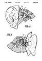
- FIGS. 1 and 2illustrate, respectively, front and rear views of the human ear with one form of the invention implanted therein;
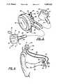
- FIG. 3is a detailed perspective view of the invention in one embodiment
- FIG. 4is a schematic view illustrating the invention shown in FIG. 3 in use
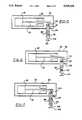
- FIG. 5is a detailed perspective view of the invention in a second embodiment
- FIG. 6is a detailed perspective view of the invention in a third embodiment.
- FIG. 7is a detailed perspective view of the invention in a fourth embodiment.
- the present inventionin a first embodiment, provides an acoustic coupler which may be used for both sound pick up and sound delivery systems.
- FIG. 3illustrates the presently preferred embodiment in a configuration providing both sound pick up and sound delivery systems.
- a sound pick up coupler 10 and a sound delivery coupler 12are illustrated.
- the sound pick up and delivery couplersboth comprise a cylindrical containment member 14 with closed end 16.
- a flexible and compliant diaphragm or membrane 18is stretched across and sealed to the outer circular periphery 20 of containment member 14 to define a sound chamber 22.
- diaphragm 18is fabricated from a 0.10 mm thick film of synthetic rubber material which can be obtained from Dow Corning Company under the brand name Silastic®.
- the diaphragmmay be affixed to periphery 20 using Silastic® Type A adhesive also available from Dow Corning Company.
- the containment memberis of a sufficiently small size to fit within the middle ear cavity, generally as illustrated in FIGS. 1 and 2.
- the presently preferred containment memberhas an outer diameter of 3.00 mm when measured across circular periphery 20.
- the diaphragmis attached to the circular periphery without placing the diaphragm under tension, so that the resulting installed diaphragm is free to flex up and down in the auditory frequency range.
- Containment member 14is provided with a nipple 24 which communicates with sound chamber 22 and which receives the end of a length of tubing 26.
- Tubing 26is coupled at the opposite end to the sound reinforcement and processing package 28, which is preferably located outside the middle ear cavity as illustrated in FIGS. 1 and 2.
- the sound reinforcement and processing package 28is preferably located outside the middle ear cavity as illustrated in FIGS. 1 and 2.
- the presently preferred containment member 14 and tubing 26are air filled, other fluids may be used.
- a wire hook 30can be attached as with adhesive to the center of diaphragm 18.
- the hookis shaped to attach to one of the ossicular bones within the ear and serves to physically couple movement of the ossicular chain to diaphragm 18, to thereby introduce acoustical energy into sound chamber 22, allowing transmission of the acoustic energy through tubing 26 to microphone 36.
- diaphragm 18When used as a sound delivery coupler, such as coupler 12, diaphragm 18 is provided with a disc 32, suitably secured to the diaphragm as with adhesive.
- the discis preferably porous or fibrous material, such as ceramic and is intended to be placed in contact with a selected ossicular bone, the porous nature of the disc permitting tissue to grow into and fuse with the disc.
- the discthereby couples acoustical energy carried by movement of diaphragm 18 to the desired ossicular bone for further processing by the human ear.
- a compliant discmay decrease the restriction of diaphragm movement caused by gluing a ceramic disc in the center.
- the diaphragm 18is positioned within the middle ear either in contact with or behind the tympanic membrane of the ear so that movement of the tympanic membrane imparts a corresponding movement in diaphragm 18 by direct contact in the first case or by sound pressure variations in the entrapped air volume of the middle ear in the second case.
- the porous or fibrous discis the presently preferred means for attachment to the stapes, oval window or other ossicular member
- the diaphragmmay be attached to the stapes using magnets.
- a first magnetis attached to the diaphragm 18, on either the inner surface or the outer surface, and a bumper of ferrous material is adhered to the stapes.
- the magnet and ferrous bumperare attracted to one another by the Newton traction force and create a mechanical coupling between the membrane and the ossicular member.
- Adhesive materialscan also be used to attach the diaphragm directly to the stapes or other ossicular member.
- the sound reinforcement and processing package 28, also illustrated in FIG. 4,preferably comprises a circuit board or substrate 34 to which a miniaturized microphone 36 and hearing aid receiver 38 are attached.
- the microphone and receiverare electrically connected to the desired amplification and signal processing electronic circuitry 40 which may be embodied in integrated circuits surface mounted or otherwise attached to circuit board 34.
- a battery 42(FIG. 3) is secured to and electrically connected to one side of circuit board 34.
- the batteryis rechargeable and the electronic circuitry includes an inductively coupled circuit means 41 for recharging the battery.
- circuit 41includes an electromagnetic coil 44 provided as part of the package 28 (FIG. 3).
- the coilis positioned near the surface of the skin of the patient and forms the secondary windings of a transformer.
- an external coilis placed on or near the skin adjacent the secondary coil 44 forming the primary windings of a transformer.
- the primary and secondary coilsare electromagnetically coupled with one another to form a transformer through which electrical energy is conveyed to charge battery 42.
- microphone 36 and receiver 38are each provided with a fitting 4 which communicates with the interior cavity of the microphone and receiver, respectively.
- a fitting 4which communicates with the interior cavity of the microphone and receiver, respectively.
- two such fittings 46are illustrated, one communicating with the microphone and one communicating with the receiver (both housed within package 28).
- a short length of tubing 48is attached to each fitting and the opposite end of the tubing is fitted with a ceramic plug 49 serving to close the end of the tubing.
- This short length of tubingalong with the sound delivery tube to the chamber and dampers with impedance equal to the characteristic impedance of the tubing, provides a relatively constant acoustical impedance for proper termination of the microphone and receiver units.
- tubing 48provides proper termination of the even harmonics, whereas the tubing 26 connected to the coupler acts as an open-ended tubing, thereby providing a good acoustical match at the odd harmonics.
- tubing 26 connected to the coupleracts as an open-ended tubing, thereby providing a good acoustical match at the odd harmonics.
- a substantially constant acoustical impedanceresults with a sufficiently wide bandwidth for conveying acoustical signals in the human hearing range.
- FIGS. 1 and 2illustrate one use of the invention wherein pick up coupler 10 is attached by means of hook 30 to the malleus 50.
- the delivery coupler 12is attached by means of ceramic disc 32 to the incus end of the stapes 52.
- the ossicular chainis dearticulated by disconnecting two of the ossicular bones, such as at the connection between stapes 52 and incus 54.
- the incus 54may be removed to provide space and so as not to interfere with movement of the stapes now under control of delivery coupler 12.
- Pick up coupler 10is held in place by hooking onto the malleus and delivery coupler 12 is held in place by affixing to a bone pin, or the like, secured to the bone mass adjacent the middle ear cavity.
- the couplersmay be installed by making the appropriate incision and opening behind the ear as illustrated in FIG. 2 at 56. Opening 56 may then be used to receive the sound reinforcement and processing package 28, with either the secondary coil 44 or battery 42 being positioned immediately beneath the
- the acoustic coupler sound pick up and delivery system as illustrated in FIGS. 1 and 2works as follows. Sounds enter the ear canal 58 and impinges upon the tympanic membrane 60, causing it to vibrate. The tympanic membrane, being attached to the malleus 50, thus imparts vibratory movement to the malleus. In a normal ear this movement of the malleus is transmitted through the incus 54 to the stapes. However, since the incus and stapes have been dearticulated, this movement is no longer communicated through to the stapes. Instead, movement of the malleus acts through hook 30 to cause the diaphragm 18 of pick up coupler 10 to vibrate.
- Vibration of the pick up coupler diaphragmcauses changes in the sound pressure levels within the sound chamber 22 of the pick up coupler. These pressure changes are transmitted through tubing 26 to the microphone 36. Microphone 36 converts the sound pressure level changes into electrical signals which are processed by the amplification and signal processing circuitry 40 in accordance with the needs of the particular patient.
- the signalswill be amplified and may be additionally filtered to emphasize or de-emphasize various frequency ranges.
- Either analog or digital processing of the electrical signalscan be employed. For example, if the patient has a profound hearing loss at most speech frequencies but has normal hearing at the low and high end of the human hearing spectrum, then the signal processing would increase the amplitude of signals at the speech frequencies while leaving the remaining frequencies unchanged. Using digital techniques, the electronic signal processing can be quite precise and quite frequency-selective, as needed. The objective of this signal processing is to provide a signal which compensates for deficiencies in the patient's hearing, in an effort to provide as much hearing as is possible.
- the electrical signalis fed to receiver 38 which converts the electrical signals back into sound pressure level changes which are then coupled through the delivery coupler tubing 26 to the delivery coupler 12.
- the sound pressure level changes within delivery coupler 12cause the corresponding diaphragm 18 and ceramic disc 32 to vibrate at an amplitude and frequency corresponding to the amplitude and frequency of the sound waves which entered the ear canal (as modified by the electronic processing). This vibration is transmitted to the stapes which then acts in usual fashion.
- FIGS. 5, 6, and 7illustrate separate embodiments associated with the mechanical coupling of pressure level changes through tube 26 to the stapes.
- a housing 39contains a coil 45 is provided and is made to contain a usual armature 70 which is vertically movable in response to a changing magnetic flux within coil 45.
- armature 70Connected to an end of armature 70 is a generally "T" shaped piston 72 having its expanded horizontal end 74 generally disposed within tube 26.
- a secondary generally “T” shaped piston 76is also provided and has its expanded horizontal end 78 generally disposed within tube 26 while having a cup shaped opposite end 80 arranged such that it is contact with and secured to the stapes.
- Tube 26is filled with very low loss synthetic rubber material 82 such as Silastic® produced by the Dow Corning Company and pistons 72 and 76 are free to move therein.
- material 82such as Silastic® produced by the Dow Corning Company
- piston 72is made to move in and out of tube 26 causing sound pressure level changes therein.
- material 82is transmitted by material 82 to piston 76 which moves in response thereto causing physical transmission of the transmitted pressure changes to the attached stapes.
- Vdenotes calculated velocity
- Ydenotes the aforementioned Young's modulus
- ddenotes the characteristic material density
- the characteristic impedance of the tube 26 of FIG. 5is known to be approximately computed as:
- Z mdenotes the characteristic impedance of tube 26 and which is also determined by the characteristic density and Young's modulus of material 82
- Sdenotes the cross-sectional area of tube 26
- Ydetermines the aforementioned Young's modulus of material 82.
- the characteristic mechanical impedance of the filled tube 26should be approximately 300 dyne-sec/cm as determined from the cross-sectional area of the tube 26 and the density and elasticity of the aforementioned filling material 82 of the embodiment of FIG. 5.
- the tube 26 and pistons 72 and 76are also preferably made of a stainless steel or titanium material.
- FIG. 6Another embodiment of this invention is illustrated in FIG. 6 and utilizes compliant seals 92 and 92 which are mounted to pistons 72 and 76 respectively, and which seal pistons 90 and 92 from tube 26 such that a fluid 94 having lower attenuation characteristics than material 82 of FIG. 5 may be displaced therein. Fluid 94 thusly has the ability to more efficiently transfer generated wave pressures created by armature 70 to the stapes attached to piston 76. It should be noted that pistons 72 and 76 shown in FIGS. 5 and 6 are usually made of stainless steel and that Equations 1-5 and all associated relationships described with reference to the embodiment of FIG. 5 apply equally to the embodiment of FIG. 6.
- FIG. 7Another embodiment of this invention is illustrated in FIG. 7 in which a stainless steel generally hollow tube 100 having a typical length of approximately five to ten millimeters and a typical outside diameter of approximately one-half of a millimeter is disposed.
- Tube 100is shown as having flared end portions 104 and 106 integrally defined thereby with portion 106 having a usually cup shaped portion 108 which attaches to the stapes in substantially the same manner as previously described with reference to portion 80 of piston 76.
- End 104is attached to armature 70 by brazing, or by use of standard epoxy material.
- Tube 26 in combination with tube 100provides a direct coupling of generated pressure waves from armature 70 to portion 108 and subsequently transfers this pressure to the attached stapes thusly greatly increasing the transmission efficiency of all of the embodiments illustrated in FIGS. 5 and 6.
- a fluid or other low loss elastic material 96may further be disposed within tube 26, in addition to member 100, and further act to further increase associated transmission efficiency. Equations 1-5 and all associated relationships developed with reference to the embodiment of FIG. 5 apply equally to the embodiment of FIG. 7 and the previously described advantages associated surgical implantation also apply to the embodiment of FIG. 7 as well.
- the present inventionprovides a solution to the problem of electromechanical transducer placement within the middle ear cavity. While the invention has been illustrated in an application utilizing both a sound pick up and a sound delivery system, the invention may be adapted for other uses as well. For example, if direct stimulation of the cochlea is to be implemented, the sound delivery coupler may be eliminated, with the electrical signals from the sound reinforcement and processing package going directly to a cochlear implant. Accordingly, it should be understood that the present invention is capable of certain modifications without departing from the spirit of the invention as set forth in the appended claims.
Landscapes
- Health & Medical Sciences (AREA)
- General Health & Medical Sciences (AREA)
- Otolaryngology (AREA)
- Neurosurgery (AREA)
- Physics & Mathematics (AREA)
- Engineering & Computer Science (AREA)
- Acoustics & Sound (AREA)
- Signal Processing (AREA)
- Prostheses (AREA)
Abstract
Description
V=(Y/d).sup.1/2 (Equation 1)
Z.sub.m =S(d*Y).sup.1/2 (Equation 2)
L=jw (1×10.sup.-3)+300+(1/jw) (1.2×10.sup.-6) (Equation 3)
F.sub.s /F.sub.a =e.sup.-aL (Equation 4)
a<(1/L) ln (1/0.9) (Equation 5)
Claims (9)
Priority Applications (1)
| Application Number | Priority Date | Filing Date | Title |
|---|---|---|---|
| US07/420,292US5085628A (en) | 1988-09-09 | 1989-10-12 | Implantable hearing aid coupler device |
Applications Claiming Priority (2)
| Application Number | Priority Date | Filing Date | Title |
|---|---|---|---|
| US07/242,365US4988333A (en) | 1988-09-09 | 1988-09-09 | Implantable middle ear hearing aid system and acoustic coupler therefor |
| US07/420,292US5085628A (en) | 1988-09-09 | 1989-10-12 | Implantable hearing aid coupler device |
Related Parent Applications (1)
| Application Number | Title | Priority Date | Filing Date |
|---|---|---|---|
| US07/242,365Continuation-In-PartUS4988333A (en) | 1988-09-09 | 1988-09-09 | Implantable middle ear hearing aid system and acoustic coupler therefor |
Publications (1)
| Publication Number | Publication Date |
|---|---|
| US5085628Atrue US5085628A (en) | 1992-02-04 |
Family
ID=26935034
Family Applications (1)
| Application Number | Title | Priority Date | Filing Date |
|---|---|---|---|
| US07/420,292Expired - LifetimeUS5085628A (en) | 1988-09-09 | 1989-10-12 | Implantable hearing aid coupler device |
Country Status (1)
| Country | Link |
|---|---|
| US (1) | US5085628A (en) |
Cited By (60)
| Publication number | Priority date | Publication date | Assignee | Title |
|---|---|---|---|---|
| US5176620A (en)* | 1990-10-17 | 1993-01-05 | Samuel Gilman | Hearing aid having a liquid transmission means communicative with the cochlea and method of use thereof |
| US5282858A (en)* | 1991-06-17 | 1994-02-01 | American Cyanamid Company | Hermetically sealed implantable transducer |
| WO1995017078A1 (en)* | 1993-12-14 | 1995-06-22 | Hill Frank C | Hearing aid |
| US5456654A (en)* | 1993-07-01 | 1995-10-10 | Ball; Geoffrey R. | Implantable magnetic hearing aid transducer |
| US5531787A (en)* | 1993-01-25 | 1996-07-02 | Lesinski; S. George | Implantable auditory system with micromachined microsensor and microactuator |
| US5554096A (en)* | 1993-07-01 | 1996-09-10 | Symphonix | Implantable electromagnetic hearing transducer |
| US5624376A (en)* | 1993-07-01 | 1997-04-29 | Symphonix Devices, Inc. | Implantable and external hearing systems having a floating mass transducer |
| US5772575A (en)* | 1995-09-22 | 1998-06-30 | S. George Lesinski | Implantable hearing aid |
| US5782744A (en)* | 1995-11-13 | 1998-07-21 | Money; David | Implantable microphone for cochlear implants and the like |
| US5800336A (en)* | 1993-07-01 | 1998-09-01 | Symphonix Devices, Inc. | Advanced designs of floating mass transducers |
| US5859916A (en)* | 1996-07-12 | 1999-01-12 | Symphonix Devices, Inc. | Two stage implantable microphone |
| US5881158A (en)* | 1996-05-24 | 1999-03-09 | United States Surgical Corporation | Microphones for an implantable hearing aid |
| US5888187A (en)* | 1997-03-27 | 1999-03-30 | Symphonix Devices, Inc. | Implantable microphone |
| US5897486A (en)* | 1993-07-01 | 1999-04-27 | Symphonix Devices, Inc. | Dual coil floating mass transducers |
| US5913815A (en)* | 1993-07-01 | 1999-06-22 | Symphonix Devices, Inc. | Bone conducting floating mass transducers |
| US5951601A (en)* | 1996-03-25 | 1999-09-14 | Lesinski; S. George | Attaching an implantable hearing aid microactuator |
| US5977689A (en)* | 1996-07-19 | 1999-11-02 | Neukermans; Armand P. | Biocompatible, implantable hearing aid microactuator |
| US6068589A (en)* | 1996-02-15 | 2000-05-30 | Neukermans; Armand P. | Biocompatible fully implantable hearing aid transducers |
| US6093144A (en)* | 1997-12-16 | 2000-07-25 | Symphonix Devices, Inc. | Implantable microphone having improved sensitivity and frequency response |
| US6108432A (en)* | 1996-12-26 | 2000-08-22 | Citizen Electronics Co., Ltd. | Surface mount electromagnetic sound producing device |
| US6293903B1 (en) | 2000-05-30 | 2001-09-25 | Otologics Llc | Apparatus and method for mounting implantable hearing aid device |
| US6315710B1 (en) | 1997-07-21 | 2001-11-13 | St. Croix Medical, Inc. | Hearing system with middle ear transducer mount |
| US6473651B1 (en) | 1999-03-02 | 2002-10-29 | Advanced Bionics Corporation | Fluid filled microphone balloon to be implanted in the middle ear |
| US6491622B1 (en) | 2000-05-30 | 2002-12-10 | Otologics Llc | Apparatus and method for positioning implantable hearing aid device |
| US6517476B1 (en) | 2000-05-30 | 2003-02-11 | Otologics Llc | Connector for implantable hearing aid |
| US6540662B2 (en) | 1998-06-05 | 2003-04-01 | St. Croix Medical, Inc. | Method and apparatus for reduced feedback in implantable hearing assistance systems |
| US6585637B2 (en)* | 1998-10-15 | 2003-07-01 | St. Croix Medical, Inc. | Method and apparatus for fixation type feedback reduction in implantable hearing assistance systems |
| US20030229262A1 (en)* | 2001-11-20 | 2003-12-11 | Easter James Roy | Apparatus and method for ossicular fixation of implantable hearing aid actuator |
| US6671550B2 (en) | 2000-09-20 | 2003-12-30 | Medtronic, Inc. | System and method for determining location and tissue contact of an implantable medical device within a body |
| US6676592B2 (en) | 1993-07-01 | 2004-01-13 | Symphonix Devices, Inc. | Dual coil floating mass transducers |
| US6689045B2 (en) | 1998-09-24 | 2004-02-10 | St. Croix Medical, Inc. | Method and apparatus for improving signal quality in implantable hearing systems |
| US6705985B2 (en) | 2001-09-28 | 2004-03-16 | Otologics Llc | Apparatus and method for ossicular fixation of implantable hearing aid actuator |
| US6714806B2 (en) | 2000-09-20 | 2004-03-30 | Medtronic, Inc. | System and method for determining tissue contact of an implantable medical device within a body |
| US6726618B2 (en) | 2001-04-12 | 2004-04-27 | Otologics, Llc | Hearing aid with internal acoustic middle ear transducer |
| US6730015B2 (en) | 2001-06-01 | 2004-05-04 | Mike Schugt | Flexible transducer supports |
| US20040264725A1 (en)* | 2003-05-19 | 2004-12-30 | Madsen Clair W. | Hearing aid system and transducer with hermetically sealed housing |
| US6879693B2 (en)* | 2002-02-26 | 2005-04-12 | Otologics, Llc. | Method and system for external assessment of hearing aids that include implanted actuators |
| US20050131272A1 (en)* | 2003-12-11 | 2005-06-16 | Bernd Waldmann | Electrophysiological measurement method and system for positioning an implantable, hearing instrument transducer |
| US20050137447A1 (en)* | 2002-03-21 | 2005-06-23 | Armin Bernhard | Acoustic sensor for an implantable hearing aid |
| US20050203557A1 (en)* | 2001-10-30 | 2005-09-15 | Lesinski S. G. | Implantation method for a hearing aid microactuator implanted into the cochlea |
| US20060058819A1 (en)* | 2004-09-10 | 2006-03-16 | Kasic James F Ii | Adjustable bone bracket |
| US20060247488A1 (en)* | 2005-04-27 | 2006-11-02 | Bernd Waldmann | Implantable hearing aid actuator positioning |
| US20060269076A1 (en)* | 2002-02-26 | 2006-11-30 | Miller Douglas A | Method and system for external assessment of hearing aids that include implanted actuators |
| US20070021647A1 (en)* | 2005-06-20 | 2007-01-25 | Otologics, Llc | Soft tissue placement of implantable microphone |
| US20070083078A1 (en)* | 2005-10-06 | 2007-04-12 | Easter James R | Implantable transducer with transverse force application |
| US20070142697A1 (en)* | 2005-12-16 | 2007-06-21 | Robert Edwin Schneider | Apparatus for connection of implantable devices to the auditory system |
| US7278963B2 (en) | 2003-01-27 | 2007-10-09 | Otologics, Llc | Implantable hearing aid transducer with advanceable actuator to facilitate coupling with the auditory system |
| US20080004486A1 (en)* | 2006-06-14 | 2008-01-03 | Otologics, Llc | Compressive coupling of an implantable hearing aid actuator to an auditory component |
| US20080031465A1 (en)* | 2000-01-20 | 2008-02-07 | Vibrant Med-El Hearing Technology Gmbh | Soundbridge test system |
| US20080051623A1 (en)* | 2003-01-27 | 2008-02-28 | Schneider Robert E | Simplified implantable hearing aid transducer apparatus |
| US20090034769A1 (en)* | 2005-01-27 | 2009-02-05 | Cochlear Limited | Implantable medical device |
| US20090110713A1 (en)* | 2007-10-31 | 2009-04-30 | Florencia Lim | Biodegradable polymeric materials providing controlled release of hydrophobic drugs from implantable devices |
| US20090141919A1 (en)* | 2005-08-22 | 2009-06-04 | 3Win N.V. | Combined set comprising a vibrator actuator and an implantable device |
| US20090187233A1 (en)* | 2008-01-18 | 2009-07-23 | Stracener Steve W | Connector for implantable hearing aid |
| US20090291111A1 (en)* | 2008-05-21 | 2009-11-26 | Florencia Lim | Coating comprising an amorphous primer layer and a semi-crystalline reservoir layer |
| US7676372B1 (en) | 1999-02-16 | 2010-03-09 | Yugen Kaisha Gm&M | Prosthetic hearing device that transforms a detected speech into a speech of a speech form assistive in understanding the semantic meaning in the detected speech |
| US7722525B2 (en) | 2007-05-24 | 2010-05-25 | Otologics, Llc | Lateral coupling of an implantable hearing aid actuator to an auditory component |
| US9090745B2 (en) | 2007-06-29 | 2015-07-28 | Abbott Cardiovascular Systems Inc. | Biodegradable triblock copolymers for implantable devices |
| US9155887B2 (en) | 2010-10-19 | 2015-10-13 | Cochlear Limited | Relay interface for connecting an implanted medical device to an external electronics device |
| US11924374B2 (en) | 2015-09-06 | 2024-03-05 | Cochlear Limited | System for real time, remote access to and adjustment of patient hearing aid with patient in normal life environment |
Citations (27)
| Publication number | Priority date | Publication date | Assignee | Title |
|---|---|---|---|---|
| US622328A (en)* | 1899-04-04 | Magneto ear-phone | ||
| US2702354A (en)* | 1952-02-28 | 1955-02-15 | Astatic Corp | Contact microphone |
| US3346704A (en)* | 1963-12-27 | 1967-10-10 | Jack L Mahoney | Means for aiding hearing |
| US3633217A (en)* | 1969-07-01 | 1972-01-11 | Westinghouse Electric Corp | Electromagnetic energy converter for pulsing an implantable blood pump |
| US3674945A (en)* | 1970-03-11 | 1972-07-04 | Raytheon Co | Acoustic impedance matching system |
| US3676611A (en)* | 1970-03-13 | 1972-07-11 | Erwin E Stephens | Earpiece for hearing aid having sound inlet for high frequencies |
| US3763333A (en)* | 1972-07-24 | 1973-10-02 | Ambitex Co | Acoustic feedback stabilization system particularly suited for hearing aids |
| US3771173A (en)* | 1971-06-09 | 1973-11-13 | Fair J | Artificial heart |
| US3842440A (en)* | 1972-09-01 | 1974-10-22 | E Karlson | Implantable linear motor prosthetic heart and control system therefor |
| US3870832A (en)* | 1972-07-18 | 1975-03-11 | John M Fredrickson | Implantable electromagnetic hearing aid |
| US3882285A (en)* | 1973-10-09 | 1975-05-06 | Vicon Instr Company | Implantable hearing aid and method of improving hearing |
| US3919722A (en)* | 1973-03-06 | 1975-11-18 | Us Health | Totally implantable artificial replacement heart |
| US3974825A (en)* | 1975-10-01 | 1976-08-17 | Baylor College Of Medicine | Remote electrical monitoring of gas activated blood pumps |
| US4143661A (en)* | 1977-12-12 | 1979-03-13 | Andros Incorporated | Power supply for body implant and method for operation |
| US4213207A (en)* | 1978-04-07 | 1980-07-22 | Wilson Frederick M | Artificial heart and method of pumping blood |
| US4251686A (en)* | 1978-12-01 | 1981-02-17 | Sokolich William G | Closed sound delivery system |
| US4357497A (en)* | 1979-09-24 | 1982-11-02 | Hochmair Ingeborg | System for enhancing auditory stimulation and the like |
| US4369530A (en)* | 1981-05-19 | 1983-01-25 | Foxcroft Associates | Hydraulically actuated cardiac prosthesis and method of actuation |
| US4428377A (en)* | 1980-03-06 | 1984-01-31 | Siemens Aktiengesellschaft | Method for the electrical stimulation of the auditory nerve and multichannel hearing prosthesis for carrying out the method |
| US4441210A (en)* | 1981-09-18 | 1984-04-03 | Hochmair Erwin S | Transcutaneous signal transmission system and methods |
| US4542532A (en)* | 1984-03-09 | 1985-09-17 | Medtronic, Inc. | Dual-antenna transceiver |
| US4606329A (en)* | 1985-05-22 | 1986-08-19 | Xomed, Inc. | Implantable electromagnetic middle-ear bone-conduction hearing aid device |
| US4611598A (en)* | 1984-05-30 | 1986-09-16 | Hortmann Gmbh | Multi-frequency transmission system for implanted hearing aids |
| US4662358A (en)* | 1984-04-17 | 1987-05-05 | Thoratec Laboratories Corporation | Electronic control system for a cardiac prosthesis |
| US4665896A (en)* | 1985-07-22 | 1987-05-19 | Novacor Medical Corporation | Power supply for body implant and method of use |
| US4666443A (en)* | 1986-04-18 | 1987-05-19 | Novacor Medical Corporation | Biventricular circulatory assist system and method |
| US4729366A (en)* | 1984-12-04 | 1988-03-08 | Medical Devices Group, Inc. | Implantable hearing aid and method of improving hearing |
- 1989
- 1989-10-12USUS07/420,292patent/US5085628A/ennot_activeExpired - Lifetime
Patent Citations (27)
| Publication number | Priority date | Publication date | Assignee | Title |
|---|---|---|---|---|
| US622328A (en)* | 1899-04-04 | Magneto ear-phone | ||
| US2702354A (en)* | 1952-02-28 | 1955-02-15 | Astatic Corp | Contact microphone |
| US3346704A (en)* | 1963-12-27 | 1967-10-10 | Jack L Mahoney | Means for aiding hearing |
| US3633217A (en)* | 1969-07-01 | 1972-01-11 | Westinghouse Electric Corp | Electromagnetic energy converter for pulsing an implantable blood pump |
| US3674945A (en)* | 1970-03-11 | 1972-07-04 | Raytheon Co | Acoustic impedance matching system |
| US3676611A (en)* | 1970-03-13 | 1972-07-11 | Erwin E Stephens | Earpiece for hearing aid having sound inlet for high frequencies |
| US3771173A (en)* | 1971-06-09 | 1973-11-13 | Fair J | Artificial heart |
| US3870832A (en)* | 1972-07-18 | 1975-03-11 | John M Fredrickson | Implantable electromagnetic hearing aid |
| US3763333A (en)* | 1972-07-24 | 1973-10-02 | Ambitex Co | Acoustic feedback stabilization system particularly suited for hearing aids |
| US3842440A (en)* | 1972-09-01 | 1974-10-22 | E Karlson | Implantable linear motor prosthetic heart and control system therefor |
| US3919722A (en)* | 1973-03-06 | 1975-11-18 | Us Health | Totally implantable artificial replacement heart |
| US3882285A (en)* | 1973-10-09 | 1975-05-06 | Vicon Instr Company | Implantable hearing aid and method of improving hearing |
| US3974825A (en)* | 1975-10-01 | 1976-08-17 | Baylor College Of Medicine | Remote electrical monitoring of gas activated blood pumps |
| US4143661A (en)* | 1977-12-12 | 1979-03-13 | Andros Incorporated | Power supply for body implant and method for operation |
| US4213207A (en)* | 1978-04-07 | 1980-07-22 | Wilson Frederick M | Artificial heart and method of pumping blood |
| US4251686A (en)* | 1978-12-01 | 1981-02-17 | Sokolich William G | Closed sound delivery system |
| US4357497A (en)* | 1979-09-24 | 1982-11-02 | Hochmair Ingeborg | System for enhancing auditory stimulation and the like |
| US4428377A (en)* | 1980-03-06 | 1984-01-31 | Siemens Aktiengesellschaft | Method for the electrical stimulation of the auditory nerve and multichannel hearing prosthesis for carrying out the method |
| US4369530A (en)* | 1981-05-19 | 1983-01-25 | Foxcroft Associates | Hydraulically actuated cardiac prosthesis and method of actuation |
| US4441210A (en)* | 1981-09-18 | 1984-04-03 | Hochmair Erwin S | Transcutaneous signal transmission system and methods |
| US4542532A (en)* | 1984-03-09 | 1985-09-17 | Medtronic, Inc. | Dual-antenna transceiver |
| US4662358A (en)* | 1984-04-17 | 1987-05-05 | Thoratec Laboratories Corporation | Electronic control system for a cardiac prosthesis |
| US4611598A (en)* | 1984-05-30 | 1986-09-16 | Hortmann Gmbh | Multi-frequency transmission system for implanted hearing aids |
| US4729366A (en)* | 1984-12-04 | 1988-03-08 | Medical Devices Group, Inc. | Implantable hearing aid and method of improving hearing |
| US4606329A (en)* | 1985-05-22 | 1986-08-19 | Xomed, Inc. | Implantable electromagnetic middle-ear bone-conduction hearing aid device |
| US4665896A (en)* | 1985-07-22 | 1987-05-19 | Novacor Medical Corporation | Power supply for body implant and method of use |
| US4666443A (en)* | 1986-04-18 | 1987-05-19 | Novacor Medical Corporation | Biventricular circulatory assist system and method |
Non-Patent Citations (11)
| Title |
|---|
| Frederickson et al. "Evaluation of an Electromagnetic Implantable Hearing Aid", Jun. 1972. |
| Frederickson et al. Evaluation of an Electromagnetic Implantable Hearing Aid , Jun. 1972.* |
| Goode, "Current Status of Electromagnetic Implantable Hearing Aids", Otolaryngologic Clinics of North America. |
| Goode, Current Status of Electromagnetic Implantable Hearing Aids , Otolaryngologic Clinics of North America.* |
| Hough et al., "Implantable Bone Conduction Hearing Device Audiant Bone Conductor", Ann Otol Rhinol Laryngol 95:1986. |
| Hough et al., "Middle Ear Implantable Hearing Device: On-Going Animal and Human Evaluation" Ann Otol Rhinol Laryngol 97:1988. |
| Hough et al., Implantable Bone Conduction Hearing Device Audiant Bone Conductor , Ann Otol Rhinol Laryngol 95:1986.* |
| Hough et al., Middle Ear Implantable Hearing Device: On Going Animal and Human Evaluation Ann Otol Rhinol Laryngol 97:1988.* |
| IEEE Engineering and Medicine in Biology Magazine, Jun. 1987, p. 37.* |
| Yanagihara et al., "Implantable Hearing Aid", Arch Otolaryngol Head Neck Surgery, vol. 113, Aug. 1987. |
| Yanagihara et al., Implantable Hearing Aid , Arch Otolaryngol Head Neck Surgery, vol. 113, Aug. 1987.* |
Cited By (98)
| Publication number | Priority date | Publication date | Assignee | Title |
|---|---|---|---|---|
| US5176620A (en)* | 1990-10-17 | 1993-01-05 | Samuel Gilman | Hearing aid having a liquid transmission means communicative with the cochlea and method of use thereof |
| US5282858A (en)* | 1991-06-17 | 1994-02-01 | American Cyanamid Company | Hermetically sealed implantable transducer |
| US5531787A (en)* | 1993-01-25 | 1996-07-02 | Lesinski; S. George | Implantable auditory system with micromachined microsensor and microactuator |
| US5984859A (en)* | 1993-01-25 | 1999-11-16 | Lesinski; S. George | Implantable auditory system components and system |
| US6676592B2 (en) | 1993-07-01 | 2004-01-13 | Symphonix Devices, Inc. | Dual coil floating mass transducers |
| US5857958A (en)* | 1993-07-01 | 1999-01-12 | Symphonix Devices, Inc. | Implantable and external hearing systems having a floating mass transducer |
| US5554096A (en)* | 1993-07-01 | 1996-09-10 | Symphonix | Implantable electromagnetic hearing transducer |
| US5624376A (en)* | 1993-07-01 | 1997-04-29 | Symphonix Devices, Inc. | Implantable and external hearing systems having a floating mass transducer |
| US5456654A (en)* | 1993-07-01 | 1995-10-10 | Ball; Geoffrey R. | Implantable magnetic hearing aid transducer |
| US5913815A (en)* | 1993-07-01 | 1999-06-22 | Symphonix Devices, Inc. | Bone conducting floating mass transducers |
| US5897486A (en)* | 1993-07-01 | 1999-04-27 | Symphonix Devices, Inc. | Dual coil floating mass transducers |
| US5800336A (en)* | 1993-07-01 | 1998-09-01 | Symphonix Devices, Inc. | Advanced designs of floating mass transducers |
| US6475134B1 (en) | 1993-07-01 | 2002-11-05 | Symphonix Devices, Inc. | Dual coil floating mass transducers |
| AU686299B2 (en)* | 1993-12-14 | 1998-02-05 | Frank C. Hill | Hearing aid |
| WO1995017078A1 (en)* | 1993-12-14 | 1995-06-22 | Hill Frank C | Hearing aid |
| US5430801A (en)* | 1993-12-14 | 1995-07-04 | Hill; Frank C. | Hearing aid |
| US5772575A (en)* | 1995-09-22 | 1998-06-30 | S. George Lesinski | Implantable hearing aid |
| US5782744A (en)* | 1995-11-13 | 1998-07-21 | Money; David | Implantable microphone for cochlear implants and the like |
| US6068589A (en)* | 1996-02-15 | 2000-05-30 | Neukermans; Armand P. | Biocompatible fully implantable hearing aid transducers |
| US5951601A (en)* | 1996-03-25 | 1999-09-14 | Lesinski; S. George | Attaching an implantable hearing aid microactuator |
| US5881158A (en)* | 1996-05-24 | 1999-03-09 | United States Surgical Corporation | Microphones for an implantable hearing aid |
| US5859916A (en)* | 1996-07-12 | 1999-01-12 | Symphonix Devices, Inc. | Two stage implantable microphone |
| US5977689A (en)* | 1996-07-19 | 1999-11-02 | Neukermans; Armand P. | Biocompatible, implantable hearing aid microactuator |
| US6153966A (en)* | 1996-07-19 | 2000-11-28 | Neukermans; Armand P. | Biocompatible, implantable hearing aid microactuator |
| US6108432A (en)* | 1996-12-26 | 2000-08-22 | Citizen Electronics Co., Ltd. | Surface mount electromagnetic sound producing device |
| US5888187A (en)* | 1997-03-27 | 1999-03-30 | Symphonix Devices, Inc. | Implantable microphone |
| US6174278B1 (en) | 1997-03-27 | 2001-01-16 | Symphonix Devices, Inc. | Implantable Microphone |
| US6315710B1 (en) | 1997-07-21 | 2001-11-13 | St. Croix Medical, Inc. | Hearing system with middle ear transducer mount |
| US6422991B1 (en) | 1997-12-16 | 2002-07-23 | Symphonix Devices, Inc. | Implantable microphone having improved sensitivity and frequency response |
| US7322930B2 (en) | 1997-12-16 | 2008-01-29 | Vibrant Med-El Hearing Technology, Gmbh | Implantable microphone having sensitivity and frequency response |
| US6093144A (en)* | 1997-12-16 | 2000-07-25 | Symphonix Devices, Inc. | Implantable microphone having improved sensitivity and frequency response |
| US20080167516A1 (en)* | 1997-12-16 | 2008-07-10 | Vibrant Med-El | Implantable Microphone Having Sensitivity And Frequency Response |
| US7955250B2 (en) | 1997-12-16 | 2011-06-07 | Med-El Elektromedizinische Geraete Gmbh | Implantable microphone having sensitivity and frequency response |
| US6626822B1 (en) | 1997-12-16 | 2003-09-30 | Symphonix Devices, Inc. | Implantable microphone having improved sensitivity and frequency response |
| US20040039245A1 (en)* | 1997-12-16 | 2004-02-26 | Med-El Medical Electronics | Implantable microphone having sensitivity and frequency response |
| US6540662B2 (en) | 1998-06-05 | 2003-04-01 | St. Croix Medical, Inc. | Method and apparatus for reduced feedback in implantable hearing assistance systems |
| US6755778B2 (en) | 1998-06-05 | 2004-06-29 | St. Croix Medical, Inc. | Method and apparatus for reduced feedback in implantable hearing assistance systems |
| US6689045B2 (en) | 1998-09-24 | 2004-02-10 | St. Croix Medical, Inc. | Method and apparatus for improving signal quality in implantable hearing systems |
| US6585637B2 (en)* | 1998-10-15 | 2003-07-01 | St. Croix Medical, Inc. | Method and apparatus for fixation type feedback reduction in implantable hearing assistance systems |
| US7676372B1 (en) | 1999-02-16 | 2010-03-09 | Yugen Kaisha Gm&M | Prosthetic hearing device that transforms a detected speech into a speech of a speech form assistive in understanding the semantic meaning in the detected speech |
| US6473651B1 (en) | 1999-03-02 | 2002-10-29 | Advanced Bionics Corporation | Fluid filled microphone balloon to be implanted in the middle ear |
| US20080031465A1 (en)* | 2000-01-20 | 2008-02-07 | Vibrant Med-El Hearing Technology Gmbh | Soundbridge test system |
| US7747026B2 (en)* | 2000-01-20 | 2010-06-29 | Vibrant Med-El | Soundbridge test system |
| US6293903B1 (en) | 2000-05-30 | 2001-09-25 | Otologics Llc | Apparatus and method for mounting implantable hearing aid device |
| US6517476B1 (en) | 2000-05-30 | 2003-02-11 | Otologics Llc | Connector for implantable hearing aid |
| US6491622B1 (en) | 2000-05-30 | 2002-12-10 | Otologics Llc | Apparatus and method for positioning implantable hearing aid device |
| US6671550B2 (en) | 2000-09-20 | 2003-12-30 | Medtronic, Inc. | System and method for determining location and tissue contact of an implantable medical device within a body |
| US6714806B2 (en) | 2000-09-20 | 2004-03-30 | Medtronic, Inc. | System and method for determining tissue contact of an implantable medical device within a body |
| US6726618B2 (en) | 2001-04-12 | 2004-04-27 | Otologics, Llc | Hearing aid with internal acoustic middle ear transducer |
| US6730015B2 (en) | 2001-06-01 | 2004-05-04 | Mike Schugt | Flexible transducer supports |
| US6705985B2 (en) | 2001-09-28 | 2004-03-16 | Otologics Llc | Apparatus and method for ossicular fixation of implantable hearing aid actuator |
| US20050203557A1 (en)* | 2001-10-30 | 2005-09-15 | Lesinski S. G. | Implantation method for a hearing aid microactuator implanted into the cochlea |
| US8147544B2 (en) | 2001-10-30 | 2012-04-03 | Otokinetics Inc. | Therapeutic appliance for cochlea |
| US8876689B2 (en) | 2001-10-30 | 2014-11-04 | Otokinetics Inc. | Hearing aid microactuator |
| US20030229262A1 (en)* | 2001-11-20 | 2003-12-11 | Easter James Roy | Apparatus and method for ossicular fixation of implantable hearing aid actuator |
| US6879693B2 (en)* | 2002-02-26 | 2005-04-12 | Otologics, Llc. | Method and system for external assessment of hearing aids that include implanted actuators |
| US7447319B2 (en) | 2002-02-26 | 2008-11-04 | Otologics, Llc | Method and system for external assessment of hearing aids that include implanted actuators |
| US20060269076A1 (en)* | 2002-02-26 | 2006-11-30 | Miller Douglas A | Method and system for external assessment of hearing aids that include implanted actuators |
| US20050137447A1 (en)* | 2002-03-21 | 2005-06-23 | Armin Bernhard | Acoustic sensor for an implantable hearing aid |
| US20080051623A1 (en)* | 2003-01-27 | 2008-02-28 | Schneider Robert E | Simplified implantable hearing aid transducer apparatus |
| US7278963B2 (en) | 2003-01-27 | 2007-10-09 | Otologics, Llc | Implantable hearing aid transducer with advanceable actuator to facilitate coupling with the auditory system |
| US7905824B2 (en) | 2003-01-27 | 2011-03-15 | Otologics, Llc | Implantable hearing aid transducer with advanceable actuator to faciliate coupling with the auditory system |
| US8366601B2 (en) | 2003-01-27 | 2013-02-05 | Cochlear Limited | Simplified implantable hearing aid transducer apparatus |
| US20080249351A1 (en)* | 2003-01-27 | 2008-10-09 | Robert Edwin Schneider | Implantable hearing aid transducer with advanceable actuator to faciliate coupling with the auditory system |
| US20070055092A1 (en)* | 2003-03-20 | 2007-03-08 | Easter James R | Apparatus and method for ossicular fixation of implantable hearing aid actuator |
| WO2004086809A3 (en)* | 2003-03-20 | 2005-09-15 | Otologics Llc | Improved apparatus and method for ossicular fixation of implantable hearing aid actuator |
| US7524278B2 (en)* | 2003-05-19 | 2009-04-28 | Envoy Medical Corporation | Hearing aid system and transducer with hermetically sealed housing |
| US20040264725A1 (en)* | 2003-05-19 | 2004-12-30 | Madsen Clair W. | Hearing aid system and transducer with hermetically sealed housing |
| US20050131272A1 (en)* | 2003-12-11 | 2005-06-16 | Bernd Waldmann | Electrophysiological measurement method and system for positioning an implantable, hearing instrument transducer |
| US7137946B2 (en) | 2003-12-11 | 2006-11-21 | Otologics Llc | Electrophysiological measurement method and system for positioning an implantable, hearing instrument transducer |
| US7326171B2 (en) | 2004-09-10 | 2008-02-05 | Otologics, Llc | Adjustable bone bracket |
| US20060058819A1 (en)* | 2004-09-10 | 2006-03-16 | Kasic James F Ii | Adjustable bone bracket |
| US20090034769A1 (en)* | 2005-01-27 | 2009-02-05 | Cochlear Limited | Implantable medical device |
| US8885837B2 (en)* | 2005-01-27 | 2014-11-11 | Cochlear Limited | Implantable medical device |
| US7582052B2 (en) | 2005-04-27 | 2009-09-01 | Otologics, Llc | Implantable hearing aid actuator positioning |
| US20060247488A1 (en)* | 2005-04-27 | 2006-11-02 | Bernd Waldmann | Implantable hearing aid actuator positioning |
| US20080234539A1 (en)* | 2005-06-20 | 2008-09-25 | William Howard Slattery | Soft tissue placement of implantable microphone |
| US20070021647A1 (en)* | 2005-06-20 | 2007-01-25 | Otologics, Llc | Soft tissue placement of implantable microphone |
| US7354394B2 (en)* | 2005-06-20 | 2008-04-08 | Otologics, Llc | Soft tissue placement of implantable microphone |
| US8184840B2 (en)* | 2005-08-22 | 2012-05-22 | 3Win N.V. | Combined set comprising a vibrator actuator and an implantable device |
| US20090141919A1 (en)* | 2005-08-22 | 2009-06-04 | 3Win N.V. | Combined set comprising a vibrator actuator and an implantable device |
| US7753838B2 (en) | 2005-10-06 | 2010-07-13 | Otologics, Llc | Implantable transducer with transverse force application |
| US20070083078A1 (en)* | 2005-10-06 | 2007-04-12 | Easter James R | Implantable transducer with transverse force application |
| US20070142697A1 (en)* | 2005-12-16 | 2007-06-21 | Robert Edwin Schneider | Apparatus for connection of implantable devices to the auditory system |
| US20080004486A1 (en)* | 2006-06-14 | 2008-01-03 | Otologics, Llc | Compressive coupling of an implantable hearing aid actuator to an auditory component |
| US7722525B2 (en) | 2007-05-24 | 2010-05-25 | Otologics, Llc | Lateral coupling of an implantable hearing aid actuator to an auditory component |
| US9090745B2 (en) | 2007-06-29 | 2015-07-28 | Abbott Cardiovascular Systems Inc. | Biodegradable triblock copolymers for implantable devices |
| US9468707B2 (en) | 2007-06-29 | 2016-10-18 | Abbott Cardiovascular Systems Inc. | Biodegradable triblock copolymers for implantable devices |
| US20090110713A1 (en)* | 2007-10-31 | 2009-04-30 | Florencia Lim | Biodegradable polymeric materials providing controlled release of hydrophobic drugs from implantable devices |
| US7822479B2 (en) | 2008-01-18 | 2010-10-26 | Otologics, Llc | Connector for implantable hearing aid |
| US20090187233A1 (en)* | 2008-01-18 | 2009-07-23 | Stracener Steve W | Connector for implantable hearing aid |
| US8661630B2 (en) | 2008-05-21 | 2014-03-04 | Abbott Cardiovascular Systems Inc. | Coating comprising an amorphous primer layer and a semi-crystalline reservoir layer |
| US20090291111A1 (en)* | 2008-05-21 | 2009-11-26 | Florencia Lim | Coating comprising an amorphous primer layer and a semi-crystalline reservoir layer |
| US9592323B2 (en) | 2008-05-21 | 2017-03-14 | Abbott Cardiovascular Systems Inc. | Coating comprising an amorphous primer layer and a semi-crystalline reservoir layer |
| US9155887B2 (en) | 2010-10-19 | 2015-10-13 | Cochlear Limited | Relay interface for connecting an implanted medical device to an external electronics device |
| US10485974B2 (en) | 2010-10-19 | 2019-11-26 | Cochlear Limited | Relay interface for connecting an implanted medical device to an external electronics device |
| US11376442B2 (en)* | 2010-10-19 | 2022-07-05 | Cochlear Limited | Relay interface for connecting an implanted medical device to an external electronics device |
| US11924374B2 (en) | 2015-09-06 | 2024-03-05 | Cochlear Limited | System for real time, remote access to and adjustment of patient hearing aid with patient in normal life environment |
Similar Documents
| Publication | Publication Date | Title |
|---|---|---|
| US5085628A (en) | Implantable hearing aid coupler device | |
| US4988333A (en) | Implantable middle ear hearing aid system and acoustic coupler therefor | |
| CA2071240C (en) | Hermetically sealed implantable transducer | |
| US6726618B2 (en) | Hearing aid with internal acoustic middle ear transducer | |
| US12133054B2 (en) | Devices and methods for hearing | |
| US10129660B2 (en) | Implantable middle ear transducer having improved frequency response | |
| US8216123B2 (en) | Implantable middle ear hearing device having tubular vibration transducer to drive round window | |
| US6137889A (en) | Direct tympanic membrane excitation via vibrationally conductive assembly | |
| US6010532A (en) | Dual path implantable hearing assistance device | |
| US5176620A (en) | Hearing aid having a liquid transmission means communicative with the cochlea and method of use thereof | |
| US5842967A (en) | Contactless transducer stimulation and sensing of ossicular chain | |
| US5762583A (en) | Piezoelectric film transducer | |
| FI93507C (en) | Device for use in a hearing impaired subject | |
| US6261224B1 (en) | Piezoelectric film transducer for cochlear prosthetic | |
| US5836863A (en) | Hearing aid transducer support | |
| US5993376A (en) | Electromagnetic input transducers for middle ear sensing | |
| US5997466A (en) | Implantable hearing system having multiple transducers | |
| US6214046B1 (en) | Method of implanting an implantable hearing assistance device with remote electronics unit | |
| JPS61273100A (en) | Hearing aid | |
| US7651460B2 (en) | Totally implantable hearing system |
Legal Events
| Date | Code | Title | Description |
|---|---|---|---|
| AS | Assignment | Owner name:STORZ INSTRUMENT COMPANY, 3365 TREE COURT INDUSTRI Free format text:ASSIGNMENT OF ASSIGNORS INTEREST.;ASSIGNORS:ENGEBRETSON, A. MAYNARD;FREDRICKSON, JOHN;REEL/FRAME:005158/0605 Effective date:19891003 | |
| FEPP | Fee payment procedure | Free format text:PAYOR NUMBER ASSIGNED (ORIGINAL EVENT CODE: ASPN); ENTITY STATUS OF PATENT OWNER: SMALL ENTITY | |
| STCF | Information on status: patent grant | Free format text:PATENTED CASE | |
| CC | Certificate of correction | ||
| FPAY | Fee payment | Year of fee payment:4 | |
| REMI | Maintenance fee reminder mailed | ||
| FEPP | Fee payment procedure | Free format text:PAT HOLDER CLAIMS SMALL ENTITY STATUS - SMALL BUSINESS (ORIGINAL EVENT CODE: SM02); ENTITY STATUS OF PATENT OWNER: SMALL ENTITY | |
| FPAY | Fee payment | Year of fee payment:8 | |
| SULP | Surcharge for late payment | ||
| AS | Assignment | Owner name:OTOLOGICS L.L.C., COLORADO Free format text:ASSIGNMENT OF ASSIGNORS INTEREST;ASSIGNOR:OTOLOGICS, INC.;REEL/FRAME:010655/0129 Effective date:19980511 Owner name:OTOLOGICS, INC., COLORADO Free format text:ASSIGNMENT OF ASSIGNORS INTEREST;ASSIGNOR:STORZ INSTRUMENT COMPANY;REEL/FRAME:010655/0143 Effective date:19960331 | |
| AS | Assignment | Owner name:OTOLOGICS, LLC, COLORADO Free format text:ASSIGNMENT OF ASSIGNORS INTEREST;ASSIGNOR:OTOLOGICS, INC.;REEL/FRAME:011461/0847 Effective date:19980511 Owner name:OTOLOGICS, INC., COLORADO Free format text:ASSIGNMENT OF ASSIGNORS INTEREST;ASSIGNOR:STORZ INSTRUMENT COMPANY;REEL/FRAME:011467/0342 Effective date:19960531 | |
| REMI | Maintenance fee reminder mailed | ||
| FPAY | Fee payment | Year of fee payment:12 | |
| SULP | Surcharge for late payment | Year of fee payment:11 | |
| AS | Assignment | Owner name:OLSETH FAMILY GRANDCHIDREN'S EDUCATIONAL TRUST, MI Free format text:SECURITY INTEREST;ASSIGNOR:OTOLOGICS, LLC;REEL/FRAME:016745/0587 Effective date:20050609 Owner name:WARDEN, RICHARD H., MINNESOTA Free format text:SECURITY INTEREST;ASSIGNOR:OTOLOGICS, LLC;REEL/FRAME:016745/0587 Effective date:20050609 Owner name:OBERMAN, LAWRENCE A., ILLINOIS Free format text:SECURITY INTEREST;ASSIGNOR:OTOLOGICS, LLC;REEL/FRAME:016745/0587 Effective date:20050609 Owner name:MEYER, GERALD L., MONTANA Free format text:SECURITY INTEREST;ASSIGNOR:OTOLOGICS, LLC;REEL/FRAME:016745/0587 Effective date:20050609 Owner name:BOEHNEN, DAVID L., MINNESOTA Free format text:SECURITY INTEREST;ASSIGNOR:OTOLOGICS, LLC;REEL/FRAME:016745/0587 Effective date:20050609 Owner name:WAYNE & ROGNLIN, MARLENE, WASHINGTON Free format text:SECURITY INTEREST;ASSIGNOR:OTOLOGICS, LLC;REEL/FRAME:016745/0587 Effective date:20050609 Owner name:RAHN, NOEL P., MINNESOTA Free format text:SECURITY INTEREST;ASSIGNOR:OTOLOGICS, LLC;REEL/FRAME:016745/0587 Effective date:20050609 Owner name:FRISWOLD, FRED R., MINNESOTA Free format text:SECURITY INTEREST;ASSIGNOR:OTOLOGICS, LLC;REEL/FRAME:016745/0587 Effective date:20050609 Owner name:KEOUGH, STEVEN J., MINNESOTA Free format text:SECURITY INTEREST;ASSIGNOR:OTOLOGICS, LLC;REEL/FRAME:016745/0587 Effective date:20050609 Owner name:LEWIS, JR., HARRY T., COLORADO Free format text:SECURITY INTEREST;ASSIGNOR:OTOLOGICS, LLC;REEL/FRAME:016745/0587 Effective date:20050609 Owner name:JOSPEY FAMILY LIMITED PARTNERSHIP, FLORIDA Free format text:SECURITY INTEREST;ASSIGNOR:OTOLOGICS, LLC;REEL/FRAME:016745/0587 Effective date:20050609 Owner name:LINDAHL, DENNIS M., MINNESOTA Free format text:SECURITY INTEREST;ASSIGNOR:OTOLOGICS, LLC;REEL/FRAME:016745/0587 Effective date:20050609 Owner name:STEVEN J. & ZAWADSKI, BARBARA B., MINNESOTA Free format text:SECURITY INTEREST;ASSIGNOR:OTOLOGICS, LLC;REEL/FRAME:016745/0587 Effective date:20050609 Owner name:TOWNSEND, GEORGE, MINNESOTA Free format text:SECURITY INTEREST;ASSIGNOR:OTOLOGICS, LLC;REEL/FRAME:016745/0587 Effective date:20050609 Owner name:DEAN BELBAS, TRUSTEE OF THE DEAN BELBAS REVOCABLE Free format text:SECURITY INTEREST;ASSIGNOR:OTOLOGICS, LLC;REEL/FRAME:016745/0587 Effective date:20050609 Owner name:PETER E. & OBERMEYER, JUDITH C., MINNESOTA Free format text:SECURITY INTEREST;ASSIGNOR:OTOLOGICS, LLC;REEL/FRAME:016745/0587 Effective date:20050609 Owner name:LENZ, WILLIAM & JAMISON-LENZ, PAMELA, MINNESOTA Free format text:SECURITY INTEREST;ASSIGNOR:OTOLOGICS, LLC;REEL/FRAME:016745/0587 Effective date:20050609 Owner name:KRISTO, STEVEN J., WISCONSIN Free format text:SECURITY INTEREST;ASSIGNOR:OTOLOGICS, LLC;REEL/FRAME:016745/0587 Effective date:20050609 Owner name:OLSETH, DALE R., MINNESOTA Free format text:SECURITY INTEREST;ASSIGNOR:OTOLOGICS, LLC;REEL/FRAME:016745/0587 Effective date:20050609 Owner name:MCFARLAND, RICHARD D., MINNESOTA Free format text:SECURITY INTEREST;ASSIGNOR:OTOLOGICS, LLC;REEL/FRAME:016745/0587 Effective date:20050609 Owner name:BRENT & KAREN BLACKEY, MINNESOTA Free format text:SECURITY INTEREST;ASSIGNOR:OTOLOGICS, LLC;REEL/FRAME:016745/0587 Effective date:20050609 Owner name:YOST PARTNERSHIP, L.P., ILLINOIS Free format text:SECURITY INTEREST;ASSIGNOR:OTOLOGICS, LLC;REEL/FRAME:016745/0587 Effective date:20050609 Owner name:ALFRED & ROSE ERICKSON TRUST, MINNESOTA Free format text:SECURITY INTEREST;ASSIGNOR:OTOLOGICS, LLC;REEL/FRAME:016745/0587 Effective date:20050609 Owner name:KAY L. HARDY LIVING TRUST, MONTANA Free format text:SECURITY INTEREST;ASSIGNOR:OTOLOGICS, LLC;REEL/FRAME:016745/0587 Effective date:20050609 Owner name:KING, JOHN J., ARIZONA Free format text:SECURITY INTEREST;ASSIGNOR:OTOLOGICS, LLC;REEL/FRAME:016745/0587 Effective date:20050609 Owner name:AFFINITY VENTURES III, L.P., MINNESOTA Free format text:SECURITY INTEREST;ASSIGNOR:OTOLOGICS, LLC;REEL/FRAME:016745/0587 Effective date:20050609 Owner name:STERLING TRUST COMPANY, CUSTODIAN, TEXAS Free format text:SECURITY INTEREST;ASSIGNOR:OTOLOGICS, LLC;REEL/FRAME:016745/0587 Effective date:20050609 Owner name:TSCHETTER, RONALD A., MONTANA Free format text:SECURITY INTEREST;ASSIGNOR:OTOLOGICS, LLC;REEL/FRAME:016745/0587 Effective date:20050609 Owner name:D&R INVESTMENT PARTNERSHIP, MINNESOTA Free format text:SECURITY INTEREST;ASSIGNOR:OTOLOGICS, LLC;REEL/FRAME:016745/0587 Effective date:20050609 Owner name:RICHARD D. CRAMER REVOCABLE TRUST, MINNESOTA Free format text:SECURITY INTEREST;ASSIGNOR:OTOLOGICS, LLC;REEL/FRAME:016745/0587 Effective date:20050609 Owner name:LESTER J. & SWENSON, DARLENE K., MINNESOTA Free format text:SECURITY INTEREST;ASSIGNOR:OTOLOGICS, LLC;REEL/FRAME:016745/0587 Effective date:20050609 Owner name:TRIGRAN INVESTMENTS, INC., ILLINOIS Free format text:SECURITY INTEREST;ASSIGNOR:OTOLOGICS, LLC;REEL/FRAME:016745/0587 Effective date:20050609 Owner name:LES HARDY, JR. LIVING TRUST, MONTANA Free format text:SECURITY INTEREST;ASSIGNOR:OTOLOGICS, LLC;REEL/FRAME:016745/0587 Effective date:20050609 Owner name:JOHN A. & MESLOW, KAREN J., MINNESOTA Free format text:SECURITY INTEREST;ASSIGNOR:OTOLOGICS, LLC;REEL/FRAME:016745/0587 Effective date:20050609 Owner name:GRANAT, ELIZABETH W., COLORADO Free format text:SECURITY INTEREST;ASSIGNOR:OTOLOGICS, LLC;REEL/FRAME:016745/0587 Effective date:20050609 Owner name:DORSEY R. GARDNER 2002 TRUST, MASSACHUSETTS Free format text:SECURITY INTEREST;ASSIGNOR:OTOLOGICS, LLC;REEL/FRAME:016745/0587 Effective date:20050609 Owner name:KING, MAUREEN, ARIZONA Free format text:SECURITY INTEREST;ASSIGNOR:OTOLOGICS, LLC;REEL/FRAME:016745/0587 Effective date:20050609 Owner name:BR DIRECT MARKETING, CALIFORNIA Free format text:SECURITY INTEREST;ASSIGNOR:OTOLOGICS, LLC;REEL/FRAME:016745/0587 Effective date:20050609 Owner name:KENNETH & NANCY J. GRANAT, ARIZONA Free format text:SECURITY INTEREST;ASSIGNOR:OTOLOGICS, LLC;REEL/FRAME:016745/0587 Effective date:20050609 Owner name:JOHN & CARLYN BRYNGELSON, COLORADO Free format text:SECURITY INTEREST;ASSIGNOR:OTOLOGICS, LLC;REEL/FRAME:016745/0587 Effective date:20050609 Owner name:JERRY & JANE GARBUTT, MISSOURI Free format text:SECURITY INTEREST;ASSIGNOR:OTOLOGICS, LLC;REEL/FRAME:016745/0587 Effective date:20050609 Owner name:PIPER JAFFREY AS CUSTODIAN, MINNESOTA Free format text:SECURITY INTEREST;ASSIGNOR:OTOLOGICS, LLC;REEL/FRAME:016745/0587 Effective date:20050609 Owner name:DACK CATTLE TRUST, COLORADO Free format text:SECURITY INTEREST;ASSIGNOR:OTOLOGICS, LLC;REEL/FRAME:016745/0587 Effective date:20050609 Owner name:PATRICK A. & SMITH, KAREN D., MISSOURI Free format text:SECURITY INTEREST;ASSIGNOR:OTOLOGICS, LLC;REEL/FRAME:016745/0587 Effective date:20050609 Owner name:INSULA PROPERTIES, LLC, MISSOURI Free format text:SECURITY INTEREST;ASSIGNOR:OTOLOGICS, LLC;REEL/FRAME:016745/0587 Effective date:20050609 | |
| AS | Assignment | Owner name:OLSETH FAMILY GRANDCHILDREN'S EDUCATIONAL TRUST, M Free format text:THIRD AMENDMENT TO SECURITY AGREEMENT AND SECURITY AGREEMENT;ASSIGNOR:OTOLOGIC, LLC;REEL/FRAME:019000/0443 Effective date:20060131 Owner name:KING, JERRY & MARTHA, MISSOURI Free format text:THIRD AMENDMENT TO SECURITY AGREEMENT AND SECURITY AGREEMENT;ASSIGNOR:OTOLOGIC, LLC;REEL/FRAME:019000/0443 Effective date:20060131 Owner name:DACK CATTLE TRUST, COLORADO Free format text:THIRD AMENDMENT TO SECURITY AGREEMENT AND SECURITY AGREEMENT;ASSIGNOR:OTOLOGIC, LLC;REEL/FRAME:019000/0443 Effective date:20060131 Owner name:STERLING TRUST COMPANY, CUSTODIAN, TEXAS Free format text:THIRD AMENDMENT TO SECURITY AGREEMENT AND SECURITY AGREEMENT;ASSIGNOR:OTOLOGIC, LLC;REEL/FRAME:019000/0443 Effective date:20060131 Owner name:LEWIS, HARRY T., JR., COLORADO Free format text:THIRD AMENDMENT TO SECURITY AGREEMENT AND SECURITY AGREEMENT;ASSIGNOR:OTOLOGIC, LLC;REEL/FRAME:019000/0443 Effective date:20060131 Owner name:PIPER JAFFREY AS CUSTODIAN, MINNESOTA Free format text:THIRD AMENDMENT TO SECURITY AGREEMENT AND SECURITY AGREEMENT;ASSIGNOR:OTOLOGIC, LLC;REEL/FRAME:019000/0443 Effective date:20060131 Owner name:MELROSE, KENDRICK, MINNESOTA Free format text:THIRD AMENDMENT TO SECURITY AGREEMENT AND SECURITY AGREEMENT;ASSIGNOR:OTOLOGIC, LLC;REEL/FRAME:019000/0443 Effective date:20060131 Owner name:KING, MAUREEN, ARIZONA Free format text:THIRD AMENDMENT TO SECURITY AGREEMENT AND SECURITY AGREEMENT;ASSIGNOR:OTOLOGIC, LLC;REEL/FRAME:019000/0443 Effective date:20060131 Owner name:S. ALBERT D. HANSER, TRUSTEE FOR S. ALBERT D. HANS Free format text:THIRD AMENDMENT TO SECURITY AGREEMENT AND SECURITY AGREEMENT;ASSIGNOR:OTOLOGIC, LLC;REEL/FRAME:019000/0443 Effective date:20060131 Owner name:LINDAHL, DENNIS M., MINNESOTA Free format text:THIRD AMENDMENT TO SECURITY AGREEMENT AND SECURITY AGREEMENT;ASSIGNOR:OTOLOGIC, LLC;REEL/FRAME:019000/0443 Effective date:20060131 Owner name:ILLANES, EDUARDO AND DIANE, COLORADO Free format text:THIRD AMENDMENT TO SECURITY AGREEMENT AND SECURITY AGREEMENT;ASSIGNOR:OTOLOGIC, LLC;REEL/FRAME:019000/0443 Effective date:20060131 Owner name:KAY L. HARDY LIVING TRUST, MONTANA Free format text:THIRD AMENDMENT TO SECURITY AGREEMENT AND SECURITY AGREEMENT;ASSIGNOR:OTOLOGIC, LLC;REEL/FRAME:019000/0443 Effective date:20060131 Owner name:AFFINITY VENTURES III, L.P., MINNESOTA Free format text:THIRD AMENDMENT TO SECURITY AGREEMENT AND SECURITY AGREEMENT;ASSIGNOR:OTOLOGIC, LLC;REEL/FRAME:019000/0443 Effective date:20060131 Owner name:ROGNLIN, WAYNE & MARLENE, WASHINGTON Free format text:THIRD AMENDMENT TO SECURITY AGREEMENT AND SECURITY AGREEMENT;ASSIGNOR:OTOLOGIC, LLC;REEL/FRAME:019000/0443 Effective date:20060131 Owner name:OBERMAN, LAWRENCE A., ILLINOIS Free format text:THIRD AMENDMENT TO SECURITY AGREEMENT AND SECURITY AGREEMENT;ASSIGNOR:OTOLOGIC, LLC;REEL/FRAME:019000/0443 Effective date:20060131 Owner name:ALFRED & ROSE ERICKSON TRUST, MINNESOTA Free format text:THIRD AMENDMENT TO SECURITY AGREEMENT AND SECURITY AGREEMENT;ASSIGNOR:OTOLOGIC, LLC;REEL/FRAME:019000/0443 Effective date:20060131 Owner name:GRANAT, ELIZABETH W., COLORADO Free format text:THIRD AMENDMENT TO SECURITY AGREEMENT AND SECURITY AGREEMENT;ASSIGNOR:OTOLOGIC, LLC;REEL/FRAME:019000/0443 Effective date:20060131 Owner name:KING, JOHN J., ARIZONA Free format text:THIRD AMENDMENT TO SECURITY AGREEMENT AND SECURITY AGREEMENT;ASSIGNOR:OTOLOGIC, LLC;REEL/FRAME:019000/0443 Effective date:20060131 Owner name:COBORN, CHRISTOPHER, MINNESOTA Free format text:THIRD AMENDMENT TO SECURITY AGREEMENT AND SECURITY AGREEMENT;ASSIGNOR:OTOLOGIC, LLC;REEL/FRAME:019000/0443 Effective date:20060131 Owner name:JOSPEY FAMILY LIMITED PARTNERSHIP, FLORIDA Free format text:THIRD AMENDMENT TO SECURITY AGREEMENT AND SECURITY AGREEMENT;ASSIGNOR:OTOLOGIC, LLC;REEL/FRAME:019000/0443 Effective date:20060131 Owner name:TSCHETTER, RONALD A., MONTANA Free format text:THIRD AMENDMENT TO SECURITY AGREEMENT AND SECURITY AGREEMENT;ASSIGNOR:OTOLOGIC, LLC;REEL/FRAME:019000/0443 Effective date:20060131 Owner name:MESLOW, JOHN A. & KAREN J., MINNESOTA Free format text:THIRD AMENDMENT TO SECURITY AGREEMENT AND SECURITY AGREEMENT;ASSIGNOR:OTOLOGIC, LLC;REEL/FRAME:019000/0443 Effective date:20060131 Owner name:ZAWADSKI, STEVEN J. & BARBARA B., MINNESOTA Free format text:THIRD AMENDMENT TO SECURITY AGREEMENT AND SECURITY AGREEMENT;ASSIGNOR:OTOLOGIC, LLC;REEL/FRAME:019000/0443 Effective date:20060131 Owner name:BR DIRECT MARKETING, CALIFORNIA Free format text:THIRD AMENDMENT TO SECURITY AGREEMENT AND SECURITY AGREEMENT;ASSIGNOR:OTOLOGIC, LLC;REEL/FRAME:019000/0443 Effective date:20060131 Owner name:KRISTO, STEVEN J., WISCONSIN Free format text:THIRD AMENDMENT TO SECURITY AGREEMENT AND SECURITY AGREEMENT;ASSIGNOR:OTOLOGIC, LLC;REEL/FRAME:019000/0443 Effective date:20060131 Owner name:RAHN, NOEL P., MINNESOTA Free format text:THIRD AMENDMENT TO SECURITY AGREEMENT AND SECURITY AGREEMENT;ASSIGNOR:OTOLOGIC, LLC;REEL/FRAME:019000/0443 Effective date:20060131 Owner name:YOST PARTNERSHIP, L.P., ILLINOIS Free format text:THIRD AMENDMENT TO SECURITY AGREEMENT AND SECURITY AGREEMENT;ASSIGNOR:OTOLOGIC, LLC;REEL/FRAME:019000/0443 Effective date:20060131 Owner name:HANSER, LAURA H., FLORIDA Free format text:THIRD AMENDMENT TO SECURITY AGREEMENT AND SECURITY AGREEMENT;ASSIGNOR:OTOLOGIC, LLC;REEL/FRAME:019000/0443 Effective date:20060131 Owner name:SMITH, PATRICK A. & KAREN D., MISSOURI Free format text:THIRD AMENDMENT TO SECURITY AGREEMENT AND SECURITY AGREEMENT;ASSIGNOR:OTOLOGIC, LLC;REEL/FRAME:019000/0443 Effective date:20060131 Owner name:OBERMEYER, PETER E. & JUDITH C., MINNESOTA Free format text:THIRD AMENDMENT TO SECURITY AGREEMENT AND SECURITY AGREEMENT;ASSIGNOR:OTOLOGIC, LLC;REEL/FRAME:019000/0443 Effective date:20060131 Owner name:SOLON, VLASIE, SR., MINNESOTA Free format text:THIRD AMENDMENT TO SECURITY AGREEMENT AND SECURITY AGREEMENT;ASSIGNOR:OTOLOGIC, LLC;REEL/FRAME:019000/0443 Effective date:20060131 Owner name:OLSETH, DALE R., MINNESOTA Free format text:THIRD AMENDMENT TO SECURITY AGREEMENT AND SECURITY AGREEMENT;ASSIGNOR:OTOLOGIC, LLC;REEL/FRAME:019000/0443 Effective date:20060131 Owner name:RICHARD D. CRAMER REVOCABLE TRUST, MINNESOTA Free format text:THIRD AMENDMENT TO SECURITY AGREEMENT AND SECURITY AGREEMENT;ASSIGNOR:OTOLOGIC, LLC;REEL/FRAME:019000/0443 Effective date:20060131 Owner name:KEOUGH, STEVEN J., MINNESOTA Free format text:THIRD AMENDMENT TO SECURITY AGREEMENT AND SECURITY AGREEMENT;ASSIGNOR:OTOLOGIC, LLC;REEL/FRAME:019000/0443 Effective date:20060131 Owner name:GRANAT, KENNETH & NANCY J., ARIZONA Free format text:THIRD AMENDMENT TO SECURITY AGREEMENT AND SECURITY AGREEMENT;ASSIGNOR:OTOLOGIC, LLC;REEL/FRAME:019000/0443 Effective date:20060131 Owner name:WARDEN, RICHARD H., MINNESOTA Free format text:THIRD AMENDMENT TO SECURITY AGREEMENT AND SECURITY AGREEMENT;ASSIGNOR:OTOLOGIC, LLC;REEL/FRAME:019000/0443 Effective date:20060131 Owner name:THE LYNCH FOUNDATION, MASSACHUSETTS Free format text:THIRD AMENDMENT TO SECURITY AGREEMENT AND SECURITY AGREEMENT;ASSIGNOR:OTOLOGIC, LLC;REEL/FRAME:019000/0443 Effective date:20060131 Owner name:S. ALBERT D. HANSER, TRUSTEE FOR SALLY DODGE HANSE Free format text:THIRD AMENDMENT TO SECURITY AGREEMENT AND SECURITY AGREEMENT;ASSIGNOR:OTOLOGIC, LLC;REEL/FRAME:019000/0443 Effective date:20060131 Owner name:BLACKEY, BRENT & KAREN, MINNESOTA Free format text:THIRD AMENDMENT TO SECURITY AGREEMENT AND SECURITY AGREEMENT;ASSIGNOR:OTOLOGIC, LLC;REEL/FRAME:019000/0443 Effective date:20060131 Owner name:D&R INVESTMENT PARTNERSHIP, MINNESOTA Free format text:THIRD AMENDMENT TO SECURITY AGREEMENT AND SECURITY AGREEMENT;ASSIGNOR:OTOLOGIC, LLC;REEL/FRAME:019000/0443 Effective date:20060131 Owner name:DORSEY R. GARDNER 2002 TRUST, MASSACHUSETTS Free format text:THIRD AMENDMENT TO SECURITY AGREEMENT AND SECURITY AGREEMENT;ASSIGNOR:OTOLOGIC, LLC;REEL/FRAME:019000/0443 Effective date:20060131 Owner name:FRISWOLD, FRED R., MINNESOTA Free format text:THIRD AMENDMENT TO SECURITY AGREEMENT AND SECURITY AGREEMENT;ASSIGNOR:OTOLOGIC, LLC;REEL/FRAME:019000/0443 Effective date:20060131 Owner name:HANSER, ALBERT, III, MASSACHUSETTS Free format text:THIRD AMENDMENT TO SECURITY AGREEMENT AND SECURITY AGREEMENT;ASSIGNOR:OTOLOGIC, LLC;REEL/FRAME:019000/0443 Effective date:20060131 Owner name:SWENSON, LESTER J. & DARLENE K., MINNESOTA Free format text:THIRD AMENDMENT TO SECURITY AGREEMENT AND SECURITY AGREEMENT;ASSIGNOR:OTOLOGIC, LLC;REEL/FRAME:019000/0443 Effective date:20060131 Owner name:WILLIAM LENZ & PAMELA JAMISON-LENZ, MINNESOTA Free format text:THIRD AMENDMENT TO SECURITY AGREEMENT AND SECURITY AGREEMENT;ASSIGNOR:OTOLOGIC, LLC;REEL/FRAME:019000/0443 Effective date:20060131 Owner name:LES HARDY, JR. LIVING TRUST, MONTANA Free format text:THIRD AMENDMENT TO SECURITY AGREEMENT AND SECURITY AGREEMENT;ASSIGNOR:OTOLOGIC, LLC;REEL/FRAME:019000/0443 Effective date:20060131 Owner name:TOWNSEND, GEORGE, MINNESOTA Free format text:THIRD AMENDMENT TO SECURITY AGREEMENT AND SECURITY AGREEMENT;ASSIGNOR:OTOLOGIC, LLC;REEL/FRAME:019000/0443 Effective date:20060131 Owner name:MCFARLAND, RICHARD D., MINNESOTA Free format text:THIRD AMENDMENT TO SECURITY AGREEMENT AND SECURITY AGREEMENT;ASSIGNOR:OTOLOGIC, LLC;REEL/FRAME:019000/0443 Effective date:20060131 Owner name:SHLOPAK, GREGORY P., MASSACHUSETTS Free format text:THIRD AMENDMENT TO SECURITY AGREEMENT AND SECURITY AGREEMENT;ASSIGNOR:OTOLOGIC, LLC;REEL/FRAME:019000/0443 Effective date:20060131 Owner name:INSULA PROPERTIES, LLC, MISSOURI Free format text:THIRD AMENDMENT TO SECURITY AGREEMENT AND SECURITY AGREEMENT;ASSIGNOR:OTOLOGIC, LLC;REEL/FRAME:019000/0443 Effective date:20060131 Owner name:BOEHNEN, DAVID L., MINNESOTA Free format text:THIRD AMENDMENT TO SECURITY AGREEMENT AND SECURITY AGREEMENT;ASSIGNOR:OTOLOGIC, LLC;REEL/FRAME:019000/0443 Effective date:20060131 Owner name:BRYNGELSON, JOHN & CARLYN, COLORADO Free format text:THIRD AMENDMENT TO SECURITY AGREEMENT AND SECURITY AGREEMENT;ASSIGNOR:OTOLOGIC, LLC;REEL/FRAME:019000/0443 Effective date:20060131 Owner name:DEAN BELBAS, TRUSTEE OF THE DEAN BELBAS REVOCABLE Free format text:THIRD AMENDMENT TO SECURITY AGREEMENT AND SECURITY AGREEMENT;ASSIGNOR:OTOLOGIC, LLC;REEL/FRAME:019000/0443 Effective date:20060131 Owner name:MEYER, GERALD L., MONTANA Free format text:THIRD AMENDMENT TO SECURITY AGREEMENT AND SECURITY AGREEMENT;ASSIGNOR:OTOLOGIC, LLC;REEL/FRAME:019000/0443 Effective date:20060131 Owner name:TRIGRAN INVESTMENTS, INC., ILLINOIS Free format text:THIRD AMENDMENT TO SECURITY AGREEMENT AND SECURITY AGREEMENT;ASSIGNOR:OTOLOGIC, LLC;REEL/FRAME:019000/0443 Effective date:20060131 Owner name:COBORN, DANIEL G., MINNESOTA Free format text:THIRD AMENDMENT TO SECURITY AGREEMENT AND SECURITY AGREEMENT;ASSIGNOR:OTOLOGIC, LLC;REEL/FRAME:019000/0443 Effective date:20060131 Owner name:LYNCH, PETER & CAROLYN, MASSACHUSETTS Free format text:THIRD AMENDMENT TO SECURITY AGREEMENT AND SECURITY AGREEMENT;ASSIGNOR:OTOLOGIC, LLC;REEL/FRAME:019000/0443 Effective date:20060131 Owner name:GARBUTT, JERRY AND JANE, MISSOURI Free format text:THIRD AMENDMENT TO SECURITY AGREEMENT AND SECURITY AGREEMENT;ASSIGNOR:OTOLOGIC, LLC;REEL/FRAME:019000/0443 Effective date:20060131 |