US5085082A - Apparatus and method of discriminating flaw depths in the inspection of tubular products - Google Patents
Apparatus and method of discriminating flaw depths in the inspection of tubular productsDownload PDFInfo
- Publication number
- US5085082A US5085082AUS07/603,334US60333490AUS5085082AUS 5085082 AUS5085082 AUS 5085082AUS 60333490 AUS60333490 AUS 60333490AUS 5085082 AUS5085082 AUS 5085082A
- Authority
- US
- United States
- Prior art keywords
- flaw
- depth
- ultrasonic
- throughwall
- weld line
- Prior art date
- Legal status (The legal status is an assumption and is not a legal conclusion. Google has not performed a legal analysis and makes no representation as to the accuracy of the status listed.)
- Expired - Lifetime
Links
Images


Classifications
- G—PHYSICS
- G01—MEASURING; TESTING
- G01N—INVESTIGATING OR ANALYSING MATERIALS BY DETERMINING THEIR CHEMICAL OR PHYSICAL PROPERTIES
- G01N29/00—Investigating or analysing materials by the use of ultrasonic, sonic or infrasonic waves; Visualisation of the interior of objects by transmitting ultrasonic or sonic waves through the object
- G01N29/22—Details, e.g. general constructional or apparatus details
- G01N29/30—Arrangements for calibrating or comparing, e.g. with standard objects
- G—PHYSICS
- G01—MEASURING; TESTING
- G01N—INVESTIGATING OR ANALYSING MATERIALS BY DETERMINING THEIR CHEMICAL OR PHYSICAL PROPERTIES
- G01N29/00—Investigating or analysing materials by the use of ultrasonic, sonic or infrasonic waves; Visualisation of the interior of objects by transmitting ultrasonic or sonic waves through the object
- G01N29/04—Analysing solids
- G01N29/041—Analysing solids on the surface of the material, e.g. using Lamb, Rayleigh or shear waves
- G—PHYSICS
- G01—MEASURING; TESTING
- G01N—INVESTIGATING OR ANALYSING MATERIALS BY DETERMINING THEIR CHEMICAL OR PHYSICAL PROPERTIES
- G01N29/00—Investigating or analysing materials by the use of ultrasonic, sonic or infrasonic waves; Visualisation of the interior of objects by transmitting ultrasonic or sonic waves through the object
- G01N29/04—Analysing solids
- G01N29/06—Visualisation of the interior, e.g. acoustic microscopy
- G01N29/0609—Display arrangements, e.g. colour displays
- G01N29/0618—Display arrangements, e.g. colour displays synchronised with scanning, e.g. in real-time
- G—PHYSICS
- G01—MEASURING; TESTING
- G01N—INVESTIGATING OR ANALYSING MATERIALS BY DETERMINING THEIR CHEMICAL OR PHYSICAL PROPERTIES
- G01N29/00—Investigating or analysing materials by the use of ultrasonic, sonic or infrasonic waves; Visualisation of the interior of objects by transmitting ultrasonic or sonic waves through the object
- G01N29/04—Analysing solids
- G01N29/11—Analysing solids by measuring attenuation of acoustic waves
- G—PHYSICS
- G01—MEASURING; TESTING
- G01N—INVESTIGATING OR ANALYSING MATERIALS BY DETERMINING THEIR CHEMICAL OR PHYSICAL PROPERTIES
- G01N29/00—Investigating or analysing materials by the use of ultrasonic, sonic or infrasonic waves; Visualisation of the interior of objects by transmitting ultrasonic or sonic waves through the object
- G01N29/22—Details, e.g. general constructional or apparatus details
- G01N29/24—Probes
- G01N29/2412—Probes using the magnetostrictive properties of the material to be examined, e.g. electromagnetic acoustic transducers [EMAT]
- G—PHYSICS
- G01—MEASURING; TESTING
- G01N—INVESTIGATING OR ANALYSING MATERIALS BY DETERMINING THEIR CHEMICAL OR PHYSICAL PROPERTIES
- G01N29/00—Investigating or analysing materials by the use of ultrasonic, sonic or infrasonic waves; Visualisation of the interior of objects by transmitting ultrasonic or sonic waves through the object
- G01N29/22—Details, e.g. general constructional or apparatus details
- G01N29/26—Arrangements for orientation or scanning by relative movement of the head and the sensor
- G01N29/27—Arrangements for orientation or scanning by relative movement of the head and the sensor by moving the material relative to a stationary sensor
- G—PHYSICS
- G01—MEASURING; TESTING
- G01N—INVESTIGATING OR ANALYSING MATERIALS BY DETERMINING THEIR CHEMICAL OR PHYSICAL PROPERTIES
- G01N29/00—Investigating or analysing materials by the use of ultrasonic, sonic or infrasonic waves; Visualisation of the interior of objects by transmitting ultrasonic or sonic waves through the object
- G01N29/36—Detecting the response signal, e.g. electronic circuits specially adapted therefor
- G01N29/40—Detecting the response signal, e.g. electronic circuits specially adapted therefor by amplitude filtering, e.g. by applying a threshold or by gain control
- G—PHYSICS
- G01—MEASURING; TESTING
- G01N—INVESTIGATING OR ANALYSING MATERIALS BY DETERMINING THEIR CHEMICAL OR PHYSICAL PROPERTIES
- G01N29/00—Investigating or analysing materials by the use of ultrasonic, sonic or infrasonic waves; Visualisation of the interior of objects by transmitting ultrasonic or sonic waves through the object
- G01N29/44—Processing the detected response signal, e.g. electronic circuits specially adapted therefor
- G01N29/4445—Classification of defects
- G—PHYSICS
- G01—MEASURING; TESTING
- G01N—INVESTIGATING OR ANALYSING MATERIALS BY DETERMINING THEIR CHEMICAL OR PHYSICAL PROPERTIES
- G01N2291/00—Indexing codes associated with group G01N29/00
- G01N2291/02—Indexing codes associated with the analysed material
- G01N2291/023—Solids
- G01N2291/0234—Metals, e.g. steel
- G—PHYSICS
- G01—MEASURING; TESTING
- G01N—INVESTIGATING OR ANALYSING MATERIALS BY DETERMINING THEIR CHEMICAL OR PHYSICAL PROPERTIES
- G01N2291/00—Indexing codes associated with group G01N29/00
- G01N2291/04—Wave modes and trajectories
- G01N2291/042—Wave modes
- G01N2291/0421—Longitudinal waves
- G—PHYSICS
- G01—MEASURING; TESTING
- G01N—INVESTIGATING OR ANALYSING MATERIALS BY DETERMINING THEIR CHEMICAL OR PHYSICAL PROPERTIES
- G01N2291/00—Indexing codes associated with group G01N29/00
- G01N2291/04—Wave modes and trajectories
- G01N2291/042—Wave modes
- G01N2291/0422—Shear waves, transverse waves, horizontally polarised waves
- G—PHYSICS
- G01—MEASURING; TESTING
- G01N—INVESTIGATING OR ANALYSING MATERIALS BY DETERMINING THEIR CHEMICAL OR PHYSICAL PROPERTIES
- G01N2291/00—Indexing codes associated with group G01N29/00
- G01N2291/04—Wave modes and trajectories
- G01N2291/044—Internal reflections (echoes), e.g. on walls or defects
- G—PHYSICS
- G01—MEASURING; TESTING
- G01N—INVESTIGATING OR ANALYSING MATERIALS BY DETERMINING THEIR CHEMICAL OR PHYSICAL PROPERTIES
- G01N2291/00—Indexing codes associated with group G01N29/00
- G01N2291/10—Number of transducers
- G01N2291/102—Number of transducers one emitter, one receiver
- G—PHYSICS
- G01—MEASURING; TESTING
- G01N—INVESTIGATING OR ANALYSING MATERIALS BY DETERMINING THEIR CHEMICAL OR PHYSICAL PROPERTIES
- G01N2291/00—Indexing codes associated with group G01N29/00
- G01N2291/26—Scanned objects
- G01N2291/263—Surfaces
- G01N2291/2634—Surfaces cylindrical from outside
Definitions
- the present inventionrelates, in general, to an apparatus and method for flaw discrimination, and in particular, is directed to an apparatus and method for discriminating flaw depths of 5% and 10% of the tube wall thickness of electric resistance welds (ERW).
- ERWelectric resistance welds
- U.S. Pat. No. 3,868,847discloses an apparatus that fits inside a tube for inspecting an elongated weld such as a seam weld with ultrasonics. There are longitudinal wave ultrasonic transducers provided for inspecting the weld along the thickest portion. There are also employed shear wave ultrasonic transducers for inspecting the boundary zones between the weld metal and the plate being welded.
- U.S. Pat. No. 4,658,649describes an ultrasonic method and apparatus for detecting and measuring defects in metals with the use of longitudinal and shear wave modes.
- a longitudinal mode wave and a shear mode waveare propagated within the object and the shear wave is converted into longitudinal mode waves by reflection from the opposite surface of the object.
- the propagated and mode converted wavesare reflected from the different portions of the defect and the echoes arrive serially in time at a receiver transducer.
- U.S. Pat. No. 4,289,030describes a method for detecting a flaw proximate to a welded seam in a tube.
- An electromagnetic acoustic transducer(EMAT) generates a horizontally polarized shear wave in the wall of the pipe.
- the pipeis monitored to detect a reflected horizontally polarized shear wave, and a time-dependent representation of the amplitude of the reflected wave is displayed.
- the wave generating, monitoring, displaying stepsare repeated along a length of the tube to provide a comprehensive flaw inspection of that length of the pipe.
- U.S. Pat. No. 4,627,289relates to a method for ultrasonic flaw detection of an electric resistance welded steel tube.
- An ultrasonic waveis projected with a frequency range of from 25 MHz to 500 MHz at an angle of incidence from 0° to 12° onto the weld zone of the tube. Additionally, another ultrasonic wave with a frequency of from 2 MHz to 10 MHz at an angle of incidence from 15° to 27° is projected onto the same weld zone to enable discrimination between cold weld defects and other defects such as inclusions and penetrators.
- Ultrasonic examination techniques employing an array of transducersare also well known in this art, as taught in U.S. Pat. Nos. 4,718,277; 4,660,419; 4,641,531; 4,541,064; 3,828,609; and 4,803,486.
- the present inventionsolves the aforementioned problems with the prior art as well as other problems by providing an apparatus and method for discriminating between flaw depths of 5% and 10% of the tube wall thickness.
- At least two electromagnetic acoustic transducersare situated substantially adjacent the weld line on a workpiece.
- the electromagnetic acoustic transducersgenerate both ultrasonic surface and shear waves.
- the ultrasonic surface and shear wavesare received with the same (pulse-echo) transducer for determining the flaw depths in the workpiece.
- a logic circuit discriminating meansidentifies flaw depths of 5% and 10% of the tube wall thickness and relays this information to an alarm to sound for a flaw depth of about 10% or greater.
- a computer and printermay be provided for recording the data and further processing.
- the present inventionexploits the fact that there is a difference in ultrasonic amplitude reflected from a flaw that is related to the flaw through wall depth and also whether the flaw is positioned at the outer diameter or inner diameter as well as other geometrical factors.
- an object of the present inventionis to provide an apparatus and method of discriminating between flaw depths of 5% and 10% of the tube wall thickness of electric resistance welds.
- Another object of the present inventionis to provide an apparatus and method which maintains high inspection speeds, good quality assurance, and the ability to discriminate between flaw depths of 5% and 10% of the tube wall thickness.
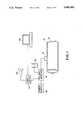
- FIG. 1is a schematic representation of the apparatus of the present invention
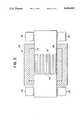
- FIG. 2is a perspective view of a portion of the preferred embodiment of the present invention.
- FIG. 3is a bottom view of the carriage (30) depicting the EMATs
- FIG. 4is a gate circuit schematic of the logic circuit discriminating means according to the present invention.
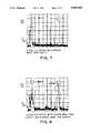
- FIGS. 5-8are photographs of an oscilloscope screen showing examples of signals in accordance with the present invention.
- FIG. 1there is illustrated a schematic block diagram of the present invention in place on a workpiece (10).
- a pipe or tube (10)is manufactured from flat stock by being bent into a cylindrical shape and welded to form a longitudinal seam or a weld line (12) along the pipe (10) in a manner well known in this art.
- the pipe (10)is then positioned for final examination in a holding mechanism (not shown).
- a transducer (14) operating in a pulse-echo modegenerates both ultrasonic surface and shear waves for inspecting the area around the weld line (12).
- a pulser/receiver (16) operated by a power supply (18)receives the propagated ultrasonic waves and displays them on an oscilloscope (20). The displayed amplitudes of the ultrasonic waves provide an indication of flaws and their corresponding depths when calibration standards are employed.
- a logic circuit discriminating means (22)also receives the ultrasonic waves to identify flaw depths of 5% and 10% of the tube wall thickness of the electric resistance weld.
- the logic circuit discriminating means (22)provides an alarm (24) which may be audio, visual or both whenever an inner diameter or outer diameter flaw has a throughwall depth of about 10% or greater.
- the logic circuit (22)does not activate the alarm (24) for a flaw with a depth of 5% or less.
- the logic circuit discriminating means (22)may be a stand-alone unit or may be integrated as a circuit board into the pulser-receiver (16).
- a computer or microprocessor (26)may be provided in communication with the logic circuit (22) for further calculations or recording the data with a printer (not shown).
- transducer (14)consists of a pulsed magnet (28) held in a carriage (30) as best seen in FIGS. 2 and 3.
- EMATselectromagnetic acoustic transducers
- the two meander grids of EMATs (32, 34)are superimposed over each other.
- One of the EMATs (34)generates surface waves.
- the other EMAT (32)generates SV shear waves at an angle of incidence of about 30° in the preferred embodiment.
- Carriage (30)is fabricated of suitable material such as aluminum and has wheels (36) which facilitates the inspection process. It is to be understood that the present invention is operable with other inspection systems as long as there is provided at least two EMATs (32, 34) with one generating surface waves and the other shear waves.
- the operating principle of the present inventionis based upon the fact that there is a difference in ultrasonic amplitude reflected from a flaw that is related to the flaw throughwall depth and also whether the flaw is positioned at the outer diameter or inner diameter as well as other geometrical factors.
- the present inventionprovides a method and apparatus for throughwall depth discrimination.
- the attached circuittakes the two incoming signals, one a shear wave signal (38) and the other a surface wave signal (40), and generates indications for ID or OD flaws of greater than a preset depth.
- Integrated circuits IC1, IC2, and IC3are analog comparators, preferably LM339 comparators, configured to generate the required logic signals.
- the variable resistors R1, R2, and R3, which are preferably 10K resistors,are used to set the thresholds for the alarm levels.
- the combination of IC1 and R1set the shear wave alarm level, while IC2 and R2 set the surface wave alarm level.
- the combination of IC3 and R3set the noise threshold for the surface wave signal that is necessary to perform the flaw discrimination.
- An OD (42) flawwill be indicated when both the shear wave and surface wave signals are above their respective alarm levels, with this signal being generated by the AND gate, IC4.
- the shear wave signalis above its alarm threshold and the surface wave signal is below the noise threshold, it indicates the presence of an ID flaw, generated by the output of AND gate IC5 to ID flaw alarm (44).
- the transducer (14), pulser/receiver (16) and oscilloscope (20)are calibrated for the shear wave channel and the surface wave channel.
- the gate for the shear wave signal (38)is set to trigger an alarm for an inner diameter (ID) and outer diameter (OD) notch depth that is about 10% or greater of the tube wall thickness. Consequently, this provides an alarm for a 5% outer diameter (OD) notch in most cases but not for a 5% ID notch due to its inherent sensitivity characteristics.
- the fact that the 5% OD notch alarms in most (but not all) casesis due to the fact that the amplitude response from an OD notch is usually greater than the amplitude response from a similar ID notch when 30° shear waves are used in cylindrical geometry.
- the gate for the surface wave signal (40)is set to trigger an alarm for an OD notch depth of about 10% or greater of the tube wall thickness. This does not trigger an alarm for 5% OD notch.
- FIGS. 5-8are photographs of these signals on an oscilloscope. In all of the photographs, each division on the oscilloscope represents 0.2 V.
- the gate threshold for both the surface and shear wavesis set at 1.4 V.
- the adjustable noise thresholdis set at 0.26 V.
- FIG. 5shows a 5% OD notch with approximate shear wave trip (left) with no surface wave trip (right).
- FIG. 6shows a 5% ID notch with no shear wave trip (left).
- FIG. 7shows a 10% ID notch with shear wave trip (left).
- FIG. 8shows a 10% OD notch with a shear wave trip (left) and surface wave trip (right).
- Example Iboth gates for the shear wave signal (38) and the surface wave signal (40) trip to indicate the presence of a flaw depth of 10% or greater (as shown in FIG. 8) and activate the OD flaw alarm (42) by means of the "AND" gate (IC4). This results in OD alarm (42) from the logic circuit (22) activating the alarm (24) to alert the inspector.
- Example IIwhen the gate for the shear wave signal (38) trips but the gate for the surface wave signal (40) does not trip, then there may be two cases: (a) 10% ID flaw, or (b) 5% OD flaw.
- logic circuit (22)provides an adjustable threshold detector via the combination of analog comparator (IC3) and variable resistor (R3) derived from the surface wave signal (40) in addition to the usual surface wave channel gate (IC2, R2) for distinguishing between cases (a) and (b).
- the adjustable thresholdis set just above the noise level. In this manner, the adjustable threshold detector (IC3, R3) indicates the presence or absence of a signal that is below the threshold of the surface wave channel.
- the shear wave channel signal (38)trips the gate (IC1, R1) and there is no signal in the adjustable gate inverter (IC3, R3) then there is a signal sent due to its logic function to the "AND” gate (IC5).
- a signalis also transmitted to the "AND” gate (IC5) from the shear wave channel gate (IC1, R1) which triggers the ID flaw alarm (44) thereby activating the alarm (24) to indicate (a) 10% ID flaw.
- the operating principle of the present inventionis based upon the fact that there is a difference in ultrasonic amplitude reflected from a flaw that is related to the flaw through wall depth and also whether the flaw is positioned at the outer diameter or inner diameter as well as other geometrical factors.
- the present inventionprovides for inspection speeds that are compatible with present and anticipated production speed. It has been tested at rates of 50 ft./min. and 100 ft./min. Conventional ultrasonic techniques are limited in scanning rate by problems associated with ultrasonic couplant.
Landscapes
- Physics & Mathematics (AREA)
- Health & Medical Sciences (AREA)
- Life Sciences & Earth Sciences (AREA)
- Chemical & Material Sciences (AREA)
- Analytical Chemistry (AREA)
- Biochemistry (AREA)
- General Health & Medical Sciences (AREA)
- General Physics & Mathematics (AREA)
- Immunology (AREA)
- Pathology (AREA)
- Acoustics & Sound (AREA)
- Electromagnetism (AREA)
- Engineering & Computer Science (AREA)
- Signal Processing (AREA)
- Investigating Or Analyzing Materials By The Use Of Ultrasonic Waves (AREA)
Abstract
Description
Claims (9)
Priority Applications (3)
| Application Number | Priority Date | Filing Date | Title |
|---|---|---|---|
| US07/603,334US5085082A (en) | 1990-10-24 | 1990-10-24 | Apparatus and method of discriminating flaw depths in the inspection of tubular products |
| CA002052389ACA2052389A1 (en) | 1990-10-24 | 1991-09-27 | Apparatus and method of discriminating flaw depths in the inspection of tubular products |
| JP3296573AJPH04265853A (en) | 1990-10-24 | 1991-10-17 | Method and apparatus for identifying flaw depth in checking of tubular product |
Applications Claiming Priority (1)
| Application Number | Priority Date | Filing Date | Title |
|---|---|---|---|
| US07/603,334US5085082A (en) | 1990-10-24 | 1990-10-24 | Apparatus and method of discriminating flaw depths in the inspection of tubular products |
Publications (1)
| Publication Number | Publication Date |
|---|---|
| US5085082Atrue US5085082A (en) | 1992-02-04 |
Family
ID=24414986
Family Applications (1)
| Application Number | Title | Priority Date | Filing Date |
|---|---|---|---|
| US07/603,334Expired - LifetimeUS5085082A (en) | 1990-10-24 | 1990-10-24 | Apparatus and method of discriminating flaw depths in the inspection of tubular products |
Country Status (3)
| Country | Link |
|---|---|
| US (1) | US5085082A (en) |
| JP (1) | JPH04265853A (en) |
| CA (1) | CA2052389A1 (en) |
Cited By (53)
| Publication number | Priority date | Publication date | Assignee | Title |
|---|---|---|---|---|
| US5359898A (en)* | 1991-06-04 | 1994-11-01 | The Babcock & Wilcox Company | Hydrogen damage confirmation with EMATs |
| US5383365A (en)* | 1992-09-17 | 1995-01-24 | The Babcock & Wilcox Company | Crack orientation determination and detection using horizontally polarized shear waves |
| US5439157A (en)* | 1994-07-18 | 1995-08-08 | The Babcock & Wilcox Company | Automated butt weld inspection system |
| US5474225A (en)* | 1994-07-18 | 1995-12-12 | The Babcock & Wilcox Company | Automated method for butt weld inspection and defect diagnosis |
| US5648611A (en)* | 1993-12-22 | 1997-07-15 | The Timken Company | Process for measuring the case depth of case-carburized steel |
| US5652389A (en)* | 1996-05-22 | 1997-07-29 | The United States Of America As Represented By The Secretary Of Commerce | Non-contact method and apparatus for inspection of inertia welds |
| US5750900A (en)* | 1996-09-09 | 1998-05-12 | Sonicforce, L.L.C. | Acoustic strain gauge and assembly and method for measuring strain |
| US5760307A (en)* | 1994-03-18 | 1998-06-02 | Latimer; Paul J. | EMAT probe and technique for weld inspection |
| US5763786A (en)* | 1996-09-18 | 1998-06-09 | The Babcock & Wilcox Company | Automated mill roll inspection system |
| US5808201A (en)* | 1996-09-09 | 1998-09-15 | Sonicforce, L.L.C. | Acoustic strain gauge |
| US5866820A (en)* | 1996-09-20 | 1999-02-02 | Camplin; Kenneth R. | Coil volumetric and surface defect detection system |
| US5907100A (en)* | 1997-06-30 | 1999-05-25 | Gas Research Institute | Method and system for detecting and displaying defects in piping |
| US6142359A (en)* | 1997-02-17 | 2000-11-07 | T J Corbishley (Developments) Ltd. | Method of connecting pipe-in-pipe structures |
| US6158285A (en)* | 1997-08-26 | 2000-12-12 | Mcdermott Technology, Inc. | EMAT inspection of welds in thin steel plates of dissimilar thicknesses |
| US6164137A (en)* | 1999-02-03 | 2000-12-26 | Mcdermott Technology, Inc. | Electromagnetic acoustic transducer (EMAT) inspection of tubes for surface defects |
| US6192760B1 (en) | 1999-08-19 | 2001-02-27 | Mcdermott Technology, Inc. | EMAT transmit/receive switch |
| US6282964B1 (en)* | 1999-09-17 | 2001-09-04 | The Babcock & Wilcox Co | Electromagnetic acoustic transducer (EMAT) inspection of cracks in boiler tubes |
| US6344739B1 (en) | 1999-02-12 | 2002-02-05 | R/D Tech Inc. | Eddy current probe with multi-use coils and compact configuration |
| US6443011B1 (en)* | 1997-11-19 | 2002-09-03 | Inoex Gmbh | Device for detecting errors and/or measuring wall thickness in continuous strips or tubes made of plastic using ultrasonic signals |
| US6477473B2 (en)* | 1998-07-30 | 2002-11-05 | Don E. Bray | Ultrasonic stress measurement using the critically refracted longitudinal (LCR) ultrasonic technique |
| WO2004007138A1 (en)* | 2002-07-17 | 2004-01-22 | Shell Internationale Research Maatschappij B.V. | Electromagnetic acoustic transducer (emat) weld inspection |
| US6681632B2 (en)* | 2000-03-23 | 2004-01-27 | Snecma Moteurs | Method for evaluating the resilience of a welded assembly and corresponding analysis apparatus measuring the speeds of ultrasonic surface waves |
| US20040020297A1 (en)* | 2000-09-27 | 2004-02-05 | Digital Wave Corporation | Device and method designed for ultrasonically inspecting cylinders for longitudinal and circumferential defects and to measure wall thickness |
| US20040237653A1 (en)* | 2001-07-05 | 2004-12-02 | Alfred Graff | Device for ultrasonic weld seam testing of longitudinally welded pipes for longitudinal and transversal errors |
| US20050050726A1 (en)* | 2002-07-17 | 2005-03-10 | Anderson Mark Wilson | Joining expandable tubulars |
| US20050210953A1 (en)* | 2002-05-17 | 2005-09-29 | Paul Buschke | Method for determining temporal and amplitude threshold values of gates during ultrasound testing of spot welding joints |
| FR2879292A1 (en)* | 2004-12-09 | 2006-06-16 | Framatome Anp Sas | Metallic or composite part, e.g. welding seam, testing for e.g. nuclear power plant, involves displaying signal on spectacles in superposition with zone`s direct view and adjusting parameters by voice command upon finding zone defect |
| EP0829714A4 (en)* | 1996-03-28 | 2007-06-27 | Mitsubishi Electric Corp | ULTRASONIC FAULT DETECTOR AND ULTRASONIC FAULT DETECTION METHOD |
| US20070158390A1 (en)* | 2003-07-17 | 2007-07-12 | Anderson Mark W | Forge welding tubulars |
| US7282663B2 (en) | 2002-07-29 | 2007-10-16 | Shell Oil Company | Forge welding process |
| WO2009024111A1 (en)* | 2007-08-17 | 2009-02-26 | V & M Deutschland Gmbh | Process for the destruction-free testing of pipes |
| US20090140026A1 (en)* | 2006-04-11 | 2009-06-04 | Kawasaki Jukogyo Kabushiki Kaisha | Method and Apparatus for Inspecting Joined Object Formed by Friction Stir Joining |
| US20100117635A1 (en)* | 2008-11-12 | 2010-05-13 | Hoyt Philip M | Spiral magnetic field apparatus and method for pipeline inspection |
| EP2159575A3 (en)* | 2005-07-07 | 2010-07-28 | Kabushiki Kaisha Toshiba | Laser-based apparatus for ultrasonic flaw detection |
| US20100288049A1 (en)* | 2008-08-08 | 2010-11-18 | Hoyt Philip M | Pseudorandom binary sequence apparatus and method for in-line inspection tool |
| US20110239770A1 (en)* | 2008-11-19 | 2011-10-06 | Sumitomo Metal Industries, Ltd | Method and apparatus for ultrasonic testing of weld zones |
| US20110296922A1 (en)* | 2010-06-07 | 2011-12-08 | Syed Mohamed Ali | Emat for inspecting thick-section welds and weld overlays during the welding process |
| CN102866205A (en)* | 2012-09-12 | 2013-01-09 | 田志恒 | Electromagnetic ultrasonic transducer and online flaw detection system with same |
| CN102980942A (en)* | 2012-11-20 | 2013-03-20 | 中国石油天然气集团公司 | Metal pipeline detection device and method |
| US9291520B2 (en) | 2011-08-12 | 2016-03-22 | Mueller International, Llc | Fire hydrant leak detector |
| US9528903B2 (en) | 2014-10-01 | 2016-12-27 | Mueller International, Llc | Piezoelectric vibration sensor for fluid leak detection |
| US9849322B2 (en) | 2010-06-16 | 2017-12-26 | Mueller International, Llc | Infrastructure monitoring devices, systems, and methods |
| CN107894463A (en)* | 2017-12-28 | 2018-04-10 | 中国石油天然气集团公司管材研究所 | The reference block of ERW steel pipe seam electromagnetic acoustic automatic detections and design method |
| US9939344B2 (en) | 2012-10-26 | 2018-04-10 | Mueller International, Llc | Detecting leaks in a fluid distribution system |
| CN108982670A (en)* | 2018-08-23 | 2018-12-11 | 湖州市特种设备检测研究院 | A kind of electromagnetic ultrasonic probe of water pipe non-destructive testing |
| CN109030630A (en)* | 2018-07-15 | 2018-12-18 | 东北石油大学 | A kind of non-contact automatic tester of electromagnetic acoustic for storage tank bottom plate weld seam |
| US10283857B2 (en) | 2016-02-12 | 2019-05-07 | Mueller International, Llc | Nozzle cap multi-band antenna assembly |
| US10305178B2 (en) | 2016-02-12 | 2019-05-28 | Mueller International, Llc | Nozzle cap multi-band antenna assembly |
| CN109844517A (en)* | 2016-10-19 | 2019-06-04 | 塞佩姆股份公司 | Method for automatically checking a weld bead deposited in a groove formed between two metal sheets to be assembled |
| US10859462B2 (en) | 2018-09-04 | 2020-12-08 | Mueller International, Llc | Hydrant cap leak detector with oriented sensor |
| US11342656B2 (en) | 2018-12-28 | 2022-05-24 | Mueller International, Llc | Nozzle cap encapsulated antenna system |
| US11473993B2 (en) | 2019-05-31 | 2022-10-18 | Mueller International, Llc | Hydrant nozzle cap |
| US11542690B2 (en) | 2020-05-14 | 2023-01-03 | Mueller International, Llc | Hydrant nozzle cap adapter |
Families Citing this family (2)
| Publication number | Priority date | Publication date | Assignee | Title |
|---|---|---|---|---|
| JP2010025555A (en)* | 2008-07-15 | 2010-02-04 | Daikure Co Ltd | Method and device for measuring wall thickness of high temperature vessel |
| CN111121678B (en)* | 2018-10-31 | 2021-06-01 | 中国石油天然气股份有限公司 | Pipeline wall thickness detection method and device |
Citations (6)
| Publication number | Priority date | Publication date | Assignee | Title |
|---|---|---|---|---|
| US3868847A (en)* | 1972-12-04 | 1975-03-04 | Walter A Gunkel | System and apparatus for inspecting elongated welds |
| US4351190A (en)* | 1979-12-17 | 1982-09-28 | Wilfried Rehme | Ultrasonic non-destructive testing device for welding beads |
| JPS61122562A (en)* | 1984-11-20 | 1986-06-10 | Mitsubishi Heavy Ind Ltd | Measuring method of depth of cracking |
| US4660419A (en)* | 1983-10-03 | 1987-04-28 | Trw Inc. | Reference standard for calibration of ultrasonic arrays |
| US4727321A (en)* | 1985-05-03 | 1988-02-23 | Nukem Gmbh | Method and device for magnetic and ultrasonic testing of ferro-magnetic objects |
| US4926692A (en)* | 1986-04-18 | 1990-05-22 | Polska Akademia Nauk Instytut Podstrowowych Problemow | Method of measurement of residual stresses in the material of the object under test |
Family Cites Families (5)
| Publication number | Priority date | Publication date | Assignee | Title |
|---|---|---|---|---|
| JPS5896247A (en)* | 1981-12-03 | 1983-06-08 | Hitachi Ltd | Weld detection device |
| JPS59135363A (en)* | 1983-01-24 | 1984-08-03 | Sumitomo Metal Ind Ltd | Ultrasonic flaw detection of small diameter thin walled pipe |
| JPS62162958A (en)* | 1986-01-13 | 1987-07-18 | Mitsubishi Electric Corp | Ultrasonic flaw detecting method |
| JPH01248052A (en)* | 1988-03-29 | 1989-10-03 | Sumitomo Metal Ind Ltd | Ultrasonic flaw detection method and equipment |
| JPH02159555A (en)* | 1988-12-13 | 1990-06-19 | Sumitomo Metal Ind Ltd | ERW steel pipe ultrasonic flaw detection equipment |
- 1990
- 1990-10-24USUS07/603,334patent/US5085082A/ennot_activeExpired - Lifetime
- 1991
- 1991-09-27CACA002052389Apatent/CA2052389A1/ennot_activeAbandoned
- 1991-10-17JPJP3296573Apatent/JPH04265853A/enactivePending
Patent Citations (6)
| Publication number | Priority date | Publication date | Assignee | Title |
|---|---|---|---|---|
| US3868847A (en)* | 1972-12-04 | 1975-03-04 | Walter A Gunkel | System and apparatus for inspecting elongated welds |
| US4351190A (en)* | 1979-12-17 | 1982-09-28 | Wilfried Rehme | Ultrasonic non-destructive testing device for welding beads |
| US4660419A (en)* | 1983-10-03 | 1987-04-28 | Trw Inc. | Reference standard for calibration of ultrasonic arrays |
| JPS61122562A (en)* | 1984-11-20 | 1986-06-10 | Mitsubishi Heavy Ind Ltd | Measuring method of depth of cracking |
| US4727321A (en)* | 1985-05-03 | 1988-02-23 | Nukem Gmbh | Method and device for magnetic and ultrasonic testing of ferro-magnetic objects |
| US4926692A (en)* | 1986-04-18 | 1990-05-22 | Polska Akademia Nauk Instytut Podstrowowych Problemow | Method of measurement of residual stresses in the material of the object under test |
Cited By (100)
| Publication number | Priority date | Publication date | Assignee | Title |
|---|---|---|---|---|
| US5359898A (en)* | 1991-06-04 | 1994-11-01 | The Babcock & Wilcox Company | Hydrogen damage confirmation with EMATs |
| US5383365A (en)* | 1992-09-17 | 1995-01-24 | The Babcock & Wilcox Company | Crack orientation determination and detection using horizontally polarized shear waves |
| US5648611A (en)* | 1993-12-22 | 1997-07-15 | The Timken Company | Process for measuring the case depth of case-carburized steel |
| US5760307A (en)* | 1994-03-18 | 1998-06-02 | Latimer; Paul J. | EMAT probe and technique for weld inspection |
| WO1996002832A1 (en)* | 1994-07-18 | 1996-02-01 | The Babcock & Wilcox Company | Automated butt weld inspection system |
| WO1996002349A1 (en)* | 1994-07-18 | 1996-02-01 | The Babcock & Wilcox Company | Automated method for butt weld inspection and defect diagnosis |
| US5474225A (en)* | 1994-07-18 | 1995-12-12 | The Babcock & Wilcox Company | Automated method for butt weld inspection and defect diagnosis |
| US5439157A (en)* | 1994-07-18 | 1995-08-08 | The Babcock & Wilcox Company | Automated butt weld inspection system |
| EP0829714A4 (en)* | 1996-03-28 | 2007-06-27 | Mitsubishi Electric Corp | ULTRASONIC FAULT DETECTOR AND ULTRASONIC FAULT DETECTION METHOD |
| US5652389A (en)* | 1996-05-22 | 1997-07-29 | The United States Of America As Represented By The Secretary Of Commerce | Non-contact method and apparatus for inspection of inertia welds |
| US5750900A (en)* | 1996-09-09 | 1998-05-12 | Sonicforce, L.L.C. | Acoustic strain gauge and assembly and method for measuring strain |
| US5808201A (en)* | 1996-09-09 | 1998-09-15 | Sonicforce, L.L.C. | Acoustic strain gauge |
| US5763786A (en)* | 1996-09-18 | 1998-06-09 | The Babcock & Wilcox Company | Automated mill roll inspection system |
| US5866820A (en)* | 1996-09-20 | 1999-02-02 | Camplin; Kenneth R. | Coil volumetric and surface defect detection system |
| US6142359A (en)* | 1997-02-17 | 2000-11-07 | T J Corbishley (Developments) Ltd. | Method of connecting pipe-in-pipe structures |
| US5907100A (en)* | 1997-06-30 | 1999-05-25 | Gas Research Institute | Method and system for detecting and displaying defects in piping |
| US6158285A (en)* | 1997-08-26 | 2000-12-12 | Mcdermott Technology, Inc. | EMAT inspection of welds in thin steel plates of dissimilar thicknesses |
| US6443011B1 (en)* | 1997-11-19 | 2002-09-03 | Inoex Gmbh | Device for detecting errors and/or measuring wall thickness in continuous strips or tubes made of plastic using ultrasonic signals |
| US6477473B2 (en)* | 1998-07-30 | 2002-11-05 | Don E. Bray | Ultrasonic stress measurement using the critically refracted longitudinal (LCR) ultrasonic technique |
| US6164137A (en)* | 1999-02-03 | 2000-12-26 | Mcdermott Technology, Inc. | Electromagnetic acoustic transducer (EMAT) inspection of tubes for surface defects |
| US6344739B1 (en) | 1999-02-12 | 2002-02-05 | R/D Tech Inc. | Eddy current probe with multi-use coils and compact configuration |
| US6192760B1 (en) | 1999-08-19 | 2001-02-27 | Mcdermott Technology, Inc. | EMAT transmit/receive switch |
| US6282964B1 (en)* | 1999-09-17 | 2001-09-04 | The Babcock & Wilcox Co | Electromagnetic acoustic transducer (EMAT) inspection of cracks in boiler tubes |
| US6681632B2 (en)* | 2000-03-23 | 2004-01-27 | Snecma Moteurs | Method for evaluating the resilience of a welded assembly and corresponding analysis apparatus measuring the speeds of ultrasonic surface waves |
| US20050061077A1 (en)* | 2000-09-27 | 2005-03-24 | Digital Wave Corporation | Device and method designed for ultrasonically inspecting cylinders for longitudinal and circumferential defects and to measure wall thickness |
| US6851319B2 (en) | 2000-09-27 | 2005-02-08 | Digital Wave Corporation | Device and method designed for ultrasonically inspecting cylinders for longitudinal and circumferential defects and to measure wall thickness |
| US20040020297A1 (en)* | 2000-09-27 | 2004-02-05 | Digital Wave Corporation | Device and method designed for ultrasonically inspecting cylinders for longitudinal and circumferential defects and to measure wall thickness |
| US6931931B2 (en)* | 2001-07-05 | 2005-08-23 | Mannesmannröhren-Werke Ag | Device for ultrasonic weld seam testing of longitudinally welded pipes for longitudinal and transversal errors |
| US20040237653A1 (en)* | 2001-07-05 | 2004-12-02 | Alfred Graff | Device for ultrasonic weld seam testing of longitudinally welded pipes for longitudinal and transversal errors |
| US7210329B2 (en)* | 2002-05-17 | 2007-05-01 | Agfa Ndt Gmbh | Method for determining temporal and amplitude threshold values of gates during ultrasound testing of spot welding joints |
| US20050210953A1 (en)* | 2002-05-17 | 2005-09-29 | Paul Buschke | Method for determining temporal and amplitude threshold values of gates during ultrasound testing of spot welding joints |
| US6896171B2 (en) | 2002-07-17 | 2005-05-24 | Shell Oil Company | EMAT weld inspection |
| CN100385236C (en)* | 2002-07-17 | 2008-04-30 | 国际壳牌研究有限公司 | Electromagnetic Acoustic Transducer (EMAT) Weld Inspection |
| WO2004007138A1 (en)* | 2002-07-17 | 2004-01-22 | Shell Internationale Research Maatschappij B.V. | Electromagnetic acoustic transducer (emat) weld inspection |
| US7181821B2 (en) | 2002-07-17 | 2007-02-27 | Shell Oil Company | Joining expandable tubulars |
| US20040134970A1 (en)* | 2002-07-17 | 2004-07-15 | Den Boer Johannis Josephus | EMAT weld inspection |
| US20050050726A1 (en)* | 2002-07-17 | 2005-03-10 | Anderson Mark Wilson | Joining expandable tubulars |
| US7282663B2 (en) | 2002-07-29 | 2007-10-16 | Shell Oil Company | Forge welding process |
| US7774917B2 (en) | 2003-07-17 | 2010-08-17 | Tubefuse Applications B.V. | Forge welding tubulars |
| US20070158390A1 (en)* | 2003-07-17 | 2007-07-12 | Anderson Mark W | Forge welding tubulars |
| FR2879292A1 (en)* | 2004-12-09 | 2006-06-16 | Framatome Anp Sas | Metallic or composite part, e.g. welding seam, testing for e.g. nuclear power plant, involves displaying signal on spectacles in superposition with zone`s direct view and adjusting parameters by voice command upon finding zone defect |
| US8094297B2 (en) | 2005-07-07 | 2012-01-10 | Kabushiki Kaisha Toshiba | Laser-based maintenance apparatus for inspecting flaws |
| US8248595B2 (en) | 2005-07-07 | 2012-08-21 | Kabushiki Kaisha Toshiba | Laser-based maintenance apparatus for inspecting flaws based on a generated surface wave |
| EP2159575A3 (en)* | 2005-07-07 | 2010-07-28 | Kabushiki Kaisha Toshiba | Laser-based apparatus for ultrasonic flaw detection |
| US20100199768A1 (en)* | 2005-07-07 | 2010-08-12 | Kabushiki Kaisha Toshiba | Laser-based maintenance apparatus |
| US20090140026A1 (en)* | 2006-04-11 | 2009-06-04 | Kawasaki Jukogyo Kabushiki Kaisha | Method and Apparatus for Inspecting Joined Object Formed by Friction Stir Joining |
| US7861910B2 (en)* | 2006-04-11 | 2011-01-04 | Kawasaki Jukogyo Kabushiki Kaisha | Method and apparatus for inspecting joined object formed by friction stir joining |
| US8590766B2 (en) | 2006-04-11 | 2013-11-26 | Kawasaki Jukogyo Kabushiki Kaisha | Method and apparatus for inspecting joined object formed by friction stir joining |
| WO2009024111A1 (en)* | 2007-08-17 | 2009-02-26 | V & M Deutschland Gmbh | Process for the destruction-free testing of pipes |
| US8490492B2 (en) | 2007-08-17 | 2013-07-23 | V & M Deutschland Gmbh | Method for nondestructive testing of pipes |
| US20100288049A1 (en)* | 2008-08-08 | 2010-11-18 | Hoyt Philip M | Pseudorandom binary sequence apparatus and method for in-line inspection tool |
| US8631705B2 (en) | 2008-08-08 | 2014-01-21 | Pure Technologies Ltd. | Pseudorandom binary sequence apparatus and method for in-line inspection tool |
| US8322219B2 (en) | 2008-08-08 | 2012-12-04 | Pure Technologies Ltd. | Pseudorandom binary sequence apparatus and method for in-line inspection tool |
| US7923994B2 (en) | 2008-11-12 | 2011-04-12 | Hoyt Philip M | Spiral magnetic field apparatus and method for pipeline inspection |
| US20110181275A1 (en)* | 2008-11-12 | 2011-07-28 | Hoyt Philip M | Spiral magnetic field apparatus and method for pipeline inspection |
| US20100117635A1 (en)* | 2008-11-12 | 2010-05-13 | Hoyt Philip M | Spiral magnetic field apparatus and method for pipeline inspection |
| US8089273B2 (en) | 2008-11-12 | 2012-01-03 | Hoyt Philip M | Spiral magnetic field apparatus and method for pipeline inspection |
| US20110239770A1 (en)* | 2008-11-19 | 2011-10-06 | Sumitomo Metal Industries, Ltd | Method and apparatus for ultrasonic testing of weld zones |
| US8387462B2 (en)* | 2008-11-19 | 2013-03-05 | Sumitomo Metal Industries, Ltd. | Method and apparatus for ultrasonic testing of weld zones |
| US20110296922A1 (en)* | 2010-06-07 | 2011-12-08 | Syed Mohamed Ali | Emat for inspecting thick-section welds and weld overlays during the welding process |
| US9849322B2 (en) | 2010-06-16 | 2017-12-26 | Mueller International, Llc | Infrastructure monitoring devices, systems, and methods |
| US11590376B2 (en) | 2010-06-16 | 2023-02-28 | Mueller International, Llc | Infrastructure monitoring devices, systems, and methods |
| US10881888B2 (en) | 2010-06-16 | 2021-01-05 | Mueller International, Llc | Infrastructure monitoring devices, systems, and methods |
| US10857403B2 (en) | 2010-06-16 | 2020-12-08 | Mueller International, Llc | Infrastructure monitoring devices, systems, and methods |
| US9861848B2 (en) | 2010-06-16 | 2018-01-09 | Mueller International, Llc | Infrastructure monitoring devices, systems, and methods |
| US10386257B2 (en) | 2011-08-12 | 2019-08-20 | Mueller International, Llc | Enclosure for leak detector |
| US9772250B2 (en) | 2011-08-12 | 2017-09-26 | Mueller International, Llc | Leak detector and sensor |
| US9291520B2 (en) | 2011-08-12 | 2016-03-22 | Mueller International, Llc | Fire hydrant leak detector |
| US11680865B2 (en) | 2011-08-12 | 2023-06-20 | Mueller International, Llc | Leak detection in water distribution systems using acoustic signals |
| US11630021B2 (en) | 2011-08-12 | 2023-04-18 | Mueller International, Llc | Enclosure for leak detector |
| US10175135B2 (en) | 2011-08-12 | 2019-01-08 | Mueller International, Llc | Leak detector |
| US9593999B2 (en) | 2011-08-12 | 2017-03-14 | Mueller International, Llc | Enclosure for leak detector |
| CN102866205A (en)* | 2012-09-12 | 2013-01-09 | 田志恒 | Electromagnetic ultrasonic transducer and online flaw detection system with same |
| CN102866205B (en)* | 2012-09-12 | 2015-07-15 | 田志恒 | Electromagnetic ultrasonic transducer and online flaw detection system with same |
| US9939344B2 (en) | 2012-10-26 | 2018-04-10 | Mueller International, Llc | Detecting leaks in a fluid distribution system |
| CN102980942A (en)* | 2012-11-20 | 2013-03-20 | 中国石油天然气集团公司 | Metal pipeline detection device and method |
| CN102980942B (en)* | 2012-11-20 | 2015-04-08 | 中国石油天然气集团公司 | Metal pipeline detection method |
| US9528903B2 (en) | 2014-10-01 | 2016-12-27 | Mueller International, Llc | Piezoelectric vibration sensor for fluid leak detection |
| US11336004B2 (en) | 2016-02-12 | 2022-05-17 | Mueller International, Llc | Nozzle cap multi-band antenna assembly |
| US10305178B2 (en) | 2016-02-12 | 2019-05-28 | Mueller International, Llc | Nozzle cap multi-band antenna assembly |
| US10283857B2 (en) | 2016-02-12 | 2019-05-07 | Mueller International, Llc | Nozzle cap multi-band antenna assembly |
| US12212053B2 (en) | 2016-02-12 | 2025-01-28 | Mueller International, Llc | Nozzle cap multi-band antenna assembly |
| US11469494B2 (en) | 2016-02-12 | 2022-10-11 | Mueller International, Llc | Nozzle cap multi-band antenna assembly |
| US11837782B2 (en) | 2016-02-12 | 2023-12-05 | Mueller International, Llc | Nozzle cap assembly |
| US11527821B2 (en) | 2016-02-12 | 2022-12-13 | Mueller International, Llc | Nozzle cap assembly |
| US11652284B2 (en) | 2016-02-12 | 2023-05-16 | Mueller International, Llc | Nozzle cap assembly |
| CN109844517A (en)* | 2016-10-19 | 2019-06-04 | 塞佩姆股份公司 | Method for automatically checking a weld bead deposited in a groove formed between two metal sheets to be assembled |
| CN107894463B (en)* | 2017-12-28 | 2023-12-08 | 中国石油天然气集团有限公司 | Reference block for electromagnetic ultrasonic automatic detection of ERW steel pipe weld joint and design method |
| CN107894463A (en)* | 2017-12-28 | 2018-04-10 | 中国石油天然气集团公司管材研究所 | The reference block of ERW steel pipe seam electromagnetic acoustic automatic detections and design method |
| CN109030630A (en)* | 2018-07-15 | 2018-12-18 | 东北石油大学 | A kind of non-contact automatic tester of electromagnetic acoustic for storage tank bottom plate weld seam |
| CN108982670A (en)* | 2018-08-23 | 2018-12-11 | 湖州市特种设备检测研究院 | A kind of electromagnetic ultrasonic probe of water pipe non-destructive testing |
| US11422054B2 (en) | 2018-09-04 | 2022-08-23 | Mueller International, Llc | Hydrant cap leak detector with oriented sensor |
| US11692901B2 (en) | 2018-09-04 | 2023-07-04 | Mueller International, Llc | Hydrant cap leak detector with oriented sensor |
| US10859462B2 (en) | 2018-09-04 | 2020-12-08 | Mueller International, Llc | Hydrant cap leak detector with oriented sensor |
| US11342656B2 (en) | 2018-12-28 | 2022-05-24 | Mueller International, Llc | Nozzle cap encapsulated antenna system |
| US11624674B2 (en) | 2019-05-31 | 2023-04-11 | Mueller International, Llc | Hydrant nozzle cap with antenna |
| US11473993B2 (en) | 2019-05-31 | 2022-10-18 | Mueller International, Llc | Hydrant nozzle cap |
| US12078572B2 (en) | 2019-05-31 | 2024-09-03 | Mueller International, Llc | Hydrant nozzle cap |
| US11542690B2 (en) | 2020-05-14 | 2023-01-03 | Mueller International, Llc | Hydrant nozzle cap adapter |
| US12084844B2 (en) | 2020-05-14 | 2024-09-10 | Mueller International, Llc | Hydrant nozzle cap adapter |
Also Published As
| Publication number | Publication date |
|---|---|
| JPH04265853A (en) | 1992-09-22 |
| CA2052389A1 (en) | 1992-04-25 |
Similar Documents
| Publication | Publication Date | Title |
|---|---|---|
| US5085082A (en) | Apparatus and method of discriminating flaw depths in the inspection of tubular products | |
| US4619143A (en) | Apparatus and method for the non-destructive inspection of solid bodies | |
| US4658649A (en) | Ultrasonic method and device for detecting and measuring defects in metal media | |
| US7789286B2 (en) | Method and apparatus for assessing the quality of spot welds | |
| US5661241A (en) | Ultrasonic technique for measuring the thickness of cladding on the inside surface of vessels from the outside diameter surface | |
| US4627289A (en) | Method for the ultrasonic flaw detection of an electric welded pipe | |
| CA1221162A (en) | Apparatus and method for the non-destructive inspection of solid bodies | |
| KR101921685B1 (en) | Apparatus for inspecting defect and mehtod for inspecting defect using the same | |
| JPS6128863A (en) | Nondestructive inspection method of processing member by ultrasonic wave and device thereof | |
| US4265119A (en) | Ultrasonic method of inspecting spot welds | |
| JPH0350221B2 (en) | ||
| CA2012374C (en) | Ultrasonic crack sizing method | |
| JPH06105240B2 (en) | Air bubble detector | |
| JP2002277447A (en) | Ultrasonic flaw detection method and apparatus | |
| GB2124379A (en) | Improvements in or relating to ultrasonic testing | |
| JPH09304363A (en) | Ultrasonic flaw detection method for austenitic stainless castings | |
| CA1194979A (en) | Method for distinguishing between interfering signals and signals indicating defects of workpieces during ultrasonic testing | |
| US6158285A (en) | EMAT inspection of welds in thin steel plates of dissimilar thicknesses | |
| JP3478178B2 (en) | Ultrasonic flaw detection method and apparatus | |
| Bond | Basic inspection methods (Pulse-echo and transmission methods) | |
| JPH06118068A (en) | Nondestructive inspection device and method for material | |
| JPH0278949A (en) | Ultrasonic flaw detection equipment | |
| RU2791670C1 (en) | Method for checking quality of acoustic contact between ultrasonic transducer and ceramic product during ultrasonic flaw detection | |
| JPS6410777B2 (en) | ||
| RU2044313C1 (en) | Process of ultrasonic inspection of tee welded joints of embedded fittings |
Legal Events
| Date | Code | Title | Description |
|---|---|---|---|
| AS | Assignment | Owner name:BABCOCK & WILCOX COMPANY, THE, LOUISIANA Free format text:ASSIGNMENT OF ASSIGNORS INTEREST.;ASSIGNORS:CANTOR, BARRY I.;FLORA, JOHN H.;LATIMER, PAUL J.;REEL/FRAME:005511/0744 Effective date:19901022 | |
| STCF | Information on status: patent grant | Free format text:PATENTED CASE | |
| FEPP | Fee payment procedure | Free format text:PAYOR NUMBER ASSIGNED (ORIGINAL EVENT CODE: ASPN); ENTITY STATUS OF PATENT OWNER: LARGE ENTITY | |
| FPAY | Fee payment | Year of fee payment:4 | |
| AS | Assignment | Owner name:MCDERMOTT TECHNOLOGY, INC., LOUISIANA Free format text:ASSIGNMENT OF ASSIGNORS INTEREST;ASSIGNOR:BABCOCK & WILCOX COMPANY, THE;REEL/FRAME:008820/0595 Effective date:19970630 | |
| AS | Assignment | Owner name:MAST AUTOMATIC, VIRGINIA Free format text:ASSIGNMENT OF ASSIGNORS INTEREST;ASSIGNOR:MCDERMOTT TECHNOLOGY, INC.;REEL/FRAME:008967/0073 Effective date:19980109 Owner name:IMPERIAL COLLIERY COMPANY, VIRGINIA Free format text:SECURITY INTEREST;ASSIGNOR:MAST AUTOMATION, INC.;REEL/FRAME:008967/0077 Effective date:19980109 | |
| AS | Assignment | Owner name:MCDERMOTT TECHNOLOGY, INC., LOUISIANA Free format text:CORRECT ASSIGNMENT AS ORIGINALLY RECORDED ON REEL 8820 FRAME 0595 TO DELETE ITEMS ON ATTACHED PAGE 2.;ASSIGNOR:BABCOCK & WILCOX COMPANY, THE;REEL/FRAME:009405/0374 Effective date:19970630 | |
| AS | Assignment | Owner name:MAST AUTOMATION, INC., VIRGINIA Free format text:ASSIGNMENT OF ASSIGNORS INTEREST;ASSIGNOR:MCDERMOTT TECHNOLOGY, INC.;REEL/FRAME:009901/0465 Effective date:19980109 | |
| FPAY | Fee payment | Year of fee payment:8 | |
| FPAY | Fee payment | Year of fee payment:12 |