US5084731A - Sheet decurling mechanism and method - Google Patents
Sheet decurling mechanism and methodDownload PDFInfo
- Publication number
- US5084731A US5084731AUS07/632,786US63278690AUS5084731AUS 5084731 AUS5084731 AUS 5084731AUS 63278690 AUS63278690 AUS 63278690AUS 5084731 AUS5084731 AUS 5084731A
- Authority
- US
- United States
- Prior art keywords
- decurling
- image
- sheet
- nip
- roller
- Prior art date
- Legal status (The legal status is an assumption and is not a legal conclusion. Google has not performed a legal analysis and makes no representation as to the accuracy of the status listed.)
- Expired - Fee Related
Links
- 238000000034methodMethods0.000titleclaimsdescription23
- 239000002245particleSubstances0.000claimsabstractdescription32
- 238000005259measurementMethods0.000claimsdescription12
- 238000007599dischargingMethods0.000claimsdescription4
- 238000011161developmentMethods0.000description6
- 238000004140cleaningMethods0.000description3
- 238000003384imaging methodMethods0.000description3
- 238000012986modificationMethods0.000description3
- 230000004048modificationEffects0.000description3
- 230000003287optical effectEffects0.000description3
- 230000000994depressogenic effectEffects0.000description2
- 230000000694effectsEffects0.000description2
- 238000012546transferMethods0.000description2
- 230000005540biological transmissionEffects0.000description1
- 230000008602contractionEffects0.000description1
- 238000004519manufacturing processMethods0.000description1
- 239000000463materialSubstances0.000description1
- 238000012634optical imagingMethods0.000description1
- 238000002360preparation methodMethods0.000description1
- 238000003825pressingMethods0.000description1
- 238000002310reflectometryMethods0.000description1
- 239000007787solidSubstances0.000description1
- 239000000758substrateSubstances0.000description1
Images
Classifications
- G—PHYSICS
- G03—PHOTOGRAPHY; CINEMATOGRAPHY; ANALOGOUS TECHNIQUES USING WAVES OTHER THAN OPTICAL WAVES; ELECTROGRAPHY; HOLOGRAPHY
- G03G—ELECTROGRAPHY; ELECTROPHOTOGRAPHY; MAGNETOGRAPHY
- G03G15/00—Apparatus for electrographic processes using a charge pattern
- G03G15/20—Apparatus for electrographic processes using a charge pattern for fixing, e.g. by using heat
- G03G15/2003—Apparatus for electrographic processes using a charge pattern for fixing, e.g. by using heat using heat
- G03G15/2014—Apparatus for electrographic processes using a charge pattern for fixing, e.g. by using heat using heat using contact heat
- G03G15/2064—Apparatus for electrographic processes using a charge pattern for fixing, e.g. by using heat using heat using contact heat combined with pressure
Definitions
- This inventionrelates generally to electrostatographic process machines such as a copier or printer for producing toner images on receiver sheets, and more particularly to a fusing apparatus, in such a machine, which includes a receiver sheet decurling mechanism and a method of decurling a toned sheet.
- Electrostatographic process machinessuch as copiers and printers, which, for example, produce or reproduce toned images on selected substrates by employing electrostatic charges and toner particles on an image-bearing surface (IBS) such as a photoconductive surface are well known.
- IBSimage-bearing surface
- Such machinesoperate through a sequence of currently well known electrostatographic process steps.
- these stepsinclude (1) charging of an insulated photoconductive surface with electrostatic charges, (2) forming a latent image electrostatically on such surface by selectively discharging areas on such surface, (3) developing the electrostatic image so formed with particles of toner, (4) transferring the toned image to a suitable receiver sheet for fusing thereon by a fusing apparatus to form a hard copy, and (5) cleaning the photoconductive surface by removing residual toner and/or other particles therefrom in preparation for similarly reusing such surface to produce another such image.
- the quantity of toner particles, which forms each toned image on an imaging frame of the IBSdepends significantly on the quantity or level of charge on the image bearing member just before image development.
- the quality of the fused hard copy obtaineddepends in part on the condition, for example the flatness, of the receiver sheet especially following the fusing step.
- fused receiver sheetstend to curl undesirably following the fusing step.
- a receiver sheet which has a substantially heavy quantity of toner particles forming the image transferred thereto when fused by such apparatususually tends to have an undesirable concave curl in the toner image-carrying side of such sheet.
- a receiver sheet which is carrying a lightly toned imageusually has instead an undesirable convex curl in the image-carrying side thereof when fused by such apparatus.
- concave and convex curlsare undesirable not only because they detrimentally affect the quality and appearance of the finished hard copy, but also because such curls make handling of the receiver sheets difficult thereafter.
- a post-fusing decurling mechanismin an electrostatographic process machine for removing undesirable concave and convex curls induced in the toner particle image-carrying side of a receiver sheet being used therein.
- the decurling mechanismincludes a first means, which has a first hard roller and a soft roller which form a first decurling nip, such that the soft roller directly contacts the toner image-carrying side of a receiver sheet being fed into decurling contact through such first decurling nip.
- the decurling contact in the first decurling nipinduces a desirable convex curl in the image-carrying side of the receiver sheet.
- the decurling mechanismalso includes a second means, which has a second hard roller and a soft roller forming a second decurling nip, such that the second hard roller thereof directly contacts the toner image side of a receiver sheet being fed into decurling contact through such second decurling nip.
- the decurling contact in the second decurling nipinduces a desirable concave curl in the image-carrying side of the receiver sheet.
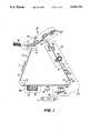
- FIG. 1is a schematic of an electrostatographic process machine, such as a copier or printer, including the mechanism of the present invention.
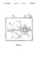
- FIG. 2is an enlarged schematic of the fusing apparatus and mechanism of the present invention.
- an electrostatographic reproduction apparatus or machine such as an optical copieris shown generally as 10.
- the apparatus 10includes an image-bearing member 11 which is an endless flexible belt which has a frontside image-bearing surface 12 divided into image frame areas.
- the member 11is shown as an endless flexible web, it should be understood that an image bearing member in the form of a rigid drum can be used instead.
- the member 11 as shownis trained about a series of rollers 13-16 for movement in the direction, for example, of the arrow T1.
- One of such rollers, for example, the roller 13,can be a drive roller for repeatedly moving the member 11 sequentially through a series of process stages shown, for example, as AA, BB, CC and DD.
- clean and charge-free image frame portions of the image-bearing member 11initially move through the stage AA where a charging device 20 uniformly charges the image-bearing surface (IBS) 12 with electrostatic charges to a first potential having a desired first polarity.
- the electrostatic charges on the IBS 12are then used in one manner or another (as is well known in the art) to electrostatically form, on each image frame portion of the surface 12, a latent image pattern of an original document.
- such an image patterncan be formed by selectively discharging areas of the uniformly charged image frame portion of the surface 12, for example, to a second desired potential.
- Such selective dischargingcan be achieved, for example, using an electronic printhead 22 or the like, and/or using an optical system as shown partially.
- a typical optical systemincludes a light source (not shown) that illuminates a document sheet. The light rays reflected from the document sheet can then be reflected by a mirror shown as 24, through a lens 26, and onto the surface 12 for such optical imaging.
- the copier or printer 10includes a suitable device such as an electrometer 27 that is capable of measuring and summing or integrating up the quantity of charge remaining on each image-wise discharged image frame portion following such selective discharge.
- the electrometermay be used to determine the average level of charge over the area of each image frame.
- the copier or printer 10also includes a logic and control unit 28 that includes means coupled to the electrometer, for example, for comparing the charge measurement by the device 27 against a predetermined average or standard charge value that can be stored as part of the control programs of the LCU 28.
- the logic and control unit (LCU) 28is used for controlling the functions of the various stations and components of the electrostatographic copier or printer 10 based, for example, on the sensed instantaneous location of the moving image-bearing member 11.
- the LCU 28for example has a digital computer, preferably a microprocessor which includes stored programs that are responsive to sensed input signals for sequentially actuating and deactuating the various process stations and components of the copier or printer 10, as well as for controlling the various functions of each such station and component.
- the image-bearing memberfor example, may have perforations for indicating the locations of image frames. Additional encoding means may be provided as known in the art for providing desired precise timing signals for the control of the various functions and components. Programming of a number of commercially available microprocessors such as an INTEL Model 8086 Microprocessor (which along with others can be used in the LCU 28 according to the present invention) is a conventional skill in the art.
- the stage BBaccordingly therefore includes a development apparatus 30 that contains a two-component developer material 31 which comprises for example magnetizable carrier particles, and the charged toner particles for such development of the image pattern on the surface 12.
- a development apparatus 30that contains a two-component developer material 31 which comprises for example magnetizable carrier particles, and the charged toner particles for such development of the image pattern on the surface 12.
- stage CCincludes an image transfer station 33 where the visible toner image on the image frame is transferred to a surface of a suitable receiver sheet, such as a sheet of plain paper, which is fed in registration to the station 33 from a supply 32 thereof along a sheet travel path.
- a suitable receiver sheetsuch as a sheet of plain paper
- the copy sheetthen travels to the fusing station of the present invention shown generally as 35.
- the fusing station 35the toner image on the sheet is permanently fused to such sheet, thereby forming a hard copy.
- the used portion of the surface 12, from which the toner image was transferredis moved on towards the initial stage AA to again begin another imaging cycle.
- the surface 12is cleaned before it is again reused. Such cleaning is carried out at the stage DD where the residual charges are removed by a discharge lamp 34 and/or neutralized by a corona 36, and the residual particles are removed by a cleaning means or apparatus shown, for example, as 40.
- the fusing station 35 of the present inventionis shown in greater detail. As a process station of the copier or printer 10, the fusing station 35 and all its components are therefore under the control of the LCU 28. As shown, the station 35 includes a fusing apparatus 42, and the post-fusing decurling mechanism of the present invention shown generally as 44.
- the fusing apparatus 42includes a hard pressure roller 46 that is rotatable for example in the direction of the arrow 47, and that forms a fusing nip 48 with a heated soft surface fuser roller 50.
- the hard pressure roller 46is made of a metallic shell, and the softer fuser roller 50 will have an elastomeric outer layer.
- Conventional meansare provided for urging the rollers 46, 50 towards each other.
- the fuser roller 50can be heated externally, or as shown internally by means such as a heat lamp 52.
- the fuser roller 50is rotatable for example in the direction of the arrow 53 so as to cooperate with the pressure roller 46, to feed a receiver sheet S, which is carrying toner images 54 thereon, through the fusing nip 48.
- the sheet Sis fed as such so that the heated fuser roller 50 directly contacts the toner images 54 on the image side 56 of the sheet S. Consequently, during such feeding the hard pressure roller 46 directly contacts the back side 57 of the sheet S.
- the hard pressure roller 46presses through the back 57 of the sheet such as to create a dent or depression in the part of the soft surface 58 of the fuser roller 50 that is in the nip 48 at any time.
- the effect of such pressing by the hard roller on the sheet Sis an undesirable convex curl induced in the image side 56 of the sheet S as it exits the nip 48.
- one ordinary effect of the hard roller and soft roller nip pressure on the sheet Sis an undesirable backward curling tendency in such sheet S.
- Such backward curlingis more likely to occur in sheets that carry lightly toned images, that is, sheets that do not have a heavily toned image pattern thereon.
- sheets that carry heavily toned imagesfor example, sheets carrying continuous tone or half tone pictures or large solid areas, when fused as above, tend instead to exhibit an undesirable concave curl in the image side 56 of each such sheet.
- concave curlingoccurs particularly after the heated and fused toner image on the sheet cools, apparently thereby causing greater than ordinary surface contractions on the image side 56 of such sheet S.
- control meansthat include the charge measurement device 27 and the LCU 28.
- the device 27 with the aid of the LCU 28measures the quantity of charge remaining on each image frame portion of the initially uniformly charged image-bearing surface 12 following selective image-wise discharge.
- the degree of charged toner particle laydown on each such framecan thus be predicted from such measurements by comparing each measurement against a particular laydown at a predetermined or standard value of charge measurement.
- a predetermined or standard value of measured charge against which such predictions are to be madeshould be determined empirically for each machine.
- the device 27, LCU 28 and the post-fusing decurling mechanism 44are provided for removing undesirable convex and concave curls induced in the image side 56 of a receiver sheet S.
- the mechanism 44has first means shown as 60 which include a first rotatable hard roller 62 and a rotatable soft roller 64.
- the first hard roller 62is biased by conventional means such as 82B towards a soft roller 64 to form a first decurling nip 66 through which a sheet S exiting the fusing nip 48 can be fed.
- the sheet Sis fed therethrough such that the soft roller 64 which is dented or depressed by the hard roller 62, directly contacts the image-carrying side 56 thereof as such sheet is being subjected to decurling contact through such first decurling nip 66.
- Such decurling contact in the nip 66induces a desirable convex curl in the image-carrying side 56 of the sheet S because of the depression of the soft roller 64.
- an undesirable concave curl induced by the fusing apparatus 42 in the side 56 of sheet Scan be desirably removed by such decurling contact.
- a sheet S predicted by the means 27, 28 to be heavily tonedthat is, a sheet with a predicted heavier than standard toner laydown, will be selectively fed through the first decurling nip 66 in order to remove the undesirable concave curl that would be induced in the side 56 thereof after fusing.
- the decurling mechanism 44also has second means shown as 70 which include a second rotatable hard roller 72 that is also biased by conventional means such as 82A towards the rotatable soft roller 64.
- the second hard roller 72 and the soft roller 64form a second decurling nip 76 through which a sheet S exiting the fusing nip 48 can also be fed.
- the pressure of the second hard roller 72 on the soft roller 64also causes the soft roller 64 to dent or be depressed at the nip 76 as the soft roller 64 accommodates itself to the hard roller 72.
- the sheet Sis fed therethrough such that the second hard roller 72 directly contacts the image-carrying side 56 of the sheet as such sheet S is being subjected to decurling contact through such second decurling nip 76.
- Such decurling contact 76induces a desirable concave curl in the image-carrying side 56 of the sheet S.
- an undesirable convex curl previously induced in such side 56 by the fusing apparatus 42can be desirably removed by feeding such sheet S into such decurling contact.
- a sheet predicted by the means 27, 28 to be lightly toned, for example,will be fed through the second decurling nip 76 in order to remove the undesirable convex curl that ordinarily would be induced in the side 56 of such sheet during fusing.
- the method of the present invention for removing undesirable concave and convex curls induced in the image side of a receiver sheet fed through a heated fusing nip of the copier or printer 10includes the following steps.
- the first stepis measuring the quantity of charge on each image frame of the image-bearing surface following image-wise discharge, and comparing such measurement to a predetermined or standard value of charge measurement in order to predict whether the toner particle laydown on such a frame will be heavier or lighter than a laydown at such predetermined or standard charge value measurement.
- the next step which occurs after each sheet is fused,is to selectively deflect each such sheet, exiting the fusing nip 48, by a control means which is responsive to a signal from the LCU 28, and which means includes, for example, a sheet deflector 80.
- the sheet Sis selectively deflected into decurling contact through either the first decurling nip 66 or through the second decurling nip 76.
- the selective deflectionis such that a heavily toned sheet which would otherwise tend to curl concavely to the image side 56 is deflected through the first decurling nip 66, and a lightly toned sheet which would otherwise exhibit a convex curl in such image side 56 is deflected instead through the second decurling nip 76.
- the first means 60 and second means 70share the common soft roller 64 which consequently must be rotatable clockwise and counterclockwise.
- the roller 64for example can be the drive roller, and as such is coupled to drive means such as a motor M or to the main drive of the copier, and operated by a selectively actuated transmission arrangement for switching directions of rotations.
- the decurling mechanism 44includes decurling-nip loading means, shown as 82A, 82B for variably loading each hard roller 62, 72 against the soft roller 64. Under the control of the LCU 28, such variable loading means can operate such that the heavier the predicted toner laydown on a sheet S, for example, the greater the load in the first decurling nip 66.
- Modifications of the present inventionmay include the use, for example, of a densitometer for determining the degree of toner laydown on each image frame or sheet after development. As is known, this can be accomplished by measuring and comparing the reflectivity of the developed image frame or of a single side image-carrying sheet. Further modifications, for example, may include a decurling mechanism with a plurality of soft rollers and a single hard roller or other feasible combination thereof.
- the soft roller 64may have substantially the same softness and diameter of the fuser roller, or the softness and nip pressures of the mechanism 44 can be varied appropriately.
- an electrostatographic machinesuch as a copier or printer 10
- the curling removing mechanismincludes means for predicting the degree of toner laydown on each sheet, and for selectively feeding each sheet into decurling contact in either a first or a second decurling nip in order to remove undesirable concave or convex curls in the image side of the sheet.
Landscapes
- Physics & Mathematics (AREA)
- General Physics & Mathematics (AREA)
- Separation, Sorting, Adjustment, Or Bending Of Sheets To Be Conveyed (AREA)
Abstract
Description
Claims (16)
Priority Applications (1)
| Application Number | Priority Date | Filing Date | Title |
|---|---|---|---|
| US07/632,786US5084731A (en) | 1990-12-24 | 1990-12-24 | Sheet decurling mechanism and method |
Applications Claiming Priority (1)
| Application Number | Priority Date | Filing Date | Title |
|---|---|---|---|
| US07/632,786US5084731A (en) | 1990-12-24 | 1990-12-24 | Sheet decurling mechanism and method |
Publications (1)
| Publication Number | Publication Date |
|---|---|
| US5084731Atrue US5084731A (en) | 1992-01-28 |
Family
ID=24536934
Family Applications (1)
| Application Number | Title | Priority Date | Filing Date |
|---|---|---|---|
| US07/632,786Expired - Fee RelatedUS5084731A (en) | 1990-12-24 | 1990-12-24 | Sheet decurling mechanism and method |
Country Status (1)
| Country | Link |
|---|---|
| US (1) | US5084731A (en) |
Cited By (30)
| Publication number | Priority date | Publication date | Assignee | Title |
|---|---|---|---|---|
| US5153662A (en)* | 1992-04-06 | 1992-10-06 | Xerox Corporation | Sheet decurling apparatus |
| US5201514A (en)* | 1992-04-06 | 1993-04-13 | Xerox Corporation | Apparatus for decurling a sheet |
| US5237381A (en)* | 1991-01-23 | 1993-08-17 | Canon Kabushiki Kaisha | Sheet discharging apparatus with curl correcting means |
| US5258815A (en)* | 1989-07-04 | 1993-11-02 | Konica Corporation | Fixing apparatus |
| US5287157A (en)* | 1991-05-14 | 1994-02-15 | Fuji Xerox Co., Ltd. | Sheet straightening device |
| US5296904A (en)* | 1993-03-31 | 1994-03-22 | Xerox Corporation | Three-roll fuser with center pressure roll for black and color application |
| US5319426A (en)* | 1992-12-02 | 1994-06-07 | Eastman Kodak Company | Image forming apparatus having improved fusing consistency |
| US5357327A (en)* | 1992-04-06 | 1994-10-18 | Xerox Corporation | Sheet decurling system including cross-curl |
| US5396318A (en)* | 1992-12-11 | 1995-03-07 | Nec Corporation | Fixing device having a curl compensation capability |
| US5414503A (en)* | 1993-12-13 | 1995-05-09 | Xerox Corporation | Predictive decurler apparatus and method |
| US5442429A (en)* | 1992-09-30 | 1995-08-15 | Tr Systems Inc | Precuring apparatus and method for reducing voltage required to electrostatically material to an arcuate surface |
| US5515152A (en)* | 1994-10-03 | 1996-05-07 | Xerox Corporation | Multi-gate tandem decurler |
| US5519481A (en)* | 1994-10-11 | 1996-05-21 | Xerox Corporation | Adaptive decurler for selective decurling of localized image areas |
| US5539511A (en)* | 1994-12-16 | 1996-07-23 | Xerox Corporation | Multilevel/duplex image sheet decurling apparatus |
| US5548389A (en)* | 1994-12-19 | 1996-08-20 | Xerox Corporation | Variable position stripper system for curl reduction |
| US5749040A (en)* | 1995-07-20 | 1998-05-05 | Canon Kabushiki Kaisha | Image forming apparatus capable of correcting curl of sheet |
| US5787331A (en)* | 1994-12-14 | 1998-07-28 | Canon Kabushiki Kaisha | Curl correction device of an image forming apparatus |
| US5848347A (en)* | 1997-04-11 | 1998-12-08 | Xerox Corporation | Dual decurler and control mechanism therefor |
| US6002913A (en)* | 1998-11-05 | 1999-12-14 | Xerox Corporation | Xerographic fuser module with integral sheet decurler |
| US20030190176A1 (en)* | 2002-04-04 | 2003-10-09 | Konica Corporation | Fixing device and image forming apparatus equipped therewith |
| US20040042831A1 (en)* | 2002-08-29 | 2004-03-04 | Xerox Corporation | Quad-roll decurler |
| US6939279B2 (en) | 2001-05-01 | 2005-09-06 | Ten Cate Enbi | Tire for skew reducing roller |
| US20080061488A1 (en)* | 2006-09-12 | 2008-03-13 | Keyes Thomas C | Interposer having decurler |
| US20110182642A1 (en)* | 2010-01-27 | 2011-07-28 | Kyocera Mita Corporation | Image-forming apparatus and method for controlling image-forming apparatus |
| US20110236102A1 (en)* | 2010-03-25 | 2011-09-29 | Kyocera Mita Corporation | Sheet curl correction apparatus and image forming apparatus |
| WO2012054316A1 (en) | 2010-10-21 | 2012-04-26 | Eastman Kodak Company | Concurrently removing sheet charge and curl |
| US8320817B2 (en) | 2010-08-18 | 2012-11-27 | Eastman Kodak Company | Charge removal from a sheet |
| CN103207556A (en)* | 2012-01-16 | 2013-07-17 | 佳能精技股份有限公司 | Image Forming Apparatus |
| CN110398887A (en)* | 2018-04-24 | 2019-11-01 | 夏普株式会社 | Image forming device, recording medium and control method |
| JP2020016769A (en)* | 2018-07-26 | 2020-01-30 | 株式会社リコー | Fixing device and image forming device |
Citations (7)
| Publication number | Priority date | Publication date | Assignee | Title |
|---|---|---|---|---|
| US4326915A (en)* | 1979-11-15 | 1982-04-27 | Xerox Corporation | Sheet de-curler |
| US4505695A (en)* | 1983-04-18 | 1985-03-19 | Xerox Corporation | Sheet decurling mechanism |
| US4627718A (en)* | 1983-06-08 | 1986-12-09 | Xerox Corporation | Sheet curl control apparatus for a copier |
| US4632533A (en)* | 1985-04-01 | 1986-12-30 | Xerox Corporation | Off-set nip roll decurler |
| US4926358A (en)* | 1987-05-20 | 1990-05-15 | Ricoh Company, Ltd. | System for controlling curls of a paper |
| US4952281A (en)* | 1988-05-10 | 1990-08-28 | Kobayashi Engineering Works, Ltd. | Sheet curls reformer |
| US5005050A (en)* | 1989-06-15 | 1991-04-02 | Eastman Kodak Company | Control of toner particle charge |
- 1990
- 1990-12-24USUS07/632,786patent/US5084731A/ennot_activeExpired - Fee Related
Patent Citations (7)
| Publication number | Priority date | Publication date | Assignee | Title |
|---|---|---|---|---|
| US4326915A (en)* | 1979-11-15 | 1982-04-27 | Xerox Corporation | Sheet de-curler |
| US4505695A (en)* | 1983-04-18 | 1985-03-19 | Xerox Corporation | Sheet decurling mechanism |
| US4627718A (en)* | 1983-06-08 | 1986-12-09 | Xerox Corporation | Sheet curl control apparatus for a copier |
| US4632533A (en)* | 1985-04-01 | 1986-12-30 | Xerox Corporation | Off-set nip roll decurler |
| US4926358A (en)* | 1987-05-20 | 1990-05-15 | Ricoh Company, Ltd. | System for controlling curls of a paper |
| US4952281A (en)* | 1988-05-10 | 1990-08-28 | Kobayashi Engineering Works, Ltd. | Sheet curls reformer |
| US5005050A (en)* | 1989-06-15 | 1991-04-02 | Eastman Kodak Company | Control of toner particle charge |
Cited By (40)
| Publication number | Priority date | Publication date | Assignee | Title |
|---|---|---|---|---|
| US5258815A (en)* | 1989-07-04 | 1993-11-02 | Konica Corporation | Fixing apparatus |
| US5237381A (en)* | 1991-01-23 | 1993-08-17 | Canon Kabushiki Kaisha | Sheet discharging apparatus with curl correcting means |
| US5287157A (en)* | 1991-05-14 | 1994-02-15 | Fuji Xerox Co., Ltd. | Sheet straightening device |
| US5201514A (en)* | 1992-04-06 | 1993-04-13 | Xerox Corporation | Apparatus for decurling a sheet |
| US5153662A (en)* | 1992-04-06 | 1992-10-06 | Xerox Corporation | Sheet decurling apparatus |
| US5357327A (en)* | 1992-04-06 | 1994-10-18 | Xerox Corporation | Sheet decurling system including cross-curl |
| US5442429A (en)* | 1992-09-30 | 1995-08-15 | Tr Systems Inc | Precuring apparatus and method for reducing voltage required to electrostatically material to an arcuate surface |
| US5319426A (en)* | 1992-12-02 | 1994-06-07 | Eastman Kodak Company | Image forming apparatus having improved fusing consistency |
| US5396318A (en)* | 1992-12-11 | 1995-03-07 | Nec Corporation | Fixing device having a curl compensation capability |
| US5296904A (en)* | 1993-03-31 | 1994-03-22 | Xerox Corporation | Three-roll fuser with center pressure roll for black and color application |
| US5414503A (en)* | 1993-12-13 | 1995-05-09 | Xerox Corporation | Predictive decurler apparatus and method |
| US5515152A (en)* | 1994-10-03 | 1996-05-07 | Xerox Corporation | Multi-gate tandem decurler |
| US5519481A (en)* | 1994-10-11 | 1996-05-21 | Xerox Corporation | Adaptive decurler for selective decurling of localized image areas |
| US5787331A (en)* | 1994-12-14 | 1998-07-28 | Canon Kabushiki Kaisha | Curl correction device of an image forming apparatus |
| US5539511A (en)* | 1994-12-16 | 1996-07-23 | Xerox Corporation | Multilevel/duplex image sheet decurling apparatus |
| US5548389A (en)* | 1994-12-19 | 1996-08-20 | Xerox Corporation | Variable position stripper system for curl reduction |
| US5749040A (en)* | 1995-07-20 | 1998-05-05 | Canon Kabushiki Kaisha | Image forming apparatus capable of correcting curl of sheet |
| US5933698A (en)* | 1995-07-20 | 1999-08-03 | Canon Kabushiki Kaisha | Image forming apparatus capable of correcting curl of sheet |
| US5848347A (en)* | 1997-04-11 | 1998-12-08 | Xerox Corporation | Dual decurler and control mechanism therefor |
| US6002913A (en)* | 1998-11-05 | 1999-12-14 | Xerox Corporation | Xerographic fuser module with integral sheet decurler |
| US6939279B2 (en) | 2001-05-01 | 2005-09-06 | Ten Cate Enbi | Tire for skew reducing roller |
| US20030190176A1 (en)* | 2002-04-04 | 2003-10-09 | Konica Corporation | Fixing device and image forming apparatus equipped therewith |
| US7062218B2 (en)* | 2002-08-29 | 2006-06-13 | Xerox Corporation | Quad-roll decurler |
| US20040042831A1 (en)* | 2002-08-29 | 2004-03-04 | Xerox Corporation | Quad-roll decurler |
| US20080061488A1 (en)* | 2006-09-12 | 2008-03-13 | Keyes Thomas C | Interposer having decurler |
| US8544386B2 (en) | 2006-09-12 | 2013-10-01 | Xerox Corporation | Interposer having decurler |
| US20110182642A1 (en)* | 2010-01-27 | 2011-07-28 | Kyocera Mita Corporation | Image-forming apparatus and method for controlling image-forming apparatus |
| US8588674B2 (en)* | 2010-01-27 | 2013-11-19 | Kyocera Document Solutions, Inc. | Image-forming apparatus and method for controlling image-forming apparatus |
| US9229410B2 (en) | 2010-03-25 | 2016-01-05 | Kyocera Document Solutions Inc. | Sheet curl correction apparatus and image forming apparatus |
| US20110236102A1 (en)* | 2010-03-25 | 2011-09-29 | Kyocera Mita Corporation | Sheet curl correction apparatus and image forming apparatus |
| US9229411B2 (en) | 2010-03-25 | 2016-01-05 | Kyocera Document Solutions Inc. | Sheet curl correction apparatus and image forming apparatus |
| US8862047B2 (en)* | 2010-03-25 | 2014-10-14 | Kyocera Document Solutions Inc. | Sheet curl correction apparatus and image forming apparatus |
| US8320817B2 (en) | 2010-08-18 | 2012-11-27 | Eastman Kodak Company | Charge removal from a sheet |
| WO2012054316A1 (en) | 2010-10-21 | 2012-04-26 | Eastman Kodak Company | Concurrently removing sheet charge and curl |
| US20130183059A1 (en)* | 2012-01-16 | 2013-07-18 | Canon Finetech Inc. | Image forming apparatus |
| US8989614B2 (en)* | 2012-01-16 | 2015-03-24 | Canon Finetech, Inc. | Image forming apparatus including a temperature difference providing unit providing a relative temperature difference for a conveyed sheet |
| CN103207556A (en)* | 2012-01-16 | 2013-07-17 | 佳能精技股份有限公司 | Image Forming Apparatus |
| CN103207556B (en)* | 2012-01-16 | 2016-03-23 | 佳能精技股份有限公司 | Image processing system |
| CN110398887A (en)* | 2018-04-24 | 2019-11-01 | 夏普株式会社 | Image forming device, recording medium and control method |
| JP2020016769A (en)* | 2018-07-26 | 2020-01-30 | 株式会社リコー | Fixing device and image forming device |
Similar Documents
| Publication | Publication Date | Title |
|---|---|---|
| US5084731A (en) | Sheet decurling mechanism and method | |
| JP5954018B2 (en) | Image forming apparatus | |
| US4039257A (en) | Pretransfer corotron switching | |
| US4191465A (en) | Apparatus for producing simplex of duplex copies | |
| JPS6358374A (en) | Image forming method | |
| US4080053A (en) | Transfer apparatus and method | |
| US5079597A (en) | Cleaning method and apparatus for intermediate transfer member | |
| US3743403A (en) | Transport assembly | |
| JPH103191A5 (en) | ||
| US3795441A (en) | Transfer roller | |
| US5576824A (en) | Five cycle image on image printing architecture | |
| US3751155A (en) | Pre-development exposure assembly | |
| US5835831A (en) | Reproduction apparatus image transfer control for preventing fuser oil contamination defects | |
| JP2004029217A (en) | Write correction method for image forming apparatus and image forming apparatus | |
| JPS6229324B2 (en) | ||
| JP2569163B2 (en) | Electrostatographic copier | |
| US4339194A (en) | Cold pressure fusing apparatus | |
| US3770346A (en) | Method and apparatus for fuser assembly cooling in an electrostatographic machine | |
| JPH07210020A (en) | Heating and pressurization fuser and fixing method | |
| US3901186A (en) | Transfer roller assembly | |
| US5136337A (en) | Electrostatographic apparatus and method having a fixing dwell time extending device | |
| US7424246B2 (en) | Toner imaging machine having an external fusing module | |
| US5177550A (en) | Fixing apparatus having a releasant removal means | |
| EP0416895B1 (en) | Electrostatographic apparatus | |
| US6349190B1 (en) | Low cost process multicolor image reproduction machine |
Legal Events
| Date | Code | Title | Description |
|---|---|---|---|
| FEPP | Fee payment procedure | Free format text:PAYOR NUMBER ASSIGNED (ORIGINAL EVENT CODE: ASPN); ENTITY STATUS OF PATENT OWNER: LARGE ENTITY | |
| AS | Assignment | Owner name:EASTMAN KODAK COMPANY, ROCHESTER, NY A CORP. OF NJ Free format text:ASSIGNMENT OF ASSIGNORS INTEREST.;ASSIGNOR:BARUCH, SUSAN C.;REEL/FRAME:005564/0767 Effective date:19901220 | |
| CC | Certificate of correction | ||
| FPAY | Fee payment | Year of fee payment:4 | |
| FEPP | Fee payment procedure | Free format text:PAYER NUMBER DE-ASSIGNED (ORIGINAL EVENT CODE: RMPN); ENTITY STATUS OF PATENT OWNER: LARGE ENTITY Free format text:PAYOR NUMBER ASSIGNED (ORIGINAL EVENT CODE: ASPN); ENTITY STATUS OF PATENT OWNER: LARGE ENTITY | |
| FPAY | Fee payment | Year of fee payment:8 | |
| FEPP | Fee payment procedure | Free format text:PAYER NUMBER DE-ASSIGNED (ORIGINAL EVENT CODE: RMPN); ENTITY STATUS OF PATENT OWNER: LARGE ENTITY Free format text:PAYOR NUMBER ASSIGNED (ORIGINAL EVENT CODE: ASPN); ENTITY STATUS OF PATENT OWNER: LARGE ENTITY | |
| AS | Assignment | Owner name:NEXPRESS SOLUTIONS LLC, NEW YORK Free format text:ASSIGNMENT OF ASSIGNORS INTEREST;ASSIGNOR:EASTMAN KODAK COMPANY;REEL/FRAME:012036/0959 Effective date:20000717 | |
| REMI | Maintenance fee reminder mailed | ||
| LAPS | Lapse for failure to pay maintenance fees | ||
| FP | Lapsed due to failure to pay maintenance fee | Effective date:20040128 | |
| STCH | Information on status: patent discontinuation | Free format text:PATENT EXPIRED DUE TO NONPAYMENT OF MAINTENANCE FEES UNDER 37 CFR 1.362 |