US5083976A - Adjustment of a shear bar using an air-borne sound detector - Google Patents
Adjustment of a shear bar using an air-borne sound detectorDownload PDFInfo
- Publication number
- US5083976A US5083976AUS07/603,608US60360890AUS5083976AUS 5083976 AUS5083976 AUS 5083976AUS 60360890 AUS60360890 AUS 60360890AUS 5083976 AUS5083976 AUS 5083976A
- Authority
- US
- United States
- Prior art keywords
- shear bar
- microphone
- impacts
- knives
- cutterhead
- Prior art date
- Legal status (The legal status is an assumption and is not a legal conclusion. Google has not performed a legal analysis and makes no representation as to the accuracy of the status listed.)
- Expired - Lifetime
Links
- 230000007246mechanismEffects0.000claimsabstractdescription23
- 239000004459forageSubstances0.000claimsabstractdescription14
- 230000004044responseEffects0.000claimsabstractdescription5
- 239000000463materialSubstances0.000claimsdescription23
- 238000000034methodMethods0.000claimsdescription13
- 230000000007visual effectEffects0.000claimsdescription4
- 230000001902propagating effectEffects0.000claims2
- 239000004575stoneSubstances0.000abstractdescription3
- 239000006096absorbing agentSubstances0.000description4
- 238000001514detection methodMethods0.000description4
- 239000002184metalSubstances0.000description3
- 230000035945sensitivityEffects0.000description3
- 238000010586diagramMethods0.000description2
- 238000003306harvestingMethods0.000description2
- 230000004048modificationEffects0.000description2
- 238000012986modificationMethods0.000description2
- 238000012360testing methodMethods0.000description2
- BQCIDUSAKPWEOX-UHFFFAOYSA-N1,1-DifluoroetheneChemical compoundFC(F)=CBQCIDUSAKPWEOX-UHFFFAOYSA-N0.000description1
- 229920006370KynarPolymers0.000description1
- 239000002033PVDF binderSubstances0.000description1
- 235000014676Phragmites communisNutrition0.000description1
- 230000035508accumulationEffects0.000description1
- 238000009825accumulationMethods0.000description1
- 230000008901benefitEffects0.000description1
- 230000002457bidirectional effectEffects0.000description1
- 238000013461designMethods0.000description1
- 239000000428dustSubstances0.000description1
- 230000007613environmental effectEffects0.000description1
- 230000003116impacting effectEffects0.000description1
- 230000003287optical effectEffects0.000description1
- 229920002981polyvinylidene fluoridePolymers0.000description1
- 238000012545processingMethods0.000description1
- 238000006467substitution reactionMethods0.000description1
- 239000010409thin filmSubstances0.000description1
Images

Classifications
- A—HUMAN NECESSITIES
- A01—AGRICULTURE; FORESTRY; ANIMAL HUSBANDRY; HUNTING; TRAPPING; FISHING
- A01F—PROCESSING OF HARVESTED PRODUCE; HAY OR STRAW PRESSES; DEVICES FOR STORING AGRICULTURAL OR HORTICULTURAL PRODUCE
- A01F29/00—Cutting apparatus specially adapted for cutting hay, straw or the like
- A01F29/09—Details
- A—HUMAN NECESSITIES
- A01—AGRICULTURE; FORESTRY; ANIMAL HUSBANDRY; HUNTING; TRAPPING; FISHING
- A01D—HARVESTING; MOWING
- A01D75/00—Accessories for harvesters or mowers
- A01D75/18—Safety devices for parts of the machines
- A01D75/187—Removing foreign objects
- Y—GENERAL TAGGING OF NEW TECHNOLOGICAL DEVELOPMENTS; GENERAL TAGGING OF CROSS-SECTIONAL TECHNOLOGIES SPANNING OVER SEVERAL SECTIONS OF THE IPC; TECHNICAL SUBJECTS COVERED BY FORMER USPC CROSS-REFERENCE ART COLLECTIONS [XRACs] AND DIGESTS
- Y10—TECHNICAL SUBJECTS COVERED BY FORMER USPC
- Y10S—TECHNICAL SUBJECTS COVERED BY FORMER USPC CROSS-REFERENCE ART COLLECTIONS [XRACs] AND DIGESTS
- Y10S56/00—Harvesters
- Y10S56/02—Methods
- Y—GENERAL TAGGING OF NEW TECHNOLOGICAL DEVELOPMENTS; GENERAL TAGGING OF CROSS-SECTIONAL TECHNOLOGIES SPANNING OVER SEVERAL SECTIONS OF THE IPC; TECHNICAL SUBJECTS COVERED BY FORMER USPC CROSS-REFERENCE ART COLLECTIONS [XRACs] AND DIGESTS
- Y10—TECHNICAL SUBJECTS COVERED BY FORMER USPC
- Y10S—TECHNICAL SUBJECTS COVERED BY FORMER USPC CROSS-REFERENCE ART COLLECTIONS [XRACs] AND DIGESTS
- Y10S56/00—Harvesters
- Y10S56/15—Condition responsive
Definitions
- the present inventionrelates to a method for adjusting the position of a shear bar relative to a rotating cutterhead in agricultural harvesting equipment. More particularly, contact between the shear bar and the rotating cutterhead is detected by a detector which detects the air-borne sound waves resulting from such contact, the detector producing output signals to control an automatic shear bar adjusting system, or aid an operator in setting the shear bar.
- Johnson U.S. Pat. Nos. 4,934,612 and 4,843,767disclose a forage harvester having an automatic shear bar adjusting system wherein two knock sensors sense mechanical vibrations induced in a shear bar support as a result of contact between the shear bar and the knives of a rotating cutterhead, the sensors producing output signals to a microprocessor which in turn controls two motors to adjust the position of the shear bar relative to the cutterhead.
- a "knock sense" routineis called, the outputs of both knock sensors are tested and it is assumed that a knock has occurred if the output of either knock sensor exceeds a threshold level for at least some minimum percentage of the time interval during which the sensor outputs are tested.
- Weaver et.al. U.S. Pat. No. 4,799,625discloses a shear bar adjusting system similar to that of the Johnson patent, but having only one knock sensor.
- Weaver et.al.employs a "get noise" routine which is called each time a shear bar adjust routine is executed.
- the get noise routineis employed to obtain an indication of noise vibrations induced in the sensor by normal harvester operation, this indication being used in the shear bar adjust routine to set the sensitivity of the control system to the output of the knock sensor.
- the get noise routineincludes a "test generator” subroutine which actuates a knocker and samples the output of the knock sensor, thus testing the operability of the knock sensor.
- shear bar adjusting systemsemploying mechanical vibration sensors must employ special apparatus or procedures to compensate for the unreliability of such sensors and their sensitivity to vibrations induced in the shear bar by normal harvester operation.
- An object of the present inventionis to provide a method and apparatus for detecting contact between a shear bar and the knives of a rotating cutterhead by sensing air-borne sound waves produced by such contact.
- An object of the present inventionis to provide a sensor for sensing air-borne sound waves produced by contact of a shear bar with the knives of a rotating cutterhead, the sensor preferably being mounted inside a feed roll which feeds material toward the cutterhead.
- An object of the present inventionis to provide a sensor for sensing air-borne sound waves produced when the knives of a rotating cutterhead contact a shear bar, the sensor being mounted on a vibration absorber so as to isolate it from mechanical vibrations occurring in the support for the vibration absorber.
- a further object of the inventionis to provide a circuit for controlling the adjustment of a shear bar relative to a rotating cutterhead by detecting air-borne sound waves produced by impacts of the cutterhead on the shear bar, the circuit also controlling a material feed mechanism to stop the feed mechanism upon detection of air-borne sound waves produced by impacts of hard materials on the feed mechanism, the circuit performing both functions in response to output signals produced by a single sensor.
- a forage harvester of conventional designand including a shear bar, a rotatable cutterhead and a system for adjusting the position of the shear bar relative to the cutterhead by sensing contact between the two as the shear bar is moved, is provided with a microphone for sensing air-borne sounds produced when the rotating cutterhead contacts the shear bar.
- the microphoneis preferably mounted inside a hollow feed roll which feeds crop material to the cutterhead.
- the microphoneis mounted on a vibration absorber which is in turn supported inside the feed roll, the vibration absorber serving to isolate the microphone from any vibrations which may occur in the support.
- the microphoneproduces output signals which are applied to a filter, the output of the filter being digitized and applied to a microprocessor which controls two motors for moving the ends of the shear bar relative to the cutterhead.
- the microprocessoris also programmed to control stopping of the feed mechanism when the microphone detects the impact of a hard object on the feed mechanism and in this embodiment the filter is a programmable band-pass filter controlled by the microprocessor to pass signals having frequencies characteristic of shear bar/cutterhead impacts or, alternatively, to pass signals having frequencies characteristic of the impact of hard objects on the feed mechanism.
- FIG. 1is a schematic side view of a forage harvester in which the invention may be used;
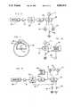
- FIG. 2schematically illustrates a system for automatically adjusting a shear bar relative to the knives of a rotating cutterhead
- FIG. 3is a schematic block diagram of a circuit for producing signals for adjusting a shear bar
- FIG. 3Aillustrates a modification of the circuit of FIG. 3 suitable for use in a system wherein an operator manually adjusts a shear bar relative to a cutterhead;
- FIG. 4is a diagrammatic illustration of a microphone mounted within a rotatable feed roll.
- FIG. 5is a schematic block diagram of a circuit having a single microphone for detecting either impacts of a rotating cutterhead on a shear bar or impacts of hard objects on a feed mechanism.
- FIG. 1illustrates a forage harvesting machine of the type in which the present invention may be employed. It is apparent that the invention may also be employed with benefit for adjustment of a shear bar relative to a rotating cutterhead in other types of farm equipment and other machinery.
- the representative farm machine illustrated in FIG. 1may be similar to the forage harvester in U.S. Pat. Nos. 3,523,411 to Waldrop et.al. and 3,959,953 to Garrott.
- the forage harvestergenerally designated by reference numeral 10, comprises a base unit 11 and an attachment 12 for gathering crop material and feeding it to the base unit for processing.
- Attachment 12directly cuts crop material in the field and feeds it to base unit 11 where it is chopped and eventually conveyed to a trailing forage wagon (not shown).
- a direct cut attachmentis shown for exemplary purposes but in actual practice any type of attachment, e.g., a row crop unit or a windrow pickup, could be used with a base unit of the type shown insofar as the present invention is concerned.
- the attachment shownincludes a reel 13, depicted in phantom, which operates in a conventional manner to guide material over a cutter bar 14 and up an inclined floor 15 to a consolidating auger 16, also depicted in phantom outline.
- Attachment 12is pivotally mounted to base unit 11 at 17 and is adapted to feed crop material to the space between upper and lower front reed rolls 18, 20 and then on to upper and lower rear feed rolls 21, 22 which in turn feed material to a cutterhead 23 (shown in phantom) which chops the crop material and guides it rearwardly to conveyor means 24 in a well known manner.
- the conveyor 24commonly comprises an auger mounted transversely for feeding the chopped crop material to a blower unit which conveys it upwardly via a vertical spout 25 (partially shown) and then rearwardly to a trailing forage wagon.
- the front and rear pairs of upper and lower feed rollscompress into a mat-like configuration the crop material which has been gathered by the attachment and consolidated by auger 16.
- the mat of materialis fed rearwardly across the top surface of a shearbar 26 which is operatively associated with a series of cutting elements or knives 27 (one of which is shown in phantom) on rotating cutterhead 23.
- the cutterheadis journaled for rotation by mounting assembly 28 in a sidewall 30 of base unit 11. There are two sidewalls 30, one at each side of the crop feed path for defining the lateral extent of the feed path, and cutterhead 23 is journaled for rotation by a mounting assembly 28 in each sidewall.
- two bidirectional motors 110 and 112are provided for adjusting the position of shear bar 26 relative to the cutterhead 23.
- the shear baris movably mounted on a fixed shear bar support 104 in a manner well known in the art.
- Motor 110drives a lead screw 106 which is linked to one end (A) of shear bar 23 to move end A of the shear bar relative to the support 104 and the cutterhead 23.
- motor 112drives a lead screw 108 which is linked to end B of the shear bar to move end B relative to support 104 and the cutterhead 23.
- U.S. Pat. Nos. 4,678,130 and 4,436,248show suitable linkages driven by lead screws for moving the ends of a shear bar.
- a microprocessor-based electrical control circuit 116senses the output of a tachometer 114.
- the tachometerproduces an output signal proportional to the rate of rotation of cutterhead 23. If the cutterhead is rotating at more than a predetermined minimum speed, the output signal from the tachometer enables control circuit 116 to execute a sequence of steps during which it selectively energizes motors 110 and 112 to adjust the position of the shear bar 26 relative to the rotating cutterhead 23.
- the shear bar adjustment procedureis fully described in the aforementioned patent to Weaver et al.
- the procedurecomprises a sequence of steps which may briefly be summarized as follows.
- Step 1Energize motor 110 to move end A of the shear bar away from the cutterhead.
- Step 2Energize motor 112 to move end B of the shear bar away from the rotating cutterhead.
- Step 3Energize motor 110 to move end A of the shear bar toward the rotating cutterhead until contact is made between the shear bar and the knives of the cutterhead or until a fixed interval of time has elapsed, whichever occurs first.
- Step 4If step 3 is terminated because of contact, energize motor 110 for a short fixed interval to move end A of the shear bar away from the cutterhead a short distance. motor 112 to move end B of the shear bar toward the rotating cutterhead until contact is made between the shear bar and the knives of the cutterhead or until a fixed interval of time has elapsed, whichever occurs first.
- Step 6If step 5 is terminated because of contact, energize motor 112 for a short fixed interval to move end B of the shear bar away from the cutterhead a short distance.
- Step 7Repeat steps 3-6 until ends A and B of the shear bar contact the knives of the cutterhead on each of two separate energizations of the respective motors which move the ends.
- contact between the shear bar and the knives of the rotating cutterheadis sensed by a piezo-electric knock sensor which is mounted on the shear bar support 104 and senses vibrations induced in the support when a cutterhead knife contacts the shear bar 26.
- the control circuit 116repeatedly senses the output signal from the knock sensor to determine when contact has been made between a cutterhead knife and the shear bar.
- a microphone 102is used to sense the air-borne sound waves produced when the knives of the rotating cutterhead impact the shear bar 26.
- the microphoneis connected through an amplifier 118 to a band pass filter 120 which is designed to pass only signals in the frequency range characteristic of sound waves produced when the rotating cutterhead knives contact the shear bar. 1
- the microphonesenses all air-borne sound waves 100 impinging on it and produces an analog electrical output signal containing frequencies characteristic of the sound waves.
- the analog signalis amplified by amplifier 118 and applied to filter 120.
- the filterpasses on to its output 122 only those frequencies characteristic of the air-borne sound waves resulting from impacts of the cutterhead knives on the shear bar.
- the output of filter 120may be connected to an analog-to-digital converter 124 which is in turn connected to a microprocessor 126.
- the microprocessor 126samples the output of the converter 124 to determine when knife-shear bar contact occurs, and in response thereto issues signals to control motors 110 and 112 to accomplish the shear bar adjustment as described in the Weaver et.al. patent.
- the use of a microphone to sense air-borne sound waves rather than mechanical vibrations induced in the shear bar 26 or its support 104permits the positioning of the microphone at locations remote from the shear bar.
- the microphone 102therefore need not be subjected to the mechanical stresses and dirty environmental conditions that occur when a sensor is mounted on the shear bar or its support.
- the microphone 102may be mounted in any convenient location, such as on a side wall 30 or even on shear bar support 104 so long as it can sense the air-borne sounds produced by contact between the cutterhead knives and the shear bar and is isolated from vibrations which may occur in the mounting means. It is particularly advantageous to position the microphone within one of the feed rolls 18, 20, 21, 22 so as to protect it from moisture, dirt, and accumulations of crop material.
- the lower front feed rollcomprises a hollow cylinder having two end caps. One end cap is affixed to one end of the cylinder and driven by a splined drive shaft. The other end cap is affixed to the cylinder and is journaled for free rotation about a fixed stub shaft.
- This stub shaftcorresponds to the shaft 31 shown in FIG. 1.
- a housing 43may be mounted on shaft 31 inside the feed roll 20 to support the sensors and associated circuits comprising a magnetic metal detector and a hard object detector for detecting metal and hard objects in the crop material being fed through the forage harvester.
- the microphone 102may be mounted on the housing 43 as illustrated in FIG. 4. Alternatively, the microphone may be mounted on a bracket attached to housing 43 as illustrated in the aforementioned copending applications.
- the microphone 102may be of any type capable of sensing air-borne sound waves.
- the microphoneis mounted on a vibration absorbing pad 65 to insulate the microphone from mechanical vibrations.
- the related applications referenced aboveshow a microphone of this type mounted on housing 43 for the purpose of sensing stones and other hard objects in crop material being fed through the forage harvester, the output of the sensor being applied to a circuit which controls the stopping of the feed mechanism.
- FIG. 5shows a suitable circuit arrangement for this purpose.
- the circuit of FIG. 5includes a microphone 102 for sensing air-borne sound waves, an amplifier 118, a programmable band pass filter 120', an analog-to-digital converter 124, a microprocessor 126, a shear bar adjust switch 128 and a clutch switch 130.
- the clutch switch 130is closed when a clutch is engaged to drive the crop feed mechanism of the harvester.
- switch 130When switch 130 is actuated it causes microprocessor 126 to output a signal over lead 132 to program the filter 120' so that the filter passes only those frequencies in the range of frequencies produced when a stone or other hard object impacts a feed roll.
- the sound waves produced by the impactsare sensed by microphone 102, amplified by amplifier 118 and applied to the filter.
- the frequencies characteristic of the impact of a hard object on a feed rollare passed through the filter, digitized by A/D converter 124, and applied to the microprocessor 126.
- the microprocessorresponds to detection of a hard object by producing an output signal to a feed stop circuit 134 stop the crop feed mechanism as fully explained in the copending applications referenced above.
- the clutch switch 130also causes microprocessor 126 to ignore actuation of switch 128 or, if a shearbar adjustment is in progress, to terminate the adjustment procedure. This insures that shearbar adjustment cannot be initiated or carried out while crop material is being fed through the harvester. If clutch switch 130 is not actuated, momentary actuation of switch 128 causes the microprocessor to execute the adjustment routine for adjusting the shear bar relative to the cutterhead if the tachometer 114 produces a signal indicating that the cutterhead is rotating faster than a predetermined rate. During execution of the routine, the microprocessor controls filter 120' via lead 132 so that the filter will pass only frequencies characteristic of contacts between the shear bar and cutterhead, and the circuit functions in the same manner as the circuit of FIG. 3.
- the present inventionis admirably suited for use in automatic shear bar adjusting systems wherein the ends of the shear bar are driven by electric motors.
- shear bar adjusting systemssuch as those disclosed in U.S. Pat. Nos. 4,436,248 and 4,678,130 wherein the lead screws 106 and 108 are manually turned to adjust the shear bar.
- the microprocessor 126is programmed to energize an indicator means such as a visual indicator means 136 (FIG. 3A) to signal an operator when the cutterhead is impacting the shear bar.
- the visual indicatormay be energized by a control circuit 138 in response to output signals from microprocessor 126.
- the visual indicator means 136should be positioned on the harvester so as to be visible to the operator as he is adjusting the shear bar.
Landscapes
- Life Sciences & Earth Sciences (AREA)
- Environmental Sciences (AREA)
- Measurement Of Mechanical Vibrations Or Ultrasonic Waves (AREA)
Abstract
Description
Claims (13)
Priority Applications (1)
| Application Number | Priority Date | Filing Date | Title |
|---|---|---|---|
| US07/603,608US5083976A (en) | 1990-10-26 | 1990-10-26 | Adjustment of a shear bar using an air-borne sound detector |
Applications Claiming Priority (1)
| Application Number | Priority Date | Filing Date | Title |
|---|---|---|---|
| US07/603,608US5083976A (en) | 1990-10-26 | 1990-10-26 | Adjustment of a shear bar using an air-borne sound detector |
Publications (1)
| Publication Number | Publication Date |
|---|---|
| US5083976Atrue US5083976A (en) | 1992-01-28 |
Family
ID=24416174
Family Applications (1)
| Application Number | Title | Priority Date | Filing Date |
|---|---|---|---|
| US07/603,608Expired - LifetimeUS5083976A (en) | 1990-10-26 | 1990-10-26 | Adjustment of a shear bar using an air-borne sound detector |
Country Status (1)
| Country | Link |
|---|---|
| US (1) | US5083976A (en) |
Cited By (23)
| Publication number | Priority date | Publication date | Assignee | Title |
|---|---|---|---|---|
| EP0649591A1 (en)* | 1993-10-20 | 1995-04-26 | CLAAS Kommanditgesellschaft auf Aktien | Security device for a shear bar adjusting mechanism |
| EP0734646A1 (en)* | 1995-03-31 | 1996-10-02 | New Holland Belgium N.V. | Method for moving a member towards a fixed stop in a forage harvester |
| US5819512A (en)* | 1997-03-20 | 1998-10-13 | Dickey-John Corporation | Apparatus and method for sensing material build-up |
| WO1998047345A1 (en)* | 1997-04-18 | 1998-10-29 | Case Harvesting Systems Gmbh | Method and device for measuring a gap in agricultural machines |
| US5913801A (en)* | 1995-11-22 | 1999-06-22 | Robert Bosch Gmbh | Agricultural baler, and method of baling |
| EP1044596A3 (en)* | 1999-04-12 | 2002-04-10 | New Holland Belgium N.V. | Alarm system for agricultural equipment |
| EP1402768A1 (en)* | 2002-09-06 | 2004-03-31 | Deere & Company | Detecting device to detect a jam in a harvesting machine |
| US20040216439A1 (en)* | 2003-04-30 | 2004-11-04 | Poulson Eric Alan | Method and apparatus for setting and maintaining reel-to-bedknife clearance |
| US20040216438A1 (en)* | 2003-04-30 | 2004-11-04 | Poulson Eric Alan | Height-of-cut adjustment system for reel mower |
| US20040216436A1 (en)* | 2003-04-30 | 2004-11-04 | Schmidt Mark Alvin | Cutting reel adjusting system |
| US20050005586A1 (en)* | 2003-07-10 | 2005-01-13 | Schmidt Mark Alvin | User interface and control for cutting reel system |
| US6878237B2 (en)* | 2002-03-27 | 2005-04-12 | Voith Paper Patent Gmbh | Machine and process for operating a machine to monitor vibrations |
| US20050159801A1 (en)* | 2004-01-16 | 2005-07-21 | Medtronic, Inc. | Novel implantable lead including sensor |
| US20070227111A1 (en)* | 2006-03-29 | 2007-10-04 | Deere & Company, A Delaware Corporation | Method for adjusting reel-to-bedknife clearance |
| US20070227110A1 (en)* | 2006-03-29 | 2007-10-04 | Deere & Company, A Delaware Corporation | Adaptive threshold technique for detecting reel-to-bedknife contact |
| US20080083205A1 (en)* | 2006-10-10 | 2008-04-10 | Textron Inc. | Method Of Bedknife Adjustment Using An Acoustical Sensor |
| US20090237227A1 (en)* | 2008-03-24 | 2009-09-24 | Ehrhart Philip J | Cutterbar failure detection system and method |
| EP1221280B2 (en)† | 2001-01-08 | 2011-07-27 | Deere & Company | Device to monitor the function of a working machine |
| US20120055135A1 (en)* | 2010-09-07 | 2012-03-08 | Steffen Brockhan-Luedemann | Cutting device |
| US10064332B1 (en) | 2017-03-06 | 2018-09-04 | Cnh Industrial America Llc | Monitor for slip clutches |
| US10993370B2 (en)* | 2017-11-06 | 2021-05-04 | Müthing GmbH & Co. KG | Agricultural working device |
| EP3837960A1 (en)* | 2019-12-19 | 2021-06-23 | Deere & Company | Forage harvester with processing component protection |
| EP4268566A1 (en)* | 2022-04-29 | 2023-11-01 | CNH Industrial Belgium N.V. | A system and method for monitoring the condition of the cutting knives of a combine header |
Citations (5)
| Publication number | Priority date | Publication date | Assignee | Title |
|---|---|---|---|---|
| US4205797A (en)* | 1978-10-30 | 1980-06-03 | Sperry Corporation | Magnetic clearance sensor |
| US4290255A (en)* | 1980-10-01 | 1981-09-22 | Sperry Corporation | Feed roll apparatus |
| US4799625A (en)* | 1987-05-05 | 1989-01-24 | Ford New Holland, Inc. | Method and apparatus for adjusting a shear bar relative to a cutter head |
| US4843767A (en)* | 1988-03-28 | 1989-07-04 | Deere & Company | Automatic forage harvester knife sharpening system |
| US4934612A (en)* | 1988-03-28 | 1990-06-19 | Deere & Company | Automatic forage harvester shearbar adjusting |
- 1990
- 1990-10-26USUS07/603,608patent/US5083976A/ennot_activeExpired - Lifetime
Patent Citations (5)
| Publication number | Priority date | Publication date | Assignee | Title |
|---|---|---|---|---|
| US4205797A (en)* | 1978-10-30 | 1980-06-03 | Sperry Corporation | Magnetic clearance sensor |
| US4290255A (en)* | 1980-10-01 | 1981-09-22 | Sperry Corporation | Feed roll apparatus |
| US4799625A (en)* | 1987-05-05 | 1989-01-24 | Ford New Holland, Inc. | Method and apparatus for adjusting a shear bar relative to a cutter head |
| US4843767A (en)* | 1988-03-28 | 1989-07-04 | Deere & Company | Automatic forage harvester knife sharpening system |
| US4934612A (en)* | 1988-03-28 | 1990-06-19 | Deere & Company | Automatic forage harvester shearbar adjusting |
Cited By (40)
| Publication number | Priority date | Publication date | Assignee | Title |
|---|---|---|---|---|
| EP0649591A1 (en)* | 1993-10-20 | 1995-04-26 | CLAAS Kommanditgesellschaft auf Aktien | Security device for a shear bar adjusting mechanism |
| EP0734646A1 (en)* | 1995-03-31 | 1996-10-02 | New Holland Belgium N.V. | Method for moving a member towards a fixed stop in a forage harvester |
| US5704199A (en)* | 1995-03-31 | 1998-01-06 | New Holland North America, Inc. | Method for moving a shearbar in a forage harvester |
| US5913801A (en)* | 1995-11-22 | 1999-06-22 | Robert Bosch Gmbh | Agricultural baler, and method of baling |
| US5819512A (en)* | 1997-03-20 | 1998-10-13 | Dickey-John Corporation | Apparatus and method for sensing material build-up |
| WO1998047345A1 (en)* | 1997-04-18 | 1998-10-29 | Case Harvesting Systems Gmbh | Method and device for measuring a gap in agricultural machines |
| EP1044596A3 (en)* | 1999-04-12 | 2002-04-10 | New Holland Belgium N.V. | Alarm system for agricultural equipment |
| EP1221280B2 (en)† | 2001-01-08 | 2011-07-27 | Deere & Company | Device to monitor the function of a working machine |
| US6878237B2 (en)* | 2002-03-27 | 2005-04-12 | Voith Paper Patent Gmbh | Machine and process for operating a machine to monitor vibrations |
| EP1402768A1 (en)* | 2002-09-06 | 2004-03-31 | Deere & Company | Detecting device to detect a jam in a harvesting machine |
| US6843044B2 (en) | 2002-09-06 | 2005-01-18 | Deere & Company | Detection arrangement for the detection of a crop jam in a harvesting machine |
| US20040216436A1 (en)* | 2003-04-30 | 2004-11-04 | Schmidt Mark Alvin | Cutting reel adjusting system |
| US7377092B2 (en)* | 2003-04-30 | 2008-05-27 | Deere & Company | Cutting reel adjusting system |
| US20040216438A1 (en)* | 2003-04-30 | 2004-11-04 | Poulson Eric Alan | Height-of-cut adjustment system for reel mower |
| US20040216439A1 (en)* | 2003-04-30 | 2004-11-04 | Poulson Eric Alan | Method and apparatus for setting and maintaining reel-to-bedknife clearance |
| US7114318B2 (en)* | 2003-04-30 | 2006-10-03 | Deere & Company | Height-of-cut adjustment system for reel mower |
| US7121073B2 (en)* | 2003-04-30 | 2006-10-17 | Deere & Company | Cutting reel adjusting system |
| US20070074498A1 (en)* | 2003-04-30 | 2007-04-05 | Schmidt Mark A | Cutting reel adjusting system |
| US7231757B2 (en)* | 2003-04-30 | 2007-06-19 | Deere & Company | Method and apparatus for setting and maintaining reel-to-bedknife clearance |
| AU2004200520B8 (en)* | 2003-04-30 | 2010-07-22 | Deere & Company | Cutting reel adjusting system |
| AU2004200520B2 (en)* | 2003-04-30 | 2010-07-01 | Deere & Company | Cutting reel adjusting system |
| AU2004200521B2 (en)* | 2003-04-30 | 2010-05-27 | Deere & Company | Method and apparatus for setting and maintaining reel-to-bedknife clearance |
| US20080184690A1 (en)* | 2003-04-30 | 2008-08-07 | Eric Alan Poulson | Cutting reel adjusting system |
| US7788892B2 (en) | 2003-07-10 | 2010-09-07 | Deere & Company | User interface and control for cutting reel system |
| US20050005586A1 (en)* | 2003-07-10 | 2005-01-13 | Schmidt Mark Alvin | User interface and control for cutting reel system |
| US20050159801A1 (en)* | 2004-01-16 | 2005-07-21 | Medtronic, Inc. | Novel implantable lead including sensor |
| US20070227110A1 (en)* | 2006-03-29 | 2007-10-04 | Deere & Company, A Delaware Corporation | Adaptive threshold technique for detecting reel-to-bedknife contact |
| US7353644B2 (en)* | 2006-03-29 | 2008-04-08 | Deere & Company | Method for adjusting reel-to-bedknife clearance |
| US7370461B2 (en)* | 2006-03-29 | 2008-05-13 | Deere & Company | Adaptive threshold technique for detecting reel-to-bedknife contact |
| US20070227111A1 (en)* | 2006-03-29 | 2007-10-04 | Deere & Company, A Delaware Corporation | Method for adjusting reel-to-bedknife clearance |
| US20080083205A1 (en)* | 2006-10-10 | 2008-04-10 | Textron Inc. | Method Of Bedknife Adjustment Using An Acoustical Sensor |
| US20090237227A1 (en)* | 2008-03-24 | 2009-09-24 | Ehrhart Philip J | Cutterbar failure detection system and method |
| US7973654B2 (en) | 2008-03-24 | 2011-07-05 | Cnh America Llc | Cutterbar failure detection system and method |
| US20120055135A1 (en)* | 2010-09-07 | 2012-03-08 | Steffen Brockhan-Luedemann | Cutting device |
| US8250842B2 (en)* | 2010-09-07 | 2012-08-28 | Claas Selbstfahrende Erntemaschinen Gmbh | Cutting device with shear bar clearance control |
| US10064332B1 (en) | 2017-03-06 | 2018-09-04 | Cnh Industrial America Llc | Monitor for slip clutches |
| US10993370B2 (en)* | 2017-11-06 | 2021-05-04 | Müthing GmbH & Co. KG | Agricultural working device |
| EP3837960A1 (en)* | 2019-12-19 | 2021-06-23 | Deere & Company | Forage harvester with processing component protection |
| US11570951B2 (en) | 2019-12-19 | 2023-02-07 | Deere & Company | Forage harvester with processing component protection |
| EP4268566A1 (en)* | 2022-04-29 | 2023-11-01 | CNH Industrial Belgium N.V. | A system and method for monitoring the condition of the cutting knives of a combine header |
Similar Documents
| Publication | Publication Date | Title |
|---|---|---|
| US5083976A (en) | Adjustment of a shear bar using an air-borne sound detector | |
| US3805798A (en) | Combine harvester protection system | |
| CA2456404C (en) | Device for measuring and/or checking the distance between a shearbar and a chopping knife | |
| US7415365B2 (en) | Structure-borne sound sensor unit | |
| US4353199A (en) | Stone detector for harvesting machines | |
| EP0706752B1 (en) | Shear bar adjustment apparatus including vibration sensor means with adjustable threshold | |
| US6931828B2 (en) | Harvesting machine comprising a monitoring device for monitoring the sharpness of cutting blades and/or their distance to a counter-cutter | |
| US3675660A (en) | Combine stone trap door | |
| US8353200B2 (en) | Arrangement and process for the detection of the sharpness of chopper knives | |
| US4275546A (en) | Stone discriminator | |
| US5092818A (en) | Metal and hard object detectors with shared fixed support inside a feed roll | |
| EA016366B1 (en) | Device for detecting foreign body invading in a harvester | |
| US4490964A (en) | Grain loss indicator | |
| EP2756748B2 (en) | A detection device for detection of a foreign object for an agricultural harvesting machine | |
| EA018276B1 (en) | Vibration pick-up unit | |
| US4776154A (en) | Stone detector for field chopper | |
| US5070682A (en) | Acoustic detector with start-up control | |
| CA2297241C (en) | Grinding arrangement | |
| CA1146661A (en) | Grain loss indicator having a sensor member secured to a shaken with a sieve frame | |
| US5078645A (en) | Method and apparatus for hard object detection | |
| US5600941A (en) | Compensation for start-up transients | |
| US7523599B2 (en) | Method and device for adjusting the sensitivity of a foreign-object detection device | |
| EP1338189B1 (en) | Stone detection method and apparatus for harvester | |
| AU6029700A (en) | Device for the harvesting of cultivated turfs | |
| EP0339140A1 (en) | Grain loss monitors for harvesting machines |
Legal Events
| Date | Code | Title | Description |
|---|---|---|---|
| AS | Assignment | Owner name:FORD NEW HOLLAND, INC., NEW HOLLAND, PA., A CORP. Free format text:ASSIGNMENT OF ASSIGNORS INTEREST.;ASSIGNORS:MC CLURE, JOHN R.;BERGER, JOHN G.;REEL/FRAME:005493/0310 Effective date:19901023 | |
| FEPP | Fee payment procedure | Free format text:PAYOR NUMBER ASSIGNED (ORIGINAL EVENT CODE: ASPN); ENTITY STATUS OF PATENT OWNER: LARGE ENTITY | |
| STCF | Information on status: patent grant | Free format text:PATENTED CASE | |
| AS | Assignment | Owner name:BLUE LEAF I.P., INC., DELAWARE Free format text:ASSIGNMENT OF ASSIGNORS INTEREST;ASSIGNOR:FORD NEW HOLLAND, INC.;REEL/FRAME:007388/0102 Effective date:19941215 | |
| FPAY | Fee payment | Year of fee payment:4 | |
| FEPP | Fee payment procedure | Free format text:PAYER NUMBER DE-ASSIGNED (ORIGINAL EVENT CODE: RMPN); ENTITY STATUS OF PATENT OWNER: LARGE ENTITY Free format text:PAYOR NUMBER ASSIGNED (ORIGINAL EVENT CODE: ASPN); ENTITY STATUS OF PATENT OWNER: LARGE ENTITY | |
| FPAY | Fee payment | Year of fee payment:8 | |
| FPAY | Fee payment | Year of fee payment:12 |