US5083562A - Method and apparatus for applying asymmetric biphasic truncated exponential countershocks - Google Patents
Method and apparatus for applying asymmetric biphasic truncated exponential countershocksDownload PDFInfo
- Publication number
- US5083562A US5083562AUS07/574,510US57451090AUS5083562AUS 5083562 AUS5083562 AUS 5083562AUS 57451090 AUS57451090 AUS 57451090AUS 5083562 AUS5083562 AUS 5083562A
- Authority
- US
- United States
- Prior art keywords
- heart
- switch means
- voltage
- time
- capacitor
- Prior art date
- Legal status (The legal status is an assumption and is not a legal conclusion. Google has not performed a legal analysis and makes no representation as to the accuracy of the status listed.)
- Expired - Lifetime
Links
- 238000000034methodMethods0.000titleclaimsabstractdescription17
- 230000002051biphasic effectEffects0.000titleabstractdescription8
- 239000003990capacitorSubstances0.000claimsabstractdescription89
- 238000007599dischargingMethods0.000claimsabstractdescription7
- 238000004146energy storageMethods0.000claimsdescription24
- 230000035939shockEffects0.000claimsdescription17
- 238000001827electrotherapyMethods0.000claimsdescription9
- 239000004020conductorSubstances0.000claimsdescription7
- 230000002600fibrillogenic effectEffects0.000description11
- 206010061592cardiac fibrillationDiseases0.000description10
- 238000004804windingMethods0.000description10
- 230000000694effectsEffects0.000description7
- 230000001862defibrillatory effectEffects0.000description5
- 230000002861ventricularEffects0.000description5
- 230000008901benefitEffects0.000description4
- 230000000747cardiac effectEffects0.000description4
- 238000010586diagramMethods0.000description4
- 238000013194cardioversionMethods0.000description3
- 208000001871TachycardiaDiseases0.000description2
- RTAQQCXQSZGOHL-UHFFFAOYSA-NTitaniumChemical compound[Ti]RTAQQCXQSZGOHL-UHFFFAOYSA-N0.000description2
- 230000009471actionEffects0.000description2
- 206010003119arrhythmiaDiseases0.000description2
- 230000006793arrhythmiaEffects0.000description2
- 230000008859changeEffects0.000description2
- 230000000739chaotic effectEffects0.000description2
- 239000007943implantSubstances0.000description2
- 230000009467reductionEffects0.000description2
- 238000007920subcutaneous administrationMethods0.000description2
- 238000001356surgical procedureMethods0.000description2
- 210000000779thoracic wallAnatomy0.000description2
- 230000001960triggered effectEffects0.000description2
- 208000003663ventricular fibrillationDiseases0.000description2
- 206010047302ventricular tachycardiaDiseases0.000description2
- UFHFLCQGNIYNRP-UHFFFAOYSA-NHydrogenChemical compound[H][H]UFHFLCQGNIYNRP-UHFFFAOYSA-N0.000description1
- 206010049447TachyarrhythmiaDiseases0.000description1
- 206010047281Ventricular arrhythmiaDiseases0.000description1
- VMUINZNVFBXDFL-UHFFFAOYSA-N[Li+].[O-2].[O-2].[O-2].O.O.[V+5]Chemical compound[Li+].[O-2].[O-2].[O-2].O.O.[V+5]VMUINZNVFBXDFL-UHFFFAOYSA-N0.000description1
- BVOPNWCHZYMFKD-UHFFFAOYSA-M[Li+].[O-2].[O-2].[O-2].[OH-].O.[V+5].[Ag+]Chemical compound[Li+].[O-2].[O-2].[O-2].[OH-].O.[V+5].[Ag+]BVOPNWCHZYMFKD-UHFFFAOYSA-M0.000description1
- 210000003489abdominal muscleAnatomy0.000description1
- 230000002411adverseEffects0.000description1
- XAGFODPZIPBFFR-UHFFFAOYSA-NaluminiumChemical compound[Al]XAGFODPZIPBFFR-UHFFFAOYSA-N0.000description1
- 229910052782aluminiumInorganic materials0.000description1
- 238000013459approachMethods0.000description1
- 230000009286beneficial effectEffects0.000description1
- 230000002457bidirectional effectEffects0.000description1
- 230000000903blocking effectEffects0.000description1
- 210000000038chestAnatomy0.000description1
- 230000002999depolarising effectEffects0.000description1
- 238000001514detection methodMethods0.000description1
- 230000008030eliminationEffects0.000description1
- 238000003379elimination reactionMethods0.000description1
- 238000005516engineering processMethods0.000description1
- 239000000835fiberSubstances0.000description1
- 238000009499grossingMethods0.000description1
- 229910052739hydrogenInorganic materials0.000description1
- 239000001257hydrogenSubstances0.000description1
- 238000009434installationMethods0.000description1
- 210000005240left ventricleAnatomy0.000description1
- 231100000518lethalToxicity0.000description1
- 230000001665lethal effectEffects0.000description1
- 238000005259measurementMethods0.000description1
- 238000012986modificationMethods0.000description1
- 230000004048modificationEffects0.000description1
- 230000004118muscle contractionEffects0.000description1
- 210000004165myocardiumAnatomy0.000description1
- 230000021715photosynthesis, light harvestingEffects0.000description1
- 230000036316preloadEffects0.000description1
- 238000011084recoveryMethods0.000description1
- 238000009877renderingMethods0.000description1
- 230000004044responseEffects0.000description1
- 230000001020rhythmical effectEffects0.000description1
- 210000005241right ventricleAnatomy0.000description1
- 230000002459sustained effectEffects0.000description1
- 230000006794tachycardiaEffects0.000description1
- 238000012360testing methodMethods0.000description1
- 210000000115thoracic cavityAnatomy0.000description1
- 229910052719titaniumInorganic materials0.000description1
- 239000010936titaniumSubstances0.000description1
- 230000001052transient effectEffects0.000description1
- 210000003462veinAnatomy0.000description1
Images


Classifications
- A—HUMAN NECESSITIES
- A61—MEDICAL OR VETERINARY SCIENCE; HYGIENE
- A61N—ELECTROTHERAPY; MAGNETOTHERAPY; RADIATION THERAPY; ULTRASOUND THERAPY
- A61N1/00—Electrotherapy; Circuits therefor
- A61N1/18—Applying electric currents by contact electrodes
- A61N1/32—Applying electric currents by contact electrodes alternating or intermittent currents
- A61N1/38—Applying electric currents by contact electrodes alternating or intermittent currents for producing shock effects
- A61N1/39—Heart defibrillators
- A61N1/3956—Implantable devices for applying electric shocks to the heart, e.g. for cardioversion
- A—HUMAN NECESSITIES
- A61—MEDICAL OR VETERINARY SCIENCE; HYGIENE
- A61N—ELECTROTHERAPY; MAGNETOTHERAPY; RADIATION THERAPY; ULTRASOUND THERAPY
- A61N1/00—Electrotherapy; Circuits therefor
- A61N1/18—Applying electric currents by contact electrodes
- A61N1/32—Applying electric currents by contact electrodes alternating or intermittent currents
- A61N1/38—Applying electric currents by contact electrodes alternating or intermittent currents for producing shock effects
- A61N1/39—Heart defibrillators
- A61N1/3906—Heart defibrillators characterised by the form of the shockwave
- A61N1/3912—Output circuitry therefor, e.g. switches
Definitions
- This inventionrelates to apparatus for applying countershocks to the heart. More particularly it relates to cardioverters and defibrillators which supply truncated exponential pulses, and to implantable devices of this type.
- Ventricular arrhythmiasare potentially lethal.
- fibrillationIn the instance of chaotic, non-coordinated muscle contraction, known as fibrillation, death can ensue within minutes after onset.
- an electrical countershockis given to convert the fibrillation to an organized, slower cardiac rate.
- a high energy pulse of 400 joules or lessis applied across the chest wall using an external defibrillator.
- external defibrillatorsare located in hospitals and in rescue vehicles. Because death can ensue within ten minutes, medical assistance may arrive too late to resuscitate the patient.
- An implantable cardioverter or defibrillatormust be capable of sensing ventricular cardiac electrical activity, of determining if the sensed electrical activity is ventricular tachycardia or fibrillation and of enabling a circuit which then delivers a high energy pulse to electrodes associated with the heart to perform cardioversion (a shock in synchronization with the cardiac cycle) or defibrillation.
- a truncated exponential pulse(trapezoidal pulse) of 25 joules or more has been utilized.
- a trapezoidal pulseis produced by a few external defibrillators but, more commonly, a damped sine wave is used.
- External defibrillatorsrequire a higher energy source, of up to 400 joules, because of energy dissipation through the chest wall.
- the bi-directional pulse as described by Schuder et al.is incorporated into a rather large external defibrillator. Such bi-directional pulses can defibrillate and do not appear to influence adversely the outcome of subsequent attempts to defibrillate. However, much of the energy stored in the capacitor is lost, because the charge on the capacitor at the end of each phase must be dumped when the voltage is still a large fraction of the initial charge voltage.
- electrotherapyis applied to the heart by way of conductive leads electrically connected to electrodes associated with the heart.
- the leads and electrodesconduct pulses of electric current to the heart.
- These pulsesinclude a first truncated exponential waveform of a first polarity having a first start amplitude and a first end amplitude; and a second truncated exponential waveform of a second polarity opposite that of said first polarity.
- the second truncated exponential waveformhas a second start amplitude and a second end amplitude.
- the second start amplitudeis lower than the first start amplitude.
- the second start amplitudemay be substantially equal to the first end amplitude.
- the second start amplitudeis equal to substantially one-half of the first start amplitude or is equal to between forty and sixty percent of the first start amplitude.
- the first truncated exponential waveform and the second truncated exponential waveformare applied by charging a capacitor to a voltage corresponding to the first start amplitude, discharging the capacitor through the leads to a voltage corresponding to the first end amplitude, reversing polarity of connection to the leads and discharging the capacitor to a voltage corresponding to the second end amplitude.
- the capacitormay be disconnected from the leads for a predetermined period of time before reversing the polarity of connection of the capacitor to the leads.
- an apparatus for administering electrotherapy to the heartcomprises a recognition means responsive to an electrical signal from the heart for determining when the heart is in need of electrotherapy, a capacitive energy storage means for storing electrical energy to be applied to the heart, an energy source means for providing electrical energy to the energy storage means, a conductor means for conducting the stored electrical energy from the energy storage means to the heart, and a connection means for connecting the conductor means with a first polarity to administer a first shock, and with a second polarity opposite said first polarity to administer a second shock after administering of the first shock.
- the connection meanscomprises a first switch means for connecting a first terminal of the energy storage means to a first lead to the heart, a second switch means for connecting a second terminal of the energy storage means to a second lead to the heart, a third switch means for connecting the first terminal of the energy storage means to the second lead to the heart, a fourth switch means for connecting the second terminal of the energy storage means to the first lead to the heart, and timing means for closing the first switch means and the second switch means at a first time, for opening the first switch means and the second switch means at a second time after the first time, for closing the third switch means and the fourth switch means at a third time after the second time, and for opening the third switch means and the fourth switch means at a fourth time after the third time.
- the first switch meansincludes two switches connected in series.
- the apparatuspreferably includes a voltage reducing means for reducing the voltage across the fourth switch means at a fifth time, the fifth time being after the second time and before the third time.
- the voltage reducing meansshifts the voltage from across the fourth switch means so that it is across the first switch means.
- the apparatusmay further comprise a first resistor connected across a first of the two switches, a fifth switch means having a first terminal connected to the second terminal of the energy storage means and a second resistor connecting a second terminal of the fifth switch means and a connection point between the first of the two switches and a second of the two switches.
- the apparatusfurther comprises a capacitor connected between the connection point and the second terminal of the energy storage means.
- FIG. 1is a simplified, schematic view along a section through a thorax showing an implantable defibrillator in accordance with invention and its connection to leads associated with the heart;
- FIG. 2is a conceptual block diagram of the implantable defibrillator of FIG. 1;
- FIG. 3is a conceptual schematic diagram of a circuit for use in the apparatus according to the invention.
- FIG. 4illustrates the waveform of the defibrillatory pulse of an implantable defibrillator in accordance with the invention
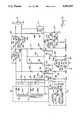
- FIG. 5is a detailed schematic diagram of a circuit for use in the preferred embodiment of the apparatus according to the invention.
- FIG. 6A to FIG. 6Irepresent waveforms associated with the circuit of FIG. 5.
- the inventionis described herein with respect to an implantable defibrillator which is believed to be its primary, most important and most urgent area of application. However, it will be recognized in the art that the invention may be applied to external defibrillators and to cardioverters as well.
- an implantable defibrillator 10is implanted subcutaneously in a patient, generally in an abdominal muscle.
- An epicardial sensing lead 12 including an insulated conductor wireis in electrical continuity with a ventricular sensing electrode 14 used for sensing ventricular electrical activity.
- a pervenous sensing leadmay be threaded through an appropriate vein and positioned in the right ventricle 16 of the heart 18.
- a terminal assembly (not shown) at the proximal end 20 of sensing lead 12is inserted into a first receptacle (not shown) within the neck 22 of implantable defibrillator 10.
- sensing lead 12when inserted in its respective receptacle, is electrically connected to the insulated conductor and to the circuitry of the defibrillator 10.
- This capsulated in case 24is a low impedance battery, using lithium vanadium pentoxide or lithium silver vanadium pentoxide chemistry.
- a terminal assembly (not shown) of a second lead 26is connected to implantable defibrillator 10 via a second receptacle in neck 22 of defibrillator 10.
- the insulated conductor wire of lead 26is tunneled subcutaneously.
- An electrode pad 28 at the distal end of lead 26is sutured onto the epicardial surface of the left ventricle 30 of the heart 18 during a thoracotomy or median sternotomy A subxiphoid approach may also be used.
- a defibrillatory electrode 32which acts as a cathode for the delivery of the first phase of biphasic defibrillation shocks, protrudes slightly from the cardiac surface of electrode pad 28 of lead 26.
- lead 26 with its electrode 32 and lead 33 with its electrode 29are epicardial
- either leadmay be epicardial or pervenous.
- one lead and electrodemay be pervenous, while the other may be a subcutaneous patch.
- the increased efficiency of defibrillation of an asymmetric biphasic truncated exponential pulse in accordance with the inventionwould thus permit the installation of an implantable defibrillator without necessitating opening the chest cavity. This greatly increases the desirability of the apparatus according to the invention by reducing the risk of patient morbidity or mortality as a result of risks associated with a more extensive surgical procedure.
- the circuitry 34 within the titanium case 24is comprised of a fibrillation detector 36 (or a tachycardia detector for purposes of cardioversion) which may include any of several well-known arrhythmia detectors and a countershock or defibrillation circuit 38.
- a fibrillation detector 36or a tachycardia detector for purposes of cardioversion
- the circuitry 34 within the titanium case 24is comprised of a fibrillation detector 36 (or a tachycardia detector for purposes of cardioversion) which may include any of several well-known arrhythmia detectors and a countershock or defibrillation circuit 38.
- Electrical activity generated by the ventricles 16,30 of the heart 18is transmitted by the ventricular sensing electrode 14 to the fibrillation detector 36. If the detected ventricular activity is classified as fibrillation, as indicated by a chaotic, non-rhythmic electrical activity, defibrillator circuit 38 is enabled.
- the pulse forming or defibrillator circuit 38is, in, simplified or conceptual form, comprised of a capacitor 39, a series of switches 40, 42, 44, and 46, which appropriately open and close in response to signals from a timer circuit 49 (as described below, also with reference to FIG. 4), to deliver defibrillation shocks to the heart 18, and optionally, a switch 48 and a resistive load 50.
- an asymmetric biphasic exponential waveform 52as recorded between defibrillatory electrodes 29 and 32 is measured from a baseline 54.
- Waveform 52has a leading edge 56 of amplitude V1.
- the leading edgeis followed by an exponential decay 58 of 2 to 8 milliseconds (for a time which may preferably be equal to approximately 0.7 times the time constant of capacitor 39 and the defibrillation resistance of the heart) to a second voltage level V2, at trailing edge 60, which waveform 52 returns to baseline 54.
- a zero voltage period 62 of 0.1 to 5.0 millisecondsis followed by a polarity reversal.
- the voltage V2is then applied to the heart at leading edge 63 and a second exponential decay 64 occurs, which is preferably of the same duration, as the first decay 58.
- the voltagefalls to a third voltage level V3 at trailing edge 66, from which it returns to baseline 54.
- Asymmetric biphasic exponential waveform 52is generated by utilizing circuit 38 in the following manner: capacitor 39 is charged by an energy source (not shown in FIG. 3) to a voltage V1 of the polarity shown. Switches 40 and 42 are closed by timer circuit 49 placing capacitor 39 in series with the heart 18. Current flows through the heart 18 in the direction of the arrow 68 discharging the capacitor to voltage V2. Switches 44, 46 and 48 are open during this time. Then, capacitor 39 is disconnected from the heart 18 and the voltage level of capacitor 39 is held at V2 when timer circuit 49 causes switches 40 and 42 to open.
- timer circuit 49causes switch 44 and switch 46 to close, thereby discharging capacitor 39 to voltage V3.
- the second phaseis truncated when timer circuit 49 causes switch 44 and switch 46 to open (all others having remained open).
- Optional switch 48may then be closed causing capacitor 39 to discharge into resistive load 50.
- the defibrillatory pulseis actually made up of two pulses of current which travel through the heart first in one direction and then in the opposite direction increasing the probability of depolarizing and then rendering refractory a larger volume of the cardiac muscle fiber.
- the refractorinessmakes it unlikely for fibrillation to continue.
- the capacitoris recharged and an additional pulse or pulses having the waveform illustrated in FIG. 4 may be administered.
- FIG. 5includes a charging circuit 72 of conventional type for charging a single capacitor bank 74, a comparator circuit 77 for providing electrical signals indicative of the voltage to which capacitor bank 74 has been charged and a switching circuit shown generally at 78, which is a practical implementation of the concept of FIG. 3. While timer circuit 49 is not described, the necessary waveforms and their relationships in time are described below with respect to FIG. 6B to FIG. 6G.
- capacitor bank 74When fibrillation is detected by fibrillation detector 36 (FIG. 2) capacitor bank 74 is charged by capacitor charging circuit 72.
- Charging circuit 72may be any of several well-known circuits which have provisions for a "soft start” so that the large current demands placed on the battery at the beginning of the charge cycle are somewhat reduced in magnitude and provisions for low battery voltage detection means for temporarily halting the charge cycle to permit battery recovery should the battery voltage drop to a predetermined low level.
- capacitor bank 74would preferably include only a single capacitor, the limitations in capacitor technology, and in particular the limitations of aluminum electrolytic capacitors are such that the maximum working voltage is not sufficient to withstand the maximum voltage to which the capacitor must be charged.
- capacitor bank 74may be made up of two capacitors 74A and 74B which are connected in series and charged by charging circuit 72. Specifically, capacitor 74A is charged by a secondary winding 75A of a step up transformer 75 through a diode 76A. In a similar manner, capacitor 74B is charged by current from secondary winding 75B of transformer 75 through diode 76B.
- a voltage divider including resistors 80 and 82 and a smoothing capacitor 84provide an output voltage to comparator circuit 77 which is proportional to, but a small fraction of, the voltage across capacitor bank 74.
- Comparator circuit 77includes an integrated circuit comparator 90.
- the positive supply voltage from the battery, appropriately increased in level by, for example, voltage doublingis always supplied to circuit 90.
- the negative supply voltage to comparator 90is connected through a MOSFET 92 which becomes conductive only upon application of an analog power enable signal to the gate thereof. Comparator 90 is thus turned off most of the time for purposes for saving power and turned on only during time periods when a voltage "measurement" must be made.
- a sample-and-hold circuit including a MOSFET 94 and a capacitor 96provides a reference voltage to one input of comparator 90.
- the other input of comparator 90is connected to the junction between resistors 80 and 82.
- defibrillation lead 26acts as a return for electrical conduction to the heart.
- the pacing and/or sensing signals from this leadare conducted through MOSFET 100 for this purpose.
- MOSFET 100must be at least partially switched on at all times except during the charging of capacitor bank 74 at which time MOSFET 100 is switched off to provide protection against accidental discharge.
- MOSFET 100is turned on by a switching circuit including MOSFETS 102 and 104. When the signal S2N (FIG. 6B) is at ground potential MOSFET 104 is off and MOSFET 102 is turned on. Diode 106 becomes conductive thus raising the potential of the gate of MOSFET 100 by conducting current through resistor 108.
- Capacitor 110smoothes the voltage at the gate of MOSFET 100 and prevents transient impulses from turning on MOSFET 100.
- Capacitor 112protects MOSFET 100 against currents due to electrosurgery by providing a bypass between the source and drain thereof.
- MOSFET 100While MOSFET 100 is held on so that its internal resistance is in the order of 20 to 30 ohms for sensing and pacing (when S2N is at logic zero), in order to conduct a defibrillation pulse MOSFET 100 must be put into a very low resistance condition or "turned on hard" so that its internal impedance is of a mere fraction of an ohm. This is accomplished through the action of MOSFETS 114 and 116 as well as capacitor 118. When S2BOOSTN from timer circuit 49 is at a logic high voltage level, MOSFET 114 is turned off and MOSFET 116 is turned on.
- Capacitor 118is charged through diode 106 so that the side facing diode 106 is at a voltage close to that of the positive supply voltage (the doubled battery voltage).
- S2BOOSTNis dropped to ground potential by timer circuit 49. This turns off MOSFET 116 and turns on MOSFET 114. The result is to place capacitor 118 in series with the positive supply voltage so that approximately twice that voltage is applied across the source and drain of MOSFET 104 (off at that time). This results in MOSFET 100 being turned on hard.
- Zener diode 120serves to limit the voltage applied between the source and gate of MOSFET 100 so that it is not damaged.
- MOSFETS 102, 104, 114 and 118may all be on a single type CD4007 chip.
- SCR 122 and SCR 124In order to provide a defibrillation shock to the heart, it also necessary to turn on SCR 122 and SCR 124. This is accomplished when timer circuit 49 provides a pulse S1 (not shown in FIG. 6A to FIG. 6H) to the gate of MOSFET 126 completing a circuit through the primary winding 130A of transformer 130, current limiting resistor 132 and MOSFET 126.
- the surge of current through primary winding 130Ainduces a voltage in a first secondary winding 130B and a second secondary winding 130C of transformer 130. If the polarities of connection of the windings of transformer 130 are as indicated in FIG. 5, SCR 122 and SCR 124 are triggered. False triggering is prevented by capacitor 134 across secondary 130B and capacitor 136 across secondary 130C.
- timer circuit 49causes S2N and S2BOOSTN to return to a logic high state thus turning off MOSFET 100, commutating SCR 122 and SCR 124 (FIG. 6D) and terminating the initial phase of discharge of capacitor bank 74. At this point capacitor bank 74 is electrically disconnected from the heart.
- timer circuit 49does not interact with the circuit of FIG. 5. In other words, there is a delay of 0.1 millisecond to 5 milliseconds during which no current is delivered to the heart 18. After this delay, capacitor bank 74 is reconnected to the heart with its polarity reversed.
- timer circuit 49causes the voltage S5N (FIG. 6E) applied to resistor 140 to go from a positive logic level to zero volts (ground). Since the emitter of transistor 142 is connected to the positive supply voltage, this causes transistor 142 to turn on which in turn causes triggering of SCR 144 by way of current conducted through resistor 146. Before this occurs, the full voltage of capacitor bank 74 appears across SCR 148.
- resistor 150will have a resistance value at least 10 times as great as that of resistor 152.
- the voltageis gradually shifted due to the discharge time of a capacitor 154 through the series combination of resistor 152 and SCR 144.
- a practical time constantmay be on the order of 10 to 50 microseconds.
- This shift in voltageis represented by the change in the voltage at point A (the connection point of SCR 122 and SCR 124) as shown in FIG. 6H.
- Timer circuit 49causes the heart 18 to be connected to capacitor bank 74 by turning on SCR 148 and SCR 156.
- SCR 148is triggered by changing the voltage S4N (FIG. 6F) applied to resistor 158 from a logic high state to a logic zero state (ground), thus turning on transistor 160 (the emitter of which is connected to the positive supply voltage) and triggering SCR 148 due to current conducted through resistor 162.
- the path of current from capacitor bank 74includes SCR 156, a lead connection terminal within neck 22 of defibrillator 10, defibrillation lead 26, the heart 18, defibrillation lead 33, a second lead terminal within neck 22 of defibrillator 10, a diode 174, a resistor 172 (which has a value of no greater than several ohms) and finally SCR 148.
- voltage V2(FIG. 4 and FIG. 6A) is applied to the heart and decays to voltage V3 due to discharge of capacitor bank 74.
- This second phase of the shock applied to the heartis truncated at a time so that its duration is preferably equal to the duration of the first phase (of opposite polarity) applied to the heart.
- a third voltage representative of a desired value of V3may be loaded on to capacitor 96 of comparator circuit 77, and a change in output of comparator 90 used to initiate truncation.
- timer circuit 49again supplies a short pulse to the gate of MOSFET 126, again triggering SCR 122 (as represented by pulse P, FIG. 6D). Capacitor bank 74 is thus discharged through SCR 122, resistor 172 and SCR 148.
- An additional SCR 178, and a resistor 180 having a resistance of, for example, 50 ohms (which is comparable to the defibrillation path resistance of the heart)form a test load for the battery, capacitor charging circuit 72 and capacitor bank 74 and provide a means for dissipating the energy of capacitor bank 74 if charging is performed but no shock is applied to the heart.
- a voltage S6N applied to a resistor 182is changed from a positive logic voltage to ground thus turning on a transistor 184 having an emitter connected to the positive supply voltage and triggering SCR 178 when current is conducted through a resistor 186.
- Capacitor bank 74is placed in series with the heart by turning on MOSFET 100 and then closing SCR 122 and SCR 124 simultaneously at point b.
- Capacitor bank 74is allowed to discharge to voltage V2 during interval c.
- Capacitor bank 74is disconnected from the heart by opening MOSFET 100, SCR 122 and SCR 124 at point d.
- capacitor bank 74is reconnected to the heart with inverted polarity by first closing SCR 144 to slowly shift voltage from SCR 148 to SCR 122 and then by closing SCR 148 and SCR 156 (the latter at point e).
- Voltage V2is applied to the heart and capacitor bank 74 is discharged to voltage V3 during interval f.
- the second phaseis truncated at V3 by closing SCR 122 which shunts charge in capacitor bank 74 away from the heart through the path defined by SCR 122, resistor 172 and SCR 148 during time interval g.
- a major advantage of the circuit of FIG. 5is that no SCR's are exposed to rapid positive voltage changes at any time. Resistor 150, resistor 152, capacitor 154 and SCR 144 preload SCR 122 into its blocking mode prior to application of voltage V2 to the heart. The elimination of rapid positive voltage changes makes possible the use of commonly available and inexpensive switching components.
- the SCRs which conduct defibrillation currentmay all be of type 2N6509, while MOSFET 102 may be a type IRF450. Building a more dependable and less complex energy delivery system by using such proven components is of major importance because in an implantable defibrillator any departure from high reliability would be anathema.
- the circuitcan be used to provide single monophasic pulses or sequential monophasic pulses by modifying the timing of appropriate control signals from timer circuit 49.
- bypass circuitincluding resistor 188 and capacitor 190 may be provided.
Landscapes
- Health & Medical Sciences (AREA)
- Cardiology (AREA)
- Heart & Thoracic Surgery (AREA)
- Engineering & Computer Science (AREA)
- Biomedical Technology (AREA)
- Nuclear Medicine, Radiotherapy & Molecular Imaging (AREA)
- Radiology & Medical Imaging (AREA)
- Life Sciences & Earth Sciences (AREA)
- Animal Behavior & Ethology (AREA)
- General Health & Medical Sciences (AREA)
- Public Health (AREA)
- Veterinary Medicine (AREA)
- Electrotherapy Devices (AREA)
Abstract
Description
Claims (18)
Priority Applications (1)
| Application Number | Priority Date | Filing Date | Title |
|---|---|---|---|
| US07/574,510US5083562A (en) | 1988-01-19 | 1990-08-28 | Method and apparatus for applying asymmetric biphasic truncated exponential countershocks |
Applications Claiming Priority (3)
| Application Number | Priority Date | Filing Date | Title |
|---|---|---|---|
| US14551588A | 1988-01-19 | 1988-01-19 | |
| US39763789A | 1989-08-23 | 1989-08-23 | |
| US07/574,510US5083562A (en) | 1988-01-19 | 1990-08-28 | Method and apparatus for applying asymmetric biphasic truncated exponential countershocks |
Related Parent Applications (1)
| Application Number | Title | Priority Date | Filing Date |
|---|---|---|---|
| US39763789AContinuation | 1988-01-19 | 1989-08-23 |
Publications (1)
| Publication Number | Publication Date |
|---|---|
| US5083562Atrue US5083562A (en) | 1992-01-28 |
Family
ID=27386274
Family Applications (1)
| Application Number | Title | Priority Date | Filing Date |
|---|---|---|---|
| US07/574,510Expired - LifetimeUS5083562A (en) | 1988-01-19 | 1990-08-28 | Method and apparatus for applying asymmetric biphasic truncated exponential countershocks |
Country Status (1)
| Country | Link |
|---|---|
| US (1) | US5083562A (en) |
Cited By (96)
| Publication number | Priority date | Publication date | Assignee | Title |
|---|---|---|---|---|
| US5199429A (en)* | 1991-05-23 | 1993-04-06 | Angemed, Inc. | Implantable defibrillator system employing capacitor switching networks |
| US5215083A (en)* | 1991-10-07 | 1993-06-01 | Telectronics Pacing Systems, Inc. | Apparatus and method for arrhythmia induction in arrhythmia control system |
| US5224476A (en)* | 1992-02-24 | 1993-07-06 | Duke University | Method and apparatus for controlling fibrillation or tachycardia |
| US5306291A (en)* | 1992-02-26 | 1994-04-26 | Angeion Corporation | Optimal energy steering for an implantable defibrillator |
| US5312444A (en)* | 1992-06-22 | 1994-05-17 | Incontrol, Inc. | Crosspoint switch with improved discharge control for use in an implantable defibrillator |
| US5372606A (en)* | 1993-10-07 | 1994-12-13 | Cardiac Pacemakers, Inc. | Method and apparatus for generating adaptive n-phasic defibrillation waveforms |
| US5376103A (en)* | 1992-03-19 | 1994-12-27 | Angeion Corporation | Electrode system for implantable defibrillator |
| US5385575A (en)* | 1992-03-24 | 1995-01-31 | Angeion Corporation | Implantable cardioverter defibrillator having variable output capacitance |
| WO1995003087A1 (en)* | 1993-07-26 | 1995-02-02 | Cardiac Pacemakers, Inc. | Method and apparatus for defibrillation using a multiphasic truncated exponential waveform |
| US5411528A (en)* | 1992-11-19 | 1995-05-02 | Pacesetter, Inc. | Electrically programmable polarity connector for an implantable body tissue stimulator |
| US5411526A (en)* | 1992-03-24 | 1995-05-02 | Angeion Corporation | Improved implantable defibrillator system for producing true-voltage-pulse waveforms |
| US5433729A (en)* | 1991-04-12 | 1995-07-18 | Incontrol, Inc. | Atrial defibrillator, lead systems, and method |
| US5439481A (en)* | 1992-02-26 | 1995-08-08 | Angeion Corporation | Semi-automatic atrial and ventricular cardioverter defibrillator |
| US5507781A (en)* | 1991-05-23 | 1996-04-16 | Angeion Corporation | Implantable defibrillator system with capacitor switching circuitry |
| US5591209A (en)* | 1994-05-19 | 1997-01-07 | Angeion Corporation | Implantable defibrillator system for generating an active biphasic waveform |
| US5593427A (en)* | 1993-08-06 | 1997-01-14 | Heartstream, Inc. | Electrotherapy method |
| US5601608A (en)* | 1995-02-02 | 1997-02-11 | Pacesetter, Inc. | Methods and apparatus for applying charge-balanced antiarrhythmia shocks |
| US5601609A (en)* | 1993-09-15 | 1997-02-11 | Pacesetter, Inc. | Implantable cardiac stimulating device and method for administering synchronized cardioversion shock therapy to provide preemptive depolarization |
| US5607454A (en)* | 1993-08-06 | 1997-03-04 | Heartstream, Inc. | Electrotherapy method and apparatus |
| US5620471A (en)* | 1995-06-16 | 1997-04-15 | Pacesetter, Inc. | System and method for discriminating between atrial and ventricular arrhythmias and for applying cardiac therapy therefor |
| US5713926A (en)* | 1990-04-25 | 1998-02-03 | Cardiac Pacemakers, Inc. | Implantable intravenous cardiac stimulation system with pulse generator housing serving as optional additional electrode |
| US5722995A (en)* | 1995-06-08 | 1998-03-03 | Survivalink Corporation | External defibrillator for producing and testing biphasic waveforms |
| US5733310A (en)* | 1996-12-18 | 1998-03-31 | Zmd Corporation | Electrotherapy circuit and method for producing therapeutic discharge waveform immediately following sensing pulse |
| US5769872A (en)* | 1996-12-18 | 1998-06-23 | Zmd Corporation | Electrotherapy circuit and method for shaping current waveforms |
| US5797968A (en)* | 1996-12-18 | 1998-08-25 | Zmd Corporation | Electrotherapy circuit for producing current waveform with sawtooth ripple |
| US5800463A (en)* | 1996-12-18 | 1998-09-01 | Zmd Corporation | Electrotherapy circuit having controlled peak current |
| US5800462A (en)* | 1996-12-18 | 1998-09-01 | Zmd Corporation | Electrotherapy circuit for producing therapeutic discharge waveform based on high-current sensing pulse |
| WO1998039060A1 (en) | 1997-03-05 | 1998-09-11 | Physio-Control Manufacturing Corporation | H-bridge circuit for generating a high-energy biphasic waveform in an external defibrillator |
| US5833712A (en)* | 1991-05-23 | 1998-11-10 | Angeion Corporation | Implantable defibrillator system for generating a biphasic waveform |
| US5869970A (en)* | 1995-10-31 | 1999-02-09 | Cardiac Pacemakers, Inc. | Power management system for an implantable device |
| US5873893A (en)* | 1997-03-05 | 1999-02-23 | Physio-Control Corporation | Method and apparatus for verifying the integrity of an output circuit before and during application of a defibrillation pulse |
| US5904706A (en)* | 1996-12-18 | 1999-05-18 | Zmd Corporation | Method and apparatus for producing electrotherapy current waveform with ripple |
| US5913887A (en)* | 1996-03-01 | 1999-06-22 | Cardiac Pacemakers, Inc. | Device for the transvenous cardioversion of atrial fibrillation or atrial flutter including three coil electrodes |
| US5916243A (en)* | 1992-11-24 | 1999-06-29 | Cardiac Pacemakers, Inc. | Implantable conformal coil patch electrode with multiple conductive elements for cardioversion and defibrillation |
| US5968080A (en)* | 1996-07-01 | 1999-10-19 | Survivalink Corporation | Method for determining the second phase of external defibrillator devices |
| WO2000021610A1 (en)* | 1998-10-13 | 2000-04-20 | Medtronic Physio-Control Manufacturing Corp. | Semiconductor assisted relay in a biphasic defibrillator |
| US6085119A (en)* | 1998-07-22 | 2000-07-04 | Cardiac Pacemakers, Inc. | Single pass endocardial lead for multi-site atrial pacing |
| US6096063A (en)* | 1996-12-18 | 2000-08-01 | Zmd Corporation | Electrotherapy circuit having controlled current discharge based on patient-dependent electrical parameter |
| US6104954A (en)* | 1997-06-30 | 2000-08-15 | Blunsden; Christopher K. | High frequency lead testing apparatus in an implantable defibrillator |
| US6104953A (en)* | 1999-01-28 | 2000-08-15 | Heartstream, Inc. | Method and apparatus for delivering defibrillation and pacing energy from a single power source |
| US6152954A (en)* | 1998-07-22 | 2000-11-28 | Cardiac Pacemakers, Inc. | Single pass lead having retractable, actively attached electrode for pacing and sensing |
| US6167309A (en)* | 1997-09-15 | 2000-12-26 | Cardiac Pacemakers, Inc. | Method for monitoring end of life for battery |
| US6208896B1 (en) | 1998-11-13 | 2001-03-27 | Agilent Technologies, Inc. | Method and apparatus for providing variable defibrillation waveforms using switch-mode amplification |
| US6212434B1 (en) | 1998-07-22 | 2001-04-03 | Cardiac Pacemakers, Inc. | Single pass lead system |
| US6230054B1 (en) | 1999-04-23 | 2001-05-08 | Agilent Technologies, Inc. | Apparatus for controlling delivery of defibrillation energy |
| US6233483B1 (en) | 1997-05-14 | 2001-05-15 | Pacesetter, Inc. | System and method for generating a high efficiency biphasic defibrillation waveform for use in an implantable cardioverter/defibrillator (ICD). |
| US6263239B1 (en) | 1996-07-01 | 2001-07-17 | Survivalink Corporation | Method and apparatus for determining the second phase of defibrillator devices |
| US6321122B1 (en) | 1998-07-22 | 2001-11-20 | Cardiac Pacemakers, Inc. | Single pass defibrillation/pacing lead with passively attached electrode for pacing and sensing |
| US6405081B1 (en) | 1999-04-22 | 2002-06-11 | Koninklijke Philips Electronics N.V. | Damped biphasic energy delivery circuit for a defibrillator |
| US6411846B1 (en) | 1999-08-26 | 2002-06-25 | Survivalink Corporation | Method and apparatus for delivering a biphasic defibrillation pulse with variable energy |
| US20020120302A1 (en)* | 1999-04-30 | 2002-08-29 | Cardiac Pacemakers, Inc. | Implantable cardiac stimulating device with optimized demand |
| US6463334B1 (en) | 1998-11-02 | 2002-10-08 | Cardiac Pacemakers, Inc. | Extendable and retractable lead |
| US6477413B1 (en) | 1997-03-05 | 2002-11-05 | Medtronic Physio-Control Manufacturing Corp. | H-bridge circuit for generating a high-energy biphasic waveform in an external defibrillator |
| US6484056B2 (en) | 1997-05-14 | 2002-11-19 | Pacesetter, Inc. | System and method of generating a high efficiency biphasic defibrillation waveform for use in an implantable cardioverter/defibrillator (ICD) |
| US6501994B1 (en) | 1997-12-24 | 2002-12-31 | Cardiac Pacemakers, Inc. | High impedance electrode tip |
| WO2003022358A1 (en)* | 2001-09-06 | 2003-03-20 | Medtronic,Inc. | A system for reducing noise in an implantable medical device |
| US6539255B1 (en) | 1998-07-16 | 2003-03-25 | Cardiac Science, Inc. | Full-tilt exponential defibrillation waveform |
| US20030069625A1 (en)* | 1998-07-22 | 2003-04-10 | Ley Gregory R. | Lead with terminal connector assembly |
| US20030171779A1 (en)* | 2002-03-11 | 2003-09-11 | Medtronic Physio-Control Manufacturing Corp. | Method and apparatus for self-test of defibrillation and pacing circuits including a patient isolation switch |
| US20030171780A1 (en)* | 2002-03-11 | 2003-09-11 | Medtronic Physio-Control Manufacturing Corp. | Method and apparatus for self-test of defibrillation and pacing circuits including a patient isolation switch |
| US20030176897A1 (en)* | 2001-04-10 | 2003-09-18 | Cardiac Pacemakers, Inc. | System and method for measuring battery current |
| US6631293B2 (en) | 1997-09-15 | 2003-10-07 | Cardiac Pacemakers, Inc. | Method for monitoring end of life for battery |
| US20040044371A1 (en)* | 2002-09-04 | 2004-03-04 | Medtronic Physio-Control Manufacturing Corp. | Defibrillator with H-bridge output circuit referenced to common ground |
| US6714818B1 (en) | 1997-05-14 | 2004-03-30 | Pacesetter, Inc. | System and method of generating an optimal three-step defibrillation waveform for use in an implantable cardioverter/defibrillator (ICD) |
| US20040068301A1 (en)* | 1997-03-05 | 2004-04-08 | Medtronic Physio-Control Manufacturing Corp. | H-bridge circuit for generating a high-energy biphasic waveform in an external defibrillator using single SCR and IGBT switches in an integrated package |
| US20040127946A1 (en)* | 2002-12-30 | 2004-07-01 | Wagner Darrell O. | Method and apparatus for atrial tachyarrhythmia cardioversion |
| US20040193222A1 (en)* | 2003-03-24 | 2004-09-30 | Sullivan Joseph L. | Balanced charge waveform for transcutaneous pacing |
| US20050007073A1 (en)* | 2003-07-11 | 2005-01-13 | James Kristofer J. | Indicator of remaining energy in storage cell of implantable medical device |
| US20050020871A1 (en)* | 2003-07-21 | 2005-01-27 | Piergiorgio Tozzi | Artificial contractile tissue |
| US20050088145A1 (en)* | 2003-10-23 | 2005-04-28 | Robert Loch | Battery charge indicator such as for an implantable medical device |
| US20050131464A1 (en)* | 2000-11-22 | 2005-06-16 | Heinrich Stephen D. | Apparatus for detecting and treating ventricular arrhythmia |
| US6968230B2 (en) | 2002-06-26 | 2005-11-22 | Medtronic Physio-Control Manufacturing Corp | H-bridge circuit for generating a high-energy biphasic and external pacing waveform in an external defibrillator |
| US20050277994A1 (en)* | 2004-06-09 | 2005-12-15 | Mcnamee Paul | Apparatus and method for estimating battery condition in implantable cardiac devices |
| US6980856B2 (en) | 1998-10-13 | 2005-12-27 | Physio-Control Manufacturing Corporation | Circuit for performing external pacing and biphasic defibrillation |
| US20060116633A1 (en)* | 2002-07-16 | 2006-06-01 | Yehoshua Shachar | System and method for a magnetic catheter tip |
| WO2006067158A1 (en)* | 2004-12-23 | 2006-06-29 | Schiller Medical Sas | Defibrillator having a secure discharging circuit comprising an h-bridge |
| US20060235479A1 (en)* | 2000-09-18 | 2006-10-19 | Cameron Health, Inc. | Monophasic waveform for anti-bradycardia pacing for a subcutaneous implantable cardioverter-defibrillator |
| US20070016006A1 (en)* | 2005-05-27 | 2007-01-18 | Yehoshua Shachar | Apparatus and method for shaped magnetic field control for catheter, guidance, control, and imaging |
| US20070055314A1 (en)* | 2000-09-18 | 2007-03-08 | Cameron Health, Inc. | Post-shock treatment in a subcutaneous device |
| US20070197891A1 (en)* | 2006-02-23 | 2007-08-23 | Yehoshua Shachar | Apparatus for magnetically deployable catheter with MOSFET sensor and method for mapping and ablation |
| US20080027313A1 (en)* | 2003-10-20 | 2008-01-31 | Magnetecs, Inc. | System and method for radar-assisted catheter guidance and control |
| US20080297287A1 (en)* | 2007-05-30 | 2008-12-04 | Magnetecs, Inc. | Magnetic linear actuator for deployable catheter tools |
| US20100130854A1 (en)* | 2008-11-25 | 2010-05-27 | Magnetecs, Inc. | System and method for a catheter impedance seeking device |
| WO2010146492A1 (en) | 2009-06-19 | 2010-12-23 | Koninklijke Philips Electronics, N.V. | Biphasic defibrillator waveform with adjustable second phase tilt |
| US20130282079A1 (en)* | 2012-04-24 | 2013-10-24 | Medtronic, Inc. | Charge-balancing during electrical stimulation |
| US20140081114A1 (en)* | 2012-09-17 | 2014-03-20 | Magnetecs Inc. | Method and apparatus for measuring biopotential and mapping ephaptic coupling employing a catheter with mosfet sensor array |
| US8706217B2 (en) | 2000-09-18 | 2014-04-22 | Cameron Health | Cardioverter-defibrillator having a focused shocking area and orientation thereof |
| US8718760B2 (en) | 2000-09-18 | 2014-05-06 | Cameron Health Inc. | Subcutaneous implantable cardioverter-defibrillator placement methods |
| US8831720B2 (en) | 2000-09-18 | 2014-09-09 | Cameron Health, Inc. | Method of implanting and using a subcutaneous defibrillator |
| US9126055B2 (en) | 2012-04-20 | 2015-09-08 | Cardiac Science Corporation | AED faster time to shock method and device |
| US9138589B2 (en) | 2001-11-21 | 2015-09-22 | Cameron Health, Inc. | Apparatus and method for identifying atrial arrhythmia by far-field sensing |
| US9655539B2 (en) | 2009-11-09 | 2017-05-23 | Magnetecs, Inc. | System and method for targeting catheter electrodes |
| US10953234B2 (en) | 2015-08-26 | 2021-03-23 | Element Science, Inc. | Wearable devices |
| US11185709B2 (en) | 2014-02-24 | 2021-11-30 | Element Science, Inc. | External defibrillator |
| US11253715B2 (en) | 2018-10-10 | 2022-02-22 | Element Science, Inc. | Wearable medical device with disposable and reusable components |
| US11369795B2 (en) | 2018-04-27 | 2022-06-28 | Medtronic, Inc. | Method and apparatus for charge balancing during delivery of electrical stimulation |
Citations (12)
| Publication number | Priority date | Publication date | Assignee | Title |
|---|---|---|---|---|
| US3224447A (en)* | 1962-06-25 | 1965-12-21 | Mine Safety Appliances Co | Electrodes for ventricular defibrillator |
| US3614955A (en)* | 1970-02-09 | 1971-10-26 | Medtronic Inc | Standby defibrillator and method of operation |
| US4120305A (en)* | 1976-09-10 | 1978-10-17 | Vrl Growth Associates, Inc. | System for administering an electric shock |
| US4498478A (en)* | 1982-09-13 | 1985-02-12 | Medtronic, Inc. | Apparatus for reducing polarization potentials in a pacemaker |
| US4576170A (en)* | 1980-07-09 | 1986-03-18 | Micro-Circuits Company | Heart monitor and defibrillator device |
| US4637397A (en)* | 1985-05-30 | 1987-01-20 | Case Western Reserve University | Triphasic wave defibrillation |
| EP0281219A1 (en)* | 1987-01-14 | 1988-09-07 | Medtronic, Inc. | Cardiac defibrillator |
| US4800883A (en)* | 1986-04-02 | 1989-01-31 | Intermedics, Inc. | Apparatus for generating multiphasic defibrillation pulse waveform |
| US4821723A (en)* | 1987-02-27 | 1989-04-18 | Intermedics Inc. | Biphasic waveforms for defibrillation |
| US4830006A (en)* | 1986-06-17 | 1989-05-16 | Intermedics, Inc. | Implantable cardiac stimulator for detection and treatment of ventricular arrhythmias |
| US4850357A (en)* | 1988-01-12 | 1989-07-25 | Cardiac Pacemakers, Inc. | Biphasic pulse generator for an implantable defibrillator |
| US4953551A (en)* | 1987-01-14 | 1990-09-04 | Medtronic, Inc. | Method of defibrillating a heart |
- 1990
- 1990-08-28USUS07/574,510patent/US5083562A/ennot_activeExpired - Lifetime
Patent Citations (13)
| Publication number | Priority date | Publication date | Assignee | Title |
|---|---|---|---|---|
| US3224447A (en)* | 1962-06-25 | 1965-12-21 | Mine Safety Appliances Co | Electrodes for ventricular defibrillator |
| US3614955A (en)* | 1970-02-09 | 1971-10-26 | Medtronic Inc | Standby defibrillator and method of operation |
| US4120305A (en)* | 1976-09-10 | 1978-10-17 | Vrl Growth Associates, Inc. | System for administering an electric shock |
| US4576170A (en)* | 1980-07-09 | 1986-03-18 | Micro-Circuits Company | Heart monitor and defibrillator device |
| US4498478A (en)* | 1982-09-13 | 1985-02-12 | Medtronic, Inc. | Apparatus for reducing polarization potentials in a pacemaker |
| US4637397A (en)* | 1985-05-30 | 1987-01-20 | Case Western Reserve University | Triphasic wave defibrillation |
| US4800883A (en)* | 1986-04-02 | 1989-01-31 | Intermedics, Inc. | Apparatus for generating multiphasic defibrillation pulse waveform |
| US4830006A (en)* | 1986-06-17 | 1989-05-16 | Intermedics, Inc. | Implantable cardiac stimulator for detection and treatment of ventricular arrhythmias |
| US4830006B1 (en)* | 1986-06-17 | 1997-10-28 | Intermedics Inc | Implantable cardiac stimulator for detection and treatment of ventricular arrhythmias |
| EP0281219A1 (en)* | 1987-01-14 | 1988-09-07 | Medtronic, Inc. | Cardiac defibrillator |
| US4953551A (en)* | 1987-01-14 | 1990-09-04 | Medtronic, Inc. | Method of defibrillating a heart |
| US4821723A (en)* | 1987-02-27 | 1989-04-18 | Intermedics Inc. | Biphasic waveforms for defibrillation |
| US4850357A (en)* | 1988-01-12 | 1989-07-25 | Cardiac Pacemakers, Inc. | Biphasic pulse generator for an implantable defibrillator |
Non-Patent Citations (38)
| Title |
|---|
| B. D. Lindsay et al., "Prospective Evaluation of a Sequential Pacing and High-Energy Bidirectional Shock Algorithm for Transvenous Cardioversion in Patients with Ventricular Tachycardia," Therapy and Prevention, vol. 76, No. 3 (Sep., 1987). |
| B. D. Lindsay et al., Prospective Evaluation of a Sequential Pacing and High Energy Bidirectional Shock Algorithm for Transvenous Cardioversion in Patients with Ventricular Tachycardia, Therapy and Prevention, vol. 76, No. 3 (Sep., 1987).* |
| J. L. Jones & R. E. Jones, "Defibrillator Waveshape Optimization," Devices & Tech. Meeting, NIH, 1982; p. 175. |
| J. L. Jones & R. E. Jones, "Improved Defibrillator Waveform Safety Factor with Biphasic Waveforms," The American Journal of Physiology, 7/83; 245:1; pp. H60-H65. |
| J. L. Jones & R. E. Jones, Defibrillator Waveshape Optimization, Devices & Tech. Meeting, NIH, 1982; p. 175.* |
| J. L. Jones & R. E. Jones, Improved Defibrillator Waveform Safety Factor with Biphasic Waveforms, The American Journal of Physiology, 7/83; 245:1; pp. H60 H65.* |
| Langer et al., "Considerations in the Development of the Automatic Implantable Defibrillator," Medical Instrumentation: vol. 10, No. 3; May-Jun. 1976; pp. 163-167. |
| Langer et al., Considerations in the Development of the Automatic Implantable Defibrillator, Medical Instrumentation: vol. 10, No. 3; May Jun. 1976; pp. 163 167.* |
| Mirowski et al., "Clinical Treatment of Life-Threatening Ventricular Tachyarrhythmias with the Automatic Implantable Defibrillator," Amer. Heart Journal; 8/81, pp. 265-270. |
| Mirowski et al., "Termination of Malignant Ventricular Arrhythmias with an Implanted Automatic Defibrillator in Human Beings," New Eng. Journal of Med.; 8/7/80; pp. 322-324. |
| Mirowski et al., Clinical Treatment of Life Threatening Ventricular Tachyarrhythmias with the Automatic Implantable Defibrillator, Amer. Heart Journal; 8/81, pp. 265 270.* |
| Mirowski et al., Termination of Malignant Ventricular Arrhythmias with an Implanted Automatic Defibrillator in Human Beings, New Eng. Journal of Med.; 8/7/80; pp. 322 324.* |
| R. A. Winkle, "The Implantable Defibrillator in Ventricular Arrhythmias," Hospital Practice, Mar. 1983, pp. 149-165. |
| R. A. Winkle, The Implantable Defibrillator in Ventricular Arrhythmias, Hospital Practice, Mar. 1983, pp. 149 165.* |
| S. Saksena et al., "A Prospective Evaluation of Single and Dual Current Pathways for Transvenous Cardioversion in Rapid Ventricular Tachycardia," PACE, vol. 10, pp. 1130-1141 (Sep.-Oct., 1987). |
| S. Saksena et al., "Developments for Future Implantable Cardioverters and Defibrillators," PACE, vol. 10, pp. 1342-1358 (Nov.-Dec., 1987). |
| S. Saksena et al., A Prospective Evaluation of Single and Dual Current Pathways for Transvenous Cardioversion in Rapid Ventricular Tachycardia, PACE, vol. 10, pp. 1130 1141 (Sep. Oct., 1987).* |
| S. Saksena et al., Developments for Future Implantable Cardioverters and Defibrillators, PACE, vol. 10, pp. 1342 1358 (Nov. Dec., 1987).* |
| Schuder et al., "Defibrillation of 100 kg Calves with Asymmetrical, Bidirectional, Rectangular Pulses," Cardiovascular Research; 1984:18; pp. 419-426. |
| Schuder et al., "Development of Automatic Implanted Defibrillator," Devices & Tech. Meeting, NIH; p. 206 (1981). |
| Schuder et al., "One-Cycle Bidirectional Rectangular Wave Shocks for Open Chest Defibrillation in the Calf," Abs. Amer. Soc. Artificial Internal Organs; 9:16. |
| Schuder et al., "Transthoracic Ventricular Defibrillation in the 100 kg Calf with Symmetrical One-Cycle Bidirectional Rectangular Wave Stimuli," IEEE Transactions on Biomedical Engineering, vol. BME-30, No. 7; Jul. 1983; pp. 415-422. |
| Schuder et al., "Ultrahigh-Energy Hydrogen Thyratron/SCR Bidirectional Waveform Defibrillator," Medical & Biological Engineering & Computing, Jul. 1982, pp. 419-424. |
| Schuder et al., "Waveform Dependency in Defibrillating 100 kg Calves," Devices & Tech. Meeting, NIH, 1982; p. 174. |
| Schuder et al., Defibrillation of 100 kg Calves with Asymmetrical, Bidirectional, Rectangular Pulses, Cardiovascular Research; 1984:18; pp. 419 426.* |
| Schuder et al., Development of Automatic Implanted Defibrillator, Devices & Tech. Meeting, NIH; p. 206 (1981).* |
| Schuder et al., One Cycle Bidirectional Rectangular Wave Shocks for Open Chest Defibrillation in the Calf, Abs. Amer. Soc. Artificial Internal Organs; 9:16.* |
| Schuder et al., Transthoracic Ventricular Defibrillation in the 100 kg Calf with Symmetrical One Cycle Bidirectional Rectangular Wave Stimuli, IEEE Transactions on Biomedical Engineering, vol. BME 30, No. 7; Jul. 1983; pp. 415 422.* |
| Schuder et al., Ultrahigh Energy Hydrogen Thyratron/SCR Bidirectional Waveform Defibrillator, Medical & Biological Engineering & Computing, Jul. 1982, pp. 419 424.* |
| Schuder et al., Waveform Dependency in Defibrillating 100 kg Calves, Devices & Tech. Meeting, NIH, 1982; p. 174.* |
| Tang et al., "Strength Duration Curve for Ventricular Defibrillation Using Biphasic Waveforms," The North Amer. Society of Pacing and Electrophysiology; May 2, 1987; p. 49. |
| Tang et al., "Ventricular Defibrillation Using Biphasic Waveforms of Different Phasic Duration," PACE: vol. 10; Mar.-Apr. 1987. |
| Tang et al., Strength Duration Curve for Ventricular Defibrillation Using Biphasic Waveforms, The North Amer. Society of Pacing and Electrophysiology; May 2, 1987; p. 49.* |
| Tang et al., Ventricular Defibrillation Using Biphasic Waveforms of Different Phasic Duration, PACE: vol. 10; Mar. Apr. 1987.* |
| W. B. Kouwenhoven, Annals of Internal Medicine, vol. 71, No. 3, pp. 449 458 (Sep., 1969).* |
| W. B. Kouwenhoven, Annals of Internal Medicine, vol. 71, No. 3, pp. 449-458 (Sep., 1969). |
| Winkle et al., "Improved Low Energy Defibrillation Efficacy in Man Using a Biphasic Truncated Exponential Waveform," JACC; vol. 9, No. 2; Feb. 1987; p. 142A. |
| Winkle et al., Improved Low Energy Defibrillation Efficacy in Man Using a Biphasic Truncated Exponential Waveform, JACC; vol. 9, No. 2; Feb. 1987; p. 142A.* |
Cited By (194)
| Publication number | Priority date | Publication date | Assignee | Title |
|---|---|---|---|---|
| US5916238A (en)* | 1990-04-25 | 1999-06-29 | Cardiac Pacemakers, Inc. | Implantable intravenous cardiac stimulation system with pulse generator housing serving as optional additional electrode |
| US20050119707A1 (en)* | 1990-04-25 | 2005-06-02 | Cardiac Pacemakers, Inc. | Subcutaneous cardiac rhythm management |
| US6280462B1 (en) | 1990-04-25 | 2001-08-28 | Cardiac Pacemakers, Inc. | Implantable intravenous cardiac stimulation system with pulse generator housing serving as optional additional electrode |
| US6999814B2 (en) | 1990-04-25 | 2006-02-14 | Cardiac Pacemakers, Inc. | Implantable intravenous cardiac stimulation system with pulse generator housing serving as optional additional electrode |
| US6157860A (en)* | 1990-04-25 | 2000-12-05 | Cardiac Pacemakers, Inc. | Implantable intravenous cardiac stimulation system with pulse generator housing serving as optional additional electrode |
| US7522959B2 (en) | 1990-04-25 | 2009-04-21 | Cardiac Pacemakers, Inc. | Subcutaneous cardiac rhythm management |
| US5713926A (en)* | 1990-04-25 | 1998-02-03 | Cardiac Pacemakers, Inc. | Implantable intravenous cardiac stimulation system with pulse generator housing serving as optional additional electrode |
| US5433729A (en)* | 1991-04-12 | 1995-07-18 | Incontrol, Inc. | Atrial defibrillator, lead systems, and method |
| US5833712A (en)* | 1991-05-23 | 1998-11-10 | Angeion Corporation | Implantable defibrillator system for generating a biphasic waveform |
| US5199429A (en)* | 1991-05-23 | 1993-04-06 | Angemed, Inc. | Implantable defibrillator system employing capacitor switching networks |
| US5507781A (en)* | 1991-05-23 | 1996-04-16 | Angeion Corporation | Implantable defibrillator system with capacitor switching circuitry |
| US5215083A (en)* | 1991-10-07 | 1993-06-01 | Telectronics Pacing Systems, Inc. | Apparatus and method for arrhythmia induction in arrhythmia control system |
| US5224476A (en)* | 1992-02-24 | 1993-07-06 | Duke University | Method and apparatus for controlling fibrillation or tachycardia |
| US5413591A (en)* | 1992-02-26 | 1995-05-09 | Angeion Corporation | Current truncated waveform defibrillator |
| US5735878A (en)* | 1992-02-26 | 1998-04-07 | Angeion Corporation | Implantable defibrillator having multiple pathways |
| US5439481A (en)* | 1992-02-26 | 1995-08-08 | Angeion Corporation | Semi-automatic atrial and ventricular cardioverter defibrillator |
| US5306291A (en)* | 1992-02-26 | 1994-04-26 | Angeion Corporation | Optimal energy steering for an implantable defibrillator |
| US5514160A (en)* | 1992-02-26 | 1996-05-07 | Angeion Corporation | Implantable defibrillator for producing a rectangular-shaped defibrillation waveform |
| US5376103A (en)* | 1992-03-19 | 1994-12-27 | Angeion Corporation | Electrode system for implantable defibrillator |
| US5385575A (en)* | 1992-03-24 | 1995-01-31 | Angeion Corporation | Implantable cardioverter defibrillator having variable output capacitance |
| US5411526A (en)* | 1992-03-24 | 1995-05-02 | Angeion Corporation | Improved implantable defibrillator system for producing true-voltage-pulse waveforms |
| US5312444A (en)* | 1992-06-22 | 1994-05-17 | Incontrol, Inc. | Crosspoint switch with improved discharge control for use in an implantable defibrillator |
| US5411528A (en)* | 1992-11-19 | 1995-05-02 | Pacesetter, Inc. | Electrically programmable polarity connector for an implantable body tissue stimulator |
| US6152955A (en)* | 1992-11-24 | 2000-11-28 | Cardiac Pacemakers, Inc. | Implantable conformal coil patch electrode with multiple conductive elements for cardioversion and defibrillation |
| US6038483A (en)* | 1992-11-24 | 2000-03-14 | Cardiac Pacemakers, Inc. | Implantable conformal coil patch electrode with multiple conductive elements for cardioversion and defibrillation |
| US6032079A (en)* | 1992-11-24 | 2000-02-29 | Cardiac Pacemakers, Inc. | Implantable conformal coil electrode with multiple conductive elements for cardioversion and defibrillation |
| US6026332A (en)* | 1992-11-24 | 2000-02-15 | Cardiac Pacemakers, Inc. | Implantable conformal coil patch electrode with multiple conductive elements for cardioversion and defibrillation |
| US5916243A (en)* | 1992-11-24 | 1999-06-29 | Cardiac Pacemakers, Inc. | Implantable conformal coil patch electrode with multiple conductive elements for cardioversion and defibrillation |
| US5468254A (en)* | 1993-07-26 | 1995-11-21 | Cardiac Pacemakers, Inc. | Method and apparatus for defibrillation using a multiphasic truncated exponential waveform |
| WO1995003087A1 (en)* | 1993-07-26 | 1995-02-02 | Cardiac Pacemakers, Inc. | Method and apparatus for defibrillation using a multiphasic truncated exponential waveform |
| EP0997162A1 (en)* | 1993-08-06 | 2000-05-03 | Heartstream, Inc. | Electrotherapy apparatus |
| US5607454A (en)* | 1993-08-06 | 1997-03-04 | Heartstream, Inc. | Electrotherapy method and apparatus |
| US5620470A (en)* | 1993-08-06 | 1997-04-15 | Heartstream, Inc. | Electrotherapy method |
| US5776166A (en)* | 1993-08-06 | 1998-07-07 | Heartstream, Inc. | Method for applying a multiphasic waveform |
| US6047212A (en)* | 1993-08-06 | 2000-04-04 | Heartstream, Inc. | External defibrillator capable of delivering patient impedance compensated biphasic waveforms |
| US5593427A (en)* | 1993-08-06 | 1997-01-14 | Heartstream, Inc. | Electrotherapy method |
| EP0712321A4 (en)* | 1993-08-06 | 1997-12-17 | Heartstream Inc | Electrotherapy method and apparatus |
| US5803927A (en)* | 1993-08-06 | 1998-09-08 | Heartstream, Inc. | Electrotherapy method and apparatus for external defibrillation |
| US5601612A (en)* | 1993-08-06 | 1997-02-11 | Heartstream, Inc. | Method for applying a multiphasic waveform |
| US5749904A (en)* | 1993-08-06 | 1998-05-12 | Heartstream, Inc. | Electrotherapy method utilizing patient dependent electrical parameters |
| US5749905A (en)* | 1993-08-06 | 1998-05-12 | Heartstream, Inc. | Electrotherapy method utilizing patient dependent electrical parameters |
| US5836978A (en)* | 1993-08-06 | 1998-11-17 | Heartstream, Inc. | Electrotherapy method for producing a multiphasic discharge based upon a patient-dependent electrical parameter and time |
| US5601609A (en)* | 1993-09-15 | 1997-02-11 | Pacesetter, Inc. | Implantable cardiac stimulating device and method for administering synchronized cardioversion shock therapy to provide preemptive depolarization |
| US5372606A (en)* | 1993-10-07 | 1994-12-13 | Cardiac Pacemakers, Inc. | Method and apparatus for generating adaptive n-phasic defibrillation waveforms |
| US5591209A (en)* | 1994-05-19 | 1997-01-07 | Angeion Corporation | Implantable defibrillator system for generating an active biphasic waveform |
| US5601608A (en)* | 1995-02-02 | 1997-02-11 | Pacesetter, Inc. | Methods and apparatus for applying charge-balanced antiarrhythmia shocks |
| US5722995A (en)* | 1995-06-08 | 1998-03-03 | Survivalink Corporation | External defibrillator for producing and testing biphasic waveforms |
| US5620471A (en)* | 1995-06-16 | 1997-04-15 | Pacesetter, Inc. | System and method for discriminating between atrial and ventricular arrhythmias and for applying cardiac therapy therefor |
| US5869970A (en)* | 1995-10-31 | 1999-02-09 | Cardiac Pacemakers, Inc. | Power management system for an implantable device |
| US5959371A (en)* | 1995-10-31 | 1999-09-28 | Cardiac Pacemakers, Inc. | Power management system for an implantable device |
| US6426628B1 (en) | 1995-10-31 | 2002-07-30 | Cardiac Pacemakers, Inc. | Power management system for an implantable device |
| US20040193240A1 (en)* | 1996-03-01 | 2004-09-30 | Cardiac Pacemakers, Inc. | Device for the transvenous cardioversion of atrial fibrillation or atrial flutter |
| US6438416B1 (en) | 1996-03-01 | 2002-08-20 | Cardiac Pacemakers, Inc. | Device for the transvenous cardioversion of atrial fibrillation or atrial flutter including three coil electrodes |
| US5913887A (en)* | 1996-03-01 | 1999-06-22 | Cardiac Pacemakers, Inc. | Device for the transvenous cardioversion of atrial fibrillation or atrial flutter including three coil electrodes |
| US6041256A (en)* | 1996-03-01 | 2000-03-21 | Cardiac Pacemakers, Inc. | Device for the transvenous cardioversion of atrial fibrillation or atrial flutter |
| US6741894B2 (en) | 1996-03-01 | 2004-05-25 | Cardiac Pacemakers, Inc. | Device for the transvenous cardioversion of atrial fibrillation or atrial flutter |
| US7366574B2 (en) | 1996-03-01 | 2008-04-29 | Cardiac Pacemakers, Inc. | Device for the transvenous cardioversion of atrial fibrillation or atrial flutter |
| US6263239B1 (en) | 1996-07-01 | 2001-07-17 | Survivalink Corporation | Method and apparatus for determining the second phase of defibrillator devices |
| US5968080A (en)* | 1996-07-01 | 1999-10-19 | Survivalink Corporation | Method for determining the second phase of external defibrillator devices |
| US7463923B2 (en) | 1996-07-01 | 2008-12-09 | Cardiac Science Corporation | Method and apparatus for delivering a biphasic defibrillation pulse with variable energy |
| US20040172072A1 (en)* | 1996-07-01 | 2004-09-02 | Cardiac Science Inc. | Method and apparatus for delivering a biphasic defibrillation pulse with variable energy |
| US5904706A (en)* | 1996-12-18 | 1999-05-18 | Zmd Corporation | Method and apparatus for producing electrotherapy current waveform with ripple |
| US5797968A (en)* | 1996-12-18 | 1998-08-25 | Zmd Corporation | Electrotherapy circuit for producing current waveform with sawtooth ripple |
| US5733310A (en)* | 1996-12-18 | 1998-03-31 | Zmd Corporation | Electrotherapy circuit and method for producing therapeutic discharge waveform immediately following sensing pulse |
| US5800462A (en)* | 1996-12-18 | 1998-09-01 | Zmd Corporation | Electrotherapy circuit for producing therapeutic discharge waveform based on high-current sensing pulse |
| US5800463A (en)* | 1996-12-18 | 1998-09-01 | Zmd Corporation | Electrotherapy circuit having controlled peak current |
| US5769872A (en)* | 1996-12-18 | 1998-06-23 | Zmd Corporation | Electrotherapy circuit and method for shaping current waveforms |
| US6096063A (en)* | 1996-12-18 | 2000-08-01 | Zmd Corporation | Electrotherapy circuit having controlled current discharge based on patient-dependent electrical parameter |
| EP1452204A2 (en) | 1997-03-05 | 2004-09-01 | Physio-Control Manufacturing Corporation | H-bridge circuit for generating a high-energy biphasic waveform in an external defibrillator |
| US5873893A (en)* | 1997-03-05 | 1999-02-23 | Physio-Control Corporation | Method and apparatus for verifying the integrity of an output circuit before and during application of a defibrillation pulse |
| US20040068301A1 (en)* | 1997-03-05 | 2004-04-08 | Medtronic Physio-Control Manufacturing Corp. | H-bridge circuit for generating a high-energy biphasic waveform in an external defibrillator using single SCR and IGBT switches in an integrated package |
| US6041254A (en)* | 1997-03-05 | 2000-03-21 | Physio-Control Manufacturing Corporation | H-bridge circuit for generating a high-energy biphasic waveform in an external defibrillator and further including a protective component that has both inductive and resistive properties |
| US6963773B2 (en) | 1997-03-05 | 2005-11-08 | Medtronic Physio-Control Manufacturing Corp. | H-bridge circuit for generating a high-energy biphasic waveform in an external defibrillator using single SCR and IGBT switches in an integrated package |
| US5824017A (en)* | 1997-03-05 | 1998-10-20 | Physio-Control Corporation | H-bridge circuit for generating a high-energy biphasic waveform in an external defibrillator |
| US6477413B1 (en) | 1997-03-05 | 2002-11-05 | Medtronic Physio-Control Manufacturing Corp. | H-bridge circuit for generating a high-energy biphasic waveform in an external defibrillator |
| WO1998039060A1 (en) | 1997-03-05 | 1998-09-11 | Physio-Control Manufacturing Corporation | H-bridge circuit for generating a high-energy biphasic waveform in an external defibrillator |
| US6714818B1 (en) | 1997-05-14 | 2004-03-30 | Pacesetter, Inc. | System and method of generating an optimal three-step defibrillation waveform for use in an implantable cardioverter/defibrillator (ICD) |
| US6763266B1 (en) | 1997-05-14 | 2004-07-13 | Pacesetter, Inc. | System and method of generating a low-pain multi-step defibrillation waveform for use in an implantable cardioverter/defibrillator (ICD) |
| US6745073B1 (en) | 1997-05-14 | 2004-06-01 | Pacesetter, Inc. | System and method of generating a low-pain multi-step defibrillation waveform for use in an implantable cardioverter/defibrillator (ICD) |
| US6954669B1 (en) | 1997-05-14 | 2005-10-11 | Pacesetter, Inc. | System and method of generating an optimal three-step defibrillation waveform for use in an implantable cardioverter/defibrillator (ICD) |
| US6772007B1 (en) | 1997-05-14 | 2004-08-03 | Pacesetter, Inc. | System and method of generating a low-pain multi-step defibrillation waveform for use in an implantable cardioverter/defibrillator (ICD) |
| US6484056B2 (en) | 1997-05-14 | 2002-11-19 | Pacesetter, Inc. | System and method of generating a high efficiency biphasic defibrillation waveform for use in an implantable cardioverter/defibrillator (ICD) |
| US6233483B1 (en) | 1997-05-14 | 2001-05-15 | Pacesetter, Inc. | System and method for generating a high efficiency biphasic defibrillation waveform for use in an implantable cardioverter/defibrillator (ICD). |
| US6104954A (en)* | 1997-06-30 | 2000-08-15 | Blunsden; Christopher K. | High frequency lead testing apparatus in an implantable defibrillator |
| US7515962B2 (en) | 1997-09-15 | 2009-04-07 | Cardiac Pacemakers, Inc. | Method for monitoring end of life for battery |
| US7251527B2 (en) | 1997-09-15 | 2007-07-31 | Cardiac Pacemakers, Inc. | Method for monitoring end of life for battery |
| US20070265672A1 (en)* | 1997-09-15 | 2007-11-15 | Cardiac Pacemakers, Inc. | Method for monitoring end of life for battery |
| US7580749B2 (en) | 1997-09-15 | 2009-08-25 | Cardiac Pacemakers, Inc. | Method for monitoring end of life for battery |
| US6631293B2 (en) | 1997-09-15 | 2003-10-07 | Cardiac Pacemakers, Inc. | Method for monitoring end of life for battery |
| US6654640B2 (en) | 1997-09-15 | 2003-11-25 | Cardiac Pacemakers, Inc. | Method for monitoring end of life for battery |
| US20040024426A1 (en)* | 1997-09-15 | 2004-02-05 | Cardiac Pacemakers, Inc. | Method for monitoring end of life for battery |
| US6167309A (en)* | 1997-09-15 | 2000-12-26 | Cardiac Pacemakers, Inc. | Method for monitoring end of life for battery |
| US20040073264A1 (en)* | 1997-09-15 | 2004-04-15 | Cardiac Pacemakers, Inc. | Method for monitoring end of life for battery |
| US6501994B1 (en) | 1997-12-24 | 2002-12-31 | Cardiac Pacemakers, Inc. | High impedance electrode tip |
| US20040133259A1 (en)* | 1997-12-24 | 2004-07-08 | Cardiac Pacemakers, Inc. | High impedance electrode tip |
| US6539255B1 (en) | 1998-07-16 | 2003-03-25 | Cardiac Science, Inc. | Full-tilt exponential defibrillation waveform |
| US6085119A (en)* | 1998-07-22 | 2000-07-04 | Cardiac Pacemakers, Inc. | Single pass endocardial lead for multi-site atrial pacing |
| US8209035B2 (en) | 1998-07-22 | 2012-06-26 | Cardiac Pacemakers, Inc. | Extendable and retractable lead having a snap-fit terminal connector |
| US6152954A (en)* | 1998-07-22 | 2000-11-28 | Cardiac Pacemakers, Inc. | Single pass lead having retractable, actively attached electrode for pacing and sensing |
| US7392095B2 (en) | 1998-07-22 | 2008-06-24 | Cardiac Pacemakers, Inc. | Extendable and retractable lead having a snap-fit terminal connector |
| US7774934B2 (en) | 1998-07-22 | 2010-08-17 | Cardiac Pacemakers, Inc. | Method for making a terminal connector |
| US20080262587A1 (en)* | 1998-07-22 | 2008-10-23 | Cardiac Pacemakers, Inc | Extendable and retractable lead having a snap-fit terminal connector |
| US20030069625A1 (en)* | 1998-07-22 | 2003-04-10 | Ley Gregory R. | Lead with terminal connector assembly |
| US6505082B1 (en) | 1998-07-22 | 2003-01-07 | Cardiac Pacemakers, Inc. | Single pass lead system |
| US6345204B1 (en) | 1998-07-22 | 2002-02-05 | Cardiac Pacemakers, Inc. | Single pass lead having retractable, actively attached electrode for pacing and sensing |
| US6212434B1 (en) | 1998-07-22 | 2001-04-03 | Cardiac Pacemakers, Inc. | Single pass lead system |
| US6915169B2 (en) | 1998-07-22 | 2005-07-05 | Cardiac Pacemakers, Inc. | Extendable and retractable lead having a snap-fit terminal connector |
| US6983185B2 (en) | 1998-07-22 | 2006-01-03 | Cardiac Pacemakers, Inc. | Lead with terminal connector assembly |
| US20060089698A1 (en)* | 1998-07-22 | 2006-04-27 | Cardiac Pacemakers, Inc. | Lead with terminal connector assembly |
| US6321122B1 (en) | 1998-07-22 | 2001-11-20 | Cardiac Pacemakers, Inc. | Single pass defibrillation/pacing lead with passively attached electrode for pacing and sensing |
| US8285398B2 (en) | 1998-07-22 | 2012-10-09 | Cardiac Pacemakers, Inc. | Lead with terminal connector assembly |
| WO2000021610A1 (en)* | 1998-10-13 | 2000-04-20 | Medtronic Physio-Control Manufacturing Corp. | Semiconductor assisted relay in a biphasic defibrillator |
| US6173204B1 (en) | 1998-10-13 | 2001-01-09 | Physio-Control Manufacturing Corporation | Semiconductor assisted relay in a biphasic defibrillator |
| US6980856B2 (en) | 1998-10-13 | 2005-12-27 | Physio-Control Manufacturing Corporation | Circuit for performing external pacing and biphasic defibrillation |
| US6463334B1 (en) | 1998-11-02 | 2002-10-08 | Cardiac Pacemakers, Inc. | Extendable and retractable lead |
| US6208896B1 (en) | 1998-11-13 | 2001-03-27 | Agilent Technologies, Inc. | Method and apparatus for providing variable defibrillation waveforms using switch-mode amplification |
| US6104953A (en)* | 1999-01-28 | 2000-08-15 | Heartstream, Inc. | Method and apparatus for delivering defibrillation and pacing energy from a single power source |
| US7079894B2 (en) | 1999-04-22 | 2006-07-18 | Koninklijke Philips Electronics, N.V. | Damped biphasic energy delivery circuit for a defibrillator |
| US20050101999A1 (en)* | 1999-04-22 | 2005-05-12 | Lyster Thomas D. | Damped biphasic energy delivery circuit for a defibrillator |
| US6405081B1 (en) | 1999-04-22 | 2002-06-11 | Koninklijke Philips Electronics N.V. | Damped biphasic energy delivery circuit for a defibrillator |
| US6230054B1 (en) | 1999-04-23 | 2001-05-08 | Agilent Technologies, Inc. | Apparatus for controlling delivery of defibrillation energy |
| US6892096B2 (en) | 1999-04-30 | 2005-05-10 | Cardiac Pacemakers, Inc. | Implantable cardiac stimulating device with optimized demand |
| US20020120302A1 (en)* | 1999-04-30 | 2002-08-29 | Cardiac Pacemakers, Inc. | Implantable cardiac stimulating device with optimized demand |
| US6411846B1 (en) | 1999-08-26 | 2002-06-25 | Survivalink Corporation | Method and apparatus for delivering a biphasic defibrillation pulse with variable energy |
| US8706217B2 (en) | 2000-09-18 | 2014-04-22 | Cameron Health | Cardioverter-defibrillator having a focused shocking area and orientation thereof |
| US8718760B2 (en) | 2000-09-18 | 2014-05-06 | Cameron Health Inc. | Subcutaneous implantable cardioverter-defibrillator placement methods |
| US9144683B2 (en) | 2000-09-18 | 2015-09-29 | Cameron Health, Inc. | Post-shock treatment in a subcutaneous device |
| US20070055314A1 (en)* | 2000-09-18 | 2007-03-08 | Cameron Health, Inc. | Post-shock treatment in a subcutaneous device |
| US20060235479A1 (en)* | 2000-09-18 | 2006-10-19 | Cameron Health, Inc. | Monophasic waveform for anti-bradycardia pacing for a subcutaneous implantable cardioverter-defibrillator |
| US8831720B2 (en) | 2000-09-18 | 2014-09-09 | Cameron Health, Inc. | Method of implanting and using a subcutaneous defibrillator |
| US7627375B2 (en) | 2000-09-18 | 2009-12-01 | Cameron Health, Inc. | Implantable cardiac stimulus methods |
| US20050143776A1 (en)* | 2000-11-22 | 2005-06-30 | Cardiac Pacemakers, Inc. | Apparatus for detecting and treating ventricular arrhythmia |
| US20050131464A1 (en)* | 2000-11-22 | 2005-06-16 | Heinrich Stephen D. | Apparatus for detecting and treating ventricular arrhythmia |
| US9022962B2 (en)* | 2000-11-22 | 2015-05-05 | Boston Scientific Scimed, Inc. | Apparatus for detecting and treating ventricular arrhythmia |
| US20080140139A1 (en)* | 2000-11-22 | 2008-06-12 | Heinrich Stephen D | Apparatus for detecting and treating ventricular arrhythmia |
| US20050143782A1 (en)* | 2001-04-10 | 2005-06-30 | Cardiac Pacemakers, Inc. | System and method for measuring battery current |
| US6885894B2 (en) | 2001-04-10 | 2005-04-26 | Cardiac Pacemakers, Inc. | System and method for measuring battery current |
| US20030176897A1 (en)* | 2001-04-10 | 2003-09-18 | Cardiac Pacemakers, Inc. | System and method for measuring battery current |
| US7191005B2 (en) | 2001-04-10 | 2007-03-13 | Cardiac Pacemakers, Inc. | System and method for measuring battery current |
| US6754527B2 (en) | 2001-09-06 | 2004-06-22 | Medtronic, Inc. | System and method for reducing noise in an implantable medical device |
| WO2003022358A1 (en)* | 2001-09-06 | 2003-03-20 | Medtronic,Inc. | A system for reducing noise in an implantable medical device |
| US9522283B2 (en) | 2001-11-21 | 2016-12-20 | Cameron Health Inc. | Apparatus and method for identifying atrial arrhythmia by far-field sensing |
| US9993653B2 (en) | 2001-11-21 | 2018-06-12 | Cameron Health, Inc. | Apparatus and method for identifying atrial arrhythmia by far-field sensing |
| US9138589B2 (en) | 2001-11-21 | 2015-09-22 | Cameron Health, Inc. | Apparatus and method for identifying atrial arrhythmia by far-field sensing |
| US7096062B2 (en) | 2002-03-11 | 2006-08-22 | Medtronic Physio-Control Manufacturing Corp. | Method for self-test of defibrillation and pacing circuits including a patient isolation switch |
| US20030171780A1 (en)* | 2002-03-11 | 2003-09-11 | Medtronic Physio-Control Manufacturing Corp. | Method and apparatus for self-test of defibrillation and pacing circuits including a patient isolation switch |
| US20030171779A1 (en)* | 2002-03-11 | 2003-09-11 | Medtronic Physio-Control Manufacturing Corp. | Method and apparatus for self-test of defibrillation and pacing circuits including a patient isolation switch |
| US6965796B2 (en) | 2002-03-11 | 2005-11-15 | Medtronic Physio-Control Manufacturing Corp. | Method and apparatus for self-test of defibrillation and pacing circuits including a patient isolation switch |
| US6968230B2 (en) | 2002-06-26 | 2005-11-22 | Medtronic Physio-Control Manufacturing Corp | H-bridge circuit for generating a high-energy biphasic and external pacing waveform in an external defibrillator |
| US7873401B2 (en) | 2002-07-16 | 2011-01-18 | Magnetecs, Inc. | System and method for a magnetic catheter tip |
| US20060116633A1 (en)* | 2002-07-16 | 2006-06-01 | Yehoshua Shachar | System and method for a magnetic catheter tip |
| US20040044371A1 (en)* | 2002-09-04 | 2004-03-04 | Medtronic Physio-Control Manufacturing Corp. | Defibrillator with H-bridge output circuit referenced to common ground |
| US7110811B2 (en) | 2002-12-30 | 2006-09-19 | Cardiac Pacemakers, Inc. | Method and apparatus for atrial tachyarrhythmia cardioversion |
| US20040127946A1 (en)* | 2002-12-30 | 2004-07-01 | Wagner Darrell O. | Method and apparatus for atrial tachyarrhythmia cardioversion |
| US8027721B2 (en)* | 2003-03-24 | 2011-09-27 | Physio-Control, Inc. | Balanced charge waveform for transcutaneous pacing |
| US9566440B2 (en) | 2003-03-24 | 2017-02-14 | Physio-Control, Inc. | Balanced charge waveform for transcutaneous pacing |
| US20040193222A1 (en)* | 2003-03-24 | 2004-09-30 | Sullivan Joseph L. | Balanced charge waveform for transcutaneous pacing |
| US7239146B2 (en) | 2003-07-11 | 2007-07-03 | Cardiac Pacemakers, Inc. | Indicator of remaining energy in storage cell of implantable medical device |
| US20050007073A1 (en)* | 2003-07-11 | 2005-01-13 | James Kristofer J. | Indicator of remaining energy in storage cell of implantable medical device |
| US20050020871A1 (en)* | 2003-07-21 | 2005-01-27 | Piergiorgio Tozzi | Artificial contractile tissue |
| US7873402B2 (en) | 2003-10-20 | 2011-01-18 | Magnetecs, Inc. | System and method for radar-assisted catheter guidance and control |
| US20080027313A1 (en)* | 2003-10-20 | 2008-01-31 | Magnetecs, Inc. | System and method for radar-assisted catheter guidance and control |
| US20050088145A1 (en)* | 2003-10-23 | 2005-04-28 | Robert Loch | Battery charge indicator such as for an implantable medical device |
| US6940255B2 (en) | 2003-10-23 | 2005-09-06 | Cardiac Pacemakers, Inc. | Battery charge indicator such as for an implantable medical device |
| US20050277994A1 (en)* | 2004-06-09 | 2005-12-15 | Mcnamee Paul | Apparatus and method for estimating battery condition in implantable cardiac devices |
| US20110106190A1 (en)* | 2004-12-23 | 2011-05-05 | Schiller Medical S.A.S. | Defibrillator Having a Secure Discharging Circuit Comprising an H-Bridge |
| RU2365389C2 (en)* | 2004-12-23 | 2009-08-27 | Шиллер Медикаль Сас | Defibrillator with safe discharge contour, containing h-shaped bridge electric scheme |
| WO2006067158A1 (en)* | 2004-12-23 | 2006-06-29 | Schiller Medical Sas | Defibrillator having a secure discharging circuit comprising an h-bridge |
| US8027714B2 (en) | 2005-05-27 | 2011-09-27 | Magnetecs, Inc. | Apparatus and method for shaped magnetic field control for catheter, guidance, control, and imaging |
| US20070016006A1 (en)* | 2005-05-27 | 2007-01-18 | Yehoshua Shachar | Apparatus and method for shaped magnetic field control for catheter, guidance, control, and imaging |
| US20070197891A1 (en)* | 2006-02-23 | 2007-08-23 | Yehoshua Shachar | Apparatus for magnetically deployable catheter with MOSFET sensor and method for mapping and ablation |
| US20090248014A1 (en)* | 2006-02-23 | 2009-10-01 | Magnetecs, Inc. | Apparatus for magnetically deployable catheter with mosfet sensor and method for mapping and ablation |
| US7869854B2 (en) | 2006-02-23 | 2011-01-11 | Magnetecs, Inc. | Apparatus for magnetically deployable catheter with MOSFET sensor and method for mapping and ablation |
| US20080297287A1 (en)* | 2007-05-30 | 2008-12-04 | Magnetecs, Inc. | Magnetic linear actuator for deployable catheter tools |
| US20100130854A1 (en)* | 2008-11-25 | 2010-05-27 | Magnetecs, Inc. | System and method for a catheter impedance seeking device |
| US8457714B2 (en) | 2008-11-25 | 2013-06-04 | Magnetecs, Inc. | System and method for a catheter impedance seeking device |
| US10028721B2 (en) | 2009-06-19 | 2018-07-24 | Koninklijke Philips N.V. | Biphasic defibrillator waveform with adjustable second phase tilt |
| WO2010146492A1 (en) | 2009-06-19 | 2010-12-23 | Koninklijke Philips Electronics, N.V. | Biphasic defibrillator waveform with adjustable second phase tilt |
| US9655539B2 (en) | 2009-11-09 | 2017-05-23 | Magnetecs, Inc. | System and method for targeting catheter electrodes |
| US9126055B2 (en) | 2012-04-20 | 2015-09-08 | Cardiac Science Corporation | AED faster time to shock method and device |
| US9295850B2 (en)* | 2012-04-24 | 2016-03-29 | Medtronic, Inc. | Charge-balancing during electrical stimulation |
| US20130282079A1 (en)* | 2012-04-24 | 2013-10-24 | Medtronic, Inc. | Charge-balancing during electrical stimulation |
| US9220425B2 (en)* | 2012-09-17 | 2015-12-29 | Magnetecs Corp. | Method and apparatus for measuring biopotential and mapping ephaptic coupling employing a catheter with MOSFET sensor array |
| US20140081114A1 (en)* | 2012-09-17 | 2014-03-20 | Magnetecs Inc. | Method and apparatus for measuring biopotential and mapping ephaptic coupling employing a catheter with mosfet sensor array |
| US11185709B2 (en) | 2014-02-24 | 2021-11-30 | Element Science, Inc. | External defibrillator |
| US11975209B2 (en) | 2014-02-24 | 2024-05-07 | Element Science, Inc. | External defibrillator |
| US12427329B2 (en) | 2014-02-24 | 2025-09-30 | Element Science, Inc. | External defibrillator |
| US10953234B2 (en) | 2015-08-26 | 2021-03-23 | Element Science, Inc. | Wearable devices |
| US11701521B2 (en) | 2015-08-26 | 2023-07-18 | Element Science, Inc. | Wearable devices |
| US12350508B2 (en) | 2015-08-26 | 2025-07-08 | Element Science, Inc. | Wearable devices |
| US11369795B2 (en) | 2018-04-27 | 2022-06-28 | Medtronic, Inc. | Method and apparatus for charge balancing during delivery of electrical stimulation |
| US12415078B2 (en) | 2018-04-27 | 2025-09-16 | Medtronic, Inc. | Method and apparatus for charge balancing during delivery of electrical stimulation |
| US11253715B2 (en) | 2018-10-10 | 2022-02-22 | Element Science, Inc. | Wearable medical device with disposable and reusable components |
| US12186573B2 (en) | 2018-10-10 | 2025-01-07 | Element Science, Inc. | Wearable medical device with disposable and reusable components |
Similar Documents
| Publication | Publication Date | Title |
|---|---|---|
| US5083562A (en) | Method and apparatus for applying asymmetric biphasic truncated exponential countershocks | |
| EP0326290B1 (en) | Method and apparatus for applying asymmetric biphasic truncated exponential countershocks | |
| US6865417B2 (en) | H-bridge with sensing circuit | |
| US5251624A (en) | Pulse generator for use in an implantable atrial defibrillator | |
| US7389139B2 (en) | Simplified defibrillator output circuit | |
| US5413591A (en) | Current truncated waveform defibrillator | |
| US4693253A (en) | Automatic implantable defibrillator and pacer | |
| US6047212A (en) | External defibrillator capable of delivering patient impedance compensated biphasic waveforms | |
| US5634938A (en) | Defibrillator waveform generator for generating waveform of long duration | |
| US6405081B1 (en) | Damped biphasic energy delivery circuit for a defibrillator | |
| US4403614A (en) | Implantable cardioverter | |
| US6778860B2 (en) | Switched capacitor defibrillation circuit | |
| US5484452A (en) | Current leakage prevention mechanism for use in a defibrillator circuit | |
| US6873874B2 (en) | Method and apparatus for cardiac shock therapy | |
| US5360435A (en) | Multiple pulse cardioversion or defibrillation | |
| US6438420B1 (en) | High voltage switch isolation for implantable cardioverters/defibrillators | |
| Gould et al. | Pacemaker failure following external defibrillation | |
| US5772689A (en) | Implantable cardioverter-defibrillator with apical shock delivery | |
| Natale et al. | Relative efficacy of different tilts with biphasic defibrillation in humans | |
| US5733309A (en) | Method and apparatus for capacitive switching output for implantable cardioverter defibrillator | |
| EP0023134B1 (en) | Implantable cardioverter | |
| US20030088277A1 (en) | Switched resistor defibrillation circuit | |
| CA1262563A (en) | Protection circuit for implantable cardioverter | |
| WO2001026731A1 (en) | Combined defibrillator and pacemaker |
Legal Events
| Date | Code | Title | Description |
|---|---|---|---|
| STCF | Information on status: patent grant | Free format text:PATENTED CASE | |
| AS | Assignment | Owner name:TELECTRONICS PACING SYSTEMS, INC., COLORADO Free format text:ASSIGNMENT OF ASSIGNORS INTEREST.;ASSIGNOR:TELECTRONICS, N.V.;REEL/FRAME:006050/0345 Effective date:19920317 | |
| CC | Certificate of correction | ||
| FEPP | Fee payment procedure | Free format text:PAYOR NUMBER ASSIGNED (ORIGINAL EVENT CODE: ASPN); ENTITY STATUS OF PATENT OWNER: LARGE ENTITY | |
| FPAY | Fee payment | Year of fee payment:4 | |
| AS | Assignment | Owner name:PACESETTER, INC., CALIFORNIA Free format text:ASSIGNMENT OF ASSIGNORS INTEREST;ASSIGNOR:TELECTRONICS PACING SYSTEMS;REEL/FRAME:008454/0461 Effective date:19961129 | |
| FEPP | Fee payment procedure | Free format text:PAYOR NUMBER ASSIGNED (ORIGINAL EVENT CODE: ASPN); ENTITY STATUS OF PATENT OWNER: LARGE ENTITY Free format text:PAYER NUMBER DE-ASSIGNED (ORIGINAL EVENT CODE: RMPN); ENTITY STATUS OF PATENT OWNER: LARGE ENTITY | |
| FPAY | Fee payment | Year of fee payment:8 | |
| FPAY | Fee payment | Year of fee payment:12 |