US5083218A - Hand-held image reading apparatus - Google Patents
Hand-held image reading apparatusDownload PDFInfo
- Publication number
- US5083218A US5083218AUS07/477,232US47723290AUS5083218AUS 5083218 AUS5083218 AUS 5083218AUS 47723290 AUS47723290 AUS 47723290AUS 5083218 AUS5083218 AUS 5083218A
- Authority
- US
- United States
- Prior art keywords
- image data
- memory means
- image
- respect
- row
- Prior art date
- Legal status (The legal status is an assumption and is not a legal conclusion. Google has not performed a legal analysis and makes no representation as to the accuracy of the status listed.)
- Expired - Lifetime
Links
- 238000000605extractionMethods0.000claimsdescription58
- 238000000034methodMethods0.000claimsdescription12
- 230000004044responseEffects0.000claimsdescription9
- 238000001514detection methodMethods0.000claimsdescription6
- 210000004027cellAnatomy0.000claims4
- 210000000352storage cellAnatomy0.000claims2
- 238000007639printingMethods0.000abstractdescription23
- 239000000284extractSubstances0.000abstractdescription2
- 238000005070samplingMethods0.000description20
- 230000001360synchronised effectEffects0.000description2
- 238000007651thermal printingMethods0.000description2
- 230000007423decreaseEffects0.000description1
- 230000003247decreasing effectEffects0.000description1
- 230000000994depressogenic effectEffects0.000description1
- 238000010586diagramMethods0.000description1
Images


Classifications
- H—ELECTRICITY
- H04—ELECTRIC COMMUNICATION TECHNIQUE
- H04N—PICTORIAL COMMUNICATION, e.g. TELEVISION
- H04N1/00—Scanning, transmission or reproduction of documents or the like, e.g. facsimile transmission; Details thereof
- H04N1/04—Scanning arrangements, i.e. arrangements for the displacement of active reading or reproducing elements relative to the original or reproducing medium, or vice versa
- H04N1/047—Detection, control or error compensation of scanning velocity or position
- H04N1/0476—Indicating the scanning velocity
- H—ELECTRICITY
- H04—ELECTRIC COMMUNICATION TECHNIQUE
- H04N—PICTORIAL COMMUNICATION, e.g. TELEVISION
- H04N1/00—Scanning, transmission or reproduction of documents or the like, e.g. facsimile transmission; Details thereof
- H04N1/04—Scanning arrangements, i.e. arrangements for the displacement of active reading or reproducing elements relative to the original or reproducing medium, or vice versa
- H04N1/10—Scanning arrangements, i.e. arrangements for the displacement of active reading or reproducing elements relative to the original or reproducing medium, or vice versa using flat picture-bearing surfaces
- H04N1/107—Scanning arrangements, i.e. arrangements for the displacement of active reading or reproducing elements relative to the original or reproducing medium, or vice versa using flat picture-bearing surfaces with manual scanning
- H04N1/1077—Arrangements for facilitating movement over the scanned medium, e.g. disposition of rollers
- H—ELECTRICITY
- H04—ELECTRIC COMMUNICATION TECHNIQUE
- H04N—PICTORIAL COMMUNICATION, e.g. TELEVISION
- H04N1/00—Scanning, transmission or reproduction of documents or the like, e.g. facsimile transmission; Details thereof
- H04N1/04—Scanning arrangements, i.e. arrangements for the displacement of active reading or reproducing elements relative to the original or reproducing medium, or vice versa
- H04N1/0461—Scanning arrangements, i.e. arrangements for the displacement of active reading or reproducing elements relative to the original or reproducing medium, or vice versa part of the apparatus being used in common for reading and reproducing
- H—ELECTRICITY
- H04—ELECTRIC COMMUNICATION TECHNIQUE
- H04N—PICTORIAL COMMUNICATION, e.g. TELEVISION
- H04N2201/00—Indexing scheme relating to scanning, transmission or reproduction of documents or the like, and to details thereof
- H04N2201/04—Scanning arrangements
- H04N2201/047—Detection, control or error compensation of scanning velocity or position
- H04N2201/04701—Detection of scanning velocity or position
- H04N2201/0471—Detection of scanning velocity or position using dedicated detectors
- H—ELECTRICITY
- H04—ELECTRIC COMMUNICATION TECHNIQUE
- H04N—PICTORIAL COMMUNICATION, e.g. TELEVISION
- H04N2201/00—Indexing scheme relating to scanning, transmission or reproduction of documents or the like, and to details thereof
- H04N2201/04—Scanning arrangements
- H04N2201/047—Detection, control or error compensation of scanning velocity or position
- H04N2201/04701—Detection of scanning velocity or position
- H04N2201/04715—Detection of scanning velocity or position by detecting marks or the like, e.g. slits
- H04N2201/04724—Detection of scanning velocity or position by detecting marks or the like, e.g. slits on a separate encoder wheel
- H—ELECTRICITY
- H04—ELECTRIC COMMUNICATION TECHNIQUE
- H04N—PICTORIAL COMMUNICATION, e.g. TELEVISION
- H04N2201/00—Indexing scheme relating to scanning, transmission or reproduction of documents or the like, and to details thereof
- H04N2201/04—Scanning arrangements
- H04N2201/047—Detection, control or error compensation of scanning velocity or position
- H04N2201/04701—Detection of scanning velocity or position
- H04N2201/04734—Detecting at frequent intervals, e.g. once per line for sub-scan control
Definitions
- the present inventionrelates to a hand-held image reading apparatus for reading image information from a surface as it moves over the surface, and to a method of operating the apparatus.
- hand-held image reading apparatusessuch as hand-held copiers, hand-held image scanners, and the like, have recently been put into practical use. These apparatuses read a predetermined width of image information from a surface, as they move over the surface. Therefore, they can read the part of an image corresponding to the distance they have moved. Some of these apparatuses are capable of changing the width of the reading area.
- the present inventionhas been made in an attempt to solve the above-described problem of the conventional hand-held image reading apparatuses.
- the objectis to provide a hand-held image reading apparatus which can read only a required part of an image, and a method of operating it.
- the present inventionprovides a hand-held image reading apparatus comprising inputting means for inputting image data in response to a predetermined surface area containing image information memory means for storing the image data inputted by said inputting means extracting means for extracting a set of image data forming one line which exists in the center of image data stored in said memory means and outputting means for outputting the image data detected by said image data detecting means.
- the above-described arrangementprovides a particular advantage in that image data corresponding to only that part of an image required to be read can be precisely obtained, even if that part comprises only one line of a document with narrow line spacing between the line and adjacent lines and thus even if the not required part of the image as well as the required part of the image are stored in the memory means.
- FIG. 1is a perspective view of a hand-held manually sweepable copier according to a preferred embodiment of the invention
- FIG. 2is a schematic block diagram of the internal arrangement of the hand-held manually sweepable copier shown in FIG. 1;
- FIG. 3is a view showing a state in which image information is read by the hand-held manually sweepable copier shown in FIG. 1;
- FIG. 4is a view showing a state in which image data is stored in the image data memory shown in FIG. 2 and a state in which a sampling area is determined by the control unit and the black data detecting unit shown in FIG. 2;
- FIG. 5is a view showing the distribution of black data counted by the black data detecting unit shown in FIG. 2;
- FIG. 6is a view showing a state in which extraction points are determined by the extraction point judging unit and the arithmetic unit shown in FIG. 2;
- FIG. 7is a flow chart for explaining an image data extracting process of the hand-held manually sweepable copier shown in FIG. 1;
- FIG. 8is a view showing a state in which an extraction point is determined in another way by the control unit and the black data detecting unit shown in FIG. 2.
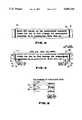
- FIG. 1shows a perspective view of a hand-held manually sweepable copier according to an embodiment of the present invention.
- the copier 10comprises a rectangular housing 11 which is small enough to be held by hand; a reading section 12, provided at one end of the housing 11, for optically reading image information from a surface A; a printing section 13, provided at the other end of the housing 11, for printing the image information read by the reading section 12; rubber rollers 14 and 15, mounted in the housing 11 near the reading section 12 and the printing section 13, respectively, so that they protrude from respective ends of the housing 11; a mode switch 16, mounted on the side surface of the housing 11, for switching between a power source (OFF), a read mode (INPUT) and a print mode (PRINT); and an operation key 17 mounted on the front surface of the housing 11 for starting a read or print operation.
- OFFpower source
- INPUTread mode
- PRINTprint mode
- FIG. 2shows an arrangement of electronic circuits of the copier 10.
- the reading section 12comprises an image sensor 20, an LED array 21, an LED driver 22 and a reading encoder 23.
- the image sensor 20is a 64-dot line-type CCD (Couple Charged Device) with a width of 8 mm and a resolution of 8 dots/mm.
- the longitudinal axis of the image sensor 20is orthogonal to the direction in which the housing 11 is moved across the surface A.
- FIG. 3shows the surface A of a paper which characters are printed and frames F1 and F2 are provided.
- the LED array 21comprises a plurality of LEDs and its longitudinal axis is parallel to that of image sensor 20.
- the LED driver 22drives the LED array 21 so that it illuminates the surface A.
- the reading encoder 23has an encoder disk 24 which has a plurality of slits 25 formed radially at regular intervals, a detector 26 comprising an LED (not shown) and a photosensor (not shown) arranged adjacent to each other at opposing positions with the disk 24 disposed between the LED and the photosensor.
- the disk 24is coupled to one of the rollers 14 and is thus rotated by it.
- the detector 26is situated so that light emitted from the LED is incident upon its photosensor through the slits 25 of the disk 24.
- the detector 26When the disk 24 is rotated by moving the housing 11 such that the rollers 14 are put into contact with the surface A, the light emitted from the LED within the detector 26 is interrupted by the disk 24 at a rate corresponding to the moving speed of the housing 11. Therefore, the detector 26 generates a detecting signal representing the distance through which the housing 11 has been moved.
- the detecting signal generated by the detector 26is outputted to a control unit 27 every time the housing 11 is moved through a predetermined distance
- the image sensor 20generates image signals corresponding to the image information on the surface A illuminated by the LED array 21, and outputs them to an image signal processing unit 28 on the basis of a control signal outputted from the control unit 27.
- This control signalis based upon the detecting signal outputted from the encoder 23.
- the image signal processing unit 28converts the image signals outputted from the image sensor 20 into binary signals (black and white) and outputs the binary signals to control unit 27 in 8 bit parallel as image data.
- the image data outputted from the processing unit 28is stored in an image data memory unit 29 via the control unit 27.
- a rectangular thin linedesignates that area of the surface A which corresponds to a memory area of the image data memory unit 29 shown in FIG. 4.
- the image data memory unit 29comprises a bit-map memory and has a storing area of 64 bits (cells) in the row direction X and 3200 bits (cells) in the column direction Y (shown in FIG. 4). That is, the memory unit 29 is capable of storing image data of 64 * 3200 bits obtained by moving the housing 11 through 400 mm.
- an image data memory address control unit 30designates addresses of the memory unit 29 under control of the control unit 27.
- the image data stored in the memory unit 29 to be printed on the printing medium Bis supplied to a printing unit 31 of the printing section 13.
- the printing section 13comprises a printing unit 31 and a printing encoder 32.
- the printing unit 31comprises a thermal printing head (not shown), an ink ribbon (not shown) and a head driver (not shown).
- the encoder 32is constituted in the same way as the reading encoder 23 and comprises an encoder disk 33 which is rotated by one of the rollers 15. It has a plurality of slits 34 formed radially at regular intervals, and a detector 35.
- the image data stored in the image data memory unit 29is also supplied to a black data detecting unit 36 via the control unit 27.
- the black data detecting unit 36detects black data of the image data provided from the memory unit 29 and counts the number of black data stored in each row of the data memory unit 29 in the column direction Y (as shown in FIG. 4 and 5).
- the detecting unit 36When the image data stored in the memory unit 29 is sequentially supplied to the detecting unit 36 from the first column toward the last column, and from that in the last column toward that in the first column, the detecting unit 36, under the control of the control unit 27, detects the first black data of the image data, which corresponds to a black line F1 or F2 representing a frame of the paper and which is stored in the column Y1 and outputs the first black data detecting signal to the control unit 27.
- the control unit 27When the control unit 27 is supplied with the first black data detecting signal from the detecting unit 36, the control unit 27 increases or decreases an address in the column direction Y by a predetermined number N (shown in FIG.
- the detecting unit 36detects a white data continuing toward the last or the first of columns, respectively. Subsequently, the detecting unit 36 again detects, at column Y3 the first black data of the image data sequentially provided from the memory unit 29 and again outputs a detecting signal to the control unit 27.
- the control unit 27counts the predetermined number M of column starting with the column Y3 in which first black data is again detected by the detecting unit 36 and determines sampling areas S1 or S2 based on the number M (shown in FIG. 4). Thereafter, the control unit 27 supplies the image data stored in the sampling areas S1 or S2 to the detecting unit 36.
- the detecting unit 36then counts the number of black data in the image data supplied from the memory unit 29 in every column of the memory unit 29. That is, the detecting unit 36 produces distribution data of the number of black data stored in each of the columns with regard to the rows, and included in the sampling areas S1 and S2.
- Each data count with respect to each column, obtained by the detecting unit 36,is stored in numerical data memory unit 37. These count data are outputted to extraction point judging unit 38.
- the judging unit 38sequentially compares each count data outputted from the numerical data memory unit 37 with a predetermined number L0, with regard to the black data counted from the center row shown by Xc in FIGS. 4 and 5 toward both side rows. Then, the judging unit 38 detects the positions of the rows corresponding to the count data which become less than the predetermined number L0 for the first time and those which become more than the predetermined number L0 for the first time after the count data has been less than the predetermined number L0.
- the judging unit 38obtains the points midway between two positions detected on the basis of the count data with respect to each of the rows on each side of the center row Xc, and determines the row direction addresses of the memory unit 29 corresponding to the obtained points as extraction point addresses x1 and x2, shown in FIG. 5.
- the extraction point addresses x1 and x2are determined with respect to each sampling area S1 and S2.
- the extraction point addresses x1 and x2 in the sampling areas S1 and S2 determined by the judging unit 38,are outputted to an arithmetic unit 39.
- the arithmetic unit 39obtains extraction addresses with respect to the row direction of the image data memory unit 29 in every column. These correspond to lines X1 and X2 shown in FIG. 6 and are obtained by linking the extraction point addresses x1 and x2 in the sampling area S1 with the extraction point address x1 or x2 in the sampling area S2.
- the extraction addresses obtained by the arithmetic unit 39are outputted to an extraction address memory unit 40.
- the extraction addresses stored in the extraction address memory 40are in turn outputted to the image data memory address control unit 30.
- the image data stored in the areas of the memory unit 29 designated by the address control unit 30is supplied to an extraction point confirming unit 41 via the control unit 27.
- the confirming unit 41judges if the extraction point is in error by detecting whether or not the black data continuously exists when data is obtained across the extraction line X1 or the extraction line X2 with respect to a particular column among a predetermined number of columns. That is, when the black data continuously exists across the extraction point X1, for example, the extraction point X1 is not considered as existing in the spacing between two adjacent lines and thus, is in error.
- the confirming unit 41judges that the extraction point is in error
- the confirming unit 41outputs an NG signal to drive an alarm unit 42.
- the alarm unit 42then indicates that the extraction point is in error.
- control unit 27When the address control unit 30, under control of the control unit 27, designates areas of the image data memory unit 29 with addresses between the top of the row direction address and the extraction address corresponding to the line X1, and between the end of the row direction address and the extraction address corresponding to the line X2 in every column, the control unit 27 outputs white data to memory unit 29 so as to erase the image data stored in the areas of memory unit 29 designated by the address control unit 30 and corresponding characters arranged in the adjacent lines.
- an operatorsets the mode switch 16 to the read mode (INPUT). Then, a power source is automatically turned on, and the control unit 27 is automatically set in the read mode. Next, he places the housing 11 on the surface A such that the rollers 14 are put into contact with the surface A, and depresses the operation key 17. In this condition, the LED array 21 is driven by the LED driver 22 to illuminate the surface. A. When the housing 11 is manually moved across the surface A which contains image data to be read, the image sensor 12 sequentially receives light reflected from the surface A.
- the encoder disk 24is rotated by the roller 14 which is rotated corresponding to the movement of the housing 11.
- the control unit 27receives the detecting signal representing the distance through which the housing 11 has been moved across the surface A, from the encoder 23.
- the image sensor 12generates the image signal in response to the light reflected from the surface A and outputs the image signal corresponding to the detected signal outputted from the encoder 23 to the image signal processing unit 28.
- the image signal processing unit 28converts the image signal outputted from the image sensor 12 into binary data (black and white) and outputs the binary data to the control unit 27 in 8-bit parallel as the image data.
- the image data memory address control unit 30designates the write-address of the image data memory unit 29 under the control of the control unit 27, which in turn supplies the image data to the memory unit 29, to be stored.
- control unit 27controls the address control unit 30 to increase the column direction address every time the detected signal is outputted from the encoder 23 and to increase the row direction address as the image data is outputted from the image signal processing unit 28. Then, the control unit 27 awaits the next detected signal outputted from the encoder 23 after the control unit 27 finishes writing the image data in the memory unit 29. This image data corresponds to the image signal outputted from the image sensor in response to one detected signal outputted from encoder 23.
- the above-described operationis repeated while the housing 11 is moved. Therefore, the image data in response to the image information such as lines F1, F3 of a frame and words, on the surface A (shown in FIG. 3) over which the housing has been moved, is stored sequentially in the memory unit 29.
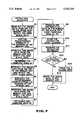
- FIG. 7shows a flowchart of an operation for extracting a predetermined line of words from the image data stored in the memory unit 27.
- the copier 10may read the required line as well as neighboring lines. In this case, the required line is extracted by performing this operation.
- the control unit 27sequentially supplies the image data stored in the image data memory unit 29 to the black data detecting unit 36, from the top to the bottom of the memory unit 29.
- the detecting unit 36detects the first black data in the image data supplied from the control unit 27 (step A1), and outputs the detecting signal to the control unit 27. This is, when the detecting unit 36 detects the black data of image data corresponding to the line F1 of a frame shown in FIG. 4, the detecting signal is output from the detecting unit 36 to the control 27.
- the control unit 27adds the address with respect to the column Y1, in which the first black data detected by the detecting unit 36 is stored to the predetermined number N (step A2).
- the address control unit 30sequentially designates the area of the memory unit 29 from the address with respect to the column Y2 which is obtained by adding to the predetermined number N toward the end address of the memory unit 29, and the control unit 27 supplies the image data to the detecting unit 36.
- the detecting unit 36detects the first black data of the image data obtained from the control unit 27 (step A3) and outputs the detected signal to the control unit 27.
- the control unit 27thereby counts a predetermined number M of the column starting with the column Y3 in which the first black data detected by the detecting unit 36 at the second detecting operation thereof, is stored and determines the sampling area S1 based on the number M (step A4).
- control unit 27sequentially supplies the image data stored from the bottom to the top of memory unit 29 to the detecting unit 36.
- the detecting unit 36detects the first black data of the image data supplied from the control unit 27 (step A5) and outputs the detected signal to the control unit 27. This is, when the detecting unit 36 detects the black data of image data corresponding to the line F2 of the frame shown in FIG. 4, the detecting signal is output from the detecting unit 36 to the control unit 27.
- the control unit 27subtracts the predetermined number N from the address with respect to the columns Y4 in which the first black data detected by the detecting unit 36 is stored (step A6).
- the address control unit 30under the control of the control unit 27, sequentially designates the area of the memory unit 29 from the address with respect to the column Y5 which is obtained by subtracting the predetermined number N toward the top address of the memory unit 29, and the control unit 27 supplies the image data to the detecting unit 36. Then, the detecting unit 36 detects the first black data of the image data supplied from the control unit 27 (step A7) and outputs the detected signal to the control unit 27.
- control unit 27counts a predetermined number M of column starting with the column Y6 in which the first black data detected by the detecting unit 36 in the second detecting operation is stored, and determines the sampling area S2 based on the number M (step A8).
- control unit 27supplies the image data stored in the area of the memory unit 29 corresponding to the sampling area S1, to the detecting unit 36.
- the detecting unit 36counts the black data in the image data supplied from the control unit 27 in every column, and outputs the count data to the numeric data memory unit 37. As a result, the distribution data of the number of black data stored in each of the rows in the sampling area S1, is obtained, as shown in FIG. 5.
- control unit 27supplies the image data which is stored in the area of the memory unit 29 corresponding to the sampling area S2, to the detecting unit 36.
- the detecting unit 36counts the black data of the image data supplied from the control unit 27 in every column, and outputs the count data to the numeric data memory unit 37.
- the distribution data of the number of black data stored in each of the rows in the sampling area S2is obtained (step A9).
- the count data stored in the numeric data memory unit 37is supplied sequentially to the extraction point judging unit 38, from the count data with respect to the center row Xc toward that with respect to both side rows.
- the judging unit 38detects the positions with respect to the row direction corresponding to the rows on each side of the center row Xc for which the count data is less than the predetermined number L0 and becomes more than the predetermined number L0 after the count data is less than number L0. Further, the judging unit 38 obtains the extraction point addresses x1, X2 corresponding to two points detected on each side of the center column Xc (step A10).
- the extraction point addresses x1 and x2are obtained with respect to each sampling area S1 and S2.
- the extraction point addresses x1 and x2 with respect to each sampling area S1 and S2are supplied to the arithmetic unit 39.
- the arithmetic unit 39obtains the extraction addresses corresponding to the line obtained by linking the extraction point address x1 between the sampling areas S1 and S2 and by linking the extraction point address X2 between the sampling areas S1 and S2. Therefore, the extraction addresses are thereby precisely obtained along the line spacing, even though the line spacing stored in the memory unit 29 is not parallel with the rows of the memory unit 29.
- the extraction addressesare output to the extraction address memory unit 40 (step A11), as shown in FIG. 6.
- the extraction addresses stored in the extraction address memory unit 40are supplied to the image data memory address control unit 30.
- the address control unit 30designates the area of the memory unit 29, under control of the control unit 27, by the addresses before and behind the extraction addresses with respect to the row direction.
- the image data stored in the area of memory unit 29 designated by the address control unit 30is supplied to the extraction point confirming unit 41 via the control unit 27.
- the confirming unit 41confirms whether or not the extraction addresses are appropriate by detecting whether or not the black data stored in areas designated by the addresses before and behind the extraction addresses is continuous through a predetermined number of the rows (step A12). That is, when the black data stored in areas designated by the addresses before and behind the extraction addresses is continuous through a predetermined number of the rows, the confirming unit 41 judges that the extraction addresses are in error.
- the confirming unit 41judges that the extraction addresses are in error, it outputs an NG signal to the alarm unit 42 and activates the buzzer (step A13). This completes the extraction operation.
- the address control unit 30, under control of control unit 27,designates the areas of the image data memory unit 29 with addresses between the top of the row address and the extraction address, between the extraction address and the end of the row address, in every column direction. Moreover, the control unit 27 writes the white data in the areas of memory unit 29 designated by the address control unit 30, thus erasing the image data stored in the areas of the memory unit 29 which are designated by the address control unit 30 (step A14). As a result, the image data except for the line to be read is erased.
- the extraction pointcan be determined based on the image data not of a part of the lines F1 and F2 of the frame but of the words shown in FIG. 4. Therefore, the line to be read can be precisely extracted, because of the exact detection of the space between the lines.
- the operatorsets the mode switch 16 to the print mode (PRINT), thus automatically setting the control unit in print mode.
- PRINTprint mode
- the encoder 32outputs the detecting signal representing the distance through which the housing has been moved in response to the rotation of the encoder disk 33.
- the address control unit 30designates the area of the memory unit 29 under the control of the control unit 27, and the control unit 27 supplies the image data stored in the memory unit 29 to the print unit 31 in response to the detecting signal outputted from the encoder 32.
- the print unit 31prints the image data supplied from the control unit 27 on the printing medium B for every set of image data stored in one row, being synchronized with the detecting signal outputted from the encoder 32.
- the number L0 with which the count data is compared to detect the extraction pointis predetermined.
- minimum numbers L1 and L2 of the black dataare detected with respect to the rows on each side of the center row Xc, by the detecting unit 36. Further, the control unit 27 produces numbers L01 and L02 with which the count data with respect to each of rows on each side of the center row Xc is compared, by adding the predetermined number to the minimum number L1, L2, respectively.
- the extraction pointcan be precisely detected.
- image data corresponding to one line of the wordscan be extracted from whole image data stored in the memory unit 29.
- image data corresponding to a plurality of the lines of the wordscan also be extracted from whole image data stored in the memory unit 29.
- the extraction operationis performed based on the least and largest extraction addresses with respect to the column direction.
Landscapes
- Engineering & Computer Science (AREA)
- Multimedia (AREA)
- Signal Processing (AREA)
- Facsimile Scanning Arrangements (AREA)
Abstract
Description
1. Field of the Invention
The present invention relates to a hand-held image reading apparatus for reading image information from a surface as it moves over the surface, and to a method of operating the apparatus.
2. Description of the Related Art
Various hand-held image reading apparatuses such as hand-held copiers, hand-held image scanners, and the like, have recently been put into practical use. These apparatuses read a predetermined width of image information from a surface, as they move over the surface. Therefore, they can read the part of an image corresponding to the distance they have moved. Some of these apparatuses are capable of changing the width of the reading area.
However, it is difficult for them to read only a single, required line of a document if the line spacing is narrow.
The present invention has been made in an attempt to solve the above-described problem of the conventional hand-held image reading apparatuses. The object is to provide a hand-held image reading apparatus which can read only a required part of an image, and a method of operating it.
To achieve the above-described object, the present invention provides a hand-held image reading apparatus comprising inputting means for inputting image data in response to a predetermined surface area containing image information memory means for storing the image data inputted by said inputting means extracting means for extracting a set of image data forming one line which exists in the center of image data stored in said memory means and outputting means for outputting the image data detected by said image data detecting means.
The above-described arrangement provides a particular advantage in that image data corresponding to only that part of an image required to be read can be precisely obtained, even if that part comprises only one line of a document with narrow line spacing between the line and adjacent lines and thus even if the not required part of the image as well as the required part of the image are stored in the memory means.
The object and other novel features of the present invention will become apparent from the following descriptions read in conjunction with the drawings, in which:
FIG. 1 is a perspective view of a hand-held manually sweepable copier according to a preferred embodiment of the invention;
FIG. 2 is a schematic block diagram of the internal arrangement of the hand-held manually sweepable copier shown in FIG. 1;
FIG. 3 is a view showing a state in which image information is read by the hand-held manually sweepable copier shown in FIG. 1;
FIG. 4 is a view showing a state in which image data is stored in the image data memory shown in FIG. 2 and a state in which a sampling area is determined by the control unit and the black data detecting unit shown in FIG. 2;
FIG. 5 is a view showing the distribution of black data counted by the black data detecting unit shown in FIG. 2;
FIG. 6 is a view showing a state in which extraction points are determined by the extraction point judging unit and the arithmetic unit shown in FIG. 2;
FIG. 7 is a flow chart for explaining an image data extracting process of the hand-held manually sweepable copier shown in FIG. 1; and
FIG. 8 is a view showing a state in which an extraction point is determined in another way by the control unit and the black data detecting unit shown in FIG. 2.
An embodiment of the present invention will now be described with reference to the accompanying drawings.
FIG. 1 shows a perspective view of a hand-held manually sweepable copier according to an embodiment of the present invention. Thecopier 10 comprises arectangular housing 11 which is small enough to be held by hand; areading section 12, provided at one end of thehousing 11, for optically reading image information from a surface A; aprinting section 13, provided at the other end of thehousing 11, for printing the image information read by thereading section 12;rubber rollers housing 11 near thereading section 12 and theprinting section 13, respectively, so that they protrude from respective ends of thehousing 11; amode switch 16, mounted on the side surface of thehousing 11, for switching between a power source (OFF), a read mode (INPUT) and a print mode (PRINT); and anoperation key 17 mounted on the front surface of thehousing 11 for starting a read or print operation.
In the read mode (INPUT) set by themode switch 16, when thehousing 11 is moved such that therollers 14 mounted near thereading section 12 are put into contact with the surface A, image information on the surface A is optically read as image data and stored in an internal memory (described later).
In the print mode (PRINT) set by themode switch 16, when thehousing 11 is moved such that therollers 15 mounted near theprinting section 13 are put into contact with a printing medium B, image data stored in the internal memory is printed on the printing medium B.
FIG. 2 shows an arrangement of electronic circuits of thecopier 10.
Thereading section 12 comprises animage sensor 20, anLED array 21, anLED driver 22 and areading encoder 23.
Theimage sensor 20 is a 64-dot line-type CCD (Couple Charged Device) with a width of 8 mm and a resolution of 8 dots/mm. The longitudinal axis of theimage sensor 20 is orthogonal to the direction in which thehousing 11 is moved across the surface A. FIG. 3 shows the surface A of a paper which characters are printed and frames F1 and F2 are provided. TheLED array 21 comprises a plurality of LEDs and its longitudinal axis is parallel to that ofimage sensor 20. TheLED driver 22 drives theLED array 21 so that it illuminates the surface A. Thereading encoder 23 has an encoder disk 24 which has a plurality of slits 25 formed radially at regular intervals, a detector 26 comprising an LED (not shown) and a photosensor (not shown) arranged adjacent to each other at opposing positions with the disk 24 disposed between the LED and the photosensor. The disk 24 is coupled to one of therollers 14 and is thus rotated by it. The detector 26 is situated so that light emitted from the LED is incident upon its photosensor through the slits 25 of the disk 24. When the disk 24 is rotated by moving thehousing 11 such that therollers 14 are put into contact with the surface A, the light emitted from the LED within the detector 26 is interrupted by the disk 24 at a rate corresponding to the moving speed of thehousing 11. Therefore, the detector 26 generates a detecting signal representing the distance through which thehousing 11 has been moved. The detecting signal generated by the detector 26 is outputted to acontrol unit 27 every time thehousing 11 is moved through a predetermined distance.
Theimage sensor 20 generates image signals corresponding to the image information on the surface A illuminated by theLED array 21, and outputs them to an imagesignal processing unit 28 on the basis of a control signal outputted from thecontrol unit 27. This control signal is based upon the detecting signal outputted from theencoder 23. The imagesignal processing unit 28 converts the image signals outputted from theimage sensor 20 into binary signals (black and white) and outputs the binary signals to controlunit 27 in 8 bit parallel as image data.
The image data outputted from theprocessing unit 28 is stored in an imagedata memory unit 29 via thecontrol unit 27. In FIG. 3, a rectangular thin line designates that area of the surface A which corresponds to a memory area of the imagedata memory unit 29 shown in FIG. 4. The imagedata memory unit 29 comprises a bit-map memory and has a storing area of 64 bits (cells) in the row direction X and 3200 bits (cells) in the column direction Y (shown in FIG. 4). That is, thememory unit 29 is capable of storing image data of 64 * 3200 bits obtained by moving thehousing 11 through 400 mm. When the image data outputted from the imagesignal processing unit 28, is stored in the imagedata memory unit 29, an image data memoryaddress control unit 30 designates addresses of thememory unit 29 under control of thecontrol unit 27.
The image data stored in thememory unit 29 to be printed on the printing medium B is supplied to aprinting unit 31 of theprinting section 13. Theprinting section 13 comprises aprinting unit 31 and aprinting encoder 32. Theprinting unit 31 comprises a thermal printing head (not shown), an ink ribbon (not shown) and a head driver (not shown). Theencoder 32 is constituted in the same way as thereading encoder 23 and comprises anencoder disk 33 which is rotated by one of therollers 15. It has a plurality ofslits 34 formed radially at regular intervals, and adetector 35. In the print mode (PRINT) set by themode switch 16, when the housing is moved such that therollers 15 are put into contact with the printing medium B theprinting unit 31, synchronized with a detecting signal outputted from theencoder 32, prints every set of image data stored in a row of thememory unit 29.
Moreover, the image data stored in the imagedata memory unit 29 is also supplied to a blackdata detecting unit 36 via thecontrol unit 27. The blackdata detecting unit 36 detects black data of the image data provided from thememory unit 29 and counts the number of black data stored in each row of thedata memory unit 29 in the column direction Y (as shown in FIG. 4 and 5).
When the image data stored in thememory unit 29 is sequentially supplied to the detectingunit 36 from the first column toward the last column, and from that in the last column toward that in the first column, the detectingunit 36, under the control of thecontrol unit 27, detects the first black data of the image data, which corresponds to a black line F1 or F2 representing a frame of the paper and which is stored in the column Y1 and outputs the first black data detecting signal to thecontrol unit 27. When thecontrol unit 27 is supplied with the first black data detecting signal from the detectingunit 36, thecontrol unit 27 increases or decreases an address in the column direction Y by a predetermined number N (shown in FIG. 4), with respect to a row in which the first black data is stored, and sequentially supplies the image data from thememory unit 29 to the detectingunit 36 with regard to the columns Y1 to Y2 or the columns Y4 to Y5, beginning with the column Y2 or Y5 designated by the address increased or decreased by the number N, the detectingunit 36 detects a white data continuing toward the last or the first of columns, respectively. Subsequently, the detectingunit 36 again detects, at column Y3 the first black data of the image data sequentially provided from thememory unit 29 and again outputs a detecting signal to thecontrol unit 27. During second storage of the black data, thecontrol unit 27 counts the predetermined number M of column starting with the column Y3 in which first black data is again detected by the detectingunit 36 and determines sampling areas S1 or S2 based on the number M (shown in FIG. 4). Thereafter, thecontrol unit 27 supplies the image data stored in the sampling areas S1 or S2 to the detectingunit 36. The detectingunit 36 then counts the number of black data in the image data supplied from thememory unit 29 in every column of thememory unit 29. That is, the detectingunit 36 produces distribution data of the number of black data stored in each of the columns with regard to the rows, and included in the sampling areas S1 and S2.
Each data count with respect to each column, obtained by the detectingunit 36, is stored in numericaldata memory unit 37. These count data are outputted to extractionpoint judging unit 38. The judgingunit 38 sequentially compares each count data outputted from the numericaldata memory unit 37 with a predetermined number L0, with regard to the black data counted from the center row shown by Xc in FIGS. 4 and 5 toward both side rows. Then, the judgingunit 38 detects the positions of the rows corresponding to the count data which become less than the predetermined number L0 for the first time and those which become more than the predetermined number L0 for the first time after the count data has been less than the predetermined number L0. Thus, the judgingunit 38 obtains the points midway between two positions detected on the basis of the count data with respect to each of the rows on each side of the center row Xc, and determines the row direction addresses of thememory unit 29 corresponding to the obtained points as extraction point addresses x1 and x2, shown in FIG. 5. The extraction point addresses x1 and x2 are determined with respect to each sampling area S1 and S2.
The extraction point addresses x1 and x2 in the sampling areas S1 and S2 determined by the judgingunit 38, are outputted to anarithmetic unit 39. Thearithmetic unit 39 obtains extraction addresses with respect to the row direction of the imagedata memory unit 29 in every column. These correspond to lines X1 and X2 shown in FIG. 6 and are obtained by linking the extraction point addresses x1 and x2 in the sampling area S1 with the extraction point address x1 or x2 in the sampling area S2. The extraction addresses obtained by thearithmetic unit 39 are outputted to an extractionaddress memory unit 40. The extraction addresses stored in theextraction address memory 40 are in turn outputted to the image data memoryaddress control unit 30.
When theaddress control unit 30, under control of thecontrol unit 27, designates areas of the imagedata memory unit 29 with addresses before and behind the extraction addresses of the row, the image data stored in the areas of thememory unit 29 designated by theaddress control unit 30 is supplied to an extractionpoint confirming unit 41 via thecontrol unit 27. The confirmingunit 41 judges if the extraction point is in error by detecting whether or not the black data continuously exists when data is obtained across the extraction line X1 or the extraction line X2 with respect to a particular column among a predetermined number of columns. That is, when the black data continuously exists across the extraction point X1, for example, the extraction point X1 is not considered as existing in the spacing between two adjacent lines and thus, is in error. When the confirmingunit 41 judges that the extraction point is in error, the confirmingunit 41 outputs an NG signal to drive analarm unit 42. Thealarm unit 42 then indicates that the extraction point is in error.
When theaddress control unit 30, under control of thecontrol unit 27, designates areas of the imagedata memory unit 29 with addresses between the top of the row direction address and the extraction address corresponding to the line X1, and between the end of the row direction address and the extraction address corresponding to the line X2 in every column, thecontrol unit 27 outputs white data tomemory unit 29 so as to erase the image data stored in the areas ofmemory unit 29 designated by theaddress control unit 30 and corresponding characters arranged in the adjacent lines.
The operation of thecopier 10 will now be described by referring to FIG. 2.
To read image information such as characters and images from the surface A, an operator sets themode switch 16 to the read mode (INPUT). Then, a power source is automatically turned on, and thecontrol unit 27 is automatically set in the read mode. Next, he places thehousing 11 on the surface A such that therollers 14 are put into contact with the surface A, and depresses theoperation key 17. In this condition, theLED array 21 is driven by theLED driver 22 to illuminate the surface. A. When thehousing 11 is manually moved across the surface A which contains image data to be read, theimage sensor 12 sequentially receives light reflected from the surface A.
Moreover, the encoder disk 24 is rotated by theroller 14 which is rotated corresponding to the movement of thehousing 11. Thus, thecontrol unit 27 receives the detecting signal representing the distance through which thehousing 11 has been moved across the surface A, from theencoder 23.
Theimage sensor 12 generates the image signal in response to the light reflected from the surface A and outputs the image signal corresponding to the detected signal outputted from theencoder 23 to the imagesignal processing unit 28. The imagesignal processing unit 28 converts the image signal outputted from theimage sensor 12 into binary data (black and white) and outputs the binary data to thecontrol unit 27 in 8-bit parallel as the image data. The image data memoryaddress control unit 30 designates the write-address of the imagedata memory unit 29 under the control of thecontrol unit 27, which in turn supplies the image data to thememory unit 29, to be stored. In this case, thecontrol unit 27 controls theaddress control unit 30 to increase the column direction address every time the detected signal is outputted from theencoder 23 and to increase the row direction address as the image data is outputted from the imagesignal processing unit 28. Then, thecontrol unit 27 awaits the next detected signal outputted from theencoder 23 after thecontrol unit 27 finishes writing the image data in thememory unit 29. This image data corresponds to the image signal outputted from the image sensor in response to one detected signal outputted fromencoder 23.
The above-described operation is repeated while thehousing 11 is moved. Therefore, the image data in response to the image information such as lines F1, F3 of a frame and words, on the surface A (shown in FIG. 3) over which the housing has been moved, is stored sequentially in thememory unit 29.
Now, the method by whichcopier 10 extracts the predetermined line of words from the image data read from surface A will be described.
FIG. 7 shows a flowchart of an operation for extracting a predetermined line of words from the image data stored in thememory unit 27. As shown in FIGS. 3 and 4, when the line spacing on the surface A is narrow, thecopier 10 may read the required line as well as neighboring lines. In this case, the required line is extracted by performing this operation.
Firstly, thecontrol unit 27 sequentially supplies the image data stored in the imagedata memory unit 29 to the blackdata detecting unit 36, from the top to the bottom of thememory unit 29. The detectingunit 36 detects the first black data in the image data supplied from the control unit 27 (step A1), and outputs the detecting signal to thecontrol unit 27. This is, when the detectingunit 36 detects the black data of image data corresponding to the line F1 of a frame shown in FIG. 4, the detecting signal is output from the detectingunit 36 to thecontrol 27. Subsequently, thecontrol unit 27 adds the address with respect to the column Y1, in which the first black data detected by the detectingunit 36 is stored to the predetermined number N (step A2). Next, theaddress control unit 30 sequentially designates the area of thememory unit 29 from the address with respect to the column Y2 which is obtained by adding to the predetermined number N toward the end address of thememory unit 29, and thecontrol unit 27 supplies the image data to the detectingunit 36. The detectingunit 36 detects the first black data of the image data obtained from the control unit 27 (step A3) and outputs the detected signal to thecontrol unit 27. Thecontrol unit 27 thereby counts a predetermined number M of the column starting with the column Y3 in which the first black data detected by the detectingunit 36 at the second detecting operation thereof, is stored and determines the sampling area S1 based on the number M (step A4).
Meanwhile, thecontrol unit 27 sequentially supplies the image data stored from the bottom to the top ofmemory unit 29 to the detectingunit 36. The detectingunit 36 detects the first black data of the image data supplied from the control unit 27 (step A5) and outputs the detected signal to thecontrol unit 27. This is, when the detectingunit 36 detects the black data of image data corresponding to the line F2 of the frame shown in FIG. 4, the detecting signal is output from the detectingunit 36 to thecontrol unit 27. Subsequently, thecontrol unit 27 subtracts the predetermined number N from the address with respect to the columns Y4 in which the first black data detected by the detectingunit 36 is stored (step A6). Further, theaddress control unit 30 under the control of thecontrol unit 27, sequentially designates the area of thememory unit 29 from the address with respect to the column Y5 which is obtained by subtracting the predetermined number N toward the top address of thememory unit 29, and thecontrol unit 27 supplies the image data to the detectingunit 36. Then, the detectingunit 36 detects the first black data of the image data supplied from the control unit 27 (step A7) and outputs the detected signal to thecontrol unit 27.
Thus, thecontrol unit 27 counts a predetermined number M of column starting with the column Y6 in which the first black data detected by the detectingunit 36 in the second detecting operation is stored, and determines the sampling area S2 based on the number M (step A8).
Thereafter, thecontrol unit 27 supplies the image data stored in the area of thememory unit 29 corresponding to the sampling area S1, to the detectingunit 36. The detectingunit 36 counts the black data in the image data supplied from thecontrol unit 27 in every column, and outputs the count data to the numericdata memory unit 37. As a result, the distribution data of the number of black data stored in each of the rows in the sampling area S1, is obtained, as shown in FIG. 5.
Likewise, thecontrol unit 27 supplies the image data which is stored in the area of thememory unit 29 corresponding to the sampling area S2, to the detectingunit 36. The detectingunit 36 counts the black data of the image data supplied from thecontrol unit 27 in every column, and outputs the count data to the numericdata memory unit 37. As a result, the distribution data of the number of black data stored in each of the rows in the sampling area S2 is obtained (step A9).
Subsequently, the count data stored in the numericdata memory unit 37 is supplied sequentially to the extractionpoint judging unit 38, from the count data with respect to the center row Xc toward that with respect to both side rows. The judgingunit 38 detects the positions with respect to the row direction corresponding to the rows on each side of the center row Xc for which the count data is less than the predetermined number L0 and becomes more than the predetermined number L0 after the count data is less than number L0. Further, the judgingunit 38 obtains the extraction point addresses x1, X2 corresponding to two points detected on each side of the center column Xc (step A10). The extraction point addresses x1 and x2 are obtained with respect to each sampling area S1 and S2.
The extraction point addresses x1 and x2 with respect to each sampling area S1 and S2 are supplied to thearithmetic unit 39. Thearithmetic unit 39 obtains the extraction addresses corresponding to the line obtained by linking the extraction point address x1 between the sampling areas S1 and S2 and by linking the extraction point address X2 between the sampling areas S1 and S2. Therefore, the extraction addresses are thereby precisely obtained along the line spacing, even though the line spacing stored in thememory unit 29 is not parallel with the rows of thememory unit 29. The extraction addresses are output to the extraction address memory unit 40 (step A11), as shown in FIG. 6.
Thereafter, the extraction addresses stored in the extractionaddress memory unit 40 are supplied to the image data memoryaddress control unit 30. Theaddress control unit 30 designates the area of thememory unit 29, under control of thecontrol unit 27, by the addresses before and behind the extraction addresses with respect to the row direction. Then, the image data stored in the area ofmemory unit 29 designated by theaddress control unit 30 is supplied to the extractionpoint confirming unit 41 via thecontrol unit 27. The confirmingunit 41 confirms whether or not the extraction addresses are appropriate by detecting whether or not the black data stored in areas designated by the addresses before and behind the extraction addresses is continuous through a predetermined number of the rows (step A12). That is, when the black data stored in areas designated by the addresses before and behind the extraction addresses is continuous through a predetermined number of the rows, the confirmingunit 41 judges that the extraction addresses are in error.
If the confirmingunit 41 judges that the extraction addresses are in error, it outputs an NG signal to thealarm unit 42 and activates the buzzer (step A13). This completes the extraction operation.
If the confirmingunit 41 judges that the extraction addresses are correct, theaddress control unit 30, under control ofcontrol unit 27, designates the areas of the imagedata memory unit 29 with addresses between the top of the row address and the extraction address, between the extraction address and the end of the row address, in every column direction. Moreover, thecontrol unit 27 writes the white data in the areas ofmemory unit 29 designated by theaddress control unit 30, thus erasing the image data stored in the areas of thememory unit 29 which are designated by the address control unit 30 (step A14). As a result, the image data except for the line to be read is erased.
In this manner, since the sampling areas S1 and S2 are determined based on the position of thememory unit 29, in which the black data detected for the second time is stored, the extraction point can be determined based on the image data not of a part of the lines F1 and F2 of the frame but of the words shown in FIG. 4. Therefore, the line to be read can be precisely extracted, because of the exact detection of the space between the lines.
An operation of printing the image data stored in thememory unit 29 will next be described.
To print the image data stored in thememory unit 29, the operator sets themode switch 16 to the print mode (PRINT), thus automatically setting the control unit in print mode. When the housing is placed on the printing medium B such that therollers 15 are in contact with the surface of the printing medium B, the thermal printing head is put into contact with the surface of the printing medium B with the ink-ribbon interposed. Then, the operator moveshousing 11 over the printing medium B with the operation key 17 depressed.
Meanwhile, theencoder disk 33 is rotated by therollers 15 according to the movement of thehousing 11. Theencoder 32 outputs the detecting signal representing the distance through which the housing has been moved in response to the rotation of theencoder disk 33.
Theaddress control unit 30 designates the area of thememory unit 29 under the control of thecontrol unit 27, and thecontrol unit 27 supplies the image data stored in thememory unit 29 to theprint unit 31 in response to the detecting signal outputted from theencoder 32. Theprint unit 31 prints the image data supplied from thecontrol unit 27 on the printing medium B for every set of image data stored in one row, being synchronized with the detecting signal outputted from theencoder 32.
Another embodiment of the extracting operation is described below by referring to FIG. 8.
In the extracting operation described above, the number L0 with which the count data is compared to detect the extraction point is predetermined.
However, in this embodiment, minimum numbers L1 and L2 of the black data are detected with respect to the rows on each side of the center row Xc, by the detectingunit 36. Further, thecontrol unit 27 produces numbers L01 and L02 with which the count data with respect to each of rows on each side of the center row Xc is compared, by adding the predetermined number to the minimum number L1, L2, respectively.
Therefore, since the numbers with which the count data are compared are different from those on each side of the center row, even though the black frame mark zone F3 whose width is reduced from the upper position to the lower position exists across the row direction in sampling area S1 or S2 and even though the numbers of the black data on each side of the center row Xc are different, as shown in FIG. 8, the extraction point can be precisely detected.
In the embodiments described above, image data corresponding to one line of the words can be extracted from whole image data stored in thememory unit 29. Likewise, image data corresponding to a plurality of the lines of the words can also be extracted from whole image data stored in thememory unit 29. In this case, the extraction operation is performed based on the least and largest extraction addresses with respect to the column direction.
Claims (20)
1. An image data processing apparatus, comprising:
inputting means for inputting image data in response to a predetermined area of a material having image information thereon;
memory means for storing the image data inputted by said inputting means;
counting means for counting the number of a predetermined kind of data of the image data stored in said memory means;
determining means for determining a space between a set of image data existing in a middle portion of the image data stored in said memory means and another set of image data stored in said memory means based on a result obtained by said counting means;
extracting means for extracting said set of the image data existing in the middle portion of the image data with respect to the space determined by said determining means; and
outputting means for outputting said set of image data extracted by said extraction means.
2. The image data processing apparatus of claim 1, wherein
said memory means includes a plurality of storing cells arranged in rows and columns;
said counting means includes means for counting the number of predetermined kind of data of the image data stored in one of the rows and columns of said memory means; and
said determining means includes:
comparing means for comparing the number of image data counted by said counting means with a reference number and,
detection means for detecting one of the rows and columns in which the space between the set of image data exists in the middle portion of the image data stored in said memory means and the other set of image data stored in said memory means, based on a result obtained by said comparing means.
3. The image data processing apparatus of claim 2, wherein
said comparing means sequentially compares the number of image data with the reference number from the number of image data with respect to the center of a row and column toward that with respect to each side one of a row and column, and includes means for detecting points of said memory means with respect to another one of row and column directions on both sides of the center of said memory means corresponding to the number of image data which is less than the reference number the first time, and which is thereafter more than the reference number; and
said detection means includes means for determining a point in the center between said two points detected by said comparing means for each side of the center of said memory means with respect to another one of the row and column directions, as an extraction point.
4. The image data processing apparatus of claim 2, wherein said comparing means includes reference number determining means for detecting a minimum number of the image data counted by said counting means and for determining the reference number based on the minimum number.
5. The image data processing apparatus of claim 1, wherein said inputting means includes image sensing means for producing binary data representing black and white, corresponding to the image information on the material; and wherein:
said memory means stores the binary data produced by said image sensing means; and
said counting means counts the number of binary data representing one of black and white data.
6. The image data processing apparatus of claim 1, further comprising housing means provided for at least said inputting means, for moving said inputting means on a surface of said material; and wherein:
said inputting means includes image sensing means having a sensing area of predetermined width extended in a direction orthogonal to that in which said inputting means is moved, for producing the image data corresponding to the image information on the surface over which said inputting means has been moved by said housing means.
7. The image data processing apparatus of claim 6, wherein:
said determining means includes means for determining a space between a set of image data existing in the middle portion with respect to the direction in which said sensing area of said image sensing means is extended and other sets of image data existing in the direction in which said sensing area of said image sensing means is extended, based on a result obtained by said counting means.
8. The image data processing apparatus of claim 7, wherein said memory means includes a plurality of storage cells arranged in rows and columns and stores each image data produced by said image sensing means corresponding to said sensing area, into said storage cells in every row;
said counting means includes means for counting the number of predetermined kinds of data of the image data stored in each row of said memory means; and
said determining means includes:
comparing means for comparing the number of image data counted by said counting means with a reference number; and
detection means for detecting the row in which the space between the set of image data existing in the center of the column direction of said memory means and other sets of the image data existing in the column direction of said memory means, based on a result obtained by said comparing means.
9. The image data processing apparatus of claim 8, wherein
said comparing means sequentially compares the number of image data with the reference number from the number of image data with respect to the center row toward that with respect to each side row, and includes means for detecting points of said memory means with respect to the column direction, corresponding to the number of image data which are less than the reference number the first time, and which are thereafter more than the reference number, on both sides of the center of said memory means with respect to the column direction; and
said detection means includes means for determining a center point between said two points detected by said comparing means on both sides of the center of said memory means with respect to the column direction, as an extraction point.
10. The image data processing apparatus of claim 9, wherein said comparing means includes reference number determining means for detecting a minimum number of image data counted by said counting means and determining the reference number based on this minimum number.
11. The image data processing apparatus of claim 7, wherein said inputting means includes binary data producing means for producing binary data representing black and white from the image data produced by said image sensing means;
wherein said memory means stores the binary data produced by said binary data producing means; and
said counting means counts the number of binary data representing one of black and white.
12. The image data processing apparatus of claim 6, wherein said housing means moves on the surface to be read, so as to move said inputting means on the surface to be read.
13. The image data processing apparatus of claim 12, wherein said housing means is manually moved on the surface to be read.
14. A method of operating an image data processing apparatus which includes a memory means, the method comprising the steps of:
inputting image data in response to a predetermined area of a surface containing image information thereon;
storing the inputted image data into said memory means;
counting the number of a predetermined kind of data of the image data stored in said memory means;
determining a space between a set of image data existing in a middle portion of the image data stored in the memory means based on a result obtained by said counting step;
extracting the image data existing in the middle portion of the image data with respect to the space; and
outputting the image data extracted by said extracting step.
15. The method of claim 14, wherein
said memory means includes a plurality of storing cells arranged in rows and columns; and
said counting step includes the step of:
counting the number of a predetermined kind of the image data stored in each row and each column of said memory means; and wherein
said determining step includes the steps of:
comparing the number of image data with a reference number; and
detecting one row and column in which a space exists between the set of image data existing in the middle portion of the image data stored in said memory means and another set of image data stored in said memory means, based on a result obtained by said comparing step.
16. The method of claim 15, wherein said comparing step includes the steps of;
sequentially comparing the number of image data with the reference number from the number of image data with respect to the center one of the row and the column toward that with respect to each side one of the row and column,
judging points of said memory means with respect to another one of the row and column directions on both sides of the center of said memory means with respect to another one of the row and column direction corresponding to the number of the image data which is less than the reference number the first time, and thereafter more than the reference number; and wherein
said detecting step includes the step of:
determining a point at the center between said two points detected by said comparing step for each side of the center of said memory means with respect to another one of the row and the column directions, as an extraction point.
17. The method of claim 15, wherein said comparing step includes the steps of:
detecting a minimum number of image data; and
determining the reference number based on said minimum number.
18. The method of claim 14, wherein:
said image data processing apparatus includes image sensing means having a sensing area of predetermined width and housing means provided for at least said image sensing means for moving said image sensing means; and
said determining step includes the step of:
determining the space between a set of image data existing in a middle portion with respect to a direction in which said sensing area of said image sensing means is extended and another set of image data existing in the direction in which said sensing area of said image sensing means is extended, based on a result obtained by said counting step.
19. The method of claim 18, wherein:
said memory means includes a plurality of storing cells arranged in rows and columns and stores each image data produced by said image sensing means corresponding to said sensing area, into said storing cells in every row;
said counting step includes the step of counting the number of the predetermined kind of image data stored in each of a number of rows of said memory means; and wherein:
said determining steps include the steps of:
comparing the number of image data with a reference number; and
detecting the row of said memory means in which the space between the set of image data existing in the middle portion of a column direction of said memory means and another set of image data existing in the column direction of said memory means, based on a result obtained by said comparing step.
20. The method of claim 19, wherein said comparing step includes the steps of:
sequentially comparing the number of image data with the reference number from the number of the image data with respect to the center row toward that with respect to each side row; and
judging points of said memory means with respect to the rows on both sides of the center of said memory means, in response to the number of image data which is less than the reference number for the first time, and which is thereafter more than the reference number, every side of the center of said memory means with respect to the column direction; and wherein
said detection step includes the step of:
determining the center point between said two points detected by said comparing step for each side of center of said memory means with respect to the column direction, as an extraction point.
Applications Claiming Priority (4)
| Application Number | Priority Date | Filing Date | Title |
|---|---|---|---|
| JP1029287AJP2864379B2 (en) | 1989-02-08 | 1989-02-08 | Image data reader |
| JP1-29287 | 1989-02-08 | ||
| JP1-188313 | 1989-07-20 | ||
| JP1188313AJP3018350B2 (en) | 1989-07-20 | 1989-07-20 | Image data reader |
Publications (1)
| Publication Number | Publication Date |
|---|---|
| US5083218Atrue US5083218A (en) | 1992-01-21 |
Family
ID=26367463
Family Applications (1)
| Application Number | Title | Priority Date | Filing Date |
|---|---|---|---|
| US07/477,232Expired - LifetimeUS5083218A (en) | 1989-02-08 | 1990-02-08 | Hand-held image reading apparatus |
Country Status (1)
| Country | Link |
|---|---|
| US (1) | US5083218A (en) |
Cited By (48)
| Publication number | Priority date | Publication date | Assignee | Title |
|---|---|---|---|---|
| WO1994000825A1 (en)* | 1992-06-19 | 1994-01-06 | Francis Olschafskie | Hand-held character-oriented scanner |
| US5574804A (en)* | 1990-12-21 | 1996-11-12 | Olschafskie; Francis | Hand-held scanner |
| US5896471A (en)* | 1995-04-27 | 1999-04-20 | Brother Kogyo Kabushiki Kaisha | Device for inputting and outputting image data |
| US5999666A (en)* | 1997-09-09 | 1999-12-07 | Gobeli; Garth W. | Device and method for optical scanning of text |
| US6081629A (en)* | 1997-09-17 | 2000-06-27 | Browning; Denton R. | Handheld scanner and accompanying remote access agent |
| US20010024290A1 (en)* | 2000-03-27 | 2001-09-27 | Hideyuki Toriyama | Image processing apparatus applicable to different copying types of color copying machines |
| US20030147103A1 (en)* | 2002-02-05 | 2003-08-07 | Hung Kuang Hui | Mechanical switching apparatus for resolution adjustment |
| US6629642B1 (en) | 1996-08-02 | 2003-10-07 | Symbol Technologies, Inc. | Data system and method for accessing a computer network using a collection of bar code symbols |
| US6747692B2 (en) | 1997-03-28 | 2004-06-08 | Symbol Technologies, Inc. | Portable multipurpose recording terminal and portable network server |
| US20040130749A1 (en)* | 2002-12-27 | 2004-07-08 | Brother Kogyo Kabushiki Kaisha | Data processing apparatus |
| US20050205671A1 (en)* | 2004-02-13 | 2005-09-22 | Tito Gelsomini | Cellular phone with scanning capability |
| US6965703B1 (en) | 1999-01-07 | 2005-11-15 | Topscan Ltd. | Optical scanner and software for correcting distorted images |
| US20060026078A1 (en)* | 2004-02-15 | 2006-02-02 | King Martin T | Capturing text from rendered documents using supplemental information |
| US20060041484A1 (en)* | 2004-04-01 | 2006-02-23 | King Martin T | Methods and systems for initiating application processes by data capture from rendered documents |
| US20060053097A1 (en)* | 2004-04-01 | 2006-03-09 | King Martin T | Searching and accessing documents on private networks for use with captures from rendered documents |
| US20060081714A1 (en)* | 2004-08-23 | 2006-04-20 | King Martin T | Portable scanning device |
| US20060098900A1 (en)* | 2004-09-27 | 2006-05-11 | King Martin T | Secure data gathering from rendered documents |
| US20060098899A1 (en)* | 2004-04-01 | 2006-05-11 | King Martin T | Handheld device for capturing text from both a document printed on paper and a document displayed on a dynamic display device |
| US20060136629A1 (en)* | 2004-08-18 | 2006-06-22 | King Martin T | Scanner having connected and unconnected operational behaviors |
| US20060256371A1 (en)* | 2004-12-03 | 2006-11-16 | King Martin T | Association of a portable scanner with input/output and storage devices |
| US20070279711A1 (en)* | 2004-12-03 | 2007-12-06 | King Martin T | Portable scanning and memory device |
| US20070300142A1 (en)* | 2005-04-01 | 2007-12-27 | King Martin T | Contextual dynamic advertising based upon captured rendered text |
| US20080137971A1 (en)* | 2004-04-01 | 2008-06-12 | Exbiblio B.V. | Method and System For Character Recognition |
| US20080141117A1 (en)* | 2004-04-12 | 2008-06-12 | Exbiblio, B.V. | Adding Value to a Rendered Document |
| US20080313172A1 (en)* | 2004-12-03 | 2008-12-18 | King Martin T | Determining actions involving captured information and electronic content associated with rendered documents |
| US20100165422A1 (en)* | 2008-12-26 | 2010-07-01 | Seiko Epson Corporation | Document Reading Apparatus |
| US20100278453A1 (en)* | 2006-09-15 | 2010-11-04 | King Martin T | Capture and display of annotations in paper and electronic documents |
| US20110022940A1 (en)* | 2004-12-03 | 2011-01-27 | King Martin T | Processing techniques for visual capture data from a rendered document |
| US20110025842A1 (en)* | 2009-02-18 | 2011-02-03 | King Martin T | Automatically capturing information, such as capturing information using a document-aware device |
| US20110043652A1 (en)* | 2009-03-12 | 2011-02-24 | King Martin T | Automatically providing content associated with captured information, such as information captured in real-time |
| US20110142371A1 (en)* | 2006-09-08 | 2011-06-16 | King Martin T | Optical scanners, such as hand-held optical scanners |
| US20110145068A1 (en)* | 2007-09-17 | 2011-06-16 | King Martin T | Associating rendered advertisements with digital content |
| US20110153653A1 (en)* | 2009-12-09 | 2011-06-23 | Exbiblio B.V. | Image search using text-based elements within the contents of images |
| US20110167075A1 (en)* | 2009-12-04 | 2011-07-07 | King Martin T | Using gestalt information to identify locations in printed information |
| US8447066B2 (en) | 2009-03-12 | 2013-05-21 | Google Inc. | Performing actions based on capturing information from rendered documents, such as documents under copyright |
| US8505090B2 (en) | 2004-04-01 | 2013-08-06 | Google Inc. | Archive of text captures from rendered documents |
| US8620083B2 (en) | 2004-12-03 | 2013-12-31 | Google Inc. | Method and system for character recognition |
| US8781228B2 (en) | 2004-04-01 | 2014-07-15 | Google Inc. | Triggering actions in response to optically or acoustically capturing keywords from a rendered document |
| US8799099B2 (en) | 2004-05-17 | 2014-08-05 | Google Inc. | Processing techniques for text capture from a rendered document |
| US8831365B2 (en) | 2004-02-15 | 2014-09-09 | Google Inc. | Capturing text from rendered documents using supplement information |
| US8892495B2 (en) | 1991-12-23 | 2014-11-18 | Blanding Hovenweep, Llc | Adaptive pattern recognition based controller apparatus and method and human-interface therefore |
| US9116890B2 (en) | 2004-04-01 | 2015-08-25 | Google Inc. | Triggering actions in response to optically or acoustically capturing keywords from a rendered document |
| US9143638B2 (en) | 2004-04-01 | 2015-09-22 | Google Inc. | Data capture from rendered documents using handheld device |
| US9268852B2 (en) | 2004-02-15 | 2016-02-23 | Google Inc. | Search engines and systems with handheld document data capture devices |
| US9275051B2 (en) | 2004-07-19 | 2016-03-01 | Google Inc. | Automatic modification of web pages |
| US9535563B2 (en) | 1999-02-01 | 2017-01-03 | Blanding Hovenweep, Llc | Internet appliance system and method |
| US9679179B2 (en) | 2015-08-31 | 2017-06-13 | I.R.I.S. | Method for processing information from a hand-held scanning device |
| US9692929B2 (en) | 2015-08-31 | 2017-06-27 | I.R.I.S. | Method and system for correction of an image from a hand-held scanning device |
Citations (4)
| Publication number | Priority date | Publication date | Assignee | Title |
|---|---|---|---|---|
| US4626925A (en)* | 1983-06-13 | 1986-12-02 | Nippon Kogaku K. K. | Photoelectric reader/printer with variable reading area |
| US4717965A (en)* | 1985-01-17 | 1988-01-05 | Ricoh Company, Ltd. | Portable image forming device |
| US4814898A (en)* | 1985-01-31 | 1989-03-21 | Canon Kabushiki Kaisha | Image signal processing system |
| US4931880A (en)* | 1988-04-25 | 1990-06-05 | Sharp Kabushiki Kaisha | Copying apparatus |
- 1990
- 1990-02-08USUS07/477,232patent/US5083218A/ennot_activeExpired - Lifetime
Patent Citations (4)
| Publication number | Priority date | Publication date | Assignee | Title |
|---|---|---|---|---|
| US4626925A (en)* | 1983-06-13 | 1986-12-02 | Nippon Kogaku K. K. | Photoelectric reader/printer with variable reading area |
| US4717965A (en)* | 1985-01-17 | 1988-01-05 | Ricoh Company, Ltd. | Portable image forming device |
| US4814898A (en)* | 1985-01-31 | 1989-03-21 | Canon Kabushiki Kaisha | Image signal processing system |
| US4931880A (en)* | 1988-04-25 | 1990-06-05 | Sharp Kabushiki Kaisha | Copying apparatus |
Cited By (100)
| Publication number | Priority date | Publication date | Assignee | Title |
|---|---|---|---|---|
| US5301243A (en)* | 1990-12-21 | 1994-04-05 | Francis Olschafskie | Hand-held character-oriented scanner with external view area |
| US5574804A (en)* | 1990-12-21 | 1996-11-12 | Olschafskie; Francis | Hand-held scanner |
| US8892495B2 (en) | 1991-12-23 | 2014-11-18 | Blanding Hovenweep, Llc | Adaptive pattern recognition based controller apparatus and method and human-interface therefore |
| WO1994000825A1 (en)* | 1992-06-19 | 1994-01-06 | Francis Olschafskie | Hand-held character-oriented scanner |
| US5896471A (en)* | 1995-04-27 | 1999-04-20 | Brother Kogyo Kabushiki Kaisha | Device for inputting and outputting image data |
| US6629642B1 (en) | 1996-08-02 | 2003-10-07 | Symbol Technologies, Inc. | Data system and method for accessing a computer network using a collection of bar code symbols |
| US6747692B2 (en) | 1997-03-28 | 2004-06-08 | Symbol Technologies, Inc. | Portable multipurpose recording terminal and portable network server |
| US5999666A (en)* | 1997-09-09 | 1999-12-07 | Gobeli; Garth W. | Device and method for optical scanning of text |
| US6707581B1 (en) | 1997-09-17 | 2004-03-16 | Denton R. Browning | Remote information access system which utilizes handheld scanner |
| US6081629A (en)* | 1997-09-17 | 2000-06-27 | Browning; Denton R. | Handheld scanner and accompanying remote access agent |
| US6965703B1 (en) | 1999-01-07 | 2005-11-15 | Topscan Ltd. | Optical scanner and software for correcting distorted images |
| US9535563B2 (en) | 1999-02-01 | 2017-01-03 | Blanding Hovenweep, Llc | Internet appliance system and method |
| US20010024290A1 (en)* | 2000-03-27 | 2001-09-27 | Hideyuki Toriyama | Image processing apparatus applicable to different copying types of color copying machines |
| US7116442B2 (en)* | 2000-03-27 | 2006-10-03 | Minolta Co., Ltd. | Image processing apparatus applicable to different copying types of color copying machines |
| US20030147103A1 (en)* | 2002-02-05 | 2003-08-07 | Hung Kuang Hui | Mechanical switching apparatus for resolution adjustment |
| US20040130749A1 (en)* | 2002-12-27 | 2004-07-08 | Brother Kogyo Kabushiki Kaisha | Data processing apparatus |
| US8169651B2 (en)* | 2002-12-27 | 2012-05-01 | Brother Kogyo Kabushiki Kaisha | Data processing apparatus for recognizing and processing content recorded on a recording medium |
| US20050205671A1 (en)* | 2004-02-13 | 2005-09-22 | Tito Gelsomini | Cellular phone with scanning capability |
| US7855812B2 (en)* | 2004-02-13 | 2010-12-21 | Texas Instruments Incorporated | Cellular phone with scanning capability |
| US9268852B2 (en) | 2004-02-15 | 2016-02-23 | Google Inc. | Search engines and systems with handheld document data capture devices |
| US20070011140A1 (en)* | 2004-02-15 | 2007-01-11 | King Martin T | Processing techniques for visual capture data from a rendered document |
| US20060041538A1 (en)* | 2004-02-15 | 2006-02-23 | King Martin T | Establishing an interactive environment for rendered documents |
| US20060047639A1 (en)* | 2004-02-15 | 2006-03-02 | King Martin T | Adding information or functionality to a rendered document via association with an electronic counterpart |
| US20060041590A1 (en)* | 2004-02-15 | 2006-02-23 | King Martin T | Document enhancement system and method |
| US20060061806A1 (en)* | 2004-02-15 | 2006-03-23 | King Martin T | Information gathering system and method |
| US20060036462A1 (en)* | 2004-02-15 | 2006-02-16 | King Martin T | Aggregate analysis of text captures performed by multiple users from rendered documents |
| US20060087683A1 (en)* | 2004-02-15 | 2006-04-27 | King Martin T | Methods, systems and computer program products for data gathering in a digital and hard copy document environment |
| US8831365B2 (en) | 2004-02-15 | 2014-09-09 | Google Inc. | Capturing text from rendered documents using supplement information |
| US8515816B2 (en) | 2004-02-15 | 2013-08-20 | Google Inc. | Aggregate analysis of text captures performed by multiple users from rendered documents |
| US20060119900A1 (en)* | 2004-02-15 | 2006-06-08 | King Martin T | Applying scanned information to identify content |
| US8214387B2 (en) | 2004-02-15 | 2012-07-03 | Google Inc. | Document enhancement system and method |
| US20060029296A1 (en)* | 2004-02-15 | 2006-02-09 | King Martin T | Data capture from rendered documents using handheld device |
| US20060026140A1 (en)* | 2004-02-15 | 2006-02-02 | King Martin T | Content access with handheld document data capture devices |
| US20060294094A1 (en)* | 2004-02-15 | 2006-12-28 | King Martin T | Processing techniques for text capture from a rendered document |
| US20060041828A1 (en)* | 2004-02-15 | 2006-02-23 | King Martin T | Triggering actions in response to optically or acoustically capturing keywords from a rendered document |
| US8019648B2 (en) | 2004-02-15 | 2011-09-13 | Google Inc. | Search engines and systems with handheld document data capture devices |
| US8005720B2 (en) | 2004-02-15 | 2011-08-23 | Google Inc. | Applying scanned information to identify content |
| US20060026078A1 (en)* | 2004-02-15 | 2006-02-02 | King Martin T | Capturing text from rendered documents using supplemental information |
| US7831912B2 (en) | 2004-02-15 | 2010-11-09 | Exbiblio B. V. | Publishing techniques for adding value to a rendered document |
| US7421155B2 (en) | 2004-02-15 | 2008-09-02 | Exbiblio B.V. | Archive of text captures from rendered documents |
| US7437023B2 (en) | 2004-02-15 | 2008-10-14 | Exbiblio B.V. | Methods, systems and computer program products for data gathering in a digital and hard copy document environment |
| US7818215B2 (en) | 2004-02-15 | 2010-10-19 | Exbiblio, B.V. | Processing techniques for text capture from a rendered document |
| US7593605B2 (en) | 2004-02-15 | 2009-09-22 | Exbiblio B.V. | Data capture from rendered documents using handheld device |
| US7596269B2 (en) | 2004-02-15 | 2009-09-29 | Exbiblio B.V. | Triggering actions in response to optically or acoustically capturing keywords from a rendered document |
| US7599844B2 (en) | 2004-02-15 | 2009-10-06 | Exbiblio B.V. | Content access with handheld document data capture devices |
| US7599580B2 (en) | 2004-02-15 | 2009-10-06 | Exbiblio B.V. | Capturing text from rendered documents using supplemental information |
| US7606741B2 (en) | 2004-02-15 | 2009-10-20 | Exbibuo B.V. | Information gathering system and method |
| US7702624B2 (en) | 2004-02-15 | 2010-04-20 | Exbiblio, B.V. | Processing techniques for visual capture data from a rendered document |
| US7707039B2 (en) | 2004-02-15 | 2010-04-27 | Exbiblio B.V. | Automatic modification of web pages |
| US7742953B2 (en) | 2004-02-15 | 2010-06-22 | Exbiblio B.V. | Adding information or functionality to a rendered document via association with an electronic counterpart |
| US7812860B2 (en) | 2004-04-01 | 2010-10-12 | Exbiblio B.V. | Handheld device for capturing text from both a document printed on paper and a document displayed on a dynamic display device |
| US9143638B2 (en) | 2004-04-01 | 2015-09-22 | Google Inc. | Data capture from rendered documents using handheld device |
| US8505090B2 (en) | 2004-04-01 | 2013-08-06 | Google Inc. | Archive of text captures from rendered documents |
| US9633013B2 (en) | 2004-04-01 | 2017-04-25 | Google Inc. | Triggering actions in response to optically or acoustically capturing keywords from a rendered document |
| US20060098899A1 (en)* | 2004-04-01 | 2006-05-11 | King Martin T | Handheld device for capturing text from both a document printed on paper and a document displayed on a dynamic display device |
| US20080137971A1 (en)* | 2004-04-01 | 2008-06-12 | Exbiblio B.V. | Method and System For Character Recognition |
| US8781228B2 (en) | 2004-04-01 | 2014-07-15 | Google Inc. | Triggering actions in response to optically or acoustically capturing keywords from a rendered document |
| US20060041484A1 (en)* | 2004-04-01 | 2006-02-23 | King Martin T | Methods and systems for initiating application processes by data capture from rendered documents |
| US9514134B2 (en) | 2004-04-01 | 2016-12-06 | Google Inc. | Triggering actions in response to optically or acoustically capturing keywords from a rendered document |
| US9116890B2 (en) | 2004-04-01 | 2015-08-25 | Google Inc. | Triggering actions in response to optically or acoustically capturing keywords from a rendered document |
| US20060053097A1 (en)* | 2004-04-01 | 2006-03-09 | King Martin T | Searching and accessing documents on private networks for use with captures from rendered documents |
| US9008447B2 (en) | 2004-04-01 | 2015-04-14 | Google Inc. | Method and system for character recognition |
| US8713418B2 (en) | 2004-04-12 | 2014-04-29 | Google Inc. | Adding value to a rendered document |
| US20080141117A1 (en)* | 2004-04-12 | 2008-06-12 | Exbiblio, B.V. | Adding Value to a Rendered Document |
| US9030699B2 (en) | 2004-04-19 | 2015-05-12 | Google Inc. | Association of a portable scanner with input/output and storage devices |
| US8799099B2 (en) | 2004-05-17 | 2014-08-05 | Google Inc. | Processing techniques for text capture from a rendered document |
| US9275051B2 (en) | 2004-07-19 | 2016-03-01 | Google Inc. | Automatic modification of web pages |
| US20060136629A1 (en)* | 2004-08-18 | 2006-06-22 | King Martin T | Scanner having connected and unconnected operational behaviors |
| US20060081714A1 (en)* | 2004-08-23 | 2006-04-20 | King Martin T | Portable scanning device |
| US8179563B2 (en) | 2004-08-23 | 2012-05-15 | Google Inc. | Portable scanning device |
| US20060098900A1 (en)* | 2004-09-27 | 2006-05-11 | King Martin T | Secure data gathering from rendered documents |
| US8953886B2 (en) | 2004-12-03 | 2015-02-10 | Google Inc. | Method and system for character recognition |
| US20060256371A1 (en)* | 2004-12-03 | 2006-11-16 | King Martin T | Association of a portable scanner with input/output and storage devices |
| US8081849B2 (en) | 2004-12-03 | 2011-12-20 | Google Inc. | Portable scanning and memory device |
| US20070279711A1 (en)* | 2004-12-03 | 2007-12-06 | King Martin T | Portable scanning and memory device |
| US8620083B2 (en) | 2004-12-03 | 2013-12-31 | Google Inc. | Method and system for character recognition |
| US8874504B2 (en) | 2004-12-03 | 2014-10-28 | Google Inc. | Processing techniques for visual capture data from a rendered document |
| US7990556B2 (en) | 2004-12-03 | 2011-08-02 | Google Inc. | Association of a portable scanner with input/output and storage devices |
| US20110022940A1 (en)* | 2004-12-03 | 2011-01-27 | King Martin T | Processing techniques for visual capture data from a rendered document |
| US20080313172A1 (en)* | 2004-12-03 | 2008-12-18 | King Martin T | Determining actions involving captured information and electronic content associated with rendered documents |
| US20070300142A1 (en)* | 2005-04-01 | 2007-12-27 | King Martin T | Contextual dynamic advertising based upon captured rendered text |
| US8600196B2 (en) | 2006-09-08 | 2013-12-03 | Google Inc. | Optical scanners, such as hand-held optical scanners |
| US20110142371A1 (en)* | 2006-09-08 | 2011-06-16 | King Martin T | Optical scanners, such as hand-held optical scanners |
| US20100278453A1 (en)* | 2006-09-15 | 2010-11-04 | King Martin T | Capture and display of annotations in paper and electronic documents |
| US20110145068A1 (en)* | 2007-09-17 | 2011-06-16 | King Martin T | Associating rendered advertisements with digital content |
| US20100165422A1 (en)* | 2008-12-26 | 2010-07-01 | Seiko Epson Corporation | Document Reading Apparatus |
| US8638363B2 (en) | 2009-02-18 | 2014-01-28 | Google Inc. | Automatically capturing information, such as capturing information using a document-aware device |
| US20110035656A1 (en)* | 2009-02-18 | 2011-02-10 | King Martin T | Identifying a document by performing spectral analysis on the contents of the document |
| US20110025842A1 (en)* | 2009-02-18 | 2011-02-03 | King Martin T | Automatically capturing information, such as capturing information using a document-aware device |
| US8418055B2 (en) | 2009-02-18 | 2013-04-09 | Google Inc. | Identifying a document by performing spectral analysis on the contents of the document |
| US8990235B2 (en) | 2009-03-12 | 2015-03-24 | Google Inc. | Automatically providing content associated with captured information, such as information captured in real-time |
| US9075779B2 (en) | 2009-03-12 | 2015-07-07 | Google Inc. | Performing actions based on capturing information from rendered documents, such as documents under copyright |
| US20110043652A1 (en)* | 2009-03-12 | 2011-02-24 | King Martin T | Automatically providing content associated with captured information, such as information captured in real-time |
| US8447066B2 (en) | 2009-03-12 | 2013-05-21 | Google Inc. | Performing actions based on capturing information from rendered documents, such as documents under copyright |
| US9081799B2 (en) | 2009-12-04 | 2015-07-14 | Google Inc. | Using gestalt information to identify locations in printed information |
| US20110167075A1 (en)* | 2009-12-04 | 2011-07-07 | King Martin T | Using gestalt information to identify locations in printed information |
| US20110153653A1 (en)* | 2009-12-09 | 2011-06-23 | Exbiblio B.V. | Image search using text-based elements within the contents of images |
| US9323784B2 (en) | 2009-12-09 | 2016-04-26 | Google Inc. | Image search using text-based elements within the contents of images |
| US9679179B2 (en) | 2015-08-31 | 2017-06-13 | I.R.I.S. | Method for processing information from a hand-held scanning device |
| US9692929B2 (en) | 2015-08-31 | 2017-06-27 | I.R.I.S. | Method and system for correction of an image from a hand-held scanning device |
Similar Documents
| Publication | Publication Date | Title |
|---|---|---|
| US5083218A (en) | Hand-held image reading apparatus | |
| EP0706896B1 (en) | Programmable encoder for carriage control | |
| EP0277964B1 (en) | Optical scanner including position sensors | |
| EP0011376B1 (en) | Photoelectric densitometer system | |
| US4959871A (en) | Image input/output apparatus | |
| US4349730A (en) | Data processing device for reading and processing visually observable information present on a data carrier | |
| US20100195129A1 (en) | Printer and method for detecting movement of object | |
| US6126341A (en) | Serial recording apparatus and method | |
| US4812918A (en) | Method and apparatus for scanning and digitizing optical images | |
| US4980776A (en) | Electronic copying machine having a line sensor in which the charge storage time is set based on image signals of the previous scan line | |
| JP3018350B2 (en) | Image data reader | |
| US6535145B1 (en) | Ideographic keyboard and method | |
| JP2815019B2 (en) | Character / mark detection device | |
| CN1069449A (en) | Ideograph typewriter and typewriting method | |
| JP2567893B2 (en) | Digital copier | |
| US20030042299A1 (en) | Data form for optical mark reading systems | |
| US20060097052A1 (en) | Method and apparatus for acquiring printing medium information using barcode sensors | |
| JP2534410Y2 (en) | Serial type image scanner printer | |
| JP3013244U (en) | Optical mark processing device | |
| JPH0521160Y2 (en) | ||
| JP2548019Y2 (en) | Serial type image scanner printer | |
| JP2788905B2 (en) | Paper detection device | |
| JPH09259196A (en) | Optical character reader and its control method | |
| JPS6014231A (en) | Original image reader | |
| JPS62163467A (en) | Image processor |
Legal Events
| Date | Code | Title | Description |
|---|---|---|---|
| AS | Assignment | Owner name:CASIO COMPUTER CO., LTD., A CORP. OF JAPAN, JAPAN Free format text:ASSIGNMENT OF ASSIGNORS INTEREST.;ASSIGNORS:TAKASU, AKIHIDE;SAGISAKA, ATSUSHI;REEL/FRAME:005229/0527 Effective date:19900129 | |
| STCF | Information on status: patent grant | Free format text:PATENTED CASE | |
| FEPP | Fee payment procedure | Free format text:PAYOR NUMBER ASSIGNED (ORIGINAL EVENT CODE: ASPN); ENTITY STATUS OF PATENT OWNER: LARGE ENTITY | |
| FPAY | Fee payment | Year of fee payment:4 | |
| FEPP | Fee payment procedure | Free format text:PAYOR NUMBER ASSIGNED (ORIGINAL EVENT CODE: ASPN); ENTITY STATUS OF PATENT OWNER: LARGE ENTITY Free format text:PAYER NUMBER DE-ASSIGNED (ORIGINAL EVENT CODE: RMPN); ENTITY STATUS OF PATENT OWNER: LARGE ENTITY | |
| FPAY | Fee payment | Year of fee payment:8 | |
| FPAY | Fee payment | Year of fee payment:12 |