US5082343A - Isolated optical coupler - Google Patents
Isolated optical couplerDownload PDFInfo
- Publication number
- US5082343A US5082343AUS07/630,925US63092590AUS5082343AUS 5082343 AUS5082343 AUS 5082343AUS 63092590 AUS63092590 AUS 63092590AUS 5082343 AUS5082343 AUS 5082343A
- Authority
- US
- United States
- Prior art keywords
- coupler
- collimating lens
- fiber amplifier
- optical
- disposed
- Prior art date
- Legal status (The legal status is an assumption and is not a legal conclusion. Google has not performed a legal analysis and makes no representation as to the accuracy of the status listed.)
- Expired - Lifetime
Links
Images
Classifications
- G—PHYSICS
- G02—OPTICS
- G02B—OPTICAL ELEMENTS, SYSTEMS OR APPARATUS
- G02B6/00—Light guides; Structural details of arrangements comprising light guides and other optical elements, e.g. couplings
- G02B6/24—Coupling light guides
- G02B6/42—Coupling light guides with opto-electronic elements
- H—ELECTRICITY
- H01—ELECTRIC ELEMENTS
- H01S—DEVICES USING THE PROCESS OF LIGHT AMPLIFICATION BY STIMULATED EMISSION OF RADIATION [LASER] TO AMPLIFY OR GENERATE LIGHT; DEVICES USING STIMULATED EMISSION OF ELECTROMAGNETIC RADIATION IN WAVE RANGES OTHER THAN OPTICAL
- H01S3/00—Lasers, i.e. devices using stimulated emission of electromagnetic radiation in the infrared, visible or ultraviolet wave range
- H01S3/05—Construction or shape of optical resonators; Accommodation of active medium therein; Shape of active medium
- H01S3/06—Construction or shape of active medium
- H01S3/063—Waveguide lasers, i.e. whereby the dimensions of the waveguide are of the order of the light wavelength
- H01S3/067—Fibre lasers
- H01S3/06754—Fibre amplifiers
- G—PHYSICS
- G02—OPTICS
- G02B—OPTICAL ELEMENTS, SYSTEMS OR APPARATUS
- G02B6/00—Light guides; Structural details of arrangements comprising light guides and other optical elements, e.g. couplings
- G02B6/24—Coupling light guides
- G02B6/42—Coupling light guides with opto-electronic elements
- G02B6/4201—Packages, e.g. shape, construction, internal or external details
- G02B6/4204—Packages, e.g. shape, construction, internal or external details the coupling comprising intermediate optical elements, e.g. lenses, holograms
- G02B6/4207—Packages, e.g. shape, construction, internal or external details the coupling comprising intermediate optical elements, e.g. lenses, holograms with optical elements reducing the sensitivity to optical feedback
- G02B6/4208—Packages, e.g. shape, construction, internal or external details the coupling comprising intermediate optical elements, e.g. lenses, holograms with optical elements reducing the sensitivity to optical feedback using non-reciprocal elements or birefringent plates, i.e. quasi-isolators
- G02B6/4209—Optical features
Definitions
- the present inventionrelates to an optical coupling arrangement and, more particularly, to an optically isolated coupling arrangement.
- Optical couplersare perhaps one of the most ubiquitous of all passive optical components and may be found in virtually any optical communication system.
- One use of optical couplers which is the subject of much current studyis in the field of fiber amplifiers, since these amplifiers require that both a communication signal and a pump signal be coupled into the amplifying medium, with the medium itself coupled to the optical signal path.
- the successful operation of fiber amplifiersmay be dependent upon the ability to couple maximum pump power into the amplifying gain medium, as well as the ability to control the multiple reflections present within the system.
- Iqbal et al.appearing in IEEE Photonics Technology Letters, Vol. 1, No. 10, October 1989 at pp. 334-6, the performance of systems utilizing erbium-doped fiber amplifiers is found to be degraded by the presence of signal-spontaneous beat noise and reflection-induced lasing within the amplifying medium.
- Iqbal et al.propose a system for multi-gigabit applications which utilizes a pair of isolators, with a first isolator located at the transmitter output and a second isolator located at the amplifier input. Although such isolators may improve the system performance, the size and complexity of the resultant system is also increased.
- Gimlett et al.propose an arrangement including a counter-propagating pumped fiber amplifier, with an optical isolator located at the amplifier input. A dichroic coupler is utilized to provide the pump signal to the fiber amplifier. As with the Iqbal et al. arrangement described above, the optical isolator and pump coupler of Gimlett et al. are separate, physically displaced devices.
- the present inventionrelates to an optical coupling arrangement and, more particularly, to an optically isolated coupling arrangement suitable for fiber amplifier applications.
- an isolated optical couplercomprises a first collimating lens (for receiving a first optical signal) and a second collimating lens, with a wavelength selective device disposed therebetween.
- the wavelength selective deviceis chosen so as to reflect the wavelength of the first optical signal and pass the wavelength of a second optical signal applied as an input to the coupler.
- An optical isolatoris included within the coupler and disposed in the signal path between the wavelength selective device and the second collimating lens. The isolator is utilized to essentially prevent reflected energy of the second signal from re-entering and degrading the performance of an attached transmitting device.
- the wavelength selective devicealso functions as a filter for the second signal. Therefore, when the coupler is utilized in fiber amplifier applications, the filter will essentially block any extraneous noise signals from entering the fiber amplifier, substantially reducing the effects of spontaneous emission within the fiber amplifier.
- the wavelength selective devicemay comprise a coating which is directly formed on an endface of the first lens, thus further reducing the number of individual components required in the coupler arrangement. Additionally, anti-reflective coatings may be disposed on various surfaces within the coupler to control internal reflections and thus improve return loss.
- an isolated couplermay be inserted in a transmission path between a transmitter and a fiber amplifier (i.e., "upstream" of the amplifier).
- the coupleris utilized to provide the pump signal input to the amplifier, while allowing the message signal from the transmitter to pass through the coupler essentially unimpeded.
- This particular embodimentis referred to as a "co-propagating" fiber amplifier, since the message signal and the pump signal pass through the amplifier in the same direction.
- an isolated coupler of the present inventionmay be inserted in a transmission path after a fiber amplifier (i.e., "downstream" of the amplifier).
- the coupleris formed so as to reflect a pump signal applied as an input thereto back into the fiber amplifier in the direction opposite of the message signal flow.
- the direction of propagation of the pump signaldoes not affect the performance of the amplifier, since the simultaneous existence of the message and pump signals within the amplifier is the only requirement for providing amplification of the message signal.
- This particular embodimentis referred to as a "counter-propagating" fiber amplifier as a result of the opposite signal flow directions.
- an alternative communication systemmay utilize a pair of isolated couplers formed in accordance with the present invention, with a fiber amplifier disposed therebetween.
- This particular embodimentis referred to as a "double-pumped" fiber amplifier, since both co- and counter-propagating pump signals are applied as inputs to the fiber amplifier.
- Such an arrangementis known to increase the pump power supplied to the fiber amplifier.
- an isolated optical couplermay be utilized simply to multiplex a pair of separate signals onto a single optical signal path.
- the "pump" signal input as defined aboveis replaced by a second message signal which is desired to be transmitted.
- a benefit of the present inventionis that the inclusion of the isolator within the coupler will essentially prevent reflected signals from re-entering one of the transmitters coupled thereto.
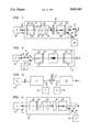
- FIG. 1illustrates a co-propagating pumped fiber amplifier utilizing an exemplary isolated optical coupler formed in accordance with the present invention
- FIG. 2illustrates a counter-propagating pumped fiber amplifier utilizing an exemplary isolated optical coupler formed in accordance with the present invention
- FIG. 3illustrates a double-pumped fiber amplifier utilizing a pair of exemplary isolated optical couplers formed in accordance with the present invention
- FIG. 4illustrates an optical transmission utilizing an isolated coupler of the present invention as a multiplexer for coupling a pair of optical inputs onto a single output transmission path.
- the following discussion of the present inventionincludes a number of embodiments related to fiber amplifier applications, with various isolated couplers of the invention including input and output fibers to provide the necessary attachments. It is to be understood that the various embodiments are exemplary only, and that the subject matter of the present invention may be provided in a substantially more integrated arrangement, for example, using integrated optical waveguides and optical amplifying gain medium disposed within an optical substrate. Additionally, it should be noted that the isolated coupling arrangement of the present invention is not limited to applications involving fiber amplifiers. There exist many other applications for such couplers, including arrangements where it is desired to multiplex a pair of high bit rate signals onto a common signal path, where an isolated coupler may be utilized to essentially prevent reflected message signals from re-entering the laser transmitter sources. One such exemplary system will be discussed below in association with FIG. 4.
- FIG. 1illustrates a particular fiber amplifier arrangement utilizing an exemplary isolated coupler 10 formed in accordance with the present invention.
- isolated coupler 10is utilized in association with a co-propagating fiber amplifier, that is, where isolated coupler 10 is inserted "upstream" of the fiber amplifier and the message signal and pump signal propagate in the same direction through the fiber amplifier.
- the isolated coupler arrangement of the present inventionmay also be utilized as a "downstream" counter-propagating coupler, as will be discussed in detail below in association with FIG. 2.
- isolated coupler 10is illustrated as being disposed in the optical signal path between a transmitting device 30 and fiber amplifier 32.
- Coupler 10utilizes as inputs a message signal M from transmitter 30 and a pump signal P from a pump source 34. Coupler 10 thus functions to multiplex the message and pump signals and direct both signals, via a single output fiber, into fiber amplifier 32. In this particular co-propagating embodiment, signals M and P will pass through fiber amplifier 32 in the same direction, as indicated by the arrows in FIG. 1.
- isolated coupler 10comprises a first collimating lens 12 and a second collimating lens 14.
- a wavelength selective device 16is disposed between first lens 12 and second lens 14.
- Device 16is chosen so as to reflect a first predetermined wavelength ⁇ P (i.e., pump wavelength) and transmit a second predetermined wavelength ⁇ M (i.e., message wavelength).
- coupler 10includes an optical isolator 20 disposed in the message signal path between second lens 14 and wavelength selective device 16.
- isolator 20is illustrated as comprising a Faraday rotator 22 disposed between a pair of birefringent plates 24,26.
- Such an isolatorfunctions to essentially prevent any signal passing through wavelength selective device 16 in the reverse direction from re-entering lens 14 and being coupled back into transmitting device 30.
- An additional AR coating 28may be included on the appropriate endface 18 of second lens 14 to essentially block reflections from surface 25 of plate 24.
- message signal Mpropagates along a first input fiber 36 and is coupled into second lens 14 of coupler 10.
- Message signal Mpasses through, in sequence, second lens 14, isolator 20, device 16 and first lens 12.
- Message signal Mthen exits coupler 10 and is coupled into an output fiber 40.
- Pump input signal Ppropagates along a second input fiber 38 and is coupled into first lens 12.
- Pump signal Pis reflected by device 16 and passes again through first lens 12, exits coupler 10 and is also coupled into output fiber 40. Therefore, message signal M and pump signal P will propagate simultaneously, in the same direction, along output fiber 40 and be applied as inputs to fiber amplifier 32.
- Fiber amplifier 32is appropriately doped (with erbium, for example) such that the presence of pump signal will stimulate emission and provide amplification of message signal M.
- An advantage of this particular "upstream" embodiment of the present invention, as mentioned above,is that wavelength selective device 16 may perform as a narrow bandpass filter which thus functions to reduce the propagation of unwanted signals through the coupler and into the amplifier. Therefore, spontaneous emission noise in amplifier 32 may be significantly reduced.
- FIG. 1illustrates, by way of example, a first AR coating 42 disposed on the appropriate endface 44 of first lens 12.
- a second AR coating 46is illustrated in FIG. 1 as being formed on the appropriate endface 48 of second lens 14.
- An additional coatingmay be formed on lens 12 at endface 47.
- various discrete anti-reflective componentssuch as appropriately-coated transparent plates and/or wedges, may be utilized in association with isolated coupler 10 to further reduce internal reflection problems.
- the arrangement of the present invention as described aboveprovides a degree of compactness and improved coupling efficiency by virtue of combining both functions within a single unit.
- coupler 50comprises a first collimating lens 52 and a second collimating lens 54, with a wavelength selective device 56 disposed therebetween.
- device 56is chosen so as to reflect the wavelength ⁇ P of pump signal P and transmit the wavelength ⁇ M of message signal M.
- wavelength selective device 56is illustrated as a coating directly formed on the appropriate endface 53 of first lens 52. It is to be understood that various wavelength selective devices, including but not limited to the discrete device as illustrated in FIG. 1 or the coating as illustrated in FIG. 2, may be used to perform this function.
- Coupler 50further comprises an optical isolator 58 which is disposed in the optical signal path between wavelength selective device 56 and second collimating lens 54.
- isolator 58 of coupler 50is utilized to minimize reflections of the message signal.
- isolator 58is merely represented by a single block, with a heavy arrow indicating the allowed direction of propagation. It is to be understood that isolator 58 may comprise components similar to isolator 20 of FIG. 1, or any other arrangement suitable of providing optical isolation at the desired wavelength.
- An AR coating 60is illustrated as disposed between isolator 58 and second lens 54 to essentially block reflections from surface 55 of plate 54.
- a pump signal P from a pump source 62is coupled by a first optical fiber 64 into first lens 52 of coupler 50.
- the pump signalis subsequently reflected, as illustrated, by coating 56 and passes a second time through first lens 52 where it then exits coupler 50 and is coupled into a second fiber 66.
- Fiber 66as shown, is coupled to fiber amplifier 32.
- Message signal M from a transmitter 30is coupled by a fiber 68 into fiber amplifier 32 such that both the message and pump signals exist simultaneously within fiber amplifier 32.
- coupler 50is defined as a counter-propagating coupler in that message signal M and pump signal P will propagate fiber amplifier 32 in opposite directions, illustrated by the arrows in FIG. 2.
- the amplified message signal M exiting fiber amplifier 32 along fiber 66will subsequently pass through coupler 50 essentially unimpeded, since wavelength selective device 56 is chosen to be transparent to the message wavelength ⁇ M .
- An advantage of the counter-propagating arrangement of FIG. 2is that the placement of wavelength selective coating 56 will essentially prevent any propagation of the pump signal along the output signal path.
- counter-propagating coupler 50 of FIG. 2may include additional AR devices to minimize internal reflections within coupler 50. Additional alignment considerations must also be addressed so as to maximize the coupling efficiency of the arrangement of the present invention, in particular, the alignment of the output fiber to the coupler. Such alignment techniques are considered to be well-known to those skilled in the art and need not be considered here.
- FIG. 3illustrates one such exemplary system utilizing a pair of isolated optical couplers formed in accordance with the present invention. Specifically, the arrangement combines the systems of FIGS. 1 and 2, with co-propagating first isolated coupler 10 disposed in the signal path between transmitter 30 and fiber amplifier 32. As discussed above in association with FIG. 1, a pump signal P from source 34 is applied as an input to coupler 10 such that message signal M and pump signal P may be applied as simultaneous inputs to fiber amplifier 32.
- Counter-propagating second isolated coupler 50is disposed in the signal path at the output of fiber amplifier 32 wherein a pump signal P from source 62 is applied as an input to coupler 50 and is subsequently reflected back into fiber amplifier 32.
- a pump signal P from source 62is applied as an input to coupler 50 and is subsequently reflected back into fiber amplifier 32.
- the co-existence of both pump sources with the message signalresults in increased amplification.
- the embodiment of FIG. 3may be thought of as a pump sparing arrangement, providing a back-up pump upon failure of either source 34 or 62.
- FIG. 4illustrates a communication arrangement 70 for multiplexing a pair of separate signal sources onto one output signal path.
- an isolated coupler 72 as formed in accordance with the present inventionis utilized with a pair of separate signal source 74 and 76.
- a first input signal T 1 at a wavelength ⁇ 1 from a first transmitter 74 and a second input signal T 2 at a different wavelength ⁇ 2 from a second transmitter 76are applied as separate inputs to coupler 72 and combined to propagate simultaneously along an output signal path 78.
- first signal T 1propagates along an optical fiber 80 and is applied as an input to a first collimating lens 82.
- Second signal T 2propagates along an optical fiber 84 and is coupled to second collimating lens 86 of coupler 72. Disposed between second lens 86 and first lens 82 are, in sequence, an optical isolator 88 and a wavelength selective device 90. Anti-reflective means 92 may be inserted between second lens 86 and isolator 88 to reduce reflections within coupler 72.
- wavelength selective device 90is chosen so as to reflect wavelength ⁇ 1 associated with signal T 1 and transmit wavelength ⁇ 2 associated with signal T 2 . Therefore, coupler 72 as shown is capable of coupling both input signals into one output signal path 78.
- the inclusion of isolator 88 in accordance with the present inventionprotects second transmitter 76 from reflected signals, which may seriously degrade the performance of some transmitters, particularly high speed laser transmitters.
Landscapes
- Physics & Mathematics (AREA)
- Optics & Photonics (AREA)
- Electromagnetism (AREA)
- General Physics & Mathematics (AREA)
- Engineering & Computer Science (AREA)
- Plasma & Fusion (AREA)
- Lasers (AREA)
- Optical Communication System (AREA)
- Optical Couplings Of Light Guides (AREA)
Abstract
Description
Claims (16)
Priority Applications (5)
| Application Number | Priority Date | Filing Date | Title |
|---|---|---|---|
| US07/630,925US5082343A (en) | 1990-12-20 | 1990-12-20 | Isolated optical coupler |
| DE69124962TDE69124962T2 (en) | 1990-12-20 | 1991-12-04 | Optical coupler with optical isolator |
| EP91311300AEP0492850B1 (en) | 1990-12-20 | 1991-12-04 | Isolated optical coupler |
| KR1019910022716AKR100243447B1 (en) | 1990-12-20 | 1991-12-12 | Isolated optical coupler |
| JP3354524AJP2665097B2 (en) | 1990-12-20 | 1991-12-20 | Optical coupler |
Applications Claiming Priority (1)
| Application Number | Priority Date | Filing Date | Title |
|---|---|---|---|
| US07/630,925US5082343A (en) | 1990-12-20 | 1990-12-20 | Isolated optical coupler |
Publications (1)
| Publication Number | Publication Date |
|---|---|
| US5082343Atrue US5082343A (en) | 1992-01-21 |
Family
ID=24529138
Family Applications (1)
| Application Number | Title | Priority Date | Filing Date |
|---|---|---|---|
| US07/630,925Expired - LifetimeUS5082343A (en) | 1990-12-20 | 1990-12-20 | Isolated optical coupler |
Country Status (5)
| Country | Link |
|---|---|
| US (1) | US5082343A (en) |
| EP (1) | EP0492850B1 (en) |
| JP (1) | JP2665097B2 (en) |
| KR (1) | KR100243447B1 (en) |
| DE (1) | DE69124962T2 (en) |
Cited By (38)
| Publication number | Priority date | Publication date | Assignee | Title |
|---|---|---|---|---|
| US5208876A (en)* | 1991-11-01 | 1993-05-04 | E-Tek Dynamics, Inc. | Optical isolator |
| US5216737A (en)* | 1991-02-28 | 1993-06-01 | U.S. Philips Corporation | Optoelectronic device comprising a semiconductor laser and an optical isolator |
| US5355249A (en)* | 1992-04-21 | 1994-10-11 | Matsushita Electric Industrial Co., Ltd. | Optical passive components |
| US5539577A (en)* | 1995-05-16 | 1996-07-23 | Jds Fitel, Inc. | Means to lessen unwanted reflections in an optical device |
| US5555330A (en)* | 1994-12-21 | 1996-09-10 | E-Tek Dynamics, Inc. | Wavelength division multiplexed coupler with low crosstalk between channels and integrated coupler/isolator device |
| US5566259A (en)* | 1994-12-13 | 1996-10-15 | E-Tek Dynamics, Inc. | Dual stage optical device with low polarization mode dispersion |
| WO1996032659A1 (en)* | 1995-04-10 | 1996-10-17 | Jds Fitel Inc. | Integrated optical isolator |
| US5581640A (en)* | 1994-12-13 | 1996-12-03 | E-Tek Dynamics, Inc. | Dual stage optical device with low polarization mode dispersion and wavelength insensitivity |
| US5594821A (en)* | 1995-04-10 | 1997-01-14 | Jds Fitel Inc. | Integrated optical isolator |
| US5642448A (en)* | 1994-12-21 | 1997-06-24 | E-Tek Dynamics, Inc. | Integrable fiberoptic coupler and resulting devices and systems |
| US5657155A (en)* | 1996-08-16 | 1997-08-12 | Jds Fitel Inc. | Optical tap coupler device |
| US5680237A (en)* | 1995-11-16 | 1997-10-21 | Jds Fitel Inc. | Graded index lens system and method for coupling light |
| EP0848277A1 (en)* | 1996-12-03 | 1998-06-17 | Jds Fitel Inc. | Optical isolator |
| US6031952A (en)* | 1998-11-13 | 2000-02-29 | Dicon Fiberoptics, Inc. | Broadband coupler |
| US6078710A (en)* | 1998-04-02 | 2000-06-20 | Oplink Communications, Inc. | Method and system for providing a multi-channel optical filter |
| US6167174A (en)* | 1998-10-27 | 2000-12-26 | Adc Telecommunications, Inc. | Multiple port, fiber optic isolator |
| US6168319B1 (en) | 1999-08-05 | 2001-01-02 | Corning Incorporated | System and method for aligning optical fiber collimators |
| US6353497B1 (en) | 2000-03-03 | 2002-03-05 | Optical Coating Laboratory, Inc. | Integrated modular optical amplifier |
| US6433924B1 (en) | 2000-11-14 | 2002-08-13 | Optical Coating Laboratory, Inc. | Wavelength-selective optical amplifier |
| US6546168B1 (en)* | 1999-12-10 | 2003-04-08 | Finisar Corporation | Integrated isolator fused coupler method and apparatus |
| CN1311277C (en)* | 2002-10-15 | 2007-04-18 | 奥普林克通信公司 | Reflective variable attenuator and split monitor |
| CN1312500C (en)* | 2002-05-03 | 2007-04-25 | 奥普林克通信公司 | Optical mixer including four isolated end port |
| US8602659B2 (en)* | 2012-04-16 | 2013-12-10 | Hon Hai Precision Industry Co., Ltd. | Optical fiber connector |
| US20140147129A1 (en)* | 2010-09-27 | 2014-05-29 | Alcatel-Lucent | Photonic integrated circuit for wavelength division multiplexing |
| US9791627B1 (en) | 2016-04-08 | 2017-10-17 | Dicon Fiberoptics, Inc. | Integrated optical components with wavelength tuning and power isolation functions |
| US20230137107A1 (en)* | 2021-10-28 | 2023-05-04 | Bolt Medical, Inc. | High bandwidth energy source for improved transmission through optical fiber for intravascular lithotripsy |
| CN116316010A (en)* | 2023-03-28 | 2023-06-23 | 长飞(武汉)光系统股份有限公司 | A Few-mode Fiber Amplifier Structure |
| US11839391B2 (en) | 2021-12-14 | 2023-12-12 | Bolt Medical, Inc. | Optical emitter housing assembly for intravascular lithotripsy device |
| US11903642B2 (en) | 2020-03-18 | 2024-02-20 | Bolt Medical, Inc. | Optical analyzer assembly and method for intravascular lithotripsy device |
| US11911574B2 (en) | 2019-06-26 | 2024-02-27 | Boston Scientific Scimed, Inc. | Fortified balloon inflation fluid for plasma system to disrupt vascular lesions |
| US20240189030A1 (en)* | 2021-10-28 | 2024-06-13 | Bolt Medical, Inc. | High bandwidth energy source for improved transmission through optical fiber for intravascular lithotripsy |
| US12016610B2 (en) | 2020-12-11 | 2024-06-25 | Bolt Medical, Inc. | Catheter system for valvuloplasty procedure |
| US12102384B2 (en) | 2019-11-13 | 2024-10-01 | Bolt Medical, Inc. | Dynamic intravascular lithotripsy device with movable energy guide |
| US12207870B2 (en) | 2020-06-15 | 2025-01-28 | Boston Scientific Scimed, Inc. | Spectroscopic tissue identification for balloon intravascular lithotripsy guidance |
| US12274497B2 (en) | 2019-12-18 | 2025-04-15 | Bolt Medical, Inc. | Multiplexer for laser-driven intravascular lithotripsy device |
| US12274485B2 (en) | 2021-01-12 | 2025-04-15 | Bolt Medical, Inc. | Balloon assembly for valvuloplasty catheter system |
| US12295654B2 (en) | 2020-06-03 | 2025-05-13 | Boston Scientific Scimed, Inc. | System and method for maintaining balloon integrity within intravascular lithotripsy device with plasma generator |
| US12402946B2 (en) | 2019-06-19 | 2025-09-02 | Boston Scientific Scimed, Inc. | Breakdown of laser pulse energy for breakup of vascular calcium |
Families Citing this family (2)
| Publication number | Priority date | Publication date | Assignee | Title |
|---|---|---|---|---|
| KR0171861B1 (en)* | 1996-03-11 | 1999-03-30 | 김광호 | Reverse-current breaker |
| DE19725720A1 (en)* | 1997-06-18 | 1998-12-24 | Alsthom Cge Alcatel | Optical isolator and wavelength multiplexer module with integrated optical isolator |
Citations (17)
| Publication number | Priority date | Publication date | Assignee | Title |
|---|---|---|---|---|
| US4213677A (en)* | 1976-10-13 | 1980-07-22 | Nippon Selfoc Company, Limited | Light coupling and branching device using light focusing transmission body |
| JPS57169289A (en)* | 1981-04-13 | 1982-10-18 | Nec Corp | Optical fiber laser light input device |
| US4358851A (en)* | 1980-02-28 | 1982-11-09 | Xerox Corporation | Fiber optic laser device and light emitter utilizing the device |
| US4405199A (en)* | 1981-02-11 | 1983-09-20 | Ogle James W | Method for enhancing signals transmitted over optical fibers |
| US4515431A (en)* | 1982-08-11 | 1985-05-07 | The Board Of Trustees Of The Leland Stanford Junior University | Fiber optic amplifier |
| US4718055A (en)* | 1985-09-17 | 1988-01-05 | Siemens Aktiengesellschaft | Wave-division multiplex component for an optical network comprising monomode transmission fibers |
| US4767171A (en)* | 1986-03-27 | 1988-08-30 | Siemens Aktiengesellschaft | Transmission and reception module for a bidirectional communication network |
| JPH01145885A (en)* | 1987-12-01 | 1989-06-07 | Matsushita Electric Ind Co Ltd | optical amplifier |
| US4880289A (en)* | 1983-12-16 | 1989-11-14 | Hitachi, Ltd. | Two-way optical transmission system |
| EP0343489A2 (en)* | 1988-05-20 | 1989-11-29 | Oki Electric Industry Company, Limited | Optical amplifier module |
| US4893890A (en)* | 1988-05-04 | 1990-01-16 | Lutes George F | Low-loss, high-isolation, fiber-optic isolator |
| EP0352974A2 (en)* | 1988-07-29 | 1990-01-31 | AT&T Corp. | Polarization independent optical amplifier apparatus |
| US4904043A (en)* | 1988-06-15 | 1990-02-27 | American Telephone And Telegraph Company, At&T Bell Laboratories | Optical data link dual wavelength coupler |
| US4947134A (en)* | 1987-10-30 | 1990-08-07 | American Telephone And Telegraph Company | Lightwave systems using optical amplifiers |
| US4997252A (en)* | 1988-11-02 | 1991-03-05 | Kabushiki Kaisha Toshiba | Optical fiber communication connection device |
| US5003623A (en)* | 1983-06-16 | 1991-03-26 | Trw Inc. | Bimodal intrusion detection in an optical fiber communication system using graded index fiber |
| US5007698A (en)* | 1989-08-15 | 1991-04-16 | Fujitsu Limited | Optical fiber amplifier/multiplexer |
Family Cites Families (4)
| Publication number | Priority date | Publication date | Assignee | Title |
|---|---|---|---|---|
| JPS6051684B2 (en)* | 1976-06-30 | 1985-11-15 | 株式会社東芝 | Optical fiber splitter/optical coupler |
| JPS606481B2 (en)* | 1978-01-11 | 1985-02-19 | 松下電器産業株式会社 | light splitter mixer |
| GB8512980D0 (en)* | 1985-05-22 | 1985-06-26 | Pa Consulting Services | Fibre optic transmissions systems |
| JPH02281833A (en)* | 1989-04-24 | 1990-11-19 | Nippon Telegr & Teleph Corp <Ntt> | Optical wavelength multiplex transmission system |
- 1990
- 1990-12-20USUS07/630,925patent/US5082343A/ennot_activeExpired - Lifetime
- 1991
- 1991-12-04EPEP91311300Apatent/EP0492850B1/ennot_activeExpired - Lifetime
- 1991-12-04DEDE69124962Tpatent/DE69124962T2/ennot_activeExpired - Lifetime
- 1991-12-12KRKR1019910022716Apatent/KR100243447B1/ennot_activeExpired - Fee Related
- 1991-12-20JPJP3354524Apatent/JP2665097B2/ennot_activeExpired - Fee Related
Patent Citations (18)
| Publication number | Priority date | Publication date | Assignee | Title |
|---|---|---|---|---|
| US4213677A (en)* | 1976-10-13 | 1980-07-22 | Nippon Selfoc Company, Limited | Light coupling and branching device using light focusing transmission body |
| US4358851A (en)* | 1980-02-28 | 1982-11-09 | Xerox Corporation | Fiber optic laser device and light emitter utilizing the device |
| US4405199A (en)* | 1981-02-11 | 1983-09-20 | Ogle James W | Method for enhancing signals transmitted over optical fibers |
| JPS57169289A (en)* | 1981-04-13 | 1982-10-18 | Nec Corp | Optical fiber laser light input device |
| US4515431A (en)* | 1982-08-11 | 1985-05-07 | The Board Of Trustees Of The Leland Stanford Junior University | Fiber optic amplifier |
| US5003623A (en)* | 1983-06-16 | 1991-03-26 | Trw Inc. | Bimodal intrusion detection in an optical fiber communication system using graded index fiber |
| US4880289A (en)* | 1983-12-16 | 1989-11-14 | Hitachi, Ltd. | Two-way optical transmission system |
| US4718055A (en)* | 1985-09-17 | 1988-01-05 | Siemens Aktiengesellschaft | Wave-division multiplex component for an optical network comprising monomode transmission fibers |
| US4767171A (en)* | 1986-03-27 | 1988-08-30 | Siemens Aktiengesellschaft | Transmission and reception module for a bidirectional communication network |
| US4947134A (en)* | 1987-10-30 | 1990-08-07 | American Telephone And Telegraph Company | Lightwave systems using optical amplifiers |
| JPH01145885A (en)* | 1987-12-01 | 1989-06-07 | Matsushita Electric Ind Co Ltd | optical amplifier |
| US4893890A (en)* | 1988-05-04 | 1990-01-16 | Lutes George F | Low-loss, high-isolation, fiber-optic isolator |
| EP0343489A2 (en)* | 1988-05-20 | 1989-11-29 | Oki Electric Industry Company, Limited | Optical amplifier module |
| US4995696A (en)* | 1988-05-20 | 1991-02-26 | Oki Electric Industry Co., Ltd. | Optical amplifier module |
| US4904043A (en)* | 1988-06-15 | 1990-02-27 | American Telephone And Telegraph Company, At&T Bell Laboratories | Optical data link dual wavelength coupler |
| EP0352974A2 (en)* | 1988-07-29 | 1990-01-31 | AT&T Corp. | Polarization independent optical amplifier apparatus |
| US4997252A (en)* | 1988-11-02 | 1991-03-05 | Kabushiki Kaisha Toshiba | Optical fiber communication connection device |
| US5007698A (en)* | 1989-08-15 | 1991-04-16 | Fujitsu Limited | Optical fiber amplifier/multiplexer |
Non-Patent Citations (8)
| Title |
|---|
| "An 11 Gbit/s, 151 km Transmission Experiment . . .", IEEE Photonics Technology Letters, vol. 1, No. 10, Oct. 1989, pp. 334-336, M. Z. Iqbal et al. |
| "Direct Detection Transmission Experiments . . .", Electronics Letters, vol. 25, No. 3, Feb. 1989, pp. 236-238, D. J. Malyon et al. |
| "Impact of Multiple Reflection Noise . . .", Electronics Letters, vol. 25, No. 20, Sep. 1989, pp. 1393-1394, J. L. Bimlett et al. |
| "Noise Performance of Erbium-Doped Fiber Amplifier . . .", IEEE Phot. Tech. Lett., vol. 1, No. 11, Nov. 1989, pp. 367-369, C. R. Giles et al. |
| An 11 Gbit/s, 151 km Transmission Experiment . . . , IEEE Photonics Technology Letters, vol. 1, No. 10, Oct. 1989, pp. 334 336, M. Z. Iqbal et al.* |
| Direct Detection Transmission Experiments . . . , Electronics Letters, vol. 25, No. 3, Feb. 1989, pp. 236 238, D. J. Malyon et al.* |
| Impact of Multiple Reflection Noise . . . , Electronics Letters, vol. 25, No. 20, Sep. 1989, pp. 1393 1394, J. L. Bimlett et al.* |
| Noise Performance of Erbium Doped Fiber Amplifier . . . , IEEE Phot. Tech. Lett., vol. 1, No. 11, Nov. 1989, pp. 367 369, C. R. Giles et al.* |
Cited By (46)
| Publication number | Priority date | Publication date | Assignee | Title |
|---|---|---|---|---|
| US5216737A (en)* | 1991-02-28 | 1993-06-01 | U.S. Philips Corporation | Optoelectronic device comprising a semiconductor laser and an optical isolator |
| WO1993009455A1 (en)* | 1991-11-01 | 1993-05-13 | E-Tek Dynamics, Inc. | An improved optical isolator |
| US5208876A (en)* | 1991-11-01 | 1993-05-04 | E-Tek Dynamics, Inc. | Optical isolator |
| USRE35575E (en)* | 1991-11-01 | 1997-07-29 | E-Tek Dynamics, Inc. | Optical isolator |
| US5355249A (en)* | 1992-04-21 | 1994-10-11 | Matsushita Electric Industrial Co., Ltd. | Optical passive components |
| US5581640A (en)* | 1994-12-13 | 1996-12-03 | E-Tek Dynamics, Inc. | Dual stage optical device with low polarization mode dispersion and wavelength insensitivity |
| US5566259A (en)* | 1994-12-13 | 1996-10-15 | E-Tek Dynamics, Inc. | Dual stage optical device with low polarization mode dispersion |
| US5642448A (en)* | 1994-12-21 | 1997-06-24 | E-Tek Dynamics, Inc. | Integrable fiberoptic coupler and resulting devices and systems |
| US5642447A (en)* | 1994-12-21 | 1997-06-24 | E-Tek Dynamics, Inc. | Fiber optic network transmission system with integrated optical isolator couplers |
| US5555330A (en)* | 1994-12-21 | 1996-09-10 | E-Tek Dynamics, Inc. | Wavelength division multiplexed coupler with low crosstalk between channels and integrated coupler/isolator device |
| WO1996032659A1 (en)* | 1995-04-10 | 1996-10-17 | Jds Fitel Inc. | Integrated optical isolator |
| US5594821A (en)* | 1995-04-10 | 1997-01-14 | Jds Fitel Inc. | Integrated optical isolator |
| US5539577A (en)* | 1995-05-16 | 1996-07-23 | Jds Fitel, Inc. | Means to lessen unwanted reflections in an optical device |
| US5680237A (en)* | 1995-11-16 | 1997-10-21 | Jds Fitel Inc. | Graded index lens system and method for coupling light |
| US5657155A (en)* | 1996-08-16 | 1997-08-12 | Jds Fitel Inc. | Optical tap coupler device |
| EP0848277A1 (en)* | 1996-12-03 | 1998-06-17 | Jds Fitel Inc. | Optical isolator |
| US6078710A (en)* | 1998-04-02 | 2000-06-20 | Oplink Communications, Inc. | Method and system for providing a multi-channel optical filter |
| US6167174A (en)* | 1998-10-27 | 2000-12-26 | Adc Telecommunications, Inc. | Multiple port, fiber optic isolator |
| US6031952A (en)* | 1998-11-13 | 2000-02-29 | Dicon Fiberoptics, Inc. | Broadband coupler |
| US6168319B1 (en) | 1999-08-05 | 2001-01-02 | Corning Incorporated | System and method for aligning optical fiber collimators |
| WO2001011403A1 (en)* | 1999-08-05 | 2001-02-15 | Corning Incorporated | System and method for aligning optical fiber collimators |
| US6546168B1 (en)* | 1999-12-10 | 2003-04-08 | Finisar Corporation | Integrated isolator fused coupler method and apparatus |
| US6353497B1 (en) | 2000-03-03 | 2002-03-05 | Optical Coating Laboratory, Inc. | Integrated modular optical amplifier |
| US6433924B1 (en) | 2000-11-14 | 2002-08-13 | Optical Coating Laboratory, Inc. | Wavelength-selective optical amplifier |
| CN1312500C (en)* | 2002-05-03 | 2007-04-25 | 奥普林克通信公司 | Optical mixer including four isolated end port |
| CN1311277C (en)* | 2002-10-15 | 2007-04-18 | 奥普林克通信公司 | Reflective variable attenuator and split monitor |
| US20140147129A1 (en)* | 2010-09-27 | 2014-05-29 | Alcatel-Lucent | Photonic integrated circuit for wavelength division multiplexing |
| US8602659B2 (en)* | 2012-04-16 | 2013-12-10 | Hon Hai Precision Industry Co., Ltd. | Optical fiber connector |
| US9791627B1 (en) | 2016-04-08 | 2017-10-17 | Dicon Fiberoptics, Inc. | Integrated optical components with wavelength tuning and power isolation functions |
| US12402946B2 (en) | 2019-06-19 | 2025-09-02 | Boston Scientific Scimed, Inc. | Breakdown of laser pulse energy for breakup of vascular calcium |
| US12311124B2 (en) | 2019-06-26 | 2025-05-27 | Boston Scientific Scimed, Inc. | Fortified balloon inflation fluid for plasma system to disrupt vascular lesions |
| US12280223B2 (en) | 2019-06-26 | 2025-04-22 | Boston Scientific Scimed, Inc. | Focusing element for plasma system to disrupt vascular lesions |
| US12186499B2 (en) | 2019-06-26 | 2025-01-07 | Boston Scientific Scimed, Inc. | Light guide protection structures for plasma system to disrupt vascular lesions |
| US11911574B2 (en) | 2019-06-26 | 2024-02-27 | Boston Scientific Scimed, Inc. | Fortified balloon inflation fluid for plasma system to disrupt vascular lesions |
| US12102384B2 (en) | 2019-11-13 | 2024-10-01 | Bolt Medical, Inc. | Dynamic intravascular lithotripsy device with movable energy guide |
| US12274497B2 (en) | 2019-12-18 | 2025-04-15 | Bolt Medical, Inc. | Multiplexer for laser-driven intravascular lithotripsy device |
| US11903642B2 (en) | 2020-03-18 | 2024-02-20 | Bolt Medical, Inc. | Optical analyzer assembly and method for intravascular lithotripsy device |
| US12295654B2 (en) | 2020-06-03 | 2025-05-13 | Boston Scientific Scimed, Inc. | System and method for maintaining balloon integrity within intravascular lithotripsy device with plasma generator |
| US12207870B2 (en) | 2020-06-15 | 2025-01-28 | Boston Scientific Scimed, Inc. | Spectroscopic tissue identification for balloon intravascular lithotripsy guidance |
| US12016610B2 (en) | 2020-12-11 | 2024-06-25 | Bolt Medical, Inc. | Catheter system for valvuloplasty procedure |
| US12274485B2 (en) | 2021-01-12 | 2025-04-15 | Bolt Medical, Inc. | Balloon assembly for valvuloplasty catheter system |
| US20240189030A1 (en)* | 2021-10-28 | 2024-06-13 | Bolt Medical, Inc. | High bandwidth energy source for improved transmission through optical fiber for intravascular lithotripsy |
| US20230137107A1 (en)* | 2021-10-28 | 2023-05-04 | Bolt Medical, Inc. | High bandwidth energy source for improved transmission through optical fiber for intravascular lithotripsy |
| US12232753B2 (en) | 2021-12-14 | 2025-02-25 | Bolt Medical, Inc. | Optical emitter housing assembly for intravascular lithotripsy device |
| US11839391B2 (en) | 2021-12-14 | 2023-12-12 | Bolt Medical, Inc. | Optical emitter housing assembly for intravascular lithotripsy device |
| CN116316010A (en)* | 2023-03-28 | 2023-06-23 | 长飞(武汉)光系统股份有限公司 | A Few-mode Fiber Amplifier Structure |
Also Published As
| Publication number | Publication date |
|---|---|
| EP0492850A2 (en) | 1992-07-01 |
| EP0492850B1 (en) | 1997-03-05 |
| JP2665097B2 (en) | 1997-10-22 |
| KR920012954A (en) | 1992-07-28 |
| DE69124962T2 (en) | 1997-07-10 |
| JPH04295808A (en) | 1992-10-20 |
| EP0492850A3 (en) | 1992-11-19 |
| KR100243447B1 (en) | 2000-03-02 |
| DE69124962D1 (en) | 1997-04-10 |
Similar Documents
| Publication | Publication Date | Title |
|---|---|---|
| US5082343A (en) | Isolated optical coupler | |
| US5280549A (en) | Frequency dependent optical isolator | |
| US5404413A (en) | Optical circulator for dispersion compensation | |
| JP2918794B2 (en) | Optical amplifier | |
| US6417961B1 (en) | Optical amplifiers with dispersion compensation | |
| JP2001086065A (en) | Distributed compensator | |
| JPH0864895A (en) | Multistage fiber amplifier | |
| JP2935913B2 (en) | Optical communication system with optical fiber amplifier | |
| US6934078B2 (en) | Dispersion-compensated erbium-doped fiber amplifier | |
| JP3591269B2 (en) | Ultra-wideband chromatic dispersion compensation device | |
| US6862132B1 (en) | Suppression of double rayleigh backscattering and pump reuse in a raman amplifier | |
| US6876491B2 (en) | Highly integrated hybrid component for high power optical amplifier application | |
| EP2011203B1 (en) | Polarization-diverse optical amplification | |
| US6417962B1 (en) | Optical waveguide amplifier optical service channel accessor device and method of making | |
| CN114173226A (en) | Novel passive optical network system based on distributed Raman optical amplifier | |
| JP2859386B2 (en) | Bidirectional optical fiber amplifier | |
| JPH11112065A (en) | Optical fiber amplifier | |
| US5625490A (en) | Optical coupler | |
| JP3290707B2 (en) | Optical amplifier | |
| KR100252178B1 (en) | Optical isolator composite module and optical amplifier using same | |
| JPH0311322A (en) | Two-way optical amplifying transmission circuit | |
| JPH0936814A (en) | Optical amplifier | |
| JPH02192235A (en) | optical repeater | |
| JPH1093173A (en) | Optical amplifier | |
| JPH04369627A (en) | Multiplexing module for optical fiber amplification and optical fiber amplifier using the same |
Legal Events
| Date | Code | Title | Description |
|---|---|---|---|
| AS | Assignment | Owner name:AMERICAN TELEPHONE AND TELEGRAPH COMPANY, 550 MADI Free format text:ASSIGNMENT OF ASSIGNORS INTEREST.;ASSIGNORS:COULT, DAVID G.;MASLAND, JOEL C.;MILBRODT, MICHELE A.;REEL/FRAME:005616/0362;SIGNING DATES FROM 19901207 TO 19901220 | |
| STCF | Information on status: patent grant | Free format text:PATENTED CASE | |
| FEPP | Fee payment procedure | Free format text:PAYOR NUMBER ASSIGNED (ORIGINAL EVENT CODE: ASPN); ENTITY STATUS OF PATENT OWNER: LARGE ENTITY | |
| FPAY | Fee payment | Year of fee payment:4 | |
| FEPP | Fee payment procedure | Free format text:PAYER NUMBER DE-ASSIGNED (ORIGINAL EVENT CODE: RMPN); ENTITY STATUS OF PATENT OWNER: LARGE ENTITY Free format text:PAYOR NUMBER ASSIGNED (ORIGINAL EVENT CODE: ASPN); ENTITY STATUS OF PATENT OWNER: LARGE ENTITY | |
| FPAY | Fee payment | Year of fee payment:8 | |
| FEPP | Fee payment procedure | Free format text:PAYOR NUMBER ASSIGNED (ORIGINAL EVENT CODE: ASPN); ENTITY STATUS OF PATENT OWNER: LARGE ENTITY Free format text:PAYER NUMBER DE-ASSIGNED (ORIGINAL EVENT CODE: RMPN); ENTITY STATUS OF PATENT OWNER: LARGE ENTITY | |
| FPAY | Fee payment | Year of fee payment:12 | |
| AS | Assignment | Owner name:LUCENT TECHNOLOGIES INC., NEW JERSEY Free format text:ASSIGNMENT OF ASSIGNORS INTEREST;ASSIGNOR:AT&T CORP.;REEL/FRAME:017555/0142 Effective date:19960329 Owner name:AGERE SYSTEMS INC., PENNSYLVANIA Free format text:ASSIGNMENT OF ASSIGNORS INTEREST;ASSIGNOR:LUCENT TECHNOLOGIES INC.;REEL/FRAME:017555/0136 Effective date:20020531 |