US5082304A - Twenty foot container transporter - Google Patents
Twenty foot container transporterDownload PDFInfo
- Publication number
- US5082304A US5082304AUS07/533,681US53368190AUS5082304AUS 5082304 AUS5082304 AUS 5082304AUS 53368190 AUS53368190 AUS 53368190AUS 5082304 AUS5082304 AUS 5082304A
- Authority
- US
- United States
- Prior art keywords
- trailer
- intermodal container
- main
- approximately
- container transporting
- Prior art date
- Legal status (The legal status is an assumption and is not a legal conclusion. Google has not performed a legal analysis and makes no representation as to the accuracy of the status listed.)
- Expired - Fee Related
Links
- 230000033001locomotionEffects0.000claimsdescription6
- 238000000926separation methodMethods0.000claimsdescription2
- 238000005266castingMethods0.000claims4
- 244000261422Lysimachia clethroidesSpecies0.000description8
- 230000005484gravityEffects0.000description7
- 230000000712assemblyEffects0.000description3
- 238000000429assemblyMethods0.000description3
- 230000001105regulatory effectEffects0.000description2
- 230000000284resting effectEffects0.000description1
- 230000000087stabilizing effectEffects0.000description1
Images


Classifications
- B—PERFORMING OPERATIONS; TRANSPORTING
- B60—VEHICLES IN GENERAL
- B60P—VEHICLES ADAPTED FOR LOAD TRANSPORTATION OR TO TRANSPORT, TO CARRY, OR TO COMPRISE SPECIAL LOADS OR OBJECTS
- B60P1/00—Vehicles predominantly for transporting loads and modified to facilitate loading, consolidating the load, or unloading
- B60P1/64—Vehicles predominantly for transporting loads and modified to facilitate loading, consolidating the load, or unloading the load supporting or containing element being readily removable
- B60P1/6418—Vehicles predominantly for transporting loads and modified to facilitate loading, consolidating the load, or unloading the load supporting or containing element being readily removable the load-transporting element being a container or similar
- B60P1/6427—Vehicles predominantly for transporting loads and modified to facilitate loading, consolidating the load, or unloading the load supporting or containing element being readily removable the load-transporting element being a container or similar the load-transporting element being shifted horizontally in a fore and aft direction, combined or not with a vertical displacement
- B—PERFORMING OPERATIONS; TRANSPORTING
- B62—LAND VEHICLES FOR TRAVELLING OTHERWISE THAN ON RAILS
- B62D—MOTOR VEHICLES; TRAILERS
- B62D53/00—Tractor-trailer combinations; Road trains
- B62D53/04—Tractor-trailer combinations; Road trains comprising a vehicle carrying an essential part of the other vehicle's load by having supporting means for the front or rear part of the other vehicle
- B62D53/06—Semi-trailers
- B62D53/061—Semi-trailers of flat bed or low loader type or fitted with swan necks
Definitions
- the goose-neckallows the trailer to clear the fifth wheel of the tractor while allowing the trailer to be lower to the ground for stability, and to allow, within regulatory overall height limits, high cube containers for maximum cubage (volume).
- the long standardized containers of 40'must lie on the raised portion as well as the lowered portion in order to meet highway length requirements. This requires a tunnel well in the forward part of the container so that it mounts on the trailer in a horizontal position.
- This raised center of gravitycan result in a relatively unstable container trailer. This is especially true when the container is heavily loaded. Furthermore, the level of the trailer bed required to clear a typical fifth wheel is above the nominal level of a loading dock and the floor of the container is elevated by approximately 6" from the floor of this flatbed trailer. Thus the trailer requires two loading ramps for loading or unloading the container, one for the flatbed, and one for the container. The ramps must necessarily angle upward, making loading and unloading difficult.
- the prior arttherefore lacks a trailer specifically adapted for hauling a heavily loaded standardized 20' container which has a lowered center of gravity, has the weight of the container distributed over a relatively long trailer section and which has a platform designed to facilitate the loading and unloading of the container while being non-obtrusive when the container itself is being removed or mounted on the trailer bed.
- an objective of the present inventionis to provide a stable trailer for transporting a standardized 20' container.
- the present inventionis of a container transporting trailer comprising a forward, main and rear portion.
- the forward portionextends from the front of the trailer rearwardly and is adapted to hitch to, and thus clear, the fifth wheel of a tractor.
- the forward portionturns downward and joins with the front of a main portion.
- the main portionextends rearwardly from the forward portion and has an upper surface plane with a means for receiving and supporting a standardized container above the plane.
- the main portionis lower to the ground than the forward portion.
- Extending rearwardly from the end of the main portionis a rear portion which ends at the end of the trailer.
- the rear portionhas fixtures for receiving a trailer bogie.
- the rear portionhas an upper surface which lies parallel to and above the plane of the main surface. A segment of the rear portion adjacent the main portion is movable to facilitate the mounting and removal of a container on the main portion. The remaining non-adjacent segment of the rear portion is not movable.
- the main portionextends approximately 20' and receives and supports a standard 20' container.
- the main portionis relatively lower to the ground than the front and rear portions, resulting in the container's center of gravity being lower to the ground, allowing carriage of high cube containers while staying within U.S. regulatory overall height limits.
- the rear portionextends such that the overall length of the trailer is approximately 39'. This results in the container load being distributed over a relatively long wheel base spread, providing a minimum of 36 feet between the forward drive axle of the tractor and the rear axle of the chassis. This spread allows each bogie to carry 34,000 pounds as permitted by U.S. Federal regulations on the interstate highway system.
- the height of the upper surface of the rear portion where the wheel bogie is mountedis equal to approximately 54", the nominal height of a loading dock. Furthermore, the plane of the main portion lies below the upper surface of the rear portion by a distance equivalent to the depth of the floor of a 20' container. Consequently, when the trailer is backed against a loading dock, the dock, the upper surface of the rear portion and the container floor all lie in one plane. Thus, in moving cargo between the container and the loading dock, the dolly or hand truck need not be moved up and down an angled ramp.
- the movable part of the rear portionis slidably mounted to pivoting races and can be slid from its position adjacent the main portion rearwardly to a position atop the non-movable portion.
- the pivoting racesrestrain other types of movement of the movable segment.
- the purpose of this sliding portion of the rampis to allow the container doors to be opened and closed while the container is on the chassis.
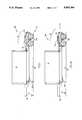
- FIG. 1shows a trailer of the present invention with a 20' container mounted thereon with the rear portion in its normal configuration.
- FIG. 1Ashows the trailer of FIG. 1 with the rear portion in its stored configuration.
- FIG. 2is a detailed side view of the trailer of the present invention.
- FIG. 2Ais a top view of the trailer of FIG. 2 with a number of the trailer's features omitted for descriptive clarity.
- FIG. 3Ais a side view of the rear portion of the trailer of the present invention in its normal configuration.
- FIG. 3Bis a top view of the rear portion shown in FIG. 3A.
- FIG. 4Ais a side view of the rear portion of the trailer of the present invention in its stored configuration.
- FIG. 4Bis a top view of the rear portion shown in FIG. 4A.
- a container transporting trailer 20is shown with a standard 20' container 10 mounted thereon.
- the front and rear of the trailerare referenced in the figures to facilitate the description of relative positions of features of the trailer.
- the trailer 20has a front portion 30, a main portion 50, and a rear portion 70.
- the front portion 30has a kingpin 32 protruding therefrom and attaches to the rear portion of a tractor, not shown in any of the figures.
- the main portion 50 of the trailer 20extends rearward from the forward portion 30.
- the main portion 50is at a level beneath the forward portion 30.
- the container 10is supported by the main portion 50.
- the rear portion 70 of the trailer 20extends rearward from the main portion 50.
- Mounted beneath the rear portion 70 and supporting the rear end of the trailerare wheels 100, attached to a bogie, concealed by the wheels 100 in the figures, the bogie being mounted to the underside of the rear portion 70.
- the trailer 20, as shown in FIGS. 1 and 1A,is supported in a horizontal position at the forward end by landing gear 22 extending vertically from beneath the forward end of the main portion 50.
- the landing gear 22is removed or retracted when the trailer 20 is hitched to a tractor.
- the rear portion 70has an upper surface 76 which is at a level higher than the main portion 50.
- the upper surface 76consists of a non-movable part 74 located toward the rear of the rear portion 70 and a movable segment 72 located toward the front of the rear portion 70.
- the movable segment 72is movable to a position atop the non-movable part 74.
- FIGS. 2 and 2Athe trailer 20 of the present invention is shown without the container loaded thereon, and with the wheels, bogie and landing gear from FIGS. 1 and 1A removed.
- FIGS. 2 and 2Alike features are referenced with the same numeral and these features are equivalent to features similarly referenced in FIGS. 1 and 1A.
- FIG. 2is a side view of the trailer 20 as in FIGS. 1 and 1A.
- FIG. 2Ais a top view of FIG. 2 with one element, described below, omitted.
- the trailer 20is generally a frame-like structure of cross-members.
- Two main support beams 90, 92extend the length of the trailer and are connected by a series of cross-beams 96 which extend across the length of the trailer 20.
- the distance outside to outside of the two main support beams, labelled J in FIG. 2Ais 393/4".
- one cross-beam 90is visible and is shown to have a varying profile.
- the forward portion 30 of the trailer 20is shown in FIGS. 2 and 2A.
- a kingpin 32is shown secured in position by kingpin beam 42 and kingpin angle 44 which extends between main support beams 90, 92. Also extending between main support beams 90, 92 is front rail 48.
- FIG. 2the kingpin 32 is shown and the projections of the beam 42 and angle 44 are shown through the main support beam 90.
- FIG. 2also shows that the forward portion 30 has a horizontal primary section 34 and a downturned gooseneck rear section 36.
- FIGS. 2 and 2A togethershow that the primary section 34 of the forward portion 30 has an upper horizontal plane 38 defined by the upper surface of the main support beams 90, 92.
- the length of the forward portion 30, labelled A in FIGS. 2 and 2A,is approximately 96".
- the main portion 50 of the trailer 20is shown in FIGS. 2 and 2A connected at its forward end to the rear end of the forward portion 30, specifically the gooseneck downturned rear section 36 of the forward portion 30.
- twist lock assemblies 54, 58which include engaging portions which are received in recesses in the four lower corners of a standard 20' container. Twist lock assemblies are old in the intermodal container transporting art and serve to position and intermodal container on the trailer and secure it against horizontal and vertical motion with respect to the trailer.
- a horizontal plane 60is furthermore defined by the upper surfaces of the main support beams 90, 92 of the main portion 50.
- the upper surfaces of support beams 52, 56lie in the horizontal plane 60.
- the engaging portions of twist locks 54, 58lie above plane 60.
- Landing gear mounting fixture 62is shown to extend vertically the width of the main portion 50.
- the width of the main portion 50, labelled F in FIG. 2,is approximately 18".
- the plane 60 of the main portion 50lies below the upper horizontal plane 38 of the forward portion 30.
- the length of the main portion 50is approximately 240" or 20'.
- the main portionis shown to include approximately the space on the trailer occupied by the 20' container.
- the distance of separation between the engaging portions of twist locks 54, 58 along the length of the trailer 20 and across each support member 52, 56is set by the corresponding recesses found in the bottom of a standard 20' container and is approximately 230.5" and 89" respectively.
- the downturned gooseneck rear section 36 of the forward portion 30enables the horizontal plane 60 to lie lower than the upper horizontal plane 38 of the forward portion 38 and, consequently, a container mounted on the main portion 50 rides with its center of gravity lower than if the plane 60 was coextensive with the higher plane 38.
- the downturned rear section 36furthermore allows the main section 34 of the forward portion 30 to lie above and clear the fifth wheel of a tractor when the trailer 20 is mounted on a tractor with kingpin 32 while simultaneously allowing the floor of the container to be positioned at standard loading dock height.
- the difference between the mean height of the forward portion 30 and the mean height of the main portion 50, shown in FIG. 2 as X,is approximately 15".
- the rear portion 70 of the trailer 20is shown in FIGS. 2 and 2A.
- FIG. 2a movable segment 72 of the rear portion 70 and a pivotable mount 78 is shown described more particularly below in the description of FIGS. 3A, 3B, 4A, and 4B.
- the movable segment 72 and pivotable mount 78are omitted from FIG. 2A to facilitate the description of other features.
- pivot support beam 80is located toward the front of rear portion 70, and extends transverse to main support beams 90, 92. Located at each end of the pivot support beam 80 are pivot point fixtures 88. A pair of supplementary support beams 84 also extend transverse to each main support beams 90, 92 without spanning the region between the main support beams 90, 92. The supplementary support beams 84 are located toward the rear of the rear portion 70 with respect to the pivot support beam 88. Further toward the rear of the rear portion 70 is an outrigger support assembly 86 extending transverse to and across main support beams 90, 92.
- pivot support beam 80 and supplementary support beams 84are coplanar with the plane 60 of the main portion 50 and support movable portion 72 when located thereon.
- an elevated non-removable part 74is located to the rear of the rear portion 70 and extends partially above the outrigger support assembly 86.
- the non-movable part 74has a rectangular surface 100 which extends across, as well as along, main support beams 90, 92.
- a segment 102 of surface 100is shown cut away, revealing a series of supporting cross members 98 inside rear portion 74. The outline of the members 98 are shown in broken lines where the surface 100 is not cut away.
- FIG. 2Further shown in FIG. 2 are front, equalizer and rear hangers 76A, 76B, 76C, respectively, to which a wheel bogie is attached to the trailer 20.
- the width of the main support beam 90is reduced at the lower surface by a distance labelled I prior to the front hanger 76A.
- the distance Iis approximately 6".
- the length of the rear portion 70, labelled Cis approximately 132".
- FIGS. 3A, 3B, 4A, and 4Bshow a more detailed side and top view of the rear portion 70 of the trailer 20 of the prior figures.
- the wheels 100are shown mounted through a bogie, not shown in FIGS. 3A and 3B, to hangers 76A, 76B, 76C.
- FIGS. 3A, 3B, 4A, and 4Bare also shown in FIGS. 3A, 3B, 4A, and 4B and described above with respect to FIGS. 2 and 2A.
- the movable part 72 and related features, mentioned above with respect to FIG. 2 which were not described there,are shown in FIGS. 3A, 3B, 4A, and 4B are now described in detail.
- FIGS. 3A and 3Billustrate the top and side views of rear portion 70, with movable segment 72 shown in its normal position.
- the upper surface of movable segment 72lies in a plane 100 with the upper surface of non-movable part 74.
- the width of the movable segment 72 across the main support beams 90, 92is approximately equal to the width of the non-movable part 74.
- the plane 100 formed by the movable segment 72 and the non-movable part 74forms a platform for loading and unloading a container from or to a loading dock adjacent the rear of the truck.
- plane 120will be substantially co-extensive with the floor of a container loaded on main portion 50. Loading and unloading a container on main portion 50 is facilitated since the container floor, plane 120 and a loading dock against which the trailer is backed all lie in one plane.
- a dolly or hand truckmay therefore be wheeled in one plane between the container and the loading dock.
- pivot arms 78are located on opposite sides of movable segment 72 and pivotably secured to pivot point fixtures 88 at pivot points 106.
- Mounting pins 104, 108are secured to movable segment 72 and interface with grooves 110, shown in FIGS. 3A and 3B in dashed lines, in pivot arms 78.
- FIGS. 4A and 4Bthe trailer is shown with the movable segment 72 in its temporary position atop the non-movable part 74.
- the pivot arms 78are shown most clearly in FIG. 4A to be pivoted around pivot points 106.
- Mounting pins 108are located at the rear end of grooves 110 thereby preventing further rearward movement of movable segment 72. Gathering plates 102, extending vertically from the non-movable part 74 on each side of the movable segment 72 prevent any horizontal movement of the movable segment 72 across the length of the trailer.
- a removable segmentcould also be used as segment 72, and the phase movable segment is intended to include both movable and removable segments.
Landscapes
- Engineering & Computer Science (AREA)
- Transportation (AREA)
- Mechanical Engineering (AREA)
- Chemical & Material Sciences (AREA)
- Combustion & Propulsion (AREA)
- Handcart (AREA)
Abstract
Description
Claims (31)
Priority Applications (1)
| Application Number | Priority Date | Filing Date | Title |
|---|---|---|---|
| US07/533,681US5082304A (en) | 1990-06-05 | 1990-06-05 | Twenty foot container transporter |
Applications Claiming Priority (1)
| Application Number | Priority Date | Filing Date | Title |
|---|---|---|---|
| US07/533,681US5082304A (en) | 1990-06-05 | 1990-06-05 | Twenty foot container transporter |
Publications (1)
| Publication Number | Publication Date |
|---|---|
| US5082304Atrue US5082304A (en) | 1992-01-21 |
Family
ID=24127006
Family Applications (1)
| Application Number | Title | Priority Date | Filing Date |
|---|---|---|---|
| US07/533,681Expired - Fee RelatedUS5082304A (en) | 1990-06-05 | 1990-06-05 | Twenty foot container transporter |
Country Status (1)
| Country | Link |
|---|---|
| US (1) | US5082304A (en) |
Cited By (28)
| Publication number | Priority date | Publication date | Assignee | Title |
|---|---|---|---|---|
| WO1993018934A1 (en)* | 1992-03-25 | 1993-09-30 | The Secretary Of State For Defence In Her Britannic Majesty's Government | Load carrying system |
| US6309153B1 (en) | 1997-10-30 | 2001-10-30 | Accurate Industries, Inc. | Intermodal transfer trailer |
| WO2006074923A1 (en)* | 2005-01-14 | 2006-07-20 | Ab Skf | Semi-trailer and truck |
| US20060182580A1 (en)* | 2004-12-15 | 2006-08-17 | Petersen Lewis H | Truck container transport/storage system and method |
| US20100133781A1 (en)* | 2007-12-21 | 2010-06-03 | Denis Gosselin | Flatbed trailer having an extendable configuration and an alternate configuration |
| CN101190692B (en)* | 2006-11-27 | 2010-10-06 | 中国国际海运集装箱(集团)股份有限公司 | Self-discharging semitrailer vehicle frame |
| US20100320727A1 (en)* | 2009-06-18 | 2010-12-23 | Kenneth Haut | Intermodal tank transport system, components, and methods |
| US20100320708A1 (en)* | 2009-03-03 | 2010-12-23 | Green Horizon Manufacturing Llc | System and method of transporting and positioning a deployable prefabricated structure |
| US9669993B2 (en) | 2012-07-23 | 2017-06-06 | Oren Technologies, Llc | Proppant discharge system and a container for use in such a proppant discharge system |
| US9670752B2 (en) | 2014-09-15 | 2017-06-06 | Oren Technologies, Llc | System and method for delivering proppant to a blender |
| US9676554B2 (en) | 2014-09-15 | 2017-06-13 | Oren Technologies, Llc | System and method for delivering proppant to a blender |
| US9682815B2 (en) | 2011-12-21 | 2017-06-20 | Oren Technologies, Llc | Methods of storing and moving proppant at location adjacent rail line |
| US9718610B2 (en) | 2012-07-23 | 2017-08-01 | Oren Technologies, Llc | Proppant discharge system having a container and the process for providing proppant to a well site |
| USRE46531E1 (en) | 2012-11-02 | 2017-09-05 | Oren Technologies, Llc | Proppant vessel base |
| US9758081B2 (en) | 2012-07-23 | 2017-09-12 | Oren Technologies, Llc | Trailer-mounted proppant delivery system |
| USRE46576E1 (en) | 2013-05-17 | 2017-10-24 | Oren Technologies, Llc | Trailer for proppant containers |
| US9796319B1 (en)* | 2013-04-01 | 2017-10-24 | Oren Technologies, Llc | Trailer assembly for transport of containers of proppant material |
| USRE46590E1 (en) | 2013-05-17 | 2017-10-31 | Oren Technologies, Llc | Train car for proppant containers |
| US9809381B2 (en) | 2012-07-23 | 2017-11-07 | Oren Technologies, Llc | Apparatus for the transport and storage of proppant |
| USRE46613E1 (en) | 2012-11-02 | 2017-11-28 | Oren Technologies, Llc | Proppant vessel |
| US9840366B2 (en) | 2014-06-13 | 2017-12-12 | Oren Technologies, Llc | Cradle for proppant container having tapered box guides |
| US9845210B2 (en) | 2016-01-06 | 2017-12-19 | Oren Technologies, Llc | Conveyor with integrated dust collector system |
| USRE46645E1 (en) | 2013-04-05 | 2017-12-26 | Oren Technologies, Llc | Trailer for proppant containers |
| US9862551B2 (en) | 2012-07-23 | 2018-01-09 | Oren Technologies, Llc | Methods and systems to transfer proppant for fracking with reduced risk of production and release of silica dust at a well site |
| USRE47162E1 (en) | 2012-11-02 | 2018-12-18 | Oren Technologies, Llc | Proppant vessel |
| CN109153300A (en)* | 2016-06-03 | 2019-01-04 | 奥伦技术有限责任公司 | The trailer components of container and associated method for transfer of support agent material |
| USD847489S1 (en) | 2012-09-24 | 2019-05-07 | Sandbox Logistics, Llc | Proppant container |
| US11873160B1 (en) | 2014-07-24 | 2024-01-16 | Sandbox Enterprises, Llc | Systems and methods for remotely controlling proppant discharge system |
Citations (4)
| Publication number | Priority date | Publication date | Assignee | Title |
|---|---|---|---|---|
| US3467408A (en)* | 1967-04-20 | 1969-09-16 | Emil Louis Regalia | Heavy duty truck trailer |
| US3508762A (en)* | 1968-03-22 | 1970-04-28 | Clark Equipment Co | Container chassis |
| US4580805A (en)* | 1984-11-23 | 1986-04-08 | Titan, Inc. | Extendable container chassis for trucks |
| US4836735A (en)* | 1988-03-11 | 1989-06-06 | Xtra Corporation | Load positioning container chassis |
- 1990
- 1990-06-05USUS07/533,681patent/US5082304A/ennot_activeExpired - Fee Related
Patent Citations (4)
| Publication number | Priority date | Publication date | Assignee | Title |
|---|---|---|---|---|
| US3467408A (en)* | 1967-04-20 | 1969-09-16 | Emil Louis Regalia | Heavy duty truck trailer |
| US3508762A (en)* | 1968-03-22 | 1970-04-28 | Clark Equipment Co | Container chassis |
| US4580805A (en)* | 1984-11-23 | 1986-04-08 | Titan, Inc. | Extendable container chassis for trucks |
| US4836735A (en)* | 1988-03-11 | 1989-06-06 | Xtra Corporation | Load positioning container chassis |
Cited By (76)
| Publication number | Priority date | Publication date | Assignee | Title |
|---|---|---|---|---|
| WO1993018934A1 (en)* | 1992-03-25 | 1993-09-30 | The Secretary Of State For Defence In Her Britannic Majesty's Government | Load carrying system |
| US6309153B1 (en) | 1997-10-30 | 2001-10-30 | Accurate Industries, Inc. | Intermodal transfer trailer |
| US20060182580A1 (en)* | 2004-12-15 | 2006-08-17 | Petersen Lewis H | Truck container transport/storage system and method |
| WO2006074923A1 (en)* | 2005-01-14 | 2006-07-20 | Ab Skf | Semi-trailer and truck |
| CN101190692B (en)* | 2006-11-27 | 2010-10-06 | 中国国际海运集装箱(集团)股份有限公司 | Self-discharging semitrailer vehicle frame |
| US20110140473A1 (en)* | 2007-12-21 | 2011-06-16 | Mac Trailer Manufacturing, Inc. | Flatbed trailer having an extendable configuration and an alternate configuration |
| US8070214B2 (en) | 2007-12-21 | 2011-12-06 | Mac Trailer Manufacturing, Inc. | Flatbed trailer having an extendable configuration and an alternate configuration |
| US20100133781A1 (en)* | 2007-12-21 | 2010-06-03 | Denis Gosselin | Flatbed trailer having an extendable configuration and an alternate configuration |
| US7909387B2 (en)* | 2007-12-21 | 2011-03-22 | Mac Trailer Manufacturing, Inc. | Flatbed trailer having an extendable configuration and an alternate configuration |
| US8191957B2 (en) | 2007-12-21 | 2012-06-05 | Mac Trailer Manufacturing, Inc. | Flatbed trailer having an extendable configuration and an alternate configuration |
| US20100320708A1 (en)* | 2009-03-03 | 2010-12-23 | Green Horizon Manufacturing Llc | System and method of transporting and positioning a deployable prefabricated structure |
| USD653587S1 (en) | 2009-06-18 | 2012-02-07 | International Transport Equipment Corporation | Intermodal tank container |
| US10518690B2 (en) | 2009-06-18 | 2019-12-31 | International Transport Equipment Company | Intermodal tank transport system, components, and methods |
| US20100320727A1 (en)* | 2009-06-18 | 2010-12-23 | Kenneth Haut | Intermodal tank transport system, components, and methods |
| CN102803054A (en)* | 2009-06-18 | 2012-11-28 | 国际运输设备有限公司 | Intermodal tank container transportation system, assembly and method |
| US8827313B2 (en) | 2009-06-18 | 2014-09-09 | International Transport Equipment Corporation | Intermodal tank transport system, components, and methods |
| WO2010147672A1 (en)* | 2009-06-18 | 2010-12-23 | International Transportation Equipment Corporation | Intermodal tank transport system, components, and methods |
| US10562702B2 (en) | 2011-09-23 | 2020-02-18 | Sandbox Logistics, Llc | Systems and methods for bulk material storage and/or transport |
| US10538381B2 (en) | 2011-09-23 | 2020-01-21 | Sandbox Logistics, Llc | Systems and methods for bulk material storage and/or transport |
| US10703587B2 (en) | 2011-12-21 | 2020-07-07 | Oren Technologies, Llc | Method of delivering, transporting, and storing proppant for delivery and use at a well site |
| US9682815B2 (en) | 2011-12-21 | 2017-06-20 | Oren Technologies, Llc | Methods of storing and moving proppant at location adjacent rail line |
| US9914602B2 (en) | 2011-12-21 | 2018-03-13 | Oren Technologies, Llc | Methods of storing and moving proppant at location adjacent rail line |
| US9932181B2 (en) | 2011-12-21 | 2018-04-03 | Oren Technologies, Llc | Method of delivering, transporting, and storing proppant for delivery and use at a well site |
| US9718610B2 (en) | 2012-07-23 | 2017-08-01 | Oren Technologies, Llc | Proppant discharge system having a container and the process for providing proppant to a well site |
| US9815620B2 (en) | 2012-07-23 | 2017-11-14 | Oren Technologies, Llc | Proppant discharge system and a container for use in such a proppant discharge system |
| US9725233B2 (en) | 2012-07-23 | 2017-08-08 | Oren Technologies, Llc | Proppant discharge system and a container for use in such a proppant discharge system |
| US9738439B2 (en) | 2012-07-23 | 2017-08-22 | Oren Technologies, Llc | Proppant discharge system and a container for use in such a proppant discharge system |
| US10745194B2 (en) | 2012-07-23 | 2020-08-18 | Oren Technologies, Llc | Cradle for proppant container having tapered box guides and associated methods |
| US9758081B2 (en) | 2012-07-23 | 2017-09-12 | Oren Technologies, Llc | Trailer-mounted proppant delivery system |
| US9771224B2 (en) | 2012-07-23 | 2017-09-26 | Oren Technologies, Llc | Support apparatus for moving proppant from a container in a proppant discharge system |
| US9718609B2 (en) | 2012-07-23 | 2017-08-01 | Oren Technologies, Llc | Proppant discharge system and a container for use in such a proppant discharge system |
| US10662006B2 (en) | 2012-07-23 | 2020-05-26 | Oren Technologies, Llc | Proppant discharge system having a container and the process for providing proppant to a well site |
| US10661981B2 (en) | 2012-07-23 | 2020-05-26 | Oren Technologies, Llc | Proppant discharge system and a container for use in such a proppant discharge system |
| US9809381B2 (en) | 2012-07-23 | 2017-11-07 | Oren Technologies, Llc | Apparatus for the transport and storage of proppant |
| US9725234B2 (en) | 2012-07-23 | 2017-08-08 | Oren Technologies, Llc | Proppant discharge system and a container for use in such a proppant discharge system |
| US10661980B2 (en) | 2012-07-23 | 2020-05-26 | Oren Technologies, Llc | Method of delivering, storing, unloading, and using proppant at a well site |
| US9834373B2 (en) | 2012-07-23 | 2017-12-05 | Oren Technologies, Llc | Proppant discharge system and a container for use in such a proppant discharge system |
| US10569953B2 (en) | 2012-07-23 | 2020-02-25 | Oren Technologies, Llc | Proppant discharge system and a container for use in such a proppant discharge system |
| US9969564B2 (en) | 2012-07-23 | 2018-05-15 | Oren Technologies, Llc | Methods and systems to transfer proppant for fracking with reduced risk of production and release of silica dust at a well site |
| US9701463B2 (en) | 2012-07-23 | 2017-07-11 | Oren Technologies, Llc | Method of delivering, storing, unloading, and using proppant at a well site |
| US9862551B2 (en) | 2012-07-23 | 2018-01-09 | Oren Technologies, Llc | Methods and systems to transfer proppant for fracking with reduced risk of production and release of silica dust at a well site |
| US9694970B2 (en) | 2012-07-23 | 2017-07-04 | Oren Technologies, Llc | Proppant discharge system and a container for use in such a proppant discharge system |
| US10464741B2 (en) | 2012-07-23 | 2019-11-05 | Oren Technologies, Llc | Proppant discharge system and a container for use in such a proppant discharge system |
| US10787312B2 (en) | 2012-07-23 | 2020-09-29 | Oren Technologies, Llc | Apparatus for the transport and storage of proppant |
| US10814767B2 (en) | 2012-07-23 | 2020-10-27 | Oren Technologies, Llc | Trailer-mounted proppant delivery system |
| US9669993B2 (en) | 2012-07-23 | 2017-06-06 | Oren Technologies, Llc | Proppant discharge system and a container for use in such a proppant discharge system |
| US10239436B2 (en) | 2012-07-23 | 2019-03-26 | Oren Technologies, Llc | Trailer-mounted proppant delivery system |
| USD847489S1 (en) | 2012-09-24 | 2019-05-07 | Sandbox Logistics, Llc | Proppant container |
| USRE46613E1 (en) | 2012-11-02 | 2017-11-28 | Oren Technologies, Llc | Proppant vessel |
| USRE47162E1 (en) | 2012-11-02 | 2018-12-18 | Oren Technologies, Llc | Proppant vessel |
| USRE46531E1 (en) | 2012-11-02 | 2017-09-05 | Oren Technologies, Llc | Proppant vessel base |
| US10059246B1 (en) | 2013-04-01 | 2018-08-28 | Oren Technologies, Llc | Trailer assembly for transport of containers of proppant material |
| US9796319B1 (en)* | 2013-04-01 | 2017-10-24 | Oren Technologies, Llc | Trailer assembly for transport of containers of proppant material |
| USRE46645E1 (en) | 2013-04-05 | 2017-12-26 | Oren Technologies, Llc | Trailer for proppant containers |
| USRE46576E1 (en) | 2013-05-17 | 2017-10-24 | Oren Technologies, Llc | Trailer for proppant containers |
| USRE46590E1 (en) | 2013-05-17 | 2017-10-31 | Oren Technologies, Llc | Train car for proppant containers |
| US9840366B2 (en) | 2014-06-13 | 2017-12-12 | Oren Technologies, Llc | Cradle for proppant container having tapered box guides |
| US11873160B1 (en) | 2014-07-24 | 2024-01-16 | Sandbox Enterprises, Llc | Systems and methods for remotely controlling proppant discharge system |
| US10179703B2 (en) | 2014-09-15 | 2019-01-15 | Oren Technologies, Llc | System and method for delivering proppant to a blender |
| US10399789B2 (en) | 2014-09-15 | 2019-09-03 | Oren Technologies, Llc | System and method for delivering proppant to a blender |
| US9988215B2 (en) | 2014-09-15 | 2018-06-05 | Oren Technologies, Llc | System and method for delivering proppant to a blender |
| US9676554B2 (en) | 2014-09-15 | 2017-06-13 | Oren Technologies, Llc | System and method for delivering proppant to a blender |
| US9670752B2 (en) | 2014-09-15 | 2017-06-06 | Oren Technologies, Llc | System and method for delivering proppant to a blender |
| US9963308B2 (en) | 2016-01-06 | 2018-05-08 | Oren Technologies, Llc | Conveyor with integrated dust collector system |
| US9845210B2 (en) | 2016-01-06 | 2017-12-19 | Oren Technologies, Llc | Conveyor with integrated dust collector system |
| US9868598B2 (en) | 2016-01-06 | 2018-01-16 | Oren Technologies, Llc | Conveyor with integrated dust collector system |
| US10676296B2 (en) | 2016-01-06 | 2020-06-09 | Oren Technologies, Llc | Conveyor with integrated dust collector system |
| US9902576B1 (en)* | 2016-01-06 | 2018-02-27 | Oren Technologies, Llc | Conveyor with integrated dust collector system |
| US9932183B2 (en) | 2016-01-06 | 2018-04-03 | Oren Technologies, Llc | Conveyor with integrated dust collector system |
| US10065816B2 (en) | 2016-01-06 | 2018-09-04 | Oren Technologies, Llc | Conveyor with integrated dust collector system |
| US10926967B2 (en) | 2016-01-06 | 2021-02-23 | Sandbox Enterprises, Llc | Conveyor with integrated dust collector system |
| US11414282B2 (en) | 2016-01-06 | 2022-08-16 | Sandbox Enterprises, Llc | System for conveying proppant to a fracking site hopper |
| US10035668B2 (en) | 2016-01-06 | 2018-07-31 | Oren Technologies, Llc | Conveyor with integrated dust collector system |
| EP3463937A4 (en)* | 2016-06-03 | 2020-03-25 | Oren Technologies, LLC | TRAILER ARRANGEMENT FOR THE TRANSPORT OF SUPPORT CONTAINERS AND RELATED METHODS |
| US10518828B2 (en) | 2016-06-03 | 2019-12-31 | Oren Technologies, Llc | Trailer assembly for transport of containers of proppant material |
| CN109153300A (en)* | 2016-06-03 | 2019-01-04 | 奥伦技术有限责任公司 | The trailer components of container and associated method for transfer of support agent material |
Similar Documents
| Publication | Publication Date | Title |
|---|---|---|
| US5082304A (en) | Twenty foot container transporter | |
| US4759668A (en) | Method and apparatus to enhance intermodal containers for cargo transport | |
| US4568235A (en) | Low angle tilt trailer | |
| US4881859A (en) | Trailer for selectively transporting vehicles and general freight | |
| EP0371050B1 (en) | Arrangement for a closeable cargo holder of the container type | |
| US4179997A (en) | Rail-highway intermodal freight carrier transport system | |
| US4635742A (en) | Extendable chassis | |
| US5507514A (en) | Dockable container chassis | |
| US20130058745A1 (en) | Level lift trailer with detachable cargo bed | |
| US5678978A (en) | Apparatus for a tiltable rolloff trailer having a displacable frame | |
| JP5728079B2 (en) | Convertible trailer | |
| CA2166757C (en) | Container support pedestal | |
| CN106573567A (en) | Individual, universal, removable, load-bearing pallet for car-carrying vehicle | |
| US4475740A (en) | Articulated truck/trailer combination | |
| US5857825A (en) | Trailer operable as ramp for rear loading truck | |
| US4685720A (en) | Semitrailer and method of loading the same | |
| JPS6253379B2 (en) | ||
| US3070041A (en) | Highway-railway transportation system and apparatus | |
| US4948310A (en) | Rail vehicle for transporting road semi-trailers | |
| US4496187A (en) | Trailer construction | |
| US4606090A (en) | Auxiliary loading dock ramp | |
| US5127781A (en) | Chassis conversion saddle | |
| US5040814A (en) | Road transport unit with demountable body | |
| US6109845A (en) | Trailer recovery vehicle | |
| EP1028881B1 (en) | Fifth wheel arrangement for rail freight vehicle |
Legal Events
| Date | Code | Title | Description |
|---|---|---|---|
| AS | Assignment | Owner name:SEA-LAND SERVICE INC., NEW JERSEY Free format text:ASSIGNMENT OF ASSIGNORS INTEREST.;ASSIGNORS:PRELLER, ROBERT E.;MIEDAMA, DONALD L.;REEL/FRAME:005343/0557 Effective date:19900516 | |
| CC | Certificate of correction | ||
| FEPP | Fee payment procedure | Free format text:PAYOR NUMBER ASSIGNED (ORIGINAL EVENT CODE: ASPN); ENTITY STATUS OF PATENT OWNER: LARGE ENTITY | |
| FPAY | Fee payment | Year of fee payment:4 | |
| FPAY | Fee payment | Year of fee payment:8 | |
| AS | Assignment | Owner name:AKTIESELSKABET DAMPSKIBSSELSKABET SVENDBORG, DENMA Free format text:ASSIGNMENT OF ASSIGNORS INTEREST;ASSIGNOR:SEA-LAND SERVICE, INC.;REEL/FRAME:010506/0412 Effective date:19991210 Owner name:DAMPSKIBSSELSKABET AF 1912, AKTIESELKAB, DENMARK Free format text:ASSIGNMENT OF ASSIGNORS INTEREST;ASSIGNOR:SEA-LAND SERVICE, INC.;REEL/FRAME:010506/0412 Effective date:19991210 | |
| REMI | Maintenance fee reminder mailed | ||
| LAPS | Lapse for failure to pay maintenance fees | ||
| STCH | Information on status: patent discontinuation | Free format text:PATENT EXPIRED DUE TO NONPAYMENT OF MAINTENANCE FEES UNDER 37 CFR 1.362 | |
| FP | Lapsed due to failure to pay maintenance fee | Effective date:20040121 |