US5081639A - Laser diode assembly including a cylindrical lens - Google Patents
Laser diode assembly including a cylindrical lensDownload PDFInfo
- Publication number
- US5081639A US5081639AUS07/591,409US59140990AUS5081639AUS 5081639 AUS5081639 AUS 5081639AUS 59140990 AUS59140990 AUS 59140990AUS 5081639 AUS5081639 AUS 5081639A
- Authority
- US
- United States
- Prior art keywords
- cylindrical
- laser
- laser diode
- axis
- lens
- Prior art date
- Legal status (The legal status is an assumption and is not a legal conclusion. Google has not performed a legal analysis and makes no representation as to the accuracy of the status listed.)
- Expired - Lifetime
Links
- 230000003287optical effectEffects0.000claimsabstractdescription29
- 239000000463materialSubstances0.000claimsdescription21
- 239000013307optical fiberSubstances0.000claimsdescription10
- 230000005855radiationEffects0.000claimsdescription7
- 239000004568cementSubstances0.000claimsdescription6
- 239000011521glassSubstances0.000abstractdescription36
- 238000000034methodMethods0.000abstractdescription27
- 239000000835fiberSubstances0.000abstractdescription10
- 238000009826distributionMethods0.000abstractdescription6
- 238000005498polishingMethods0.000abstractdescription6
- 230000004075alterationEffects0.000description12
- 238000004519manufacturing processMethods0.000description7
- 230000001419dependent effectEffects0.000description4
- 238000005086pumpingMethods0.000description4
- 230000008878couplingEffects0.000description3
- 238000010168coupling processMethods0.000description3
- 238000005859coupling reactionMethods0.000description3
- 230000000694effectsEffects0.000description3
- 238000000465mouldingMethods0.000description3
- 239000006089photosensitive glassSubstances0.000description3
- 239000007787solidSubstances0.000description3
- 238000004458analytical methodMethods0.000description2
- 230000007547defectEffects0.000description2
- 206010010071ComaDiseases0.000description1
- 238000000862absorption spectrumMethods0.000description1
- 238000004026adhesive bondingMethods0.000description1
- 230000000712assemblyEffects0.000description1
- 238000000429assemblyMethods0.000description1
- 230000015572biosynthetic processEffects0.000description1
- 238000006243chemical reactionMethods0.000description1
- 230000006835compressionEffects0.000description1
- 238000007906compressionMethods0.000description1
- 238000010586diagramMethods0.000description1
- 238000009792diffusion processMethods0.000description1
- 230000002500effect on skinEffects0.000description1
- 238000005516engineering processMethods0.000description1
- 239000012467final productSubstances0.000description1
- 238000003384imaging methodMethods0.000description1
- 238000007654immersionMethods0.000description1
- 238000001459lithographyMethods0.000description1
- 239000006060molten glassSubstances0.000description1
- 230000001902propagating effectEffects0.000description1
- 230000000717retained effectEffects0.000description1
- 239000004065semiconductorSubstances0.000description1
Images


Classifications
- C—CHEMISTRY; METALLURGY
- C03—GLASS; MINERAL OR SLAG WOOL
- C03B—MANUFACTURE, SHAPING, OR SUPPLEMENTARY PROCESSES
- C03B37/00—Manufacture or treatment of flakes, fibres, or filaments from softened glass, minerals, or slags
- C03B37/01—Manufacture of glass fibres or filaments
- C03B37/02—Manufacture of glass fibres or filaments by drawing or extruding, e.g. direct drawing of molten glass from nozzles; Cooling fins therefor
- C03B37/025—Manufacture of glass fibres or filaments by drawing or extruding, e.g. direct drawing of molten glass from nozzles; Cooling fins therefor from reheated softened tubes, rods, fibres or filaments, e.g. drawing fibres from preforms
- C03B37/027—Fibres composed of different sorts of glass, e.g. glass optical fibres
- G—PHYSICS
- G02—OPTICS
- G02B—OPTICAL ELEMENTS, SYSTEMS OR APPARATUS
- G02B6/00—Light guides; Structural details of arrangements comprising light guides and other optical elements, e.g. couplings
- G02B6/24—Coupling light guides
- G02B6/26—Optical coupling means
- G02B6/32—Optical coupling means having lens focusing means positioned between opposed fibre ends
- G—PHYSICS
- G02—OPTICS
- G02B—OPTICAL ELEMENTS, SYSTEMS OR APPARATUS
- G02B6/00—Light guides; Structural details of arrangements comprising light guides and other optical elements, e.g. couplings
- G02B6/24—Coupling light guides
- G02B6/42—Coupling light guides with opto-electronic elements
- G02B6/4201—Packages, e.g. shape, construction, internal or external details
- G02B6/4204—Packages, e.g. shape, construction, internal or external details the coupling comprising intermediate optical elements, e.g. lenses, holograms
- G02B6/4206—Optical features
- G—PHYSICS
- G02—OPTICS
- G02B—OPTICAL ELEMENTS, SYSTEMS OR APPARATUS
- G02B6/00—Light guides; Structural details of arrangements comprising light guides and other optical elements, e.g. couplings
- G02B6/24—Coupling light guides
- G02B6/42—Coupling light guides with opto-electronic elements
- G02B6/4201—Packages, e.g. shape, construction, internal or external details
- G02B6/4249—Packages, e.g. shape, construction, internal or external details comprising arrays of active devices and fibres
- G02B6/425—Optical features
- H—ELECTRICITY
- H01—ELECTRIC ELEMENTS
- H01S—DEVICES USING THE PROCESS OF LIGHT AMPLIFICATION BY STIMULATED EMISSION OF RADIATION [LASER] TO AMPLIFY OR GENERATE LIGHT; DEVICES USING STIMULATED EMISSION OF ELECTROMAGNETIC RADIATION IN WAVE RANGES OTHER THAN OPTICAL
- H01S3/00—Lasers, i.e. devices using stimulated emission of electromagnetic radiation in the infrared, visible or ultraviolet wave range
- H01S3/005—Optical devices external to the laser cavity, specially adapted for lasers, e.g. for homogenisation of the beam or for manipulating laser pulses, e.g. pulse shaping
- H—ELECTRICITY
- H01—ELECTRIC ELEMENTS
- H01S—DEVICES USING THE PROCESS OF LIGHT AMPLIFICATION BY STIMULATED EMISSION OF RADIATION [LASER] TO AMPLIFY OR GENERATE LIGHT; DEVICES USING STIMULATED EMISSION OF ELECTROMAGNETIC RADIATION IN WAVE RANGES OTHER THAN OPTICAL
- H01S5/00—Semiconductor lasers
- H01S5/02—Structural details or components not essential to laser action
- H01S5/026—Monolithically integrated components, e.g. waveguides, monitoring photo-detectors, drivers
- C—CHEMISTRY; METALLURGY
- C03—GLASS; MINERAL OR SLAG WOOL
- C03B—MANUFACTURE, SHAPING, OR SUPPLEMENTARY PROCESSES
- C03B2203/00—Fibre product details, e.g. structure, shape
- C03B2203/02—External structure or shape details
- C03B2203/04—Polygonal outer cross-section, e.g. triangular, square
- H—ELECTRICITY
- H01—ELECTRIC ELEMENTS
- H01S—DEVICES USING THE PROCESS OF LIGHT AMPLIFICATION BY STIMULATED EMISSION OF RADIATION [LASER] TO AMPLIFY OR GENERATE LIGHT; DEVICES USING STIMULATED EMISSION OF ELECTROMAGNETIC RADIATION IN WAVE RANGES OTHER THAN OPTICAL
- H01S5/00—Semiconductor lasers
- H01S5/005—Optical components external to the laser cavity, specially adapted therefor, e.g. for homogenisation or merging of the beams or for manipulating laser pulses, e.g. pulse shaping
- H—ELECTRICITY
- H01—ELECTRIC ELEMENTS
- H01S—DEVICES USING THE PROCESS OF LIGHT AMPLIFICATION BY STIMULATED EMISSION OF RADIATION [LASER] TO AMPLIFY OR GENERATE LIGHT; DEVICES USING STIMULATED EMISSION OF ELECTROMAGNETIC RADIATION IN WAVE RANGES OTHER THAN OPTICAL
- H01S5/00—Semiconductor lasers
- H01S5/40—Arrangement of two or more semiconductor lasers, not provided for in groups H01S5/02 - H01S5/30
- H01S5/4025—Array arrangements, e.g. constituted by discrete laser diodes or laser bar
Definitions
- the present inventionrelates to microlenses. More specifically, the present invention relates to cylindrical microlenses for use with laser diodes and integrated optics.
- a lensis an optical element that can focus or de-focus light.
- the most familiar types of lensesare circular; for example, a circular converging lens focuses light to a point. Such lenses are useful for many applications, such as imaging and photography.
- the familiar circular lenshas a shape that is symmetrical around the optical axis.
- a cylindrical converging lensfocuses light along a line, typically termed the "line focus".
- the typical cylindrical lensis shaped symmetrically around a principal axis, which is orthogonal to the optical axis.
- a cylindrical glass lensmay have the shape of a cylinder, with circular dimensions around a central axis. Light is made incident on a first curved surface of the cylinder, and exits from the other, second curved side of the cylinder.
- cylindrical lensesmay require specific shapes quite different from the circular curve of the previous example.
- the required shapemight be flat or it could be some other non-circular curve such as elliptical or hyperbolic.
- cylindrical lensesmay be formed with a variety of curved surfaces. The exact shape chosen is highly dependent upon the application.
- the circular and flat shapesare easy to manufacture, and are common in cylindrical lenses. However, these shapes have disadvantages, such as spherical aberration which causes mis-focusing of marginal rays.
- Spherical aberrationcan be substantially reduced by careful design and manufacture of the shape of the input and output surfaces.
- Other types of aberrations, such as comacan also be reduced by careful lens design and manufacture. If a lens is designed to substantially reduce all significant aberrations, then it may be termed "diffraction-limited".
- a diffraction-limited lensmakes efficient use of the light it receives by providing the highest intensity at the focus.
- a figure of importance for any lensis its numerical aperture. Quantitatively, the numerical aperture is given by:
- ⁇is the angular semi-aperture of the lens and n is the refractive index of the medium in which the light is focused.
- the numerical apertureis a measure of the resolving and light gathering power of a lens. The numerical aperture is affected by the size of the aperture and its focal length. If the numerical aperture of a lens is greater than the numerical aperture of the source that the lens is collimating, then all light from the source can be collimated. On the other hand, if the numerical aperture of the lens is less than that of the source, then some of the light emitted from the source cannot be collimated, and may be lost or directed away. If a lens has a high numerical aperture, then it may be termed "fast".
- a maskis first deposited on the glass, and the material outside the desired lens is exposed to light.
- the exposed materialexpands its volume, and the unexposed lens region is compressed. The compression causes the lens region to bulge, forming a simple lens.
- Graded index microlensesare formed by diffusing index-changing material into glass. The diffusion process yields an index of refraction that varies smoothly from the lens center to the edge. The graded index focuses the light much as a conventional lens does.
- the surface of a glass plateis etched according to a pattern generated by computer.
- the etched surfaceis designed to diffract light to a focal point, so that it performs like a conventional lens.
- Cylindrical microlenses fabricated from photosensitive glass and graded index planar microlensescan be produced inexpensively in quantity, but these single optical elements are limited in speed to numerical apertures of 0.25 to 0.32, and furthermore they cannot be corrected for spherical aberration.
- Diffractive optic kinoformscan be corrected for aberrations, but efficient kinoform lenses with numerical apertures approaching 0.5 require the use of sub-quarter-micron lithography, which is currently beyond the state of the art.
- Optical fibers with a circular cross-sectionhave been used for cylindrical lenses.
- Optical fiberis inexpensive and readily available.
- circular optical fibersare not corrected for spherical aberration; i.e., such optical fibers are not diffraction limited.
- the lenscould be designed with any of a variety of input and output surfaces. Such a lens could be designed to correct for spherical aberration, for example.
- Cylindrical microlensescould be utilized for integrated optics, and for focusing of laser diode bars. In integrated optics, a carefully designed cylindrical microlens could efficiently and conveniently couple light into or out of narrow waveguides, or any narrow slit.
- cylindrical microlensescould form a part of a low cost, high efficiency laser diode system for pumping higher power lasers.
- high power lasershave a gain material that is optically pumped by high intensity flashlamps that are inefficient and have high voltage requirements.
- laser diodesare more efficient and long-lived, and require low voltage electrical sources rather than the high voltage sources used to pump flashlamps. Replacement of flashlamps with laser diodes would increase efficiency of a high power laser by reducing electrical costs, and such replacement would also increase reliability and longevity.
- a laser diodeemits substantially a single wavelength, which can be chosen to match the absorption spectra of the gain material for high efficiency conversion from pump energy to stored energy in the gain material.
- the pumping energycan be supplied from an array of laser diodes, which may comprise a number of laser diode bars closely stacked. In such an arrangement, it is useful if substantially all the light emitted by the laser diode bars is delivered to the solid state gain material. For this purpose, it is advantageous that the diode laser beams from each individual laser diode bar be directed to the gain material. Any portion of the beam not directed to the gain material may be lost energy.
- the laser diode barshave a numerical aperture of about 0.5, and therefore a suitable cylindrical lens should have a 0.5 numerical aperture or higher, a figure that is beyond the state of the current technology.
- a diffraction limited cylindrical lens having a numerical aperture greater than 0.5could collimate a beam from a laser diode.
- a collimated beamis one that is neither converging nor diverging; i.e., the rays within the beam are travelling substantially parallel.
- a focused beamconverges to the point of focus, and then diverges to infinity.
- the laser diode baris an efficient source of laser radiation, however the highly divergent beam emitted from the laser diode presents problems in applications.
- the divergence of the laser diode's beamis caused by its exit aperture, which is very narrow along one axis (the "fast" axis), and much wider along the other (perpendicular) axis.
- the cross-section of the beam emitted along the fast axis(the narrow aperture) is highly divergent due to diffraction effects.
- the wider apertureemits a beam cross-section that diverges only slightly.
- Conventional optical fibers with a circular cross-sectionhave been used to collimate the beam from a laser diode bar.
- the circular fiberis not diffraction limited; the circular shape has the disadvantage of spherical aberration and thus a large portion of the light focused by such a fiber would be misdirected.
- the present inventionprovides a method for making a diffraction limited, high numerical aperture (fast) noncircular cylindrical microlens.
- the methodis adaptable to produce a cylindrical lens that has almost any shape on either or both of its optical surfaces, with a numerical aperture as high as 1.5.
- the cylindrical lensmay be diffraction limited over its numerical aperture.
- the cylindrical lensmay have a curved optical surface that has the shape of a hyperbola, or in other embodiments it may have the shape of an ellipse.
- the cylindrical lensmay have some other shape designed to transform some particular given input light distribution into some desired output light distribution.
- the desired shapeis first formed in a glass preform that is large relative to the final product. With dimensions of this magnitude, conventional grinding techniques can be used to form the desired shape. Then, the glass preform is heated to the minimum drawing temperature and a microlens of the desired dimensions is drawn from it. The cross-sectional shape of the glass remains constant as it is drawn. As a result, the cross-sectional dimensions get smaller and smaller, while the shape remains the same.
- imperfections in manufacturing the preform(“figure errors") are reduced to insignificance (less than one wavelength) as the preform is drawn into the microlens. For example, a 0.001 inch defect in the preform will be reduced to insignificance in the final cylindrical microlens.
- the surfaces of the cylindrical lensbecome optically smooth due to fire polishing.
- the present inventionhas many applications, such as integrated optics, optical detectors and laser diodes.
- the lenswhen connected to a laser diode bar, can provide a high intensity source of laser radiation for pumping a high average power solid state laser.
- a lenscan be used to couple light into and out of apertures such as waveguides.
- the lenscan also be used to collect light, and focus it on a detector.
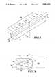
- FIG. 1illustrates a cylindrical lens
- FIG. 2illustrates a cross-section along the section shown in FIG. 1, of a cylindrical lens having an elliptical surface.
- FIG. 3is an example of a glass preform having the shape of a cylindrical lens.
- FIG. 4is another example of a glass preform having the shape of a cylindrical lens.
- FIG. 5is an example of a glass rod used to make a glass preform.
- FIG. 6is flow chart of a preferred method of forming the cylindrical lens of the present invention.
- FIG. 7is a cross-section of a cylindrical lens having a hyperbolic surface.
- FIG. 8is a cross-section of a cylindrical lens connected to a laser diode.
- FIG. 9is a perspective view of a laser diode bar and a cylindrical lens connected to form an assembly.
- FIG. 10is a diagram illustrating lens design.
- FIG. 11is a cross-section of a laser beam emitted from the exit aperture of a laser diode.
- FIGS. 1 and 2illustrate a cylindrical lens 10, comprising a body 11, having a first surface 12 and a second surface 14.
- the cylindrical lens 10has a cross-section that is constant along a cylindrical axis 16; the cross-section shown in FIG. 2 illustrates the same configuration as the outward facing end 17 illustrated in FIG. 1.
- light rays 18enter the body 11 of the cylindrical lens 10 through the first surface 12, and exit the lens 10 through the second surface 14. In other configurations, the direction of light propagation may be reversed.
- the light passing through the cylindrical lens 10is greatly affected by the shape of the first surface 12 and the second surface 14.
- the exiting lightmay be focused, de-focused, distorted, or otherwise changed in characteristics.
- the shape of the first surface 12is flat, and the second surface 14 is convex; therefore, such that the cylindrical lens 10 illustrated in FIGS. 1 and 2 is a collimating lens; light focused at input surface 12 will emerge from output surface 14 as parallel rays.
- the shapes of the surfaces 12,14may comprise any of a variety of configurations, such as concave, planar, and they may have different radiuses of curvature.
- a method for fabricating cylindrical microlensescomprising the steps: (a) forming a glass preform 20 (FIGS. 3 and 4) having a noncircular shape of a cylindrical lens, and (b) drawing the glass preform 20 to reduce its cross-sectional dimensions while retaining its cross-sectional shape, to provide a cylindrical microlens with a high numerical aperture or other desirable characteristics.
- each glass preform 20has a cylindrical cross section that comprises a first surface 22, and a second surface 24.
- the cross-sectionis constant along a cylindrical axis 26.
- FIG. 3shows a configuration wherein the glass preform 20a comprises a first surface 22a having a flat shape, and a second surface 24a having a curved shape.
- FIG. 4illustrates another configuration of the glass preform 20b, wherein a first surface 22b and a second surface 24b both comprise a curved shape.
- the specific cross-sectional shape of the preform 20is of course highly dependent upon the desired application of the cylindrical lens that will be formed from it.
- the shape of the preform 20is substantially retained throughout the drawing process, and therefore the cross-sectional shape of the preform 20 is chosen to transform some particular given input light distribution into some desired output light distribution in the final cylindrical microlens.
- either or both surfaces 22,24 of the preform 20may have the shape of a hyperbola, or in other embodiments either or both surfaces 22,24 may have the shape of an ellipse.
- each surface 22b,24bmay comprise the shape of a hyperbola in opposing relations as illustrated in that Figure.
- any of a number of conventional meanssuch as grinding, molding, or extruding, may be used.
- the quality of the finished cylindrical microlensis dependent upon the quality of the surfaces of the glass preform 20; preferably, the formation technique is chosen to produce a smooth and accurate surface on the glass preform.
- the method of the present inventionallows some leeway for "figure errors", which are slight errors in manufacturing the glass preform 20. For example, a 0.001 inch defect in the preform 20 will be reduced to insignificance in the final cylindrical microlens.
- a numerically controlled universal grindersuch as the model 1632 CNC Cylindrical Grinder with an optional CNC programmable workhead for nonround grinding, available from Weldon Machine Tool of York, Pa., is used to form the preform 20.
- the glass preform 20may be ground from a circular glass rod such as the rod 30 shown in FIG. 5.
- the rod 30is formed into an arbitrary shape; thus, the glass preform 20 can comprise an infinite variety of shapes.
- a mold of the desired shapeis tooled using conventional means. Then, conventionally, the molten glass is poured or pressed into the mold to fabricate the preform 20.
- the molding processhas the advantage of consistency and precision from preform to preform. The initial tooling cost for making the mold is expensive, but once the mold is formed, additional preforms 20 are easy to make.
- the glass preform 20After the glass preform 20 has been formed, it is drawn in a manner that is analogous to methods used in the optical fiber industry.
- the glass preform 20is heated at least to the minimum drawing temperature, and a microlens fiber of the desired dimensions is drawn from it.
- the cross-sectional shape of the glass preform 30remains constant as it is pulled, however, the cross-sectional dimensions get smaller and smaller.
- the surfacesbecome optically smooth from fire-polishing, which, it is believed, results because the temperature on the surface is greater than the inside temperature. Fire-polishing is a skin effect.
- the glass preform 20is heated to at least a softening temperature in an oven. It is preferable that the glass preform 20 comprise a material with a low softening temperature, such as SFL6, which is commercially available from Schott Glass of Duryea, Pa.
- a preferred method for fabricating the cylindrical lens 10is illustrated in the flow chart of FIG. 6.
- the glass preform 20is formed into the desired shape.
- the glass preform 20is placed in an oven and heated.
- the temperatureis carefully controlled so that the temperature is the minimum necessary for drawing; it is believed that a minimum temperature helps the preform 20 to maintain its shape during drawing.
- the drawing temperatureis preferably chosen so that the glass material of the preform 20 has a viscosity sufficient to permit drawing, but low enough that surface tension does not substantially deform the shape of the preform 20.
- the preform 20is drawn using analogous optical fiber techniques. As the preform 20 is drawn, a cylindrical microlens fiber is formed having reduced dimensions. For example, the dimensions may be reduced by a factor of fifty to one hundred.
- the final cross-sectional dimensions (the distance from the first optical surface to the second optical surface) of the drawn microlens fibermay be as small as 50 microns, or possibly as large as 1000 microns (1 millimeter).
- the microlens fibermay be spooled onto a cylinder, or it may be cut.
- the microlens fiberis cut into sections having a desired length which depends upon the application.
- the cylindrical lens 10 illustrated in FIG. 1represents a section of microlens fiber drawn according to the method of the present invention.
- Such cylindrical lenses 10have been formed experimentally with cross-sectional dimensions (the distance between the first surface 12 and the second surface 14) of between approximately 185 and 220 microns.
- the first surface 12comprises a flat surface
- the second surface 14comprises a curved surface.
- the second surface 14may comprise the shape of an ellipse.
- a focal line 40 of the ellipseis positioned on, or proximate to the flat surface 12.
- a divergent beam 42 emanating from the focal line 40will exit from the elliptical surface 14, and become a collimated beam 44, as illustrated in the cross-section of FIG. 2.
- the collimated beam 44is corrected for spherical aberration. That configuration has application in collimating a beam produced from a small aperture, such as a laser diode.
- a collimated beam 44 entering the cylindrical lens 10 through the elliptical surface 14will focus along the focal line 40.
- the lens 10 with the plano-elliptical configurationhas application in coupling light into an aperture, such as a detector or a waveguide in integrated optics. Cylindrical lenses 10 having this plano-elliptical configuration have been fabricated with focal lengths of 185 microns and 220 microns. The best results to date have been obtained with the cylindrical lens having the 220 micron focal length.
- the cylindrical lens 10may be designed with a flat first surface 12 and a powered second surface 14 that transforms a plane wave on axis into a perfect cylindrical wave.
- a "powered" surfaceis one that acts upon the beam to bend or otherwise shape it. The following are design considerations that may be considered when designing any particular lens.
- the optical path between the vertex of the dielectric interface 45 and the focus 46is equated with any other optical path to the focus 46, as shown in FIG. 10: ##EQU1## where n 1 and n 2 are the indices of refraction of the media to the left and right of the interface 45, respectively, and f is the focal length from the interface 45 to focus 46.
- a plano-elliptical cylindrical lens 10has been fabricated.
- a 0.75 cm wide preform 20was generated from a stock SFL6 rod on a numerically controlled universal grinder.
- the elliptical lenshad a focal length of 220 microns, and the index of refraction was 1.78.
- the lens thicknesswas chosen to approximately match the focal length of 220 microns so that the lens could be attached directly to the output facet of a laser diode using index matched optical cement.
- the first surface 12may be flat, and the second surface 14 may comprise the shape of a hyperbola.
- FIG. 7illustrates a cross-section of this preferred embodiment, and its effect on light passing through.
- a light beam 47 propagating from a focus 48diverges toward the cylindrical lens 10.
- the second surface 14the light becomes the collimated beam 49, which exits the flat first surface 12.
- the collimated beam 49is corrected for spherical aberration. That configuration may have application as a free-standing lens for collimating a beam from a line source such as a laser diode.
- a collimated beam 49 entering the cylindrical lens 10 through the flat first surface 12is unaffected until it reaches the hyperbolic second surface 14.
- the maximum numerical apertureis: ##EQU8##
- SFL6 hyperbolic lens in airits maximum numerical aperture is 0.83.
- the SFL6 elliptical lenswhich has a maximum numerical aperture of 1.47, has a much greater numerical aperture.
- the cylindrical lens 10amay be glued to an external surface, such as the output facet of a laser diode.
- a laser diode 50shown in cross-section, includes a semiconductor junction 52, which emits laser light from an emitting aperture 54 positioned on a facet 56. The junction 52 provides the gain material for lasing, and defines the laser cavity.
- a laser beam 58is emitted from the emitting aperture 54 in the direction of the arrow 60.
- FIG. 11is an example of a cross-section of a laser beam 58 at the emitting aperture 54. The narrow portion of the beam 58 defines a fast axis 62, and the wider portion of the beam 58 defines a long axis 64.
- the beam 58has a width 65, for example one micron and a length 66, for example seven microns; however, it is well-known that diffraction effects will cause the beam 58 to diverge much more quickly along the fast axis 62 than along the long axis 66.
- the facet 56is connected to the first surface 12a of the cylindrical lens 10a by any available means, such as gluing.
- an optical cement 67is used that is index matched to the lens 10.
- the facet 56 and the first surface 12amay be separated by an index matched material, such as oil, and the diode 50 may be connected to the lens 10a by other mechanical means. With the facet 56 connected to the first surface 12a, an efficient coupling of laser light from the laser diode 50 into the lens 10a is provided.
- the lens 10is positioned so that its cylindrical axis 16 (FIG. 1) is parallel to the long axis 64 (FIG. 11) of the laser diode 50.
- the powered second surface 14 of the lens 10is positioned to act upon the highly divergent fast axis 62 of the laser beam 58.
- the second surface 14includes the shape of an ellipse, and the emitting aperture 54 is positioned to be proximate to the focal point of that ellipse.
- the laser beam 58 exiting the lens 10ais substantially collimated along the fast axis 62.
- the cylindrical lens 10comprises a shape to cause the highly diverging fast axis 62 of the beam 58 to become less diverging.
- the curve of the second surface 14may be selected to cause the beam 58 to have a divergence along its fast axis 62 that is similar to the divergence of the beam 58 along its long axis 64, thereby providing a beam 58 that is approximately equally diverging along both axes 62, 64.
- the cylindrical lens 10may be connected to any type of laser diode 50 having a suitable shape for connecting the output facet 56 and the first surface 12.
- FIG. 9illustrates a laser diode bar 70, which emits laser light a substantial distance along its length 71.
- the cylindrical lens 10is connected to the laser diode bar 70 to form an assembly 72.
- the cylindrical axis 16 (FIG. 1) of the lens 10is positioned parallel to the long axis 64 of the laser diode bar 70.
- the curved second surface 14 of the lens 14may have any shape, it is preferable if the surface 14 has a shape selected so that a laser beam 74 emitted from the lens 10 is substantially collimated along its fast axis 62.
- the laser beam 74 emitted from the lens 10will be substantially collimated along its fast axis 62.
- the focal point of that ellipsemay vary with respect to the first surface 12. Therefore, in some applications, it may be preferable to design the focal point adjacent to the optical surface 12, at a position such as at a point 76, illustrated in FIG. 2.
- the position of the lens 10 with respect to the emitting aperture 54may be adjusted to a position that causes the output beam 74 to be substantially collimated along its fast axis 62. In this position, the beam 74 may exit the lens 10 at an angle depending upon the focal curve of the lens 10.
- a laser diode bar 70is an efficient, compact source of laser radiation, and when connected to the lens 10 in the laser diode-lens assembly 72, many applications are possible. For example, an array of the laser diode-lens assemblies 72 may be connected together to form an efficient, high-intensity collimated output.
- the laser diode-lens assembly 72provides a package that is well suited for pumping solid state laser material.
Landscapes
- Physics & Mathematics (AREA)
- Optics & Photonics (AREA)
- General Physics & Mathematics (AREA)
- Engineering & Computer Science (AREA)
- Electromagnetism (AREA)
- Chemical & Material Sciences (AREA)
- Condensed Matter Physics & Semiconductors (AREA)
- Life Sciences & Earth Sciences (AREA)
- General Life Sciences & Earth Sciences (AREA)
- Geochemistry & Mineralogy (AREA)
- Manufacturing & Machinery (AREA)
- Plasma & Fusion (AREA)
- Materials Engineering (AREA)
- Organic Chemistry (AREA)
- Optical Couplings Of Light Guides (AREA)
Abstract
Description
N.A. (numerical aperture)=n sin θ,
Δn≡n.sub.2 -n.sub.1 (5)
Claims (17)
Priority Applications (4)
| Application Number | Priority Date | Filing Date | Title |
|---|---|---|---|
| US07/591,409US5081639A (en) | 1990-10-01 | 1990-10-01 | Laser diode assembly including a cylindrical lens |
| EP19910907644EP0504330A4 (en) | 1990-10-01 | 1991-03-15 | Laser diode assembly including a cylindrical lens |
| PCT/US1991/001757WO1992006521A1 (en) | 1990-10-01 | 1991-03-15 | Laser diode assembly including a cylindrical lens |
| JP3507244AJPH05502980A (en) | 1990-10-01 | 1991-03-15 | Diode laser assembly with cylindrical lens |
Applications Claiming Priority (2)
| Application Number | Priority Date | Filing Date | Title |
|---|---|---|---|
| US07/591,409US5081639A (en) | 1990-10-01 | 1990-10-01 | Laser diode assembly including a cylindrical lens |
| US07/591,462US5080706A (en) | 1990-10-01 | 1990-10-01 | Method for fabrication of cylindrical microlenses of selected shape |
Publications (1)
| Publication Number | Publication Date |
|---|---|
| US5081639Atrue US5081639A (en) | 1992-01-14 |
Family
ID=27081143
Family Applications (1)
| Application Number | Title | Priority Date | Filing Date |
|---|---|---|---|
| US07/591,409Expired - LifetimeUS5081639A (en) | 1990-10-01 | 1990-10-01 | Laser diode assembly including a cylindrical lens |
Country Status (1)
| Country | Link |
|---|---|
| US (1) | US5081639A (en) |
Cited By (68)
| Publication number | Priority date | Publication date | Assignee | Title |
|---|---|---|---|---|
| US5155631A (en)* | 1990-10-01 | 1992-10-13 | The United States Of America As Represented By The Department Of Energy | Method for fabrication of cylindrical microlenses of selected shape |
| US5206878A (en)* | 1991-10-11 | 1993-04-27 | At&T Bell Laboratories | Wide strip diode laser employing a lens |
| US5208701A (en)* | 1991-12-24 | 1993-05-04 | Xerox Corporation | Wobble correction lens with binary diffractive optic surface and refractive cylindrical surface |
| US5229883A (en)* | 1991-10-28 | 1993-07-20 | Mcdonnell Douglas Corporation | Hybrid binary optics collimation fill optics |
| EP0562754A1 (en)* | 1992-03-26 | 1993-09-29 | Hewlett-Packard Company | Optical system for laser devices |
| US5268978A (en)* | 1992-12-18 | 1993-12-07 | Polaroid Corporation | Optical fiber laser and geometric coupler |
| US5293269A (en)* | 1991-05-03 | 1994-03-08 | Mcdonnell Douglas Corporation | Aspheric cylindrical lens and method of fabrication |
| US5307430A (en)* | 1992-11-30 | 1994-04-26 | The United States Of America As Represented By The United States Department Of Energy | Lensing duct |
| US5309454A (en)* | 1991-06-04 | 1994-05-03 | International Business Machines Corporation | Apparatus for wavelength conversion of laser light |
| FR2706077A1 (en)* | 1993-06-03 | 1994-12-09 | Saint Gobain Vitrage Int | Glass polyhedra and method of manufacture |
| EP0649203A1 (en)* | 1993-10-19 | 1995-04-19 | Toyota Jidosha Kabushiki Kaisha | Semiconductor laser with lens and method of manufacturing the same |
| US5410559A (en)* | 1994-02-04 | 1995-04-25 | Spectra-Physics Lasers, Inc. | Diode pumped laser with strong thermal lens crystal |
| US5426533A (en)* | 1992-07-15 | 1995-06-20 | Varo Inc. | Apparatus for enhancing collimation and improving collection efficiency from high aspect ratio linear energy sources |
| US5438187A (en)* | 1991-11-01 | 1995-08-01 | Spectra-Physics Scanning Systems, Inc. | Multiple focus optical system for data reading applications |
| US5450244A (en)* | 1992-12-18 | 1995-09-12 | Polaroid Corporation | Cylindrical fiber coupling lens with biaspheric surfaces |
| US5461637A (en)* | 1994-03-16 | 1995-10-24 | Micracor, Inc. | High brightness, vertical cavity semiconductor lasers |
| EP0691622A1 (en) | 1994-06-30 | 1996-01-10 | Symbol Technologies, Inc. | Beam shaping for optical scanners |
| US5504350A (en)* | 1992-08-12 | 1996-04-02 | Spectra-Physics Scanning Systems, Inc. | Lens configuration |
| US5577060A (en)* | 1994-02-04 | 1996-11-19 | Spectra Physics Lasers, Inc. | Diode pumped laser using crystals with strong thermal focussing |
| US5581414A (en)* | 1993-02-22 | 1996-12-03 | Blue Sky Research Incorporated | Microlens assemblies and couplers |
| US5607492A (en)* | 1994-11-04 | 1997-03-04 | Institut National D'optique | Method for forming a nonfull aperture luneberg lens with a graded index core and a homogenous cladding |
| US5610930A (en)* | 1995-03-02 | 1997-03-11 | Hughes Aircraft Company | Voltage adding diode laser array |
| US5617492A (en)* | 1996-02-06 | 1997-04-01 | The Regents Of The University Of California | Fiber optic coupling of a microlens conditioned, stacked semiconductor laser diode array |
| US5638214A (en)* | 1994-11-04 | 1997-06-10 | Institut National D'optique | Luneburg lens with a graded index core and homogeneous cladding |
| US5654831A (en)* | 1995-01-04 | 1997-08-05 | Hughes Electronics | Refractive ellipsoid optical surface without spherical aberration |
| DE19621263A1 (en)* | 1996-05-25 | 1997-11-27 | Univ Schiller Jena | Cylindrical collecting microlens for collecting light at focus line e.g. for communication optical signal processing |
| US5734766A (en)* | 1996-05-03 | 1998-03-31 | Laser Power Corporation | High efficiency fiber optic coupler that reduces beam divergence |
| US5745519A (en)* | 1996-11-12 | 1998-04-28 | Opto Power Corp. | Laser diode system |
| US5764274A (en)* | 1996-02-16 | 1998-06-09 | Presstek, Inc. | Apparatus for laser-discharge imaging and focusing elements for use therewith |
| WO1998025170A1 (en)* | 1996-12-06 | 1998-06-11 | Deutsche Telekom Ag | Device for optical coupling of a solid-state laser with an optical wave guide and a process for their production |
| US5771324A (en)* | 1996-05-03 | 1998-06-23 | Laser Power Corporation | Polarization-preserving fiber optic assembly |
| US5790576A (en)* | 1996-06-26 | 1998-08-04 | Sdl, Inc. | High brightness laser diode source |
| US5812179A (en)* | 1995-09-08 | 1998-09-22 | Presstek, Inc. | Apparatus for laser-discharge imaging including beam-guiding assemblies |
| US5825803A (en)* | 1995-12-14 | 1998-10-20 | Institut National D'optique | Multiple emitter laser diode assembly with graded-index fiber microlens |
| US5832150A (en)* | 1996-07-08 | 1998-11-03 | Laser Power Corporation | Side injection fiber optic coupler |
| US5859417A (en)* | 1991-06-14 | 1999-01-12 | Symbol Technologies, Inc. | Optical scanners having dual surface optical elements for dual working ranges |
| US5867327A (en)* | 1997-04-23 | 1999-02-02 | Blue Sky Research | Process for manufacturing cylindrical microlenses |
| US5923481A (en)* | 1996-11-27 | 1999-07-13 | The Regents Of The University Of California | Microlens frames for laser diode arrays |
| US5990925A (en)* | 1997-11-07 | 1999-11-23 | Presstek, Inc. | Diode-pumped system and method for producing image spots of constant size |
| US6029893A (en)* | 1995-05-22 | 2000-02-29 | Symbol Technologies, Inc. | Optical scanner having a reflected light collector including holographic optical elements |
| US6052236A (en)* | 1997-06-19 | 2000-04-18 | Matsushita Electric Industrial Co., Ltd. | Light source equipment optical scanner and data reading apparatus using the same |
| US6075803A (en)* | 1998-05-27 | 2000-06-13 | Excel/Quantronix, Inc. | Scalable vertically diode-pumped solid-state lasers |
| US6078437A (en)* | 1998-09-28 | 2000-06-20 | Blue Sky Research | Micro-optic lens with integral alignment member |
| US6151168A (en)* | 1996-10-28 | 2000-11-21 | Fraunhofer-Gesellschaft Zur Foerderung Der Angewandten Forschung E.V. | Optical array for symmetrization of laser diode beams |
| GB2354839A (en)* | 1999-09-02 | 2001-04-04 | Agilent Technologies Inc | Hyperbolic transfer lens for fibre optics |
| US6220514B1 (en) | 1991-07-25 | 2001-04-24 | Symbol Technologies, Inc. | Electro-optical scanner having stationary, multi-surface mirror having surfaces with aplanar profiles |
| US6312166B1 (en) | 1998-11-25 | 2001-11-06 | Nuvonyx, Inc. | Laser diode arrays and systems including structures for permitting optical power measurement therefrom |
| US6339577B1 (en) | 1998-07-14 | 2002-01-15 | Sony Corporation | Optical disk system, optical head device, and beam reshaping device |
| US6382513B1 (en) | 1991-07-25 | 2002-05-07 | Symbol Technologies, Inc. | Optical scanner with segmented collection mirror |
| WO2002090274A1 (en)* | 2001-05-09 | 2002-11-14 | Hamamatsu Photonics K.K. | Optical lens-use base material, optical lens, and production method for optical lens |
| US20040050105A1 (en)* | 2000-06-12 | 2004-03-18 | Nippon Sheet Glass Co., Ltd. | Method of manufacturing optical glass element, and optical glass element manufactured using the method |
| US6710926B2 (en) | 2002-04-10 | 2004-03-23 | The Regents Of The University Of California | Cylindrical microlens with an internally reflecting surface and a method of fabrication |
| US20040130792A1 (en)* | 2001-05-09 | 2004-07-08 | Yutaka Kusuyama | Optical lens and semiconductor laser device |
| US20040130791A1 (en)* | 2001-05-09 | 2004-07-08 | Yutaka Kusuyama | Optical lens-use base material, optical lens, and method of producing optical lens |
| US20040142639A1 (en)* | 2001-05-09 | 2004-07-22 | Yutaka Kusuyama | Optical lens-use base material, optical lens, and production method for optical lens |
| US20040141236A1 (en)* | 2001-05-09 | 2004-07-22 | Yutaka Kusuyama | Optical lens base material, optical lens, and method of producing optical lens |
| WO2004107017A1 (en)* | 2003-05-30 | 2004-12-09 | Fianium Limited | Optical multiplexer |
| US6948662B2 (en) | 1991-07-25 | 2005-09-27 | Symbol Technologies, Inc. | Two-dimensional optical code scanner with scanning pattern having region of greater apparent brightness for assisting alignment of scanning pattern |
| US7027691B1 (en) | 1999-10-05 | 2006-04-11 | Visteon Global Technologies, Inc. | Light coupling and distribution system |
| US20080219622A1 (en)* | 2005-10-29 | 2008-09-11 | Gsi Group Ltd. | Optical fibre coupling system |
| US20100000718A1 (en)* | 2008-06-02 | 2010-01-07 | Gerald Ho Kim | Silicon-based thermal energy transfer device and apparatus |
| US20100040098A1 (en)* | 2008-08-13 | 2010-02-18 | Institut National D'optique | Laser diode illuminator device and method for optically conditioning the light beam emitted by the same |
| US20100046569A1 (en)* | 2008-08-25 | 2010-02-25 | Gerald Ho Kim | Silicon-based lens support structure for diode laser |
| US20110110390A1 (en)* | 2009-11-06 | 2011-05-12 | Leister Process Technologies | Laser diode structure with integrated temperature-controlled beam shaping element and method for gas detection by means of a laser diode structure |
| RU2454760C1 (en)* | 2010-12-27 | 2012-06-27 | Российская академия наук Учреждение Российской академии наук Институт систем обработки изображений РАН (ИСОИ РАН) | Planar binary microlens |
| KR20200005083A (en)* | 2018-07-05 | 2020-01-15 | 삼성전자주식회사 | Light sensing system and electronic apparatus including the same |
| US20200313399A1 (en)* | 2017-10-12 | 2020-10-01 | Osram Oled Gmbh | Semiconductor laser and method of production for optoelectronic semiconductor parts |
| US11695247B2 (en)* | 2017-09-21 | 2023-07-04 | Panasonic intellectual property Management co., Ltd | Lens arrangements for varying numerical aperture in laser delivery systems |
Citations (12)
| Publication number | Priority date | Publication date | Assignee | Title |
|---|---|---|---|---|
| US3284722A (en)* | 1963-03-22 | 1966-11-08 | Rca Corp | Light coupling device |
| US3736518A (en)* | 1971-11-22 | 1973-05-29 | Rca Corp | Maser incorporating crystal having f-centers |
| US4009394A (en)* | 1975-10-28 | 1977-02-22 | The Magnavox Company | Remote control light transmitter employing a cylindrical lens |
| US4185891A (en)* | 1977-11-30 | 1980-01-29 | Grumman Aerospace Corporation | Laser diode collimation optics |
| US4268112A (en)* | 1977-05-18 | 1981-05-19 | International Telephone And Telegraph Corporation | Fiber optic connector using gradient index lenses |
| US4439861A (en)* | 1981-08-07 | 1984-03-27 | Mrj, Inc. | Solid state laser with controlled optical pumping |
| US4785459A (en)* | 1985-05-01 | 1988-11-15 | Baer Thomas M | High efficiency mode matched solid state laser with transverse pumping |
| US4837771A (en)* | 1985-05-01 | 1989-06-06 | Spectra-Physics, Inc. | High-efficiency mode-matched solid-state laser with transverse pumping and cascaded amplifier stages |
| US4890289A (en)* | 1987-12-04 | 1989-12-26 | Board Of Trustees Of Leland Stanford, Jr. University | Fiber coupled diode pumped moving solid state laser |
| US4908832A (en)* | 1985-05-01 | 1990-03-13 | Spectra-Physics, Inc. | High efficiency mode-matched solid-state laser with transverse pumping |
| US4945544A (en)* | 1988-03-29 | 1990-07-31 | Rohm Co., Ltd. | Diode laser pumped solid-state laser |
| US4962983A (en)* | 1987-12-21 | 1990-10-16 | Canon Kabushiki Kaisha | Laser optical apparatus |
- 1990
- 1990-10-01USUS07/591,409patent/US5081639A/ennot_activeExpired - Lifetime
Patent Citations (12)
| Publication number | Priority date | Publication date | Assignee | Title |
|---|---|---|---|---|
| US3284722A (en)* | 1963-03-22 | 1966-11-08 | Rca Corp | Light coupling device |
| US3736518A (en)* | 1971-11-22 | 1973-05-29 | Rca Corp | Maser incorporating crystal having f-centers |
| US4009394A (en)* | 1975-10-28 | 1977-02-22 | The Magnavox Company | Remote control light transmitter employing a cylindrical lens |
| US4268112A (en)* | 1977-05-18 | 1981-05-19 | International Telephone And Telegraph Corporation | Fiber optic connector using gradient index lenses |
| US4185891A (en)* | 1977-11-30 | 1980-01-29 | Grumman Aerospace Corporation | Laser diode collimation optics |
| US4439861A (en)* | 1981-08-07 | 1984-03-27 | Mrj, Inc. | Solid state laser with controlled optical pumping |
| US4785459A (en)* | 1985-05-01 | 1988-11-15 | Baer Thomas M | High efficiency mode matched solid state laser with transverse pumping |
| US4837771A (en)* | 1985-05-01 | 1989-06-06 | Spectra-Physics, Inc. | High-efficiency mode-matched solid-state laser with transverse pumping and cascaded amplifier stages |
| US4908832A (en)* | 1985-05-01 | 1990-03-13 | Spectra-Physics, Inc. | High efficiency mode-matched solid-state laser with transverse pumping |
| US4890289A (en)* | 1987-12-04 | 1989-12-26 | Board Of Trustees Of Leland Stanford, Jr. University | Fiber coupled diode pumped moving solid state laser |
| US4962983A (en)* | 1987-12-21 | 1990-10-16 | Canon Kabushiki Kaisha | Laser optical apparatus |
| US4945544A (en)* | 1988-03-29 | 1990-07-31 | Rohm Co., Ltd. | Diode laser pumped solid-state laser |
Non-Patent Citations (10)
| Title |
|---|
| J. A. Jordon, Jr. et al., "Kinoform Lenses", Appl. Opt., vol. 9, No. 8, pp. 1883-1887, Aug. 1970. |
| J. A. Jordon, Jr. et al., Kinoform Lenses , Appl. Opt., vol. 9, No. 8, pp. 1883 1887, Aug. 1970.* |
| L. B. Lesem et al., "The Kinoform: A New Wavefront Reconstruction Device", IBM J. Res. Dev., vol. 13, pp. 150-155, Mar. 1969. |
| L. B. Lesem et al., The Kinoform: A New Wavefront Reconstruction Device , IBM J. Res. Dev., vol. 13, pp. 150 155, Mar. 1969.* |
| M. Oikawa et al., "A Distributed-Index Planar Micro-Lens Made of Plastics", Jpn J. Appl. Phys., vol. 20, No. 1, pp. L51-L54, Jan. 1981. |
| M. Oikawa et al., A Distributed Index Planar Micro Lens Made of Plastics , Jpn J. Appl. Phys., vol. 20, No. 1, pp. L51 L54, Jan. 1981.* |
| N. F. Borrelli et al., "Photolytic technique for producing microlenses in photosensitive glass", Appl. Opt., vol. 24, No. 16, pp. 2520-2525, Aug. 15, 1985. |
| N. F. Borrelli et al., Photolytic technique for producing microlenses in photosensitive glass , Appl. Opt., vol. 24, No. 16, pp. 2520 2525, Aug. 15, 1985.* |
| T. M. Baer et al., "High Efficiency diode-bar pumped solid state laser using a tightly folded resonator", in Conference on Lasers and Electro-Optics (1989), paper FJ5. |
| T. M. Baer et al., High Efficiency diode bar pumped solid state laser using a tightly folded resonator , in Conference on Lasers and Electro Optics (1989), paper FJ5.* |
Cited By (109)
| Publication number | Priority date | Publication date | Assignee | Title |
|---|---|---|---|---|
| US5742038A (en)* | 1990-09-28 | 1998-04-21 | Symbol Technologies, Inc. | Beam shaping for optical scanners |
| US5155631A (en)* | 1990-10-01 | 1992-10-13 | The United States Of America As Represented By The Department Of Energy | Method for fabrication of cylindrical microlenses of selected shape |
| US5293269A (en)* | 1991-05-03 | 1994-03-08 | Mcdonnell Douglas Corporation | Aspheric cylindrical lens and method of fabrication |
| US5309454A (en)* | 1991-06-04 | 1994-05-03 | International Business Machines Corporation | Apparatus for wavelength conversion of laser light |
| US5859417A (en)* | 1991-06-14 | 1999-01-12 | Symbol Technologies, Inc. | Optical scanners having dual surface optical elements for dual working ranges |
| US6834805B2 (en) | 1991-07-25 | 2004-12-28 | Symbol Technologies, Inc. | Optical scanner with segmented collection mirror |
| USRE40102E1 (en)* | 1991-07-25 | 2008-02-26 | Symbol Technologies, Inc. | Electro-optical scanner having stationary, multi-surface mirror having surfaces with aplanar profiles |
| US6220514B1 (en) | 1991-07-25 | 2001-04-24 | Symbol Technologies, Inc. | Electro-optical scanner having stationary, multi-surface mirror having surfaces with aplanar profiles |
| US6382513B1 (en) | 1991-07-25 | 2002-05-07 | Symbol Technologies, Inc. | Optical scanner with segmented collection mirror |
| US6948662B2 (en) | 1991-07-25 | 2005-09-27 | Symbol Technologies, Inc. | Two-dimensional optical code scanner with scanning pattern having region of greater apparent brightness for assisting alignment of scanning pattern |
| US5206878A (en)* | 1991-10-11 | 1993-04-27 | At&T Bell Laboratories | Wide strip diode laser employing a lens |
| US5229883A (en)* | 1991-10-28 | 1993-07-20 | Mcdonnell Douglas Corporation | Hybrid binary optics collimation fill optics |
| US5438187A (en)* | 1991-11-01 | 1995-08-01 | Spectra-Physics Scanning Systems, Inc. | Multiple focus optical system for data reading applications |
| US5208701A (en)* | 1991-12-24 | 1993-05-04 | Xerox Corporation | Wobble correction lens with binary diffractive optic surface and refractive cylindrical surface |
| EP0562754A1 (en)* | 1992-03-26 | 1993-09-29 | Hewlett-Packard Company | Optical system for laser devices |
| US5426533A (en)* | 1992-07-15 | 1995-06-20 | Varo Inc. | Apparatus for enhancing collimation and improving collection efficiency from high aspect ratio linear energy sources |
| US5504350A (en)* | 1992-08-12 | 1996-04-02 | Spectra-Physics Scanning Systems, Inc. | Lens configuration |
| US5307430A (en)* | 1992-11-30 | 1994-04-26 | The United States Of America As Represented By The United States Department Of Energy | Lensing duct |
| US5268978A (en)* | 1992-12-18 | 1993-12-07 | Polaroid Corporation | Optical fiber laser and geometric coupler |
| US5546487A (en)* | 1992-12-18 | 1996-08-13 | Polaroid Corporation | Cylindrical fiber coupling lens with biaspheric surfaces |
| US5450244A (en)* | 1992-12-18 | 1995-09-12 | Polaroid Corporation | Cylindrical fiber coupling lens with biaspheric surfaces |
| US5581414A (en)* | 1993-02-22 | 1996-12-03 | Blue Sky Research Incorporated | Microlens assemblies and couplers |
| EP0627389A3 (en)* | 1993-06-03 | 1995-10-25 | Saint Gobain Vitrage | Glass polyhedra and manufacturing process. |
| FR2706077A1 (en)* | 1993-06-03 | 1994-12-09 | Saint Gobain Vitrage Int | Glass polyhedra and method of manufacture |
| US5553089A (en)* | 1993-10-19 | 1996-09-03 | Toyota Jidosha Kabushiki Kaisha | Semiconductor laser stack with lens and method of manufacturing the same |
| EP0649203A1 (en)* | 1993-10-19 | 1995-04-19 | Toyota Jidosha Kabushiki Kaisha | Semiconductor laser with lens and method of manufacturing the same |
| US5577060A (en)* | 1994-02-04 | 1996-11-19 | Spectra Physics Lasers, Inc. | Diode pumped laser using crystals with strong thermal focussing |
| US5410559A (en)* | 1994-02-04 | 1995-04-25 | Spectra-Physics Lasers, Inc. | Diode pumped laser with strong thermal lens crystal |
| US5627853A (en)* | 1994-03-16 | 1997-05-06 | Coherent, Inc. | Optimized laser energy conversion through automatic mode matched pumping |
| US5461637A (en)* | 1994-03-16 | 1995-10-24 | Micracor, Inc. | High brightness, vertical cavity semiconductor lasers |
| USRE40101E1 (en) | 1994-06-30 | 2008-02-26 | Symbol Technologies, Inc. | Electro-optical scanner having selectable scan pattern |
| EP0691622A1 (en) | 1994-06-30 | 1996-01-10 | Symbol Technologies, Inc. | Beam shaping for optical scanners |
| US5638214A (en)* | 1994-11-04 | 1997-06-10 | Institut National D'optique | Luneburg lens with a graded index core and homogeneous cladding |
| US5607492A (en)* | 1994-11-04 | 1997-03-04 | Institut National D'optique | Method for forming a nonfull aperture luneberg lens with a graded index core and a homogenous cladding |
| US5654831A (en)* | 1995-01-04 | 1997-08-05 | Hughes Electronics | Refractive ellipsoid optical surface without spherical aberration |
| US5610930A (en)* | 1995-03-02 | 1997-03-11 | Hughes Aircraft Company | Voltage adding diode laser array |
| US6029893A (en)* | 1995-05-22 | 2000-02-29 | Symbol Technologies, Inc. | Optical scanner having a reflected light collector including holographic optical elements |
| US5812179A (en)* | 1995-09-08 | 1998-09-22 | Presstek, Inc. | Apparatus for laser-discharge imaging including beam-guiding assemblies |
| US5825803A (en)* | 1995-12-14 | 1998-10-20 | Institut National D'optique | Multiple emitter laser diode assembly with graded-index fiber microlens |
| US5617492A (en)* | 1996-02-06 | 1997-04-01 | The Regents Of The University Of California | Fiber optic coupling of a microlens conditioned, stacked semiconductor laser diode array |
| US5764274A (en)* | 1996-02-16 | 1998-06-09 | Presstek, Inc. | Apparatus for laser-discharge imaging and focusing elements for use therewith |
| US5734766A (en)* | 1996-05-03 | 1998-03-31 | Laser Power Corporation | High efficiency fiber optic coupler that reduces beam divergence |
| US5771324A (en)* | 1996-05-03 | 1998-06-23 | Laser Power Corporation | Polarization-preserving fiber optic assembly |
| DE19621263A1 (en)* | 1996-05-25 | 1997-11-27 | Univ Schiller Jena | Cylindrical collecting microlens for collecting light at focus line e.g. for communication optical signal processing |
| US5790576A (en)* | 1996-06-26 | 1998-08-04 | Sdl, Inc. | High brightness laser diode source |
| US5832150A (en)* | 1996-07-08 | 1998-11-03 | Laser Power Corporation | Side injection fiber optic coupler |
| US6151168A (en)* | 1996-10-28 | 2000-11-21 | Fraunhofer-Gesellschaft Zur Foerderung Der Angewandten Forschung E.V. | Optical array for symmetrization of laser diode beams |
| US5745519A (en)* | 1996-11-12 | 1998-04-28 | Opto Power Corp. | Laser diode system |
| US5923481A (en)* | 1996-11-27 | 1999-07-13 | The Regents Of The University Of California | Microlens frames for laser diode arrays |
| US6370298B2 (en) | 1996-12-06 | 2002-04-09 | Deutsche Telekom Ag | Device for optical coupling of a solid-state laser with an optical wave guide and a process for their production |
| WO1998025170A1 (en)* | 1996-12-06 | 1998-06-11 | Deutsche Telekom Ag | Device for optical coupling of a solid-state laser with an optical wave guide and a process for their production |
| US5867327A (en)* | 1997-04-23 | 1999-02-02 | Blue Sky Research | Process for manufacturing cylindrical microlenses |
| US6052236A (en)* | 1997-06-19 | 2000-04-18 | Matsushita Electric Industrial Co., Ltd. | Light source equipment optical scanner and data reading apparatus using the same |
| US5990925A (en)* | 1997-11-07 | 1999-11-23 | Presstek, Inc. | Diode-pumped system and method for producing image spots of constant size |
| US6075803A (en)* | 1998-05-27 | 2000-06-13 | Excel/Quantronix, Inc. | Scalable vertically diode-pumped solid-state lasers |
| US6339577B1 (en) | 1998-07-14 | 2002-01-15 | Sony Corporation | Optical disk system, optical head device, and beam reshaping device |
| US6078437A (en)* | 1998-09-28 | 2000-06-20 | Blue Sky Research | Micro-optic lens with integral alignment member |
| US6312166B1 (en) | 1998-11-25 | 2001-11-06 | Nuvonyx, Inc. | Laser diode arrays and systems including structures for permitting optical power measurement therefrom |
| US6349159B1 (en)* | 1999-09-02 | 2002-02-19 | Agilent Technologies, Inc. | Lenses that launch high bandwidth modes into a fiber optic cable while eliminating feedback to a laser |
| GB2354839B (en)* | 1999-09-02 | 2003-06-25 | Agilent Technologies Inc | Lenses for fibre optics |
| GB2354839A (en)* | 1999-09-02 | 2001-04-04 | Agilent Technologies Inc | Hyperbolic transfer lens for fibre optics |
| US7027691B1 (en) | 1999-10-05 | 2006-04-11 | Visteon Global Technologies, Inc. | Light coupling and distribution system |
| US20040050105A1 (en)* | 2000-06-12 | 2004-03-18 | Nippon Sheet Glass Co., Ltd. | Method of manufacturing optical glass element, and optical glass element manufactured using the method |
| US7003983B2 (en)* | 2000-06-12 | 2006-02-28 | Nippon Sheet Glass Co., Ltd. | Method of manufacturing optical glass element, and optical glass element manufactured using the method |
| US6947226B2 (en) | 2001-05-09 | 2005-09-20 | Hamamatsu Photonics K.K. | Optical lens-use base material, optical lens, and method of producing optical lens |
| US20040130792A1 (en)* | 2001-05-09 | 2004-07-08 | Yutaka Kusuyama | Optical lens and semiconductor laser device |
| US6801369B2 (en) | 2001-05-09 | 2004-10-05 | Hamamatsu Photonics K.K. | Preform for an optical lens, an optical lens, and a method of manufacturing an optical lens |
| US7743631B2 (en) | 2001-05-09 | 2010-06-29 | Hamamatsu Photonics K.K. | Method of forming an optical lens by drawing material with curved surface parts |
| US20040141236A1 (en)* | 2001-05-09 | 2004-07-22 | Yutaka Kusuyama | Optical lens base material, optical lens, and method of producing optical lens |
| US20040264002A1 (en)* | 2001-05-09 | 2004-12-30 | Hamamatsu Photonics K.K. | Preform for an optical lens, an optical lens, and a method of manufacturing an optical lens |
| US20040142639A1 (en)* | 2001-05-09 | 2004-07-22 | Yutaka Kusuyama | Optical lens-use base material, optical lens, and production method for optical lens |
| CN101329413B (en)* | 2001-05-09 | 2010-10-13 | 浜松光子学株式会社 | Optical lens |
| US20040130791A1 (en)* | 2001-05-09 | 2004-07-08 | Yutaka Kusuyama | Optical lens-use base material, optical lens, and method of producing optical lens |
| US20060007555A1 (en)* | 2001-05-09 | 2006-01-12 | Hamamatsu Photonics K.K. | Optical lens preform, optical lens, and method of making optical lens |
| US7833089B2 (en) | 2001-05-09 | 2010-11-16 | Hamamatsu Photonics K.K. | Optical lens preform, optical lens, and method of making optical lens |
| CN100471804C (en)* | 2001-05-09 | 2009-03-25 | 浜松光子学株式会社 | Base material for optical lens, and method for manufacturing optical lens |
| US7038860B2 (en) | 2001-05-09 | 2006-05-02 | Hamamatsu Photonics K.K. | Preform for an optical lens, an optical lens, and a method of manufacturing an optical lens |
| US20060181778A1 (en)* | 2001-05-09 | 2006-08-17 | Hamamatsu Photonics K.K. | Optical lens and semiconductor laser apparatus |
| US7110193B2 (en) | 2001-05-09 | 2006-09-19 | Hamamatsu Photonics K.K. | Optical lens preform, optical lens, and method of making optical lens |
| US7145724B2 (en) | 2001-05-09 | 2006-12-05 | Hamamatsu Photonics K.K. | Optical lens and semiconductor laser device |
| US7322877B2 (en) | 2001-05-09 | 2008-01-29 | Hamamatsu Photonics K.K. | Production method for optical lens |
| JP4659335B2 (en)* | 2001-05-09 | 2011-03-30 | 浜松ホトニクス株式会社 | Optical lens base material, optical lens, and optical lens manufacturing method |
| WO2002090274A1 (en)* | 2001-05-09 | 2002-11-14 | Hamamatsu Photonics K.K. | Optical lens-use base material, optical lens, and production method for optical lens |
| JPWO2002090274A1 (en)* | 2001-05-09 | 2004-08-19 | 浜松ホトニクス株式会社 | Optical lens base material, optical lens, and optical lens manufacturing method |
| US7561335B2 (en) | 2001-05-09 | 2009-07-14 | Hamamatsu Photonics K.K. | Optical lens and semiconductor laser apparatus |
| US6948341B2 (en) | 2002-04-10 | 2005-09-27 | The Regents Of The University Of California | Cylindrical microlens with an internally reflecting surface and a method of fabrication |
| US6710926B2 (en) | 2002-04-10 | 2004-03-23 | The Regents Of The University Of California | Cylindrical microlens with an internally reflecting surface and a method of fabrication |
| US20040129025A1 (en)* | 2002-04-10 | 2004-07-08 | Beach Raymond J. | Cylindrical microlens with an internally reflecting surface and a method of fabrication |
| US7376296B2 (en) | 2003-05-30 | 2008-05-20 | Fianium Limited | Optical multiplexer |
| WO2004107017A1 (en)* | 2003-05-30 | 2004-12-09 | Fianium Limited | Optical multiplexer |
| US20080219622A1 (en)* | 2005-10-29 | 2008-09-11 | Gsi Group Ltd. | Optical fibre coupling system |
| US20100000718A1 (en)* | 2008-06-02 | 2010-01-07 | Gerald Ho Kim | Silicon-based thermal energy transfer device and apparatus |
| US8490678B2 (en) | 2008-06-02 | 2013-07-23 | Gerald Ho Kim | Silicon-based thermal energy transfer device and apparatus |
| US7873091B2 (en) | 2008-08-13 | 2011-01-18 | Institut National D'optique | Laser diode illuminator device and method for optically conditioning the light beam emitted by the same |
| US20100040098A1 (en)* | 2008-08-13 | 2010-02-18 | Institut National D'optique | Laser diode illuminator device and method for optically conditioning the light beam emitted by the same |
| US20100046569A1 (en)* | 2008-08-25 | 2010-02-25 | Gerald Ho Kim | Silicon-based lens support structure for diode laser |
| US8238401B2 (en)* | 2008-08-25 | 2012-08-07 | Gerald Ho Kim | Silicon-based lens support structure for diode laser |
| US20110110390A1 (en)* | 2009-11-06 | 2011-05-12 | Leister Process Technologies | Laser diode structure with integrated temperature-controlled beam shaping element and method for gas detection by means of a laser diode structure |
| US8594143B2 (en)* | 2009-11-06 | 2013-11-26 | Axetris Ag | Laser diode structure with integrated temperature-controlled beam shaping element and method for gas detection by means of a laser diode structure |
| RU2454760C1 (en)* | 2010-12-27 | 2012-06-27 | Российская академия наук Учреждение Российской академии наук Институт систем обработки изображений РАН (ИСОИ РАН) | Planar binary microlens |
| US20230291166A1 (en)* | 2017-09-21 | 2023-09-14 | Panasonic intellectual property Management co., Ltd | Lens arrangements for varying numerical aperture in laser delivery systems |
| US11695247B2 (en)* | 2017-09-21 | 2023-07-04 | Panasonic intellectual property Management co., Ltd | Lens arrangements for varying numerical aperture in laser delivery systems |
| US12136793B2 (en)* | 2017-09-21 | 2024-11-05 | Panasonic intellectual property Management co., Ltd | Lens arrangements for varying numerical aperture in laser delivery systems |
| US20200313399A1 (en)* | 2017-10-12 | 2020-10-01 | Osram Oled Gmbh | Semiconductor laser and method of production for optoelectronic semiconductor parts |
| US11735887B2 (en)* | 2017-10-12 | 2023-08-22 | Osram Oled Gmbh | Semiconductor laser and method of production for optoelectronic semiconductor parts |
| US11870214B2 (en)* | 2017-10-12 | 2024-01-09 | Osram Oled Gmbh | Semiconductor laser and method of production for optoelectronic semiconductor parts |
| US20240088622A1 (en)* | 2017-10-12 | 2024-03-14 | Osram Oled Gmbh | Semiconductor laser and method of production for optoelectronic semiconductor parts |
| KR20200005083A (en)* | 2018-07-05 | 2020-01-15 | 삼성전자주식회사 | Light sensing system and electronic apparatus including the same |
| US11962119B2 (en) | 2018-07-05 | 2024-04-16 | Samsung Electronics Co., Ltd. | Light sensing system and electronic apparatus including the same |
Similar Documents
| Publication | Publication Date | Title |
|---|---|---|
| US5081639A (en) | Laser diode assembly including a cylindrical lens | |
| US5080706A (en) | Method for fabrication of cylindrical microlenses of selected shape | |
| US5155631A (en) | Method for fabrication of cylindrical microlenses of selected shape | |
| KR102107159B1 (en) | Manual aligned single element telescope for improved package brightness | |
| US6963682B2 (en) | Beam altering fiber lens device and method of manufacture | |
| US7068883B2 (en) | Symmetric, bi-aspheric lens for use in optical fiber collimator assemblies | |
| Snyder et al. | Fast diffraction-limited cylindrical microlenses | |
| US20050069257A1 (en) | Fiber lens with multimode pigtail | |
| US4744620A (en) | Optical coupler | |
| JPS6370209A (en) | Photoconductive fiber having tapered end section with lens | |
| KR100295535B1 (en) | Quadaxial gradient index lens | |
| WO1992006521A1 (en) | Laser diode assembly including a cylindrical lens | |
| US5953162A (en) | Segmented GRIN anamorphic lens | |
| JP2896947B2 (en) | Optical fiber end structure and method of manufacturing the same | |
| JP2001503161A (en) | Axial gradient index coupler | |
| RU2114451C1 (en) | Telescopic gradient lens | |
| EP0562754A1 (en) | Optical system for laser devices | |
| Goering et al. | Gradient index microlenses for laser diode applications | |
| Presby | Design and Fabrication of Efficient Fiber Microlenses | |
| CN120703913A (en) | Optical coupling microsystem containing fast axis beam shaping | |
| CN111650689A (en) | A fiber-integrated microlens group | |
| JP2004046105A (en) | Optical collimator component and optical device structure | |
| Nishiwaki et al. | Ultra-Small Optical Components: Lens And" Hybrid Lens" | |
| JP2004046104A (en) | Partially spherical lens and partially spherical lens array |
Legal Events
| Date | Code | Title | Description |
|---|---|---|---|
| AS | Assignment | Owner name:UNITED STATES OF AMERICA, THE, AS REPRESENTED BY T Free format text:ASSIGNMENT OF ASSIGNORS INTEREST.;ASSIGNORS:SNYDER, JAMES J.;REICHERT, PATRICK;REEL/FRAME:005765/0818 Effective date:19900928 | |
| AS | Assignment | Owner name:REGENTS OF THE UNIVERSITY OF CALIFORNIA, THE, CALI Free format text:ASSIGNMENT OF ASSIGNORS INTEREST;ASSIGNOR:UNITED STATES OF AMERICA, THE, AS REPRESENTED BY THE DEPARTMENT OF ENERGY;REEL/FRAME:006804/0747 Effective date:19931027 | |
| FEPP | Fee payment procedure | Free format text:PAT HOLDER CLAIMS SMALL ENTITY STATUS - SMALL BUSINESS (ORIGINAL EVENT CODE: SM02); ENTITY STATUS OF PATENT OWNER: SMALL ENTITY | |
| REMI | Maintenance fee reminder mailed | ||
| FPAY | Fee payment | Year of fee payment:4 | |
| SULP | Surcharge for late payment | ||
| REMI | Maintenance fee reminder mailed | ||
| FEPP | Fee payment procedure | Free format text:PAT HOLDER CLAIMS SMALL ENTITY STATUS - NONPROFIT ORG. (ORIGINAL EVENT CODE: SM03); ENTITY STATUS OF PATENT OWNER: SMALL ENTITY | |
| FP | Lapsed due to failure to pay maintenance fee | Effective date:20000114 | |
| FPAY | Fee payment | Year of fee payment:8 | |
| SULP | Surcharge for late payment | ||
| STCF | Information on status: patent grant | Free format text:PATENTED CASE | |
| PRDP | Patent reinstated due to the acceptance of a late maintenance fee | Effective date:20000714 | |
| REMI | Maintenance fee reminder mailed | ||
| FPAY | Fee payment | Year of fee payment:12 | |
| SULP | Surcharge for late payment | Year of fee payment:11 | |
| AS | Assignment | Owner name:LAWRENCE LIVERMORE NATIONAL SECURITY LLC, CALIFORN Free format text:ASSIGNMENT OF ASSIGNORS INTEREST;ASSIGNOR:THE REGENTS OF THE UNIVERSITY OF CALIFORNIA;REEL/FRAME:021217/0050 Effective date:20080623 |