US5080461A - Retracting optical fiber connector - Google Patents
Retracting optical fiber connectorDownload PDFInfo
- Publication number
- US5080461A US5080461AUS07/608,102US60810290AUS5080461AUS 5080461 AUS5080461 AUS 5080461AUS 60810290 AUS60810290 AUS 60810290AUS 5080461 AUS5080461 AUS 5080461A
- Authority
- US
- United States
- Prior art keywords
- fiber
- housing
- alignment
- groove
- grooves
- Prior art date
- Legal status (The legal status is an assumption and is not a legal conclusion. Google has not performed a legal analysis and makes no representation as to the accuracy of the status listed.)
- Expired - Lifetime
Links
Images


Classifications
- G—PHYSICS
- G02—OPTICS
- G02B—OPTICAL ELEMENTS, SYSTEMS OR APPARATUS
- G02B6/00—Light guides; Structural details of arrangements comprising light guides and other optical elements, e.g. couplings
- G02B6/24—Coupling light guides
- G02B6/36—Mechanical coupling means
- G02B6/38—Mechanical coupling means having fibre to fibre mating means
- G02B6/3807—Dismountable connectors, i.e. comprising plugs
- G02B6/3809—Dismountable connectors, i.e. comprising plugs without a ferrule embedding the fibre end, i.e. with bare fibre end
- G—PHYSICS
- G02—OPTICS
- G02B—OPTICAL ELEMENTS, SYSTEMS OR APPARATUS
- G02B6/00—Light guides; Structural details of arrangements comprising light guides and other optical elements, e.g. couplings
- G02B6/24—Coupling light guides
- G02B6/26—Optical coupling means
- G02B6/32—Optical coupling means having lens focusing means positioned between opposed fibre ends
- G—PHYSICS
- G02—OPTICS
- G02B—OPTICAL ELEMENTS, SYSTEMS OR APPARATUS
- G02B6/00—Light guides; Structural details of arrangements comprising light guides and other optical elements, e.g. couplings
- G02B6/24—Coupling light guides
- G02B6/36—Mechanical coupling means
- G02B6/38—Mechanical coupling means having fibre to fibre mating means
- G02B6/3807—Dismountable connectors, i.e. comprising plugs
- G02B6/3833—Details of mounting fibres in ferrules; Assembly methods; Manufacture
- G02B6/3834—Means for centering or aligning the light guide within the ferrule
- G02B6/3838—Means for centering or aligning the light guide within the ferrule using grooves for light guides
- G02B6/3839—Means for centering or aligning the light guide within the ferrule using grooves for light guides for a plurality of light guides
- G—PHYSICS
- G02—OPTICS
- G02B—OPTICAL ELEMENTS, SYSTEMS OR APPARATUS
- G02B6/00—Light guides; Structural details of arrangements comprising light guides and other optical elements, e.g. couplings
- G02B6/24—Coupling light guides
- G02B6/36—Mechanical coupling means
- G02B6/38—Mechanical coupling means having fibre to fibre mating means
- G02B6/3807—Dismountable connectors, i.e. comprising plugs
- G02B6/3873—Connectors using guide surfaces for aligning ferrule ends, e.g. tubes, sleeves, V-grooves, rods, pins, balls
- G02B6/3885—Multicore or multichannel optical connectors, i.e. one single ferrule containing more than one fibre, e.g. ribbon type
- G—PHYSICS
- G02—OPTICS
- G02B—OPTICAL ELEMENTS, SYSTEMS OR APPARATUS
- G02B6/00—Light guides; Structural details of arrangements comprising light guides and other optical elements, e.g. couplings
- G02B6/24—Coupling light guides
- G02B6/36—Mechanical coupling means
- G02B6/38—Mechanical coupling means having fibre to fibre mating means
- G02B6/3807—Dismountable connectors, i.e. comprising plugs
- G02B6/381—Dismountable connectors, i.e. comprising plugs of the ferrule type, e.g. fibre ends embedded in ferrules, connecting a pair of fibres
- G02B6/3818—Dismountable connectors, i.e. comprising plugs of the ferrule type, e.g. fibre ends embedded in ferrules, connecting a pair of fibres of a low-reflection-loss type
- G02B6/382—Dismountable connectors, i.e. comprising plugs of the ferrule type, e.g. fibre ends embedded in ferrules, connecting a pair of fibres of a low-reflection-loss type with index-matching medium between light guides
- G—PHYSICS
- G02—OPTICS
- G02B—OPTICAL ELEMENTS, SYSTEMS OR APPARATUS
- G02B6/00—Light guides; Structural details of arrangements comprising light guides and other optical elements, e.g. couplings
- G02B6/24—Coupling light guides
- G02B6/36—Mechanical coupling means
- G02B6/38—Mechanical coupling means having fibre to fibre mating means
- G02B6/3807—Dismountable connectors, i.e. comprising plugs
- G02B6/381—Dismountable connectors, i.e. comprising plugs of the ferrule type, e.g. fibre ends embedded in ferrules, connecting a pair of fibres
- G02B6/3818—Dismountable connectors, i.e. comprising plugs of the ferrule type, e.g. fibre ends embedded in ferrules, connecting a pair of fibres of a low-reflection-loss type
- G02B6/3821—Dismountable connectors, i.e. comprising plugs of the ferrule type, e.g. fibre ends embedded in ferrules, connecting a pair of fibres of a low-reflection-loss type with axial spring biasing or loading means
- G—PHYSICS
- G02—OPTICS
- G02B—OPTICAL ELEMENTS, SYSTEMS OR APPARATUS
- G02B6/00—Light guides; Structural details of arrangements comprising light guides and other optical elements, e.g. couplings
- G02B6/24—Coupling light guides
- G02B6/36—Mechanical coupling means
- G02B6/38—Mechanical coupling means having fibre to fibre mating means
- G02B6/3807—Dismountable connectors, i.e. comprising plugs
- G02B6/3833—Details of mounting fibres in ferrules; Assembly methods; Manufacture
- G02B6/3847—Details of mounting fibres in ferrules; Assembly methods; Manufacture with means preventing fibre end damage, e.g. recessed fibre surfaces
- G02B6/3849—Details of mounting fibres in ferrules; Assembly methods; Manufacture with means preventing fibre end damage, e.g. recessed fibre surfaces using mechanical protective elements, e.g. caps, hoods, sealing membranes
Definitions
- This inventionrelates to optical fiber connectors, and more particularly to an optical fiber connector for backplane use that physically protects the fibers during the coupling and decoupling while at the same time providing alignment of fibers.
- optical fiber connectionsare effected by embedding the fiber ends in a cylindrical sleeve, polishing the fiber ends, and inserting the prepared ends into an alignment ferrule, which optically and mechanically mates the fiber ends along a common axis.
- the connector endsmay be attached to the ferrule by, for example, threaded or bayonet-type coupling nuts.
- the connectors and connection methodology of the prior artexposes the fiber ends to damage or contamination. As a result, added effort must be expended to protect, clean and maintain the ends. Further, threaded or bayonet-type coupling nuts are not compatible with many optical backplane applications since access to connectors is often not possible. Frequently also, large spring retention forces are required to maintain the fiber ends in aligned contact in the presence of mechanical shock or vibrational energy.
- the difficulty of adapting the conventional optical fiber connector technology to making gang or array connectionsis another drawback, especially in the connection of fibers in a backplane.
- the popular v-groove fiber connectorallows high density interconnection, but is susceptible to misalignments of the fiber ends.
- the current gang-type backplane optical fiber connectorsare limited typically to two dozen or fewer interconnections, which is far fewer than needed for many applications. Further, as with the simpler fiber connectors, the current backplane optical fiber connectors do not sufficiently protect the fiber ends, tend to be expensive, and require high retention forces to meet shock and vibration conditions.
- a broad object of the inventionis to connect one or more pairs of optical fibers quickly and reliably, and in precise and stable end alignment.
- Another object of the inventionis to increase the reliability and ease of use of gang-type optical fiber connectors.
- Another object of the inventionis to reduce the cost of backplane optical fiber connections.
- a further object of the inventionis to avoid the exposure of optical fiber ends to atmospheric contamination or to unintended physical contacts during a mating or unmating operation.
- a further object of the inventionis to eliminate the use of alignment ferrules in making optical fiber connections thereby reducing connector size constraints.
- two sets of optical fiber ends to be connectedare contained in opposing v-grooves in the respective interiors of a first (left) and a second (right) mating housings.
- the interiorsare accessed by doors that open only when the housings are mated.
- the housing accessesare closed to protect the fibers.
- the two housingscombine to form a protective enclosure for the mated fibers.
- Each housingincludes mechanisms which are actuated by surface features of the other housing during mating engagement, to open the access doors to the housing interiors.
- each fiber v-grooved subassemblycontains an alignment feature and alignment ball or pin.
- the primary fiber groovecontains a fixed alignment ball whose center is on the fiber core axis. The ball serves as both alignment mechanism and optical lens.
- the v-groove in which the fiber and ball are containedis formed on the underside of a pivotally mounted fiber subassembly or finger.
- the fingerWhen not engaged to the second (right) mating housing, the finger is held in a retracted position. As the two housings engage, an actuator slidably mounted in the left housing is moved inwardly by contact with the right housing. This allows the fiber-containing finger in the left housing to commence pivoting downward on a detent of the actuator. Toward the end of the stroke, this ball and fiber subassembly comes to rest in an alignment groove formed in the floor of the right housing. Since the ball and fiber of the right housing is already situated in the alignment groove system, the fiber ends are set in axial alignment.
- the two alignment ballsnot only provide accurate axial alignment of the two fibers, but also efficient focusing of the light emanating from the fiber ends through the optically transparent balls.
- the lensing action of the alignment ballsserves the function of centering the cores of the connecting fibers.
- each ballIn order to capture a maximum amount of light emitted from the fiber end, each ball must be situated very precisely with respect to the fiber end. It is advantageous therefore to fix the aligning balls with a transparent and index matching epoxy. Further, each ball is coated with an anti-reflective (AR) coating to further reduce reflections and loss.
- ARanti-reflective
- the basic inventive conceptmay be applied to connecting a multiplicity of optical fibers in a backplane.
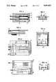
- FIG. 1is a sectional side view of the two housings in their unmated position
- FIG. 2is a sectional side view of the two housings in their mated position
- FIGS. 3, 4 and 5are a bottom view, side view and front view respectively of the fiber-containing subassembly of the left housing;
- FIGS. 6, 7 and 8are top, side and front views respectively of the left housing.
- FIGS. 9, 10 and 11are top, side and front views respectively of the actuator element and door of the left housing
- FIG. 12is a top view of the groove-containing floor of the right housing
- FIG. 13is a schematic perspective sketch of a gang-type variation of the single fiber-containing subassembly of the left housing.
- FIG. 14is a front view of the right housing.
- FIG. 1shows two mating housings 10, 40, which are the "left” and “right” housings.
- Left housing 10comprises a platform 11 pivotally mounted by pin 30 fixed in the sides 22, 23 of housing 10.
- the exterior surfaces of housing 10, as well as certain of the internal detail,are shown in FIGS. 6, 7 and 8.
- a fiber subassembly 12mounts on the underside of platform 11.
- An optical fiber 14extends through an entrance 8 of rear wall 21 of housing 10 also providing strain relief.
- Fiber subassembly 12includes one or more v-grooves 15 for receiving the unjacketed end of optical fiber 14.
- Two sets of groovesare shown formed in subassembly 12 in the illustrative example, for connecting two pairs of optical fibers; but it is understood that the inventive principles apply equally to connecting any number of fibers in a first set to mating fibers in a second set.
- the grooves 15, 16, 17are seen in phantom in FIG. 6.
- each v-groove 15receives a small length of the jacketed portion of fiber 14 to strain relieve the unjacketed portion.
- An alignment ball 18is affixed in a relatively deeper and wider v-groove 17 disposed at the end of the fiber groove 15. The diameter of ball 18 in relation to the depth of v-groove 17 places the center of ball 18 on the optic axis of the optical fiber positioned in the groove-containing surface of the fiber subassembly 12.
- Right housing 40includes sidewalls 52, 53, and a floor 41 in which is formed fiber v-grooves 45 as seen in FIG. 12.
- Fiber 42enters housing 40 through a fiber entrance 9 in the rear wall 54.
- An enlarged v-groove 44receives the jacketed end of fiber 42.
- a recessed v-groove 51which serves the same purpose as v-groove 17, contains a fixedly mounted alignment ball lens 39.
- the diameter of ball 39 in reaction to the depth of v-groove 51is such that the center of ball 39 is on the optic axis defined by the core of the fiber 42 and the depth of the fiber groove 45.
- the alignment balls 18 and 39are affixed in position in their respective v-grooves by epoxy compound.
- the index-matching epoxyalso provides for a low loss transmission channel between the fiber end and the ball's surface.
- Right housing 40includes a retracting entrance door 46 which mounts in a door slide 47.
- door 46is biased into a forward direction by action of spring 48. In this position, door 46 closes the entrance to the interior of housing 40.
- left housing 10has an access door 25, which permits access to the interior of housing 10.
- Door 25is mounted on the foot 32 of actuator 27 by pivot pin 26, as seen in FIG. 10 for example.
- the entrance to the interior of housing 10is sealed by door 25.
- Actuator 27is normally biased in a forward position against the interior side of front wall 24 of housing 10.
- the platform 11 and its optical fiber(s)is raised or lowered as actuator 27 moves in and out of the cavity 28.
- the platform 11In the position shown in FIG. 1, the platform 11 is supported in a raised or retracted position, in which the fiber end is disposed upwardly in the interior of housing 10.
- the ramp 19 of platform 11moves downward under the bias of loading spring 20 pressing on the topside of platform 11.
- the fiber 13thereby is lowered toward the plane of the top surface of the lower interior floor of housing 10.
- alignment ball 18 of the left housingengages alignment groove 51 of right housing 40; and, in accordance with the invention, optically aligns with the alignment ball 39.
- the two alignment ballsare both situated in optical alignment in the grooves 51, as depicted in FIG. 2.
- the fiber platform 11should be mounted on its pivot pin 30 within the interior of housing 10 with a certain amount of freedom of movement in the direction of the pivot pin axis.
- the freedomwill allow the platform 11 to adjust if, during mating, the ball 18 does not happen to align with its center precisely in the plane that bisects the v-groove 51. In such case, the lateral freedom will allow the ball 18 to seek out the v-groove sides and thereby assume its desired alignment.
- an alignment finger 35 seen in FIG. 7is formed on the upper guide surface 31 of housing 10. Finger 35 closely engages into the mating alignment slot 36 of housing 40, thus preventing the grooves containing the mating fibers from vibrating out of alignment.
- the inventionoffers a further advantage, in that it is not critical to maintain a very precise separation between the alignment balls 18, 39 when the balls are both disposed in groove 51. This is due to the fact that the radii of the balls 18, 39 and the distance of the balls from the light-emitting ends of the respective fibers 14, 42 are carefully set and thereafter fixed with epoxy, to assure that light entering a ball from the adjacent fiber travels in parallel rays.
- the epoxyshould have an index of refraction that matches the refractive indices of the glass fiber core and the alignment ball. Matching the refractive indexes allows the epoxy to be extended advantageously around the balls and the fiber ends, an expedient that reduces the incidence of loss at the point of connection.
- a 2200 ⁇ 280 ⁇ AR coating of silicon dioxide (SiO 2 )increasing transmission to better than 99.9%.
- the balls, 18, 39may be formed of sapphire and in this embodiment are 300 microns in diameter.
- the fiber-to-lens surface separationis about 85 microns.
- the inventionhas been described so far in an embodiment in which one or two optical fibers are contained in each of the housings 10, 40.
- a multiplicity of optical fiberscan be accommodated in each housing to effect a gang connection.
- FIG. 13shows an array of arms, each denoted 60, and each serving the fiber-mounting purpose of the platform 11.
- Each arm 60includes a fiber subassembly 61 that is formed with a fiber groove and a v-groove recess for an alignment ball (not shown), as has been described above with respect to platform 11 and holder 12.
- each arm 60is biased downward by a spring (not shown) such as spring 20.
- Each arm 60functions substantially the same as the structure illustrated in FIGS. 1 and 2, to allow individual fibers and their associated alignment balls to be guided into alignment slots contained in a mating housing.
- magnetic, electromagnetic, or shape memory alloy actuatorscan be used in place of the mechanical actuator means shown here.
- FIG. 13can easily accommodate in one gang-connector structure different sizes (diameters) of optical fibers as well as variations in ball diameter.
- the shape and depth of the fiber-containing v-grooves, and that of the ball-containing v-groovescan be varied and set to achieve the foregoing.
Landscapes
- Physics & Mathematics (AREA)
- General Physics & Mathematics (AREA)
- Optics & Photonics (AREA)
- Mechanical Coupling Of Light Guides (AREA)
Abstract
Description
Claims (11)
Priority Applications (1)
| Application Number | Priority Date | Filing Date | Title |
|---|---|---|---|
| US07/608,102US5080461A (en) | 1990-10-31 | 1990-10-31 | Retracting optical fiber connector |
Applications Claiming Priority (1)
| Application Number | Priority Date | Filing Date | Title |
|---|---|---|---|
| US07/608,102US5080461A (en) | 1990-10-31 | 1990-10-31 | Retracting optical fiber connector |
Publications (1)
| Publication Number | Publication Date |
|---|---|
| US5080461Atrue US5080461A (en) | 1992-01-14 |
Family
ID=24435030
Family Applications (1)
| Application Number | Title | Priority Date | Filing Date |
|---|---|---|---|
| US07/608,102Expired - LifetimeUS5080461A (en) | 1990-10-31 | 1990-10-31 | Retracting optical fiber connector |
Country Status (1)
| Country | Link |
|---|---|
| US (1) | US5080461A (en) |
Cited By (42)
| Publication number | Priority date | Publication date | Assignee | Title |
|---|---|---|---|---|
| US5224186A (en)* | 1991-05-29 | 1993-06-29 | Sumitomo Electric Industries, Ltd. | Optical fiber connector with housing assembly for an assuring complete connection |
| US5440655A (en)* | 1993-12-29 | 1995-08-08 | At&T Corp. | Optical fiber connector bypass device and method using same |
| US5602955A (en)* | 1995-06-07 | 1997-02-11 | Mcdonnell Douglas Corporation | Microactuator for precisely aligning an optical fiber and an associated fabrication method |
| US5606635A (en)* | 1995-06-07 | 1997-02-25 | Mcdonnell Douglas Corporation | Fiber optic connector having at least one microactuator for precisely aligning an optical fiber and an associated fabrication method |
| WO1997023796A1 (en)* | 1995-12-22 | 1997-07-03 | Minnesota Mining And Manufacturing Company | Optical fiber connector using fiber spring force and alignment groove |
| US5692089A (en)* | 1996-04-11 | 1997-11-25 | Fotron, Inc. | Multiple fiber positioner for optical fiber connection |
| US5757997A (en)* | 1995-12-22 | 1998-05-26 | Minnesota Mining And Manufacturing Company | Optical fiber connector using fiber spring force alignment groove |
| US5813902A (en)* | 1997-04-14 | 1998-09-29 | Minnesota Mining And Manufacturing Company | Optical fiber end-face preparation and connector assembly |
| US5881198A (en)* | 1995-06-07 | 1999-03-09 | Mcdonnell Douglas Corporation | Microactuator for precisely positioning an optical fiber and an associated method |
| EP0957380A1 (en)* | 1998-05-12 | 1999-11-17 | Amphenol Socapex | Optical connector |
| US6006768A (en)* | 1996-06-07 | 1999-12-28 | 3M Innovative Properties Company | Fiber optic cable cleaner |
| US6026210A (en)* | 1997-02-14 | 2000-02-15 | 3M Innovative Properties Company | Fiber optic connector spring |
| US6085004A (en)* | 1998-02-03 | 2000-07-04 | 3M Innovative Properties Company | Optical fiber connector using photocurable adhesive |
| US6125227A (en)* | 1997-03-10 | 2000-09-26 | 3M Innovative Properties Company | Fiber optic cable cleaner |
| US6196730B1 (en) | 1998-06-22 | 2001-03-06 | 3M Innovative Properties Company | Fiber optic connector containing a curable adhesive composition |
| US6318902B1 (en) | 1996-03-12 | 2001-11-20 | 3M Innovative Properties Company | Optical connector assembly using partial large diameter alignment features |
| US6412986B1 (en) | 2000-06-30 | 2002-07-02 | Berg Technology, Inc. | Adapter for assembling multiple optical connectors |
| US20030044125A1 (en)* | 2001-08-31 | 2003-03-06 | Sepehr Kiani | Waferized fiber optic connector |
| US6567583B2 (en) | 1999-03-30 | 2003-05-20 | Lucent Technologies Inc. | Mode converter and method |
| US6646887B2 (en)* | 2002-03-20 | 2003-11-11 | Tektronix, Inc. | Removable mechanical attachment system for electronic assemblies |
| US6682230B1 (en) | 2000-08-09 | 2004-01-27 | Berg Technology, Inc. | Optical connector and printed circuit board assembly with movable connection |
| US6805493B2 (en) | 1996-03-12 | 2004-10-19 | 3M Innovative Properties Company | Optical connector assembly using partial large diameter alignment features |
| US6821025B2 (en) | 2002-07-18 | 2004-11-23 | Westover Scientific, Inc. | Fiber-optic endface cleaning assembly and method |
| EP1403670A3 (en)* | 2002-09-27 | 2005-01-26 | Japan Aviation Electronics Industry, Limited | Optical fiber connector with optical fiber end protector |
| US20050078914A1 (en)* | 2003-10-14 | 2005-04-14 | 3M Innovative Properties Company | Optical and opto-electronic interconnect alignment system |
| EP1530068A3 (en)* | 2001-08-31 | 2005-11-30 | Teradyne, Inc. | Flat fiber optic connector |
| EP1666943A4 (en)* | 2003-09-01 | 2007-05-09 | Hirose Electric Co Ltd | OPTICAL CONNECTOR WITH PROTECTIVE MECHANISM |
| US7232262B2 (en) | 2002-07-18 | 2007-06-19 | Westover Scientific, Inc. | Fiber-optic endface cleaning apparatus and method |
| US20070292086A1 (en)* | 2006-06-19 | 2007-12-20 | Nielson Jeffrey D | Hard coating on rugged vee groove connectors |
| US20070292096A1 (en)* | 2006-06-19 | 2007-12-20 | Nielson Jeffrey D | Rugged expanded beam connector |
| US20090252459A1 (en)* | 2006-06-19 | 2009-10-08 | Nielson Jeffrey D | Expanded beam connector concepts |
| US20100178008A1 (en)* | 2009-01-14 | 2010-07-15 | Nielson Jeffrey D | High Density Optical Connector |
| US20100272404A1 (en)* | 2009-04-27 | 2010-10-28 | Hon Hai Precision Industry Co., Ltd. | Optical connector with a protecting mechanism for protecting an optical module thereof |
| US20110158587A1 (en)* | 2009-12-31 | 2011-06-30 | Hon Hai Precision Industry Co., Ltd. | Optical fiber connector and optical fiber connector assembly having same |
| US20120082421A1 (en)* | 2010-09-30 | 2012-04-05 | Hon Hai Precision Industry Co., Ltd. | Optical connector having incorporated with power |
| US20130084045A1 (en)* | 2011-09-29 | 2013-04-04 | Fujitsu Limited | Optical connector and electronic equipment using the same |
| US20150147031A1 (en)* | 2012-06-26 | 2015-05-28 | Japan Aviation Electronics Industry, Limited | Backplane optical connector |
| WO2015126905A3 (en)* | 2014-02-18 | 2015-12-03 | 3M Innovative Properties Company | Optical ferrule and connector |
| US20170017047A1 (en)* | 2012-10-05 | 2017-01-19 | 3M Innovative Properties Company | Optical connector |
| US9599771B2 (en) | 2006-06-19 | 2017-03-21 | Commscope, Inc. Of North Carolina | Expanded beam connector concepts |
| US11002920B2 (en)* | 2015-11-13 | 2021-05-11 | CommScope Connectivity Belgium BVBA | Fiber optic connection system |
| US20230003947A1 (en)* | 2019-12-02 | 2023-01-05 | 3M Innovative Properties Company | Optical Connector Assembly |
Citations (6)
| Publication number | Priority date | Publication date | Assignee | Title |
|---|---|---|---|---|
| US4323300A (en)* | 1978-12-16 | 1982-04-06 | Plessey Handel Und Investments Ag | Optical fibre connectors |
| US4657341A (en)* | 1983-08-03 | 1987-04-14 | Siemens Aktiengesellschaft | Connector for light waveguides and method of producing same |
| US4889406A (en)* | 1985-04-11 | 1989-12-26 | Sezerman Omur M | Tilt adjustable optical fibre connectors |
| US4900118A (en)* | 1987-05-22 | 1990-02-13 | Furukawa Electric Co., Ltd. | Multiple-fiber optical component and method for manufacturing of the same |
| US4962990A (en)* | 1988-03-25 | 1990-10-16 | Ngk Insulators, Ltd. | Optical device |
| US4973127A (en)* | 1989-05-31 | 1990-11-27 | At&T Bell Laboratories | Multifiber optical connector and method of making same |
- 1990
- 1990-10-31USUS07/608,102patent/US5080461A/ennot_activeExpired - Lifetime
Patent Citations (6)
| Publication number | Priority date | Publication date | Assignee | Title |
|---|---|---|---|---|
| US4323300A (en)* | 1978-12-16 | 1982-04-06 | Plessey Handel Und Investments Ag | Optical fibre connectors |
| US4657341A (en)* | 1983-08-03 | 1987-04-14 | Siemens Aktiengesellschaft | Connector for light waveguides and method of producing same |
| US4889406A (en)* | 1985-04-11 | 1989-12-26 | Sezerman Omur M | Tilt adjustable optical fibre connectors |
| US4900118A (en)* | 1987-05-22 | 1990-02-13 | Furukawa Electric Co., Ltd. | Multiple-fiber optical component and method for manufacturing of the same |
| US4962990A (en)* | 1988-03-25 | 1990-10-16 | Ngk Insulators, Ltd. | Optical device |
| US4973127A (en)* | 1989-05-31 | 1990-11-27 | At&T Bell Laboratories | Multifiber optical connector and method of making same |
Cited By (80)
| Publication number | Priority date | Publication date | Assignee | Title |
|---|---|---|---|---|
| US5224186A (en)* | 1991-05-29 | 1993-06-29 | Sumitomo Electric Industries, Ltd. | Optical fiber connector with housing assembly for an assuring complete connection |
| US5440655A (en)* | 1993-12-29 | 1995-08-08 | At&T Corp. | Optical fiber connector bypass device and method using same |
| EP0661571A3 (en)* | 1993-12-29 | 1996-03-20 | At & T Corp | Optical bypass device. |
| US5542013A (en)* | 1993-12-29 | 1996-07-30 | At&T Corp. | Optical fiber connector bypass device |
| US5881198A (en)* | 1995-06-07 | 1999-03-09 | Mcdonnell Douglas Corporation | Microactuator for precisely positioning an optical fiber and an associated method |
| US5602955A (en)* | 1995-06-07 | 1997-02-11 | Mcdonnell Douglas Corporation | Microactuator for precisely aligning an optical fiber and an associated fabrication method |
| US5606635A (en)* | 1995-06-07 | 1997-02-25 | Mcdonnell Douglas Corporation | Fiber optic connector having at least one microactuator for precisely aligning an optical fiber and an associated fabrication method |
| WO1997023796A1 (en)* | 1995-12-22 | 1997-07-03 | Minnesota Mining And Manufacturing Company | Optical fiber connector using fiber spring force and alignment groove |
| US5757997A (en)* | 1995-12-22 | 1998-05-26 | Minnesota Mining And Manufacturing Company | Optical fiber connector using fiber spring force alignment groove |
| RU2178193C2 (en)* | 1995-12-22 | 2002-01-10 | Миннесота Майнинг Энд Мэнюфекчуринг Компани | Fiber-optical connector with employment of elastic fiber and centering groove |
| US6318902B1 (en) | 1996-03-12 | 2001-11-20 | 3M Innovative Properties Company | Optical connector assembly using partial large diameter alignment features |
| US6805493B2 (en) | 1996-03-12 | 2004-10-19 | 3M Innovative Properties Company | Optical connector assembly using partial large diameter alignment features |
| US5692089A (en)* | 1996-04-11 | 1997-11-25 | Fotron, Inc. | Multiple fiber positioner for optical fiber connection |
| US6006768A (en)* | 1996-06-07 | 1999-12-28 | 3M Innovative Properties Company | Fiber optic cable cleaner |
| US6026210A (en)* | 1997-02-14 | 2000-02-15 | 3M Innovative Properties Company | Fiber optic connector spring |
| US6125227A (en)* | 1997-03-10 | 2000-09-26 | 3M Innovative Properties Company | Fiber optic cable cleaner |
| US5813902A (en)* | 1997-04-14 | 1998-09-29 | Minnesota Mining And Manufacturing Company | Optical fiber end-face preparation and connector assembly |
| US6085004A (en)* | 1998-02-03 | 2000-07-04 | 3M Innovative Properties Company | Optical fiber connector using photocurable adhesive |
| US6151433A (en)* | 1998-02-03 | 2000-11-21 | 3M Innovative Properties Company | Optical fiber connector using photocurable adhesive |
| US6275642B1 (en) | 1998-05-12 | 2001-08-14 | Amphenol Socapex | Optical connector |
| EP0957380A1 (en)* | 1998-05-12 | 1999-11-17 | Amphenol Socapex | Optical connector |
| FR2778752A1 (en)* | 1998-05-12 | 1999-11-19 | Socapex Amphenol | OPTICAL CONNECTOR |
| US6196730B1 (en) | 1998-06-22 | 2001-03-06 | 3M Innovative Properties Company | Fiber optic connector containing a curable adhesive composition |
| US6567583B2 (en) | 1999-03-30 | 2003-05-20 | Lucent Technologies Inc. | Mode converter and method |
| US6412986B1 (en) | 2000-06-30 | 2002-07-02 | Berg Technology, Inc. | Adapter for assembling multiple optical connectors |
| US6682230B1 (en) | 2000-08-09 | 2004-01-27 | Berg Technology, Inc. | Optical connector and printed circuit board assembly with movable connection |
| EP1530068A3 (en)* | 2001-08-31 | 2005-11-30 | Teradyne, Inc. | Flat fiber optic connector |
| US20030044125A1 (en)* | 2001-08-31 | 2003-03-06 | Sepehr Kiani | Waferized fiber optic connector |
| WO2003021322A3 (en)* | 2001-08-31 | 2004-01-08 | Teradyne Inc | Waferized fiber optic connector |
| US6769814B2 (en) | 2001-08-31 | 2004-08-03 | Teradyne, Inc. | Waferized fiber optic connector |
| US6646887B2 (en)* | 2002-03-20 | 2003-11-11 | Tektronix, Inc. | Removable mechanical attachment system for electronic assemblies |
| US20050105859A1 (en)* | 2002-07-18 | 2005-05-19 | Westover Scientific, Inc. | Fiber-optic endface cleaning assembly and method |
| US6821025B2 (en) | 2002-07-18 | 2004-11-23 | Westover Scientific, Inc. | Fiber-optic endface cleaning assembly and method |
| US7147490B2 (en) | 2002-07-18 | 2006-12-12 | Westover Scientific, Inc. | Fiber-optic endface cleaning assembly and method |
| US7232262B2 (en) | 2002-07-18 | 2007-06-19 | Westover Scientific, Inc. | Fiber-optic endface cleaning apparatus and method |
| US20070196056A1 (en)* | 2002-07-18 | 2007-08-23 | Westover Scientific, Inc. | Fiber-optic endface cleaning assembly and method |
| US20080152284A1 (en)* | 2002-07-18 | 2008-06-26 | Westover Scientific, Inc. | Fiber-optic endface cleaning apparatus and method |
| US7566176B2 (en) | 2002-07-18 | 2009-07-28 | Westover Scientific, Inc. | Fiber-optic endface cleaning apparatus and method |
| EP1403670A3 (en)* | 2002-09-27 | 2005-01-26 | Japan Aviation Electronics Industry, Limited | Optical fiber connector with optical fiber end protector |
| EP1666943A4 (en)* | 2003-09-01 | 2007-05-09 | Hirose Electric Co Ltd | OPTICAL CONNECTOR WITH PROTECTIVE MECHANISM |
| US20050078914A1 (en)* | 2003-10-14 | 2005-04-14 | 3M Innovative Properties Company | Optical and opto-electronic interconnect alignment system |
| US6984073B2 (en) | 2003-10-14 | 2006-01-10 | 3M Innovative Properties Company | Optical and opto-electronic interconnect alignment system |
| US20070292086A1 (en)* | 2006-06-19 | 2007-12-20 | Nielson Jeffrey D | Hard coating on rugged vee groove connectors |
| US20070292096A1 (en)* | 2006-06-19 | 2007-12-20 | Nielson Jeffrey D | Rugged expanded beam connector |
| US20090252459A1 (en)* | 2006-06-19 | 2009-10-08 | Nielson Jeffrey D | Expanded beam connector concepts |
| US7625129B2 (en) | 2006-06-19 | 2009-12-01 | Commscope, Inc. Of North Carolina | Rugged expanded beam connector |
| US10048449B2 (en) | 2006-06-19 | 2018-08-14 | Commscope, Inc. Of North Carolina | Expanded beam connector concepts |
| US7563032B2 (en) | 2006-06-19 | 2009-07-21 | Commscope, Inc. Of North Carolina | Hard coating on rugged VEE groove connectors |
| US8393804B2 (en) | 2006-06-19 | 2013-03-12 | Commscope, Inc. Of North Carolina | Expanded beam connector concepts |
| US9599771B2 (en) | 2006-06-19 | 2017-03-21 | Commscope, Inc. Of North Carolina | Expanded beam connector concepts |
| US10534141B2 (en) | 2006-06-19 | 2020-01-14 | Commscope, Inc. Of North Carolina | Expanded beam connector concepts |
| US20100178008A1 (en)* | 2009-01-14 | 2010-07-15 | Nielson Jeffrey D | High Density Optical Connector |
| US8038354B2 (en) | 2009-01-14 | 2011-10-18 | Commscope, Inc. Of North Carolina | High density optical connector |
| US8491200B2 (en)* | 2009-04-27 | 2013-07-23 | Hon Hai Precision Industry Co., Ltd. | Optical connector with a protecting mechanism for protecting an optical module thereof |
| US20100272404A1 (en)* | 2009-04-27 | 2010-10-28 | Hon Hai Precision Industry Co., Ltd. | Optical connector with a protecting mechanism for protecting an optical module thereof |
| US8408812B2 (en)* | 2009-12-31 | 2013-04-02 | Hon Hai Precision Industry Co., Ltd. | Optical fiber connector with rotatable cover and optical fiber connector assembly having same |
| TWI457628B (en)* | 2009-12-31 | 2014-10-21 | Hon Hai Prec Ind Co Ltd | Optical fiber coupling component and optical fiber coupling module |
| US20110158587A1 (en)* | 2009-12-31 | 2011-06-30 | Hon Hai Precision Industry Co., Ltd. | Optical fiber connector and optical fiber connector assembly having same |
| US20120082421A1 (en)* | 2010-09-30 | 2012-04-05 | Hon Hai Precision Industry Co., Ltd. | Optical connector having incorporated with power |
| US8876412B2 (en)* | 2011-09-29 | 2014-11-04 | Fujitsu Limited | Optical connector and electronic equipment using the same |
| US20130084045A1 (en)* | 2011-09-29 | 2013-04-04 | Fujitsu Limited | Optical connector and electronic equipment using the same |
| US20150147031A1 (en)* | 2012-06-26 | 2015-05-28 | Japan Aviation Electronics Industry, Limited | Backplane optical connector |
| US9182555B2 (en)* | 2012-06-26 | 2015-11-10 | Japan Aviation Electronics Industry, Limited | Backplane optical connector |
| EP3521881A1 (en)* | 2012-10-05 | 2019-08-07 | 3M Innovative Properties Company | Optical connector |
| US11119282B2 (en) | 2012-10-05 | 2021-09-14 | 3M Innovative Properties Company | Optical connector |
| US20170017044A1 (en)* | 2012-10-05 | 2017-01-19 | 3M Innovative Properties Company | Optical connector |
| US11719889B2 (en) | 2012-10-05 | 2023-08-08 | 3M Innovative Properties Company | Optical connector |
| US20170017047A1 (en)* | 2012-10-05 | 2017-01-19 | 3M Innovative Properties Company | Optical connector |
| US10139571B2 (en)* | 2012-10-05 | 2018-11-27 | 3M Innovative Properties Company | Optical connector |
| US10168486B2 (en)* | 2012-10-05 | 2019-01-01 | 3M Innovative Properties Company | Optical connector |
| US10641969B2 (en) | 2012-10-05 | 2020-05-05 | 3M Innovative Properties Company | Optical connector |
| JP2019191591A (en)* | 2014-02-18 | 2019-10-31 | スリーエム イノベイティブ プロパティズ カンパニー | Optical ferrule and connector |
| WO2015126905A3 (en)* | 2014-02-18 | 2015-12-03 | 3M Innovative Properties Company | Optical ferrule and connector |
| CN106030361A (en)* | 2014-02-18 | 2016-10-12 | 3M创新有限公司 | Optical ferrule and connector |
| US11029472B2 (en)* | 2014-02-18 | 2021-06-08 | 3M Innovative Properties Company | Optical ferrule and connector |
| JP2017506365A (en)* | 2014-02-18 | 2017-03-02 | スリーエム イノベイティブ プロパティズ カンパニー | Optical ferrule and connector |
| US20170168248A1 (en)* | 2014-02-18 | 2017-06-15 | 3M Innovative Properties Company | Optical ferrule and connector |
| US11002920B2 (en)* | 2015-11-13 | 2021-05-11 | CommScope Connectivity Belgium BVBA | Fiber optic connection system |
| US20230003947A1 (en)* | 2019-12-02 | 2023-01-05 | 3M Innovative Properties Company | Optical Connector Assembly |
| US11977261B2 (en)* | 2019-12-02 | 2024-05-07 | 3M Innovative Properties Company | Optical connector assembly |
Similar Documents
| Publication | Publication Date | Title |
|---|---|---|
| US5080461A (en) | Retracting optical fiber connector | |
| US9638873B2 (en) | Receptacle ferrule assemblies with gradient index lenses and fiber optic connectors using same | |
| US4534616A (en) | Fiber optic connector having lens | |
| US6086263A (en) | Active device receptacle | |
| US9377589B2 (en) | Small-form-factor fiber optic interface devices with an internal lens | |
| US10139573B2 (en) | Cable assemblies, optical connector assemblies, and optical connector subassemblies employing a unitary alignment pin and cover | |
| US5481634A (en) | Connector for optical fiber | |
| US4913514A (en) | Fiber optic connector | |
| US9651743B2 (en) | Gradient index (GRIN) lens holders employing a recessed cover, and optical connectors and methods incorporating the same | |
| US9091822B2 (en) | Ferrules having optical pathways and fiber optic connectors using same | |
| US9417406B2 (en) | Cable assemblies and optical connector assemblies employing a unitary alignment pin and translating element | |
| US10025050B2 (en) | Receptacle ferrules with monolithic lens system and fiber optic connectors using same | |
| EP2856230B1 (en) | Optical connector and method of coupling optical connectors | |
| US20060002662A1 (en) | Small form factor, field-installable connector | |
| JP6938515B2 (en) | Dust mitigation optical connector | |
| WO1997023797A1 (en) | Receptacle for electro-optical device | |
| US20170010426A1 (en) | Substrate mounted optical receptacle | |
| EP1356329B1 (en) | Protective shutter for fibre optic connector | |
| Childers et al. | Next-generation, high-density, low-cost, multimode optical backplane interconnect | |
| Brusberg et al. | Slim push-pull fiber array connector for optical chips | |
| US7563032B2 (en) | Hard coating on rugged VEE groove connectors | |
| CA2359002A1 (en) | Optoelectric module for multi-fiber arrays | |
| JPS6111711A (en) | Optical fiber coupler | |
| WO1998034141A2 (en) | Multiport housing with a plurality of sockets for fibre optic plugs | |
| Kevern et al. | O Passive Alignment in Connectors and Splices |
Legal Events
| Date | Code | Title | Description |
|---|---|---|---|
| AS | Assignment | Owner name:AMERICAN TELEPHONE AND TELEGRAPH COMPANY, NEW YORK Free format text:ASSIGNMENT OF ASSIGNORS INTEREST.;ASSIGNOR:PIMPINELLA, RICHARD J.;REEL/FRAME:005508/0827 Effective date:19901031 | |
| STCF | Information on status: patent grant | Free format text:PATENTED CASE | |
| FEPP | Fee payment procedure | Free format text:PAYOR NUMBER ASSIGNED (ORIGINAL EVENT CODE: ASPN); ENTITY STATUS OF PATENT OWNER: LARGE ENTITY | |
| FPAY | Fee payment | Year of fee payment:4 | |
| FEPP | Fee payment procedure | Free format text:PAYOR NUMBER ASSIGNED (ORIGINAL EVENT CODE: ASPN); ENTITY STATUS OF PATENT OWNER: LARGE ENTITY Free format text:PAYER NUMBER DE-ASSIGNED (ORIGINAL EVENT CODE: RMPN); ENTITY STATUS OF PATENT OWNER: LARGE ENTITY | |
| FPAY | Fee payment | Year of fee payment:8 | |
| AS | Assignment | Owner name:LUCENT TECHNOLOGIES INC., NEW JERSEY Free format text:ASSIGNMENT OF ASSIGNORS INTEREST;ASSIGNOR:AT&T CORP.;REEL/FRAME:012059/0893 Effective date:19960329 | |
| AS | Assignment | Owner name:FITEL USA CORPORATION, GEORGIA Free format text:ASSIGNMENT OF ASSIGNORS INTEREST;ASSIGNOR:LUCENT TECHNOLOGIES;REEL/FRAME:012946/0578 Effective date:20011116 | |
| FPAY | Fee payment | Year of fee payment:12 | |
| AS | Assignment | Owner name:COMMSCOPE SOLUTIONS PROPERTIES, LLC, NORTH CAROLIN Free format text:ASSIGNMENT OF ASSIGNORS INTEREST;ASSIGNOR:FURUKAWA ELECTRIC NORTH AMERICA, INC. (FORMERLY KNOWN AS FITEL USA CORP.);REEL/FRAME:019974/0797 Effective date:20040415 | |
| AS | Assignment | Owner name:COMMSCOPE, INC. OF NORTH CAROLINA, NORTH CAROLINA Free format text:MERGER;ASSIGNOR:COMMSCOPE SOLUTIONS PROPERTIES, LLC;REEL/FRAME:019991/0643 Effective date:20061220 Owner name:COMMSCOPE, INC. OF NORTH CAROLINA,NORTH CAROLINA Free format text:MERGER;ASSIGNOR:COMMSCOPE SOLUTIONS PROPERTIES, LLC;REEL/FRAME:019991/0643 Effective date:20061220 | |
| AS | Assignment | Owner name:BANK OF AMERICA, N.A., AS ADMINISTRATIVE AGENT, CA Free format text:SECURITY AGREEMENT;ASSIGNORS:COMMSCOPE, INC. OF NORTH CAROLINA;ALLEN TELECOM, LLC;ANDREW CORPORATION;REEL/FRAME:020362/0241 Effective date:20071227 Owner name:BANK OF AMERICA, N.A., AS ADMINISTRATIVE AGENT,CAL Free format text:SECURITY AGREEMENT;ASSIGNORS:COMMSCOPE, INC. OF NORTH CAROLINA;ALLEN TELECOM, LLC;ANDREW CORPORATION;REEL/FRAME:020362/0241 Effective date:20071227 | |
| AS | Assignment | Owner name:COMMSCOPE, INC. OF NORTH CAROLINA, NORTH CAROLINA Free format text:PATENT RELEASE;ASSIGNOR:BANK OF AMERICA, N.A., AS ADMINISTRATIVE AGENT;REEL/FRAME:026039/0005 Effective date:20110114 Owner name:ALLEN TELECOM LLC, NORTH CAROLINA Free format text:PATENT RELEASE;ASSIGNOR:BANK OF AMERICA, N.A., AS ADMINISTRATIVE AGENT;REEL/FRAME:026039/0005 Effective date:20110114 Owner name:ANDREW LLC (F/K/A ANDREW CORPORATION), NORTH CAROL Free format text:PATENT RELEASE;ASSIGNOR:BANK OF AMERICA, N.A., AS ADMINISTRATIVE AGENT;REEL/FRAME:026039/0005 Effective date:20110114 |