US5079169A - Method for optically manipulating polymer filaments - Google Patents
Method for optically manipulating polymer filamentsDownload PDFInfo
- Publication number
- US5079169A US5079169AUS07/528,316US52831690AUS5079169AUS 5079169 AUS5079169 AUS 5079169AUS 52831690 AUS52831690 AUS 52831690AUS 5079169 AUS5079169 AUS 5079169A
- Authority
- US
- United States
- Prior art keywords
- filament
- particle
- chamber
- extended
- trap
- Prior art date
- Legal status (The legal status is an assumption and is not a legal conclusion. Google has not performed a legal analysis and makes no representation as to the accuracy of the status listed.)
- Expired - Lifetime
Links
- 238000000034methodMethods0.000titleclaimsabstractdescription67
- 229920000642polymerPolymers0.000titleclaimsabstractdescription13
- 239000002245particleSubstances0.000claimsabstractdescription135
- 230000003287optical effectEffects0.000claimsabstractdescription72
- 150000007523nucleic acidsChemical class0.000claimsabstractdescription21
- 108020004707nucleic acidsProteins0.000claimsabstractdescription18
- 102000039446nucleic acidsHuman genes0.000claimsabstractdescription18
- 102000004190EnzymesHuman genes0.000claimsabstractdescription12
- 108090000790EnzymesProteins0.000claimsabstractdescription12
- 239000000523sampleSubstances0.000claimsdescription34
- 230000027455bindingEffects0.000claimsdescription18
- 239000010408filmSubstances0.000claimsdescription13
- 230000033001locomotionEffects0.000claimsdescription13
- 108090000623proteins and genesProteins0.000claimsdescription13
- 230000001427coherent effectEffects0.000claimsdescription7
- 239000012530fluidSubstances0.000claimsdescription7
- 238000010168coupling processMethods0.000claimsdescription6
- 238000005859coupling reactionMethods0.000claimsdescription6
- 238000005286illuminationMethods0.000claimsdescription6
- 239000000758substrateSubstances0.000claimsdescription6
- 230000008878couplingEffects0.000claimsdescription4
- 230000000694effectsEffects0.000claimsdescription4
- 238000002360preparation methodMethods0.000claimsdescription4
- 239000010409thin filmSubstances0.000claimsdescription4
- 238000006243chemical reactionMethods0.000claimsdescription3
- 239000011230binding agentSubstances0.000claimsdescription2
- 238000009830intercalationMethods0.000claimsdescription2
- 125000002467phosphate groupChemical group[H]OP(=O)(O[H])O[*]0.000claimsdescription2
- 102000004169proteins and genesHuman genes0.000claimsdescription2
- 125000003277amino groupChemical group0.000claims1
- 239000012736aqueous mediumSubstances0.000claims1
- 150000001718carbodiimidesChemical class0.000claims1
- 239000003153chemical reaction reagentSubstances0.000claims1
- 210000003705ribosomeAnatomy0.000abstractdescription9
- 238000000651laser trappingMethods0.000abstractdescription7
- 238000013507mappingMethods0.000abstractdescription5
- 230000003993interactionEffects0.000abstractdescription2
- 239000012634fragmentSubstances0.000description27
- 108020004414DNAProteins0.000description25
- 239000011324beadSubstances0.000description10
- 239000000975dyeSubstances0.000description9
- 238000000799fluorescence microscopyMethods0.000description7
- 238000000386microscopyMethods0.000description7
- 238000013459approachMethods0.000description5
- XKRFYHLGVUSROY-UHFFFAOYSA-NargonSubstances[Ar]XKRFYHLGVUSROY-UHFFFAOYSA-N0.000description5
- 230000008901benefitEffects0.000description5
- 210000000349chromosomeAnatomy0.000description5
- 238000010586diagramMethods0.000description5
- 239000007788liquidSubstances0.000description5
- 230000004807localizationEffects0.000description5
- 108020004999messenger RNAProteins0.000description5
- 102000053602DNAHuman genes0.000description4
- 239000013611chromosomal DNASubstances0.000description4
- 238000009826distributionMethods0.000description4
- 239000011521glassSubstances0.000description4
- 238000005259measurementMethods0.000description4
- 239000004793PolystyreneSubstances0.000description3
- 238000001069Raman spectroscopyMethods0.000description3
- 101710183280TopoisomeraseProteins0.000description3
- 150000001412aminesChemical class0.000description3
- 229910052786argonInorganic materials0.000description3
- 210000004027cellAnatomy0.000description3
- 238000001962electrophoresisMethods0.000description3
- 238000009396hybridizationMethods0.000description3
- 229920002223polystyrenePolymers0.000description3
- 108091008146restriction endonucleasesProteins0.000description3
- 238000013519translationMethods0.000description3
- 108091032973(ribonucleotides)n+mProteins0.000description2
- 229920000936AgarosePolymers0.000description2
- 230000005653Brownian motion processEffects0.000description2
- 108020003215DNA ProbesProteins0.000description2
- 239000003298DNA probeSubstances0.000description2
- 238000010521absorption reactionMethods0.000description2
- -1argon ionChemical class0.000description2
- 238000005537brownian motionMethods0.000description2
- 239000003795chemical substances by applicationSubstances0.000description2
- 230000000295complement effectEffects0.000description2
- 230000007423decreaseEffects0.000description2
- 230000001419dependent effectEffects0.000description2
- 238000011161developmentMethods0.000description2
- ZMMJGEGLRURXTF-UHFFFAOYSA-Nethidium bromideChemical compound[Br-].C12=CC(N)=CC=C2C2=CC=C(N)C=C2[N+](CC)=C1C1=CC=CC=C1ZMMJGEGLRURXTF-UHFFFAOYSA-N0.000description2
- 229960005542ethidium bromideDrugs0.000description2
- 230000005284excitationEffects0.000description2
- 239000000835fiberSubstances0.000description2
- 230000002068genetic effectEffects0.000description2
- 238000007901in situ hybridizationMethods0.000description2
- 239000003112inhibitorSubstances0.000description2
- 239000003446ligandSubstances0.000description2
- 230000007246mechanismEffects0.000description2
- 229920000609methyl cellulosePolymers0.000description2
- 239000001923methylcelluloseSubstances0.000description2
- 102000054765polymorphisms of proteinsHuman genes0.000description2
- 238000004626scanning electron microscopyMethods0.000description2
- 238000004574scanning tunneling microscopyMethods0.000description2
- 238000012163sequencing techniqueMethods0.000description2
- 239000012798spherical particleSubstances0.000description2
- FPQQSJJWHUJYPU-UHFFFAOYSA-N3-(dimethylamino)propyliminomethylidene-ethylazanium;chlorideChemical compoundCl.CCN=C=NCCCN(C)CFPQQSJJWHUJYPU-UHFFFAOYSA-N0.000description1
- 108090001008AvidinProteins0.000description1
- 230000004568DNA-bindingEffects0.000description1
- 102000016928DNA-directed DNA polymeraseHuman genes0.000description1
- 108010014303DNA-directed DNA polymeraseProteins0.000description1
- 102000004163DNA-directed RNA polymerasesHuman genes0.000description1
- 108090000626DNA-directed RNA polymerasesProteins0.000description1
- 102100039869Histone H2B type F-SHuman genes0.000description1
- 102000006947HistonesHuman genes0.000description1
- 108010033040HistonesProteins0.000description1
- 101001035372Homo sapiens Histone H2B type F-SProteins0.000description1
- 208000026350Inborn Genetic diseaseDiseases0.000description1
- 102100034343IntegraseHuman genes0.000description1
- 241001465754MetazoaSpecies0.000description1
- 206010028980NeoplasmDiseases0.000description1
- 108020004711Nucleic Acid ProbesProteins0.000description1
- 108091028043Nucleic acid sequenceProteins0.000description1
- 239000004677NylonSubstances0.000description1
- 229910019142PO4Inorganic materials0.000description1
- 102000035195PeptidasesHuman genes0.000description1
- 108091005804PeptidasesProteins0.000description1
- 239000004698PolyethyleneSubstances0.000description1
- 239000002202Polyethylene glycolSubstances0.000description1
- 239000004365ProteaseSubstances0.000description1
- 108010092799RNA-directed DNA polymeraseProteins0.000description1
- 108020004682Single-Stranded DNAProteins0.000description1
- 108010090804StreptavidinProteins0.000description1
- 238000004458analytical methodMethods0.000description1
- 238000000149argon plasma sinteringMethods0.000description1
- 102000023732binding proteinsHuman genes0.000description1
- 108091008324binding proteinsProteins0.000description1
- 230000015572biosynthetic processEffects0.000description1
- 238000009395breedingMethods0.000description1
- 230000001488breeding effectEffects0.000description1
- 238000000339bright-field microscopyMethods0.000description1
- 201000011510cancerDiseases0.000description1
- 230000015556catabolic processEffects0.000description1
- 230000002759chromosomal effectEffects0.000description1
- 230000007547defectEffects0.000description1
- 238000006731degradation reactionMethods0.000description1
- 238000004925denaturationMethods0.000description1
- 230000036425denaturationEffects0.000description1
- 238000001514detection methodMethods0.000description1
- 230000029087digestionEffects0.000description1
- 238000010252digital analysisMethods0.000description1
- 201000010099diseaseDiseases0.000description1
- 208000037265diseases, disorders, signs and symptomsDiseases0.000description1
- 238000001493electron microscopyMethods0.000description1
- 108010030074endodeoxyribonuclease MluIProteins0.000description1
- 239000003623enhancerSubstances0.000description1
- 238000011049fillingMethods0.000description1
- 238000005194fractionationMethods0.000description1
- 238000001502gel electrophoresisMethods0.000description1
- 238000007429general methodMethods0.000description1
- 208000016361genetic diseaseDiseases0.000description1
- 238000007654immersionMethods0.000description1
- 238000000338in vitroMethods0.000description1
- 230000001788irregularEffects0.000description1
- 238000002955isolationMethods0.000description1
- 238000002372labellingMethods0.000description1
- 150000002605large moleculesChemical class0.000description1
- 229920000126latexPolymers0.000description1
- 239000004816latexSubstances0.000description1
- 229920002521macromoleculePolymers0.000description1
- 210000000415mammalian chromosomeAnatomy0.000description1
- 239000003550markerSubstances0.000description1
- 239000000155meltSubstances0.000description1
- 239000000203mixtureSubstances0.000description1
- 238000012986modificationMethods0.000description1
- 230000004048modificationEffects0.000description1
- 239000002853nucleic acid probeSubstances0.000description1
- 229920001778nylonPolymers0.000description1
- 239000013307optical fiberSubstances0.000description1
- 238000012634optical imagingMethods0.000description1
- NBIIXXVUZAFLBC-UHFFFAOYSA-KphosphateChemical compound[O-]P([O-])([O-])=ONBIIXXVUZAFLBC-UHFFFAOYSA-K0.000description1
- 239000010452phosphateSubstances0.000description1
- 229920000573polyethylenePolymers0.000description1
- 229920001223polyethylene glycolPolymers0.000description1
- 238000010791quenchingMethods0.000description1
- 230000006798recombinationEffects0.000description1
- 238000005215recombinationMethods0.000description1
- 230000008439repair processEffects0.000description1
- 238000011160researchMethods0.000description1
- 239000007787solidSubstances0.000description1
- 230000009870specific bindingEffects0.000description1
- 238000010186stainingMethods0.000description1
- 238000010561standard procedureMethods0.000description1
- 230000002103transcriptional effectEffects0.000description1
- 238000012546transferMethods0.000description1
- 230000014621translational initiationEffects0.000description1
- 238000004627transmission electron microscopyMethods0.000description1
- PBYZMCDFOULPGH-UHFFFAOYSA-NtungstateChemical class[O-][W]([O-])(=O)=OPBYZMCDFOULPGH-UHFFFAOYSA-N0.000description1
- 238000002211ultraviolet spectrumMethods0.000description1
- 239000013598vectorSubstances0.000description1
- 238000012800visualizationMethods0.000description1
- 238000005406washingMethods0.000description1
- XLYOFNOQVPJJNP-UHFFFAOYSA-NwaterSubstancesOXLYOFNOQVPJJNP-UHFFFAOYSA-N0.000description1
- 238000003466weldingMethods0.000description1
Images


Classifications
- H—ELECTRICITY
- H05—ELECTRIC TECHNIQUES NOT OTHERWISE PROVIDED FOR
- H05H—PLASMA TECHNIQUE; PRODUCTION OF ACCELERATED ELECTRICALLY-CHARGED PARTICLES OR OF NEUTRONS; PRODUCTION OR ACCELERATION OF NEUTRAL MOLECULAR OR ATOMIC BEAMS
- H05H3/00—Production or acceleration of neutral particle beams, e.g. molecular or atomic beams
- H05H3/04—Acceleration by electromagnetic wave pressure
- Y—GENERAL TAGGING OF NEW TECHNOLOGICAL DEVELOPMENTS; GENERAL TAGGING OF CROSS-SECTIONAL TECHNOLOGIES SPANNING OVER SEVERAL SECTIONS OF THE IPC; TECHNICAL SUBJECTS COVERED BY FORMER USPC CROSS-REFERENCE ART COLLECTIONS [XRACs] AND DIGESTS
- Y10—TECHNICAL SUBJECTS COVERED BY FORMER USPC
- Y10T—TECHNICAL SUBJECTS COVERED BY FORMER US CLASSIFICATION
- Y10T436/00—Chemistry: analytical and immunological testing
- Y10T436/25—Chemistry: analytical and immunological testing including sample preparation
Definitions
- the present inventionrelates to an apparatus for optically manipulating microscopic particles, and to a method for preparing nucleic acid fragments for examination in an extended form.
- Much of the current research effort in molecular geneticsis aimed at localizing genes, determining relative gene positions along chromosomes or DNA filaments, and determining their nucleotide sequences.
- One major application of gene localizationis in understanding and predicting certain genetic disease states. For example, traslocation of marker genes from one chromosomal location to another may play a role in the development of cancer (e.g., Robertson).
- traslocation of marker genes from one chromosomal location to anothermay play a role in the development of cancer (e.g., Robertson).
- a number of inheritable diseaseshave been identified by their genetic linkage to observed restriction fragment polymorphisms (e.g., Humphries), and considerable effort has been devoted to identifying the sites of the gene defects in particular chromosome regions associated with the polymorphisms.
- gene and probe-site localization along a mammalian chromosome or DNA filamenthas been approached either by classical studies on gene linkage related to inheritance or by in situ hybridization techniques.
- gene linkage approachthe frequency of co-inheritance of one phenotypic trait, whose gene location is unknown, with a phenotypic trait whose gene location is known provides a measure of the distance (linkage) between the two genes.
- the classical approachis quite limited in man, where family inheritability patterns must be relied upon. Even in animals where controlled breeding is possible, genetic studies are unable to resolve distance of less than about 5 to 10 million basepairs.
- Genomic DNA regions of unique sequencecan be localized on a chromosome by in situ hybridization. Typically, this is done by hybridizing a radiolabeled probe with a single-strand filament which is also radiolabeled, but at a lower specific activity. The strand is then developed autoradiographically, and the probe is localized by counting the distribution of grains on the film. This method is quite slow, often requiring several weeks for film development and multiple samples in order to achieve statistically meaningful grain distribution patterns for probe localization. Even then, the method cannot resolve locations closer than about 5-10 million basepairs.
- nucleic acid filaments in solutionit is now possible to extend long nucleic acid filaments in solution, and to detect a single probe, such as a fluorescence-labeled DNA probe, with 100 base pair precision along a nucleic acid filament.
- the method for extending nucleic acid filaments in solutionemploys single-beam gradient force optical trapping to capture and move a microscopic particle attached to one end of a DNA filament.
- single-beam optical trappingwas first described by one of the inventors and his coauthors (Ashkin). Briefly, single-beam optical trapping employs a single, strongly focused beam in which the particle is trapped at a point near the focus of beam. The particle is held in the trap by the axial gradient force, which is proportional to the gradient of the light intensity and points in the direction of increased intensity.
- the success of the single-beam optical trapdepends on the ability to stabilize the particle at beam focus, and this in turn, is related to the intensity of the incident light beam at the point of focus and the strength of the axial gradient force.
- the conditions necessary for single-beam optical trapping of particlescan be achieved in a stationary-beam arrangement by directing a beam through a strongly convergent (high numerical aperture) objective lens (Ashkin).
- the optical beamis used to manipulate the position of a particle in a liquid film on a microscope stage
- it is convenient to move the trapping beam relative to the stagetypically by moving the source beam to produce a selected movement in the trap.
- the source beamis simply moved with respect to the surface of the optical trap (objective) lens, by a mirror or lens steering the trapping beam, the intensity of light (and thus the trapping force) at the trap will vary with position, making it difficult to maintain the beam in a trapped condition as the beam is manipulated.
- Another general object of the inventionis to provide an apparatus and method for preparing and examining nucleic acid filaments in an extended form.
- the inventionincludes apparatus for manipulating a particle in the size range of about 10 nm to 10 ⁇ m by single-beam gradient optical trapping, and typically between about 0.1 and 1 ⁇ m.
- the apparatusincludes a chamber which supports a film of fluid in which the particle can be immersed and through which the particle can be moved.
- the optical trapis produced by directing a collimated beam of coherent light through a high-numerical aperture objective lens, with the beam substantially filling the lens.
- the collimating beamis produced by directing a divergent, coherent beam from a movable light source through a collimating lens which is positioned to (a) shift the angle by which the collimated beam is directed against the objective lens, to shift the position of the optical trap, and (b) maintain the position of the collimated beam substantially fixed in the plane of the objective lens, so that the beam fills the lens at any angle and the light intensity of the trap is substantially independent of position.
- the apparatusalso includes an optical system for viewing the region of the chamber in which the optical trap can be moved.
- the optical systemmay include a laser illumination light for illuminating the manipulation region of the chamber with pulsed, high-energy coherent light.
- a method for preparing a polymer filament for microscopic examination in an extended conditionOne end of the filament is coupled to a particle in the size range of about 10 nm to 10 ⁇ m, preferably in the 0.1 to 1 ⁇ m range, and the particle and filament are suspended in a fluid film in a chamber. With the other end of the filament anchored to the chamber, the particle is captured in an optical trap produced by directing a beam of divergent, coherent light through a collimating lens and directing the resulting collimated beam through a high-numerical aperture objective lens, as described above.
- the trapping force of the optical beamis adjusted to a selected level, and the filament is stretched to a position at which the particle can just escape from the trap. The particle is then recaptured, returned to this position, and attached to the chamber, to place the filament under a selected stretching force.
- the filamentis fixed in its condition by fusing the particle to the chamber, using the heat of the optical trap to melt the particle at a selected filament-extended position.
- the inventionalso includes a method of nucleic acid sample preparation, for examining the filament in an extended condition.
- the filamentis coupled at each end to a particle bead, such as by a phosphoamidate linkage.
- a particle beadsuch as by a phosphoamidate linkage.
- One of the particlesis captured with the trapping beam in the optical trap and anchored to the chamber by optical welding, fusing the particle with the surface of the view chamber.
- the other particleis then captured in the trap and moved to place the filament in an extended condition.
- the stretching force applied to the filament in extensionmay be calibrated, to achieve a desired degree of filament stretching, and therefore a known relationship between observed linear distance along the filament and number of filament basepairs.
- the extended nucleic acid filamentmay be examined in real time by fluorescence microscopy, for mapping or localizing the binding sites of sequence-specific fluorescence probes or enzymes, for measuring the kinetics of enzyme or ribosomal attachment to or movement along the filament, or for observing filament splicing events, such as are promoted by topoisomerase or recombination enzymes.
- the location of a fluorescently labeled binding moleculecan be determined with a precision of between about 30-100 basepairs.
- the extended DNAmay be examined at high resolution (near basepair resolution) by nanometer-scale probe microscopy, such as force-filed microscopy.
- FIG. 1is a schematic view of an optical trap apparatus constructed according to the present invention
- FIG. 2is a schematic view of a chamber in the apparatus, showing the manipulation region where particle trapping and manipulation occurs;
- FIG. 3shows the ray optics of a spherical dielectric particle trapped in an highly convergent optical beam
- FIGS. 4A-4Cillustrate the gradient force at the optical trap under conditions where a collimated beam fills the objective focusing lens (4A), where the same beam is shifted off-center, to move the position of the trap (4C), and where a small-width beam which does not fill the lens is used (4C);
- FIG. 5is a ray optics diagram illustrating movement of the optical trap
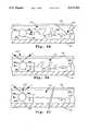
- FIGS. 6A-6Cillustrate the steps in extending a DNA filament, and fixing the filament in its extended condition, in accordance with one embodiment of the invention
- FIG. 7shows a hypothetical plot of filament stretching force as a function of filament length
- FIGS. 8A and 8Billustrate the steps in extending a duplex DNA at a final known stretching force
- FIGS. 9B and 9Cillustrates steps in preparing an extended nucleic acid filament on a substrate, for high resolution microscopy.
- FIGS. 10A and 10Billustrate the use of the method of the invention for restriction fragment mapping in a large genomic fragment.
- FIG. 1is a schematic view of a single-beam optical trap apparatus 10 constructed according to the present invention.
- a modified fluorescence microscope 12 in the apparatusprovides part of the optical train in a single-beam optical trap, and also provides optics for viewing a region of a chamber 14 where particle manipulation takes place, in accordance with the invention.
- the chamberis mounted on a conventional microscope stage 16 which allows positioning in the plane of the stage, and vertical positioning, conventionally.
- a movable light source 18is designed to produce a movable beam 20 of divergent coherent light.
- Source 18includes a adjustable-power laser 22 which outputs a coherent optical beam.
- the lasermay be a visible-light laser, such as an argon ion laser (514 nm), a near infrared diode laser (e.g., 830 nm), or an infrared Nd YAG laser (1.06 ⁇ m).
- the power requirementsare in the range 1 mW to 1 W.
- the laser output beamis directed to a moveable platform 24 in the light source by an optical fiber 26 coupled conventionally to the laser.
- the fiber endis mounted on platform 24, and directs a source beam through a lens system which consists of a microscope objective lens 34 and a diverging lens 36.
- the lens systemfunctions to decrease the divergence of the light out of the fiber.
- Platform 24conventionally includes a pair of micrometers (not shown) for movement in the X-Y plane.
- the divergent light beam from the movable light sourceis reflected by a reflector 38, and the reflected beam is directed at a collimating lens 40 which is mounted on the side of microscope 12.
- Lens 40functions to produce a collimated beam 42 which is directed through an opening 44 in the microscope, and reflected by a dichroic beam splitter 46 toward an objective lens 48 at the bottom of the microscope, as will be described below.
- One suitable collimating lenshas a 2 inch diameter, and a focal length of between about 30-50 cm.
- Lens 48 in the optical train of the trapping beamis a high-numerical aperture objective lens effective to produce a strongly convergent optical beam trap 52 at selected locations within chamber 14, when a beam of collimated light substantially fills the lens, i.e., the back aperture of the objective lens, as will be described below.
- the lensis preferably a liquid-immersion type, and is placed against the chamber as illustrated in FIG. 2 below.
- high numerical apertureis meant a numerical aperture of at least about 0.8 and preferably between about 1.2 or greater.
- Microscope 12includes an optical system 54 for viewing the region of chamber 14 where particle manipulation occurs.
- the viewing systemconventionally includes objective lens 48, a tube lens 58, a microscope eyepiece and an image-intensified video camera 60 or other electro-optical imaging device.
- Illumination for fluorescence microscopyis provided by a fluorescence light source, indicated by arrow 62, whose beam is directed onto lens 48 by a second dichroic beam splitter 64.
- a fluorescence light sourceis an argon laser capable of operation in the UV spectrum or at 488 or 514 nm with power up to 1 watt.
- Illumination for brightfield microscopyis provided by a visible light source, indicated by arrow 66, a mirror 68 and condenser lens 70, as shown.
- FIG. 2is a schematic illustration of the objective lens and stage region of the apparatus.
- the figureshows at 72 the lower end of the lens system for the microscope objective, including objective lens 48.
- Chamber 14 in the figureis formed by a glass slide 74 carried on stage 16, and a coverslip 76 placed over a thin film of liquid on the slide.
- An oil drop 78is placed between the objective lens and coverslip.
- the optical systemis designed to focus the optical trap in the thin-film chamber between the glass slide and coverslip.
- the view regioni.e., the region in which the beam can be manipulated, lies directly below the objective lens in the thin film chamber.
- FIG. 3is a ray diagram which illustrates the physical forces in a single-beam optical trap.
- the light rays of collimated beam 42are strongly converged by lens 48 to a focal region 82 just above the location of particle trapping.
- the diagramshows the scattering of a pair of rays 84 by a dielectric spherical particle 80.
- the rays 86 in the figurerepresent rays which are refracted by the particle, and the rays 87 and 88, surface reflection rays. It can be appreciated from the difference between the angles of rays 84 and 86 that the particle acts as a positive lens.
- the forces indicated at 90 in the figurerepresent the intensity of the gradient force on the particle due to refraction of rays 84 by the particle. This gradient force is proportional to the gradient of the intensity of the refracted rays and points in the direction indicated by vectors 90.
- the net gradient force applied to the particleis sufficient to (a) balance the downward force due to the transfer of momentum to the beam and (b) stabilize the particle axially.
- the light rays which produce particle trappingare also referred to herein as an optical beam trap.
- the ability of the trap to stably trap microscopic particles, especially in the nm range, in the Z directiondepends upon strong lens convergence in the objective lens.
- An additional condition for stagle particle trappingis the requirement that the Boltzman factor exp(-U/kt) ⁇ 1, where U is the potential of the gradient force and is proportional to the square of the beam power (Ashkin).
- exp(-U/kT)the Boltzman factor exp(-U/kt) ⁇ 1
- Uthe potential of the gradient force and is proportional to the square of the beam power
- a 1.0 ⁇ m dielectric spherecan be trapped for tens of minutes at a beam power of a fraction of a mW. Particles of about 0.109 ⁇ m can be stably trapped for 25 seconds at 1 mW power (Ashkin). Trapping over a size range from Rayleigh particles as small as 10 nm, to Mie particles up to 10 ⁇ m in size is practical with the single-beam methods.
- the generally preferred beam poweris one just sufficient to stably trap the particle being examined, since excessive power levels will cause greater beam damage to the particles over time. It is also noted that where Z-direction (vertical) trapping is not required, i.e., where the particle is dragged along the bottom of the view chamber, the particle can be held stably at a much lower gradient force.
- the numerical aperture of the lens for this purposemay accordingly be relatively small, e.g., about 0.6-0.8.
- FIGS. 4A-4Cillustrate the effect of beam width and placement on the position and gradient force of an optical trap formed by a strongly convergent objective lens, such as lens 48.
- the upper portion of each figureshows the Gaussian distribution 91 of beam intensity with respect to a cylindrical surface 92 formed by a vertical projection of the perimeter of the lens.
- FIG. 4Arepresents the case where the beam substantially fills the lens, i.e., where the beam is centered with respect to the lens, and has a significant intensity, e.g., 50% of maximum intensity, at the beam perimeter.
- This configurationproduces a relatively steep, symmetrical gradient force at the optical trap, as is required for efficient particle trapping.
- FIG. 4Bshows the effect of shifting the beam in FIG. 4A laterally with respect to the lens, to shift the position of the optical trap. It can be appreciated that movement away from the centered position reduces the gradient intensity of the focused beam. Thus, the trapping force of the beam decreases proportionally as the beam is moved further away from its central position.
- the collimated beam directed onto the objective lenshas a narrower beam width which does not fill the lens, i.e., the beam intensity at the lens perimeter is quite low.
- the focused optical beamis less steep than in the FIG. 4A configuration, with a corresponding loss of gradient force at the optical trap. It will be appreciated, however, that the gradient force of the beam is not reduced significantly when the collimated beam is shifted away from its central position, since the extent to which the lens is filled is less dependent on beam position.
- the FIG. 4A-4C examplesillustrate the limitations in manipulating an optical trap position by laterally shifting the position of a source on the objective lens.
- FIG. 5is a ray diagram showing how the optical beam trap is moved in the apparatus of the invention, without loss of gradient force at the optical trap.
- the optical path shown in the figureis identical to that shown in FIG. 1, except that reflection from reflector 38 is omitted.
- the solid ray lines in the figureshow the optical rays of a divergent beam 20 from light source 18 positioned along the axes (dash-dot line 92) of collimating lens 40 and objective lens 48.
- the collimating lensproduces a collimated beam 42 which substantially fills the objective lens, as illustrated in FIG. 4A.
- This conditionrequires that the width of the divergent beam at the collimating lens, indicated at W, is such as to fill the objective lens, as illustrated in FIG. 4A.
- the position of the optical trapis indicated at 97.
- the dotted ray lines in the figurerepresent the optical rays produced when source 18 is moved away from its axially aligned position to the position shown in dotted lines at 18'.
- the divergent beam 20A'is now directed against the "upper" portion of the collimated lens, with a width W, similar to width W.
- the collimated lensis constructed and positioned to produce a collimated beam 42, which is directed toward objective lens 48 so as to substantially fill the lens, at an angle ⁇ with respect to the lens axes.
- lens 40functions to (a) shift the angle ⁇ by which the collimated beam is directed against the objected lens, and (b) maintain the position of the collimated beam substantially fixed in the plane of the objected lens, so that the beam fills the lens. This condition applies at all beam angles g within the viewing area of the microscope.
- the apparatusprovides a simple optical configuration which allows an optical beam to ge moved to selected positions in a viewing field, while maintaining beam intensity and intensity gradient properties needed for stable particle trapping.
- the use of the apparatus for manipulating a dielectric particle in a view field, particularly for manipulating a polymer filament to an extended condition,will be described in Section II.
- the apparatusis used, in accordance with another aspect of the invention, for stretching and securing a linear polymer in an extended condition.
- one end of the filamentis coupled to a particle, and the filament and particle are immersed in a film of fluid in a chamber, with the opposite end of the filament anchored to the chamber.
- the particleis trapped in the fluid by an optical trap formed as in Section I, and the trap is manipulated until the filament is in an extended condition.
- FIGS. 6A-6Cillustrate the particle manipulation method of the invention, as applied to manipulating a filament of DNA.
- Each figureshows a portion of a chamber 14 containing a filament 95 and filament-end particles 98, 100 suspended in a fluid film 102 between a glass slide 74 and a coverslip 76, as in FIG. 2.
- the fluid filmis an viscous aqueous polymer solution, such as a solution containing 1-2 weight percent polyethylene glycol or methylcellulose. The viscosity of the solution is effective to quench the Brownian motion of large molecules, such as the DNA filament.
- the filamentis double-stranded DNA.
- the filamentmay be single-stranded DNA or RNA, or chromosome or chromosome-fragment filaments. Chromosomes and DNA and RNA filaments of selected sizes can be isolated and, optionally fragmented and/or sized according to well-known methods.
- particles 98, 100are amine-coated particles which can ge coupled covalently to the 5'-end phosphate groups of nucleic acid filaments through phosphoamidate bonds, as shown for particle 98 in FIGS. 5B and 5C (Particle 100 is similarly coupled to the 5' phosphate of the opposite strand of the duplex filament).
- Suitable particlesare amine-coated polystyrene beads, 0.5-1.0 ⁇ m supplied by Polysciences, Inc. (Warrington, Pa.). The particles are coupled to the beads in the presence of a water-soluble carbodiimide, under standard coupling conditions.
- the concentration of filaments in the filmis about 10 9 molecules/cc, each with beads coupled to its ends.
- the beadsmay be coupled to small stick-end or blunt-end duplex fragments which can then be ligated to the filament of interest by known ligation methods.
- This approachallows specific attachment of filaments whose ends have the complementary sticky end sequence as the fragments attached to the particles.
- the filament endsare coupled to particles by ligand/anti-ligand binding.
- the opposite ends of a nucleic acid filamentare biotinylated, for example, by ligation to a biotinylated linker, or by nick translation in the presence of biotinylated deoxynucleoside triphosphosphates, according to known methods (Wilchek).
- the filamentsare allowed to react with avidin or streptavidin-coated beads, such as are available commercially, e.g., from Polysciences, Inc. to form high-affinity binding of the filament ends to the particles.
- one of the particlesis fastened to the bottom of the slide.
- Thiscan be done readily, in accordance with one aspect of the invention, by capturing the particle in the optical trap, indicated at 110 in FIG. 6B, and with the particle positioned near surface of the slide, optically adhering the bead to the slide surface, as shown in the figure.
- Optical adheringis done by holding the captured particle against the chamber until the portion of the particle in contact with the chamber melts under the laser heat at the optical trap.
- thermopolymerssuch as polyethylene, latex, or nylon may be similarly attached to the chamber, to anchor one end of the filament.
- particle 98is captured in the optical beam and manipulated to move the particle toward an extended condition. Since double-stranded DNA normally exists in a coiled, somewhat globular form, the molecule will rapidly unwind as it is being stretched. According to an important advantage of the present method, the particle is allowed to rotate in the trap without affecting the forces which provide trapping stability. That is, no torques are applied to the molecule as it is stretched.
- the optical trapis moved in this fashion until the filament is extended, as illustrated in FIG. 6C, and preferably until a preselected stretching force exerted on the filament is reached, as will be described with reference to FIGS. 7 and 8. At this position, the "free" particle is optically adhered to the chamber as above, to fix the filament in its extended condition.
- the filament mediummay also include topoisomerase enzyme(s) to remove knots in the filament as it is being stretched.
- the trapping force necessary to maintain the particle in a trapped conditionmust be greater than the force exerted by the molecule in resisting stretching.
- An important advantage of the inventionis that the trapping force on the particle is relatively invariant as the trap is manipulated in the view field, as discussed in Section I, and this reduces the tendency of the particle to escape from the trap as the beam is moved and stretching forces are applied to the particle.
- the optical trap force characteristicsmake it possible to extend the filament with a selected stretching force.
- This approachrequires first measuring the trapping force of the trap as a function of beam power, using a flow-cell configuration for the particle chamber.
- a spherical particle of a given radius ris captured in the optical trap and the flow velocity of a liquid medium sufficient to dislodge the particle from the trap is measured at each of a number of power levels. From these measurements, the trapping force of the beam as a function of beam power can be determined.
- the force required to stretch a polymer filamentcan now be plotted as a function of stretching distance, i.e., the particle-to-particle extended length of the filament. This is done by first capturing the free particle end of the tethered filament in an optical trap, at a laser power corresponding to a relatively low trapping force. The particle is then manipulated to stretch the filament, until the filament stretching force pulls the particle from the trap, and the distance between the two particles is recorded. The procedure is repeated at increasing trapping forces (laser power levels), and the observed distances at each power level are recorded.
- FIG. 7shows a hypothetical plot of duplex DNA stretch distance as a function of stretching force.
- the relatively flat portion of the curvecorresponds to initial uncoiling of the filament as it assumes a less globular conformation.
- the intermediate, steeper portion of therepresents the increased stretching force as the filament is stretched from an uncoiled, but irregular, conformation to a substantially straight, extended conformation. Beyond this, additional stretching is accommodating by changes in the dihedral angles of the filament backbone bonds, in directions which lengthen the backbone, and this stretching is accomplished only at a considerable cost in stretching force, as indicated by the steepest portion of the curve.
- the filamentwill be stretched with a force sufficient to extend the filament close to the elbow in the curve where bond stretching occurs, i.e., where the filament is in a relatively straight, extended condition.
- the observed distances along the length of the filamentcan then be calibrated, using filaments of known basepair length, for standardized distance measurements along filaments in an extended form.
- FIGS. 8A and 8BThe steps in manipulating a DNA filament in an extended form, with a selected stretching force, are illustrated in FIGS. 8A and 8B, where the filament and particles have the same numbers as in FIGS. 6A-6C.
- FIG. 8Ashows the manipulated-particle end of the filament being moved away from its opposite end in an optical trap 110 having a laser power level corresponding to a selected stretching force.
- the beam positionis one at which the particle is just being pulled from the optical trap. This position, indicated by arrow 11, corresponds to a desired level of filament stretching, and the location is marked, either in relation to crosshairs in the chamber, or by the caliper settings of the platform used for beam movement.
- the escaped particleis then recaptured, as shown in FIG. 8B, and returned to the site just preceding the position of particle escape.
- the particleis then glued at this position by fusing, as above.
- the filamentis now stably fixed on the slide under a selected stretching force, allowing the distances along the filament length to be reproducibly determined and calibrated in terms of numbers of basepairs.
- the extended filamentmay be used to examine a variety of filament binding and kinetic events in real time, as will be described in Section III with respect to nucleic acid filaments.
- a stretched DNA filamentis examined by high-magnification fluorescence microscopy.
- the precision of locating a fluorescent reporter molecule on the filament, using digital analysis of the image recorded by the image-intensified video camera to analyze the intensity distribution of fluorescence emitted by the molecule,is about 10-30 nm, corresponding to about 30-100 basepairs. It is noted that this precision is substantially better than the distance resolution, defined by the ability to resolve two closely spaced signals, which is achievable by fluorescence microscopy.
- a variety of fluorescent DNA-intercalating dyesmay be employed for visualizing duplex DNA.
- the duplex filamentis labeled with the dye conventionally, and unbound dye can be removed by washing.
- the dye reporterallows the DNA filament to be seen as a fine strand under fluorescence microscopy.
- the intensity of the dyei.e., the density of dye in the filament, can be selectively reduced by addition of particles, such as polystyrene particles, which compete with DNA for binding to ethidium bromide.
- the filamentcan be densely labeled during the filament extension operation, to permit easy visualization of the extended molecule. Thereafter, for examining any reactions of molecules with the filament, the staining dye can be removed so that the dye will not interfere with these reactions. Also removal of the dye may be necessary for contrast enhancement, in order to visualize fluorescent-labeled molecules bound to the extended filament.
- the binding moleculecan be labeled with a reporter having a different fluorescence absorption peak, allowing the second reporter to be visualized at a second excitation wavelength.
- Fluorescent-labeled probes suitable for labeling probes, enzymes and or particlesare well known.
- the illumination sourceis preferably a pulsed laser which can be operated at high power levels over timed pulsed intervals as short as 10 -12 to 10 -9 seconds. As discussed above, the fluorescence from the reporter is observed only in the interval between excitation pulses, to eliminate background Raman scattering.
- the extended DNA filamentcan be examined by nanometer-scale probe microscopy, scanning tunnelling microscopy (e.g., Dunlap, Williams), or dehydrated and examined by conventional or scanning electron microscopy.
- FIGS. 9A and 9Billustrate a method for examining extended nucleic acid filaments on a substrate in a dehydrated form.
- a nucleic acid filament 130is extended and fixed in the liquid film in the chamber, as above, over a substrate 132 in the chamber, indicated at 134 in FIG. 9A.
- the filament in solutionmay be contacted with a selected binding molecule, such as sequence-specific oliogonucleotide probes, binding proteins, enzymes, histone proteins, ribosomal particles or the like, as described in Section III below, to bind the agent at a site on the filament.
- the chamberis then drained and the filament is allowed to dry, in its extended form, on the substrate, as shown in top view in FIG. 9B.
- the filamentcan be stained with conventional tungstate salts or the like.
- the filamentmay be metalized, or examined directly.
- the advantages of the polymer manipulation method of the inventioncan be appreciated from the foregoing.
- the methodfacilitates particle manipulation by maintaining a relatively constant trapping force on the particle as the particle is moved in the view field.
- the particlecan be manipulated within the view field at a selected trapping force, and extended to a length corresponding to a known, selected stretching force.
- Thisprovides a standard measure of polymer length, in the extended-filament condition, which can be calibrated in terms of number of polymer subunits.
- the methodalso provides a simple method for attaching the ends of a stretched filament to the chamber, using the optical trap to adhere the particles at the filament ends to the chamber.
- the methodcan be used to extend extremely large nucleic acid fragments, such as genomic fragments in the 1-10 megabasepair size range or larger. Fragments of this size are quite fragile and previous methods for physically extending the fragments have generally been unsuccessful, due to the inability to control the stretching force applied to the filament.
- the stretching force exerted on the filamentis never greater than the trapping force exerted on the filament-coupled particle, and this force can be selected to ensure that the filament is not broken as it is extended.
- the inventionincludes a method of nucleic acid filament preparation, for examining the filament in an extended condition.
- the filamentis contacted with a sequence-dependent binding molecule, and the binding site(s) in the extended filament are localized by determining the distance from a site from the ends of the filaments, or from one another.
- the filamentis a 1-10 megabasepair genomic duplex fragment having rare restriction sites S n spaced at intervals having an average spacing, for example of 100-1,000 kilobases.
- rare restriction sitesare XhoI, with an average spacing between sites of about 200 kbases, SfiI and MluI, with an average spacing of about 500 kbases, and NotI, with an average spacing of about 1,000 kilobases.
- genomic fragmentsare prepared according to known methods. Where, as here, it is desired to extend an entire chromosomal DNA, isolation must be done with a minimum of disruptive handling procedures.
- chromosomal DNAcan be isolated from a cell by treating the cell with proteases and cell disruptive agents to release the chromosomal DNA, which is then drawn into an agarose slab and fractionated by agarose electrophoresis. The selected fragment may be eluted by electrophoresis into a receiving chamber which becomes the viewing chamber where particle attachment to the filament(s) and particle manipulation are carried out.
- the genomic filamentsare suspended in a standard coupling buffer and the fragment ends are coupled to amine-coated beads, such as beads 142, 144 coupled to fragment 140.
- the bufferis then replace by a standard hybridization buffer containing 1% by weight methylcellulose (50-100 kdaltons), at a fragment concentration of about 10 9 filaments/cc, as above.
- a fluorescent-labeled probesuch as DNA probe 146, which is complementary to the selected rare restriction site sequences, such as the NotI sites in the fragments.
- the probesare mixed with the duplex fragments under partial denaturation conditions which allow probe hybridization with the duplex fragment, according to known methods. Alternatively, the probes may be hybridized to the duplex by RecA-catalyzed D-loop formation. Fluorescent-labeled probes are prepared conventionally.
- the desired fragmentmay be identified by its binding to a fluorescently-labeled probe 148 specific to the known region, but distinguishable from the restriction-site probes on the basis of a different emission or absorption characteristics.
- the fragment of interestis manipulated to an extended condition, preferably corresponding to a selected stretching force, as above, and the particles are attached to the chamber surface, as by optical adherence.
- the extended filamentis now examined to determine the distance between fluorescent-labeled restriction-site probes, typically by measuring the distances between probe sites seen in the video camera images.
- the fragmentcontains six rare restriction sequences s 1 -s 6 which define five restriction segments f 1 -f 6 , with the relative measured lengths shown in the figure. The distances between each of the restriction sites and known sequence A are also recorded.
- FIG. 10Bshows an enlargement of segment f 5 , with probes specific to the more frequent restriction site being bound at sites s 5-1 to s 5-5 between previously identified sites s 5 and s 6 .
- the seven restriction sitesdefine six subsegments f 5-1 to f 5-6 in segment f 5 , as indicated. The lengths of these subsegments are determined as above.
- a more detailed restriction mapmay be constructed in this manner by addition of probes specific to other restriction sites.
- the identified segmentsmay be isolated at any stage by restriction site digestion and fractionation by electrophoresis, according to standard procedures. For example, following the two-probe analysis above, genomic fragments may be digested to completion with the rare cutter restriction enzyme, e.g., NotI, and subfragments having the expected segment size, e.g., of fragment f 5 , then isolated from the gel. These subfragments may be further digested to completion with the second, more frequent restriction enzyme, and the smaller subfragments again fractionated by gel electrophoresis. Smaller subfragments, e.g., f 5-4 , are identified on the gel by their known size and isolated. These isolated fragments can now be cloned for sequencing, and/or expression, or further analyzed by the mapping method just described.
- the rare cutter restriction enzymee.g., NotI
- subfragments having the expected segment sizee.g., of fragment f 5
- the filamentcan be suitably prepared for electron microscopy or force field microscopy.
- sequence-specific binding moleculessuch as restriction enzymes, enhancers, repressors, transcriptional or translational initiation or termination factors, histones, and ribosomes may be substituted for nucleic acid probes, for localization of binding sites on an extended filament.
- DNA-binding agentscan be fluorescent labeled by known methods of derivatizing proteins with fluorescent reporters.
- the extended filamentserves as a substrate for nucleic-acid specific enzymes or ribosomes, for real-time measurements of the rate and/or mechanism of interaction of enzymes or ribosomes with extended DNA.
- filaments of mRNAare prepared by known methods, coupled at opposite ends to particles, and extended by the optical trap manipulation methods described above. With the mRNA in an extended condition, in vitro translation components are added to the liquid film.
- the determinations which can be made in the methodare (i) the time sequence in which the ribosomes become attached to the mRNA filament; (ii) the rate of movement along the filament; and (iii) the fate of the ribosomes in the presence of various translation inhibitors, i.e., whether the inhibitor stops ribosome movement along the strand or causes the ribosomes to detach from the mRNA.
- the methodmay similarly be used to study the mechanisms and kinetics of attachment and movement of RNA or DNA polymerases, reverse transcriptases, reverse topoisomerases (in a pair of crossed, extended filaments) and repair enzyme along an extended DNA filament, employing fluorescently-labeled enzymes.
Landscapes
- Physics & Mathematics (AREA)
- Spectroscopy & Molecular Physics (AREA)
- Electromagnetism (AREA)
- Engineering & Computer Science (AREA)
- Plasma & Fusion (AREA)
- Investigating, Analyzing Materials By Fluorescence Or Luminescence (AREA)
- Measuring Or Testing Involving Enzymes Or Micro-Organisms (AREA)
Abstract
Description
Claims (16)
Priority Applications (1)
| Application Number | Priority Date | Filing Date | Title |
|---|---|---|---|
| US07/528,316US5079169A (en) | 1990-05-22 | 1990-05-22 | Method for optically manipulating polymer filaments |
Applications Claiming Priority (1)
| Application Number | Priority Date | Filing Date | Title |
|---|---|---|---|
| US07/528,316US5079169A (en) | 1990-05-22 | 1990-05-22 | Method for optically manipulating polymer filaments |
Publications (1)
| Publication Number | Publication Date |
|---|---|
| US5079169Atrue US5079169A (en) | 1992-01-07 |
Family
ID=24105172
Family Applications (1)
| Application Number | Title | Priority Date | Filing Date |
|---|---|---|---|
| US07/528,316Expired - LifetimeUS5079169A (en) | 1990-05-22 | 1990-05-22 | Method for optically manipulating polymer filaments |
Country Status (1)
| Country | Link |
|---|---|
| US (1) | US5079169A (en) |
Cited By (87)
| Publication number | Priority date | Publication date | Assignee | Title |
|---|---|---|---|---|
| US5356776A (en)* | 1991-09-10 | 1994-10-18 | Hitachi, Ltd. | DNA measuring method |
| US5512745A (en)* | 1994-03-09 | 1996-04-30 | Board Of Trustees Of The Leland Stanford Jr. University | Optical trap system and method |
| WO1996039417A1 (en)* | 1995-06-05 | 1996-12-12 | Seq, Ltd. | Chemical, biochemical and biological processing in thin films |
| WO1996041154A1 (en)* | 1995-06-07 | 1996-12-19 | UNITED STATES GOVERNMENT, as represented by THE SECRETARY OF COMMERCE NATIONAL INSTITUTE OF STANDARDS AND TECHNOLOGY | Optical trap for detection and quantitations of subzeptomolar quantities of analytes |
| US5674743A (en)* | 1993-02-01 | 1997-10-07 | Seq, Ltd. | Methods and apparatus for DNA sequencing |
| US5720928A (en)* | 1988-09-15 | 1998-02-24 | New York University | Image processing and analysis of individual nucleic acid molecules |
| US5840862A (en)* | 1994-02-11 | 1998-11-24 | Institut Pasteur | Process for aligning, adhering and stretching nucleic acid strands on a support surface by passage through a meniscus |
| DE19742227A1 (en)* | 1997-09-25 | 1999-04-01 | Juergen Prof Dipl Phys Wolfrum | Method of sequencing a single DNA molecule |
| US6055106A (en)* | 1998-02-03 | 2000-04-25 | Arch Development Corporation | Apparatus for applying optical gradient forces |
| US6147198A (en)* | 1988-09-15 | 2000-11-14 | New York University | Methods and compositions for the manipulation and characterization of individual nucleic acid molecules |
| DE19929530A1 (en)* | 1999-06-28 | 2001-01-04 | Alexander Cherkasky | Rapid sequencing of genomes, comprises determining a genomic DNA sequence continuously without fragmenting the DNA |
| US6180940B1 (en) | 1998-04-07 | 2001-01-30 | Universite Laval | Light-driven molecular rotational motor |
| US6210896B1 (en) | 1998-08-13 | 2001-04-03 | Us Genomics | Molecular motors |
| US6221592B1 (en) | 1998-10-20 | 2001-04-24 | Wisconsin Alumi Research Foundation | Computer-based methods and systems for sequencing of individual nucleic acid molecules |
| US6248537B1 (en) | 1999-05-28 | 2001-06-19 | Institut Pasteur | Use of the combing process for the identification of DNA origins of replication |
| EP1059871A4 (en)* | 1998-03-04 | 2001-08-01 | Board Or Regents The Universit | Optical stretcher |
| WO2001063259A1 (en)* | 2000-02-22 | 2001-08-30 | Carl Zeiss Jena Gmbh | Method and system for detecting the light coming from a sample |
| US6344319B1 (en)* | 1996-10-30 | 2002-02-05 | Institut Pasteur | Method for diagnosis of genetic diseases by molecular combing and diagnosis box |
| US6355420B1 (en) | 1997-02-12 | 2002-03-12 | Us Genomics | Methods and products for analyzing polymers |
| US6403311B1 (en) | 1997-02-12 | 2002-06-11 | Us Genomics | Methods of analyzing polymers using ordered label strategies |
| US20020081744A1 (en)* | 1999-08-13 | 2002-06-27 | Chan Eugene Y. | Methods and apparatuses for characterization of single polymers |
| US20020115164A1 (en)* | 2000-11-13 | 2002-08-22 | Genoptix | Methods and apparatus for generating and utilizing a moving optical gradient |
| US20020123112A1 (en)* | 2000-11-13 | 2002-09-05 | Genoptix | Methods for increasing detection sensitivity in optical dielectric sorting systems |
| US20020132316A1 (en)* | 2000-11-13 | 2002-09-19 | Genoptix | Methods and apparatus for sorting of bioparticles based upon optical spectral signature |
| US20020160470A1 (en)* | 2000-11-13 | 2002-10-31 | Genoptix | Methods and apparatus for generating and utilizing linear moving optical gradients |
| WO2002077259A3 (en)* | 2001-03-24 | 2002-11-14 | Aviva Biosciences Corp | Biochips including ion transport detecting structures and methods of use |
| US20030008364A1 (en)* | 2001-04-27 | 2003-01-09 | Genoptix | Method and apparatus for separation of particles |
| WO2003018299A1 (en)* | 2001-08-31 | 2003-03-06 | Arryx, Inc. | Optical tools manipulated by optical traps |
| US20030109040A1 (en)* | 2001-11-14 | 2003-06-12 | Josef Kas | Optical cell guidance method and apparatus |
| US20030111594A1 (en)* | 2001-12-13 | 2003-06-19 | Commissariat A L'energie Atomique | Optical device and optical process for particle displacement |
| US6607888B2 (en) | 1998-10-20 | 2003-08-19 | Wisconsin Alumni Research Foundation | Method for analyzing nucleic acid reactions |
| US6610256B2 (en) | 1989-04-05 | 2003-08-26 | Wisconsin Alumni Research Foundation | Image processing and analysis of individual nucleic acid molecules |
| US20030165964A1 (en)* | 2001-08-27 | 2003-09-04 | Hannah Eric C. | Electron induced fluorescent method for nucleic acid sequencing |
| US6626546B2 (en)* | 2001-04-27 | 2003-09-30 | University Of Chicago | Apparatus for using optical tweezers to manipulate materials |
| US20030186426A1 (en)* | 2000-03-15 | 2003-10-02 | The Regents Of The University Of California | Multichannel flow cell for interacting single optically trapped, DNA molecules with different chemical species |
| US20030194755A1 (en)* | 2001-04-27 | 2003-10-16 | Genoptix, Inc. | Early detection of apoptotic events and apoptosis using optophoretic analysis |
| US20030193984A1 (en)* | 2000-07-26 | 2003-10-16 | Mihrimah Ozkan | Manipulation of live cells and inorganic objects with optical micro beam arrays |
| US20030211461A1 (en)* | 2002-05-01 | 2003-11-13 | Genoptix, Inc | Optophoretic detection of durgs exhibiting inhibitory effect on Bcr-Abl positive tumor cells |
| US20040009540A1 (en)* | 2001-04-27 | 2004-01-15 | Genoptix, Inc | Detection and evaluation of cancer cells using optophoretic analysis |
| US20040021949A1 (en)* | 2002-08-01 | 2004-02-05 | The University Of Chicago | Apparatus and method for fabricating, sorting, and integrating materials with holographic optical traps |
| US20040033539A1 (en)* | 2002-05-01 | 2004-02-19 | Genoptix, Inc | Method of using optical interrogation to determine a biological property of a cell or population of cells |
| US6696022B1 (en) | 1999-08-13 | 2004-02-24 | U.S. Genomics, Inc. | Methods and apparatuses for stretching polymers |
| US20040053209A1 (en)* | 2002-09-12 | 2004-03-18 | Genoptix, Inc | Detection and evaluation of topoisomerase inhibitors using optophoretic analysis |
| WO2004026458A1 (en)* | 2002-09-17 | 2004-04-01 | Humboldt Universität Zu Berlin | Method for arranging a polymer molecule |
| US6718083B2 (en) | 2001-06-20 | 2004-04-06 | Arryx, Inc. | Optical switch and router |
| US20040067167A1 (en)* | 2002-10-08 | 2004-04-08 | Genoptix, Inc. | Methods and apparatus for optophoretic diagnosis of cells and particles |
| US6744038B2 (en) | 2000-11-13 | 2004-06-01 | Genoptix, Inc. | Methods of separating particles using an optical gradient |
| US20040121307A1 (en)* | 2002-12-19 | 2004-06-24 | Genoptix, Inc | Early detection of cellular differentiation using optophoresis |
| US20040121474A1 (en)* | 2002-12-19 | 2004-06-24 | Genoptix, Inc | Detection and evaluation of chemically-mediated and ligand-mediated t-cell activation using optophoretic analysis |
| US6759235B2 (en) | 2000-04-06 | 2004-07-06 | Quantum Dot Corporation | Two-dimensional spectral imaging system |
| US20040146849A1 (en)* | 2002-01-24 | 2004-07-29 | Mingxian Huang | Biochips including ion transport detecting structures and methods of use |
| US6778724B2 (en) | 2000-11-28 | 2004-08-17 | The Regents Of The University Of California | Optical switching and sorting of biological samples and microparticles transported in a micro-fluidic device, including integrated bio-chip devices |
| US20040209355A1 (en)* | 1996-12-06 | 2004-10-21 | Nanogen, Inc. | Systems and devices for photoelectrophoretic transport and hybridization of oligonucleotides |
| US20050009004A1 (en)* | 2002-05-04 | 2005-01-13 | Jia Xu | Apparatus including ion transport detecting structures and methods of use |
| US20050058990A1 (en)* | 2001-03-24 | 2005-03-17 | Antonio Guia | Biochip devices for ion transport measurement, methods of manufacture, and methods of use |
| US20050082204A1 (en)* | 1995-04-03 | 2005-04-21 | Schwartz David C. | Micro-channel long molecule manipulation system |
| US20050081824A1 (en)* | 2003-10-20 | 2005-04-21 | Taiwan Semiconductor Manufacturing Co. | Contaminant particle removal by optical tweezers |
| US20050094232A1 (en)* | 2000-11-13 | 2005-05-05 | Genoptix, Inc. | System and method for separating micro-particles |
| US20050146718A1 (en)* | 2003-09-19 | 2005-07-07 | Bustamante Carlos J. | Light-force sensor and method for measuring axial optical-trap forces from changes in light momentum along an optic axis |
| US20050147373A1 (en)* | 2003-12-24 | 2005-07-07 | Yuegang Zhang | Controlling carbon nanotubes using optical traps |
| US6927065B2 (en) | 1999-08-13 | 2005-08-09 | U.S. Genomics, Inc. | Methods and apparatus for characterization of single polymers |
| US20050196614A1 (en)* | 2004-03-02 | 2005-09-08 | Jan Weber | Apparatus and method for coating objects using an optical system |
| US20050196746A1 (en)* | 2001-03-24 | 2005-09-08 | Jia Xu | High-density ion transport measurement biochip devices and methods |
| US20050207940A1 (en)* | 2003-08-28 | 2005-09-22 | Butler William F | Methods and apparatus for sorting cells using an optical switch in a microfluidic channel network |
| US20050208557A1 (en)* | 1999-05-19 | 2005-09-22 | Jonas Korlach | Uses of terminal-phosphate-labeled nucleotides |
| US20050266478A1 (en)* | 2002-01-24 | 2005-12-01 | Mingxian Huang | Biochips including ion transport detecting structures and methods of use |
| US20060029955A1 (en)* | 2001-03-24 | 2006-02-09 | Antonio Guia | High-density ion transport measurement biochip devices and methods |
| US20060088944A1 (en)* | 1995-04-03 | 2006-04-27 | Schwartz David C | Micro fluidic system for single molecule imaging |
| DE19937512B4 (en)* | 1999-08-09 | 2006-08-24 | Alexander Cherkasky | Method and apparatus for rapid genome sequencing by linearization or separation of the DNA |
| US20070009909A1 (en)* | 2005-06-30 | 2007-01-11 | Lopez Herman A | Sorting of carbon nanotubes through arrays |
| EP1635160A3 (en)* | 2004-09-10 | 2007-02-07 | Agilent Technologies, Inc. | Nanostepper/sensor systems and methods of use thereof |
| JP2007136568A (en)* | 2005-11-15 | 2007-06-07 | National Institute Of Advanced Industrial & Technology | Cutting method and cutting apparatus for minimal linear flexible object |
| US20070172860A1 (en)* | 2000-12-01 | 2007-07-26 | Hardin Susan H | Enzymatic nucleic acid synthesis: compositions and methods |
| US20070284516A1 (en)* | 2003-09-19 | 2007-12-13 | Bustamante Carlos J | Optical trap utilizing a pivoting optical fiber |
| US20080067111A1 (en)* | 2004-10-01 | 2008-03-20 | Yuegang Zhang | Application of static light to a fluid flow of CNTs for purposes of sorting the CNTs |
| EP1914238A2 (en) | 1995-04-03 | 2008-04-23 | New York University | Methods for measuring physical characteristics of nucleic acids by microscope imaging |
| US20100235105A1 (en)* | 2001-07-09 | 2010-09-16 | Life Technologies Corporation | Method for analyzing dynamic detectable events at the single molecule level |
| US20110171634A1 (en)* | 2008-06-30 | 2011-07-14 | Bionanomatrix, Inc. | Methods and devices for single-molecule whole genome analysis |
| CN102023379B (en)* | 2009-09-17 | 2012-07-25 | 中国科学院物理研究所 | Three-dimensional optical tweezers system |
| WO2013051932A1 (en)* | 2011-10-03 | 2013-04-11 | Vereniging Voor Christelijk Hoger Onderwijs,Wetenschappelijk Onderzoek En Patiëntenzorg | Molecular manipulation apparatus and method for investigating a plurality of molecules |
| US9028776B2 (en) | 2012-04-18 | 2015-05-12 | Toxic Report Llc | Device for stretching a polymer in a fluid sample |
| US9181578B2 (en) | 2008-11-18 | 2015-11-10 | Bionano Genomics, Inc. | Polynucleotide mapping and sequencing |
| US20160032281A1 (en)* | 2014-07-31 | 2016-02-04 | Fei Company | Functionalized grids for locating and imaging biological specimens and methods of using the same |
| US9310376B2 (en) | 2007-03-28 | 2016-04-12 | Bionano Genomics, Inc. | Methods of macromolecular analysis using nanochannel arrays |
| US9845238B2 (en) | 2006-07-19 | 2017-12-19 | Bionano Genomics, Inc. | Nanonozzle device arrays: their preparation and use for macromolecular analysis |
| US20190383963A1 (en)* | 2017-01-20 | 2019-12-19 | Tokyo Electron Limited | Foreign substance detection device, foreign substance detection method and recording medium |
| EP4617380A1 (en)* | 2024-03-15 | 2025-09-17 | Sogang University Research & Business Development Foundation | Method for scanning electron microscopy (sem)-based optical dna mapping |
Citations (8)
| Publication number | Priority date | Publication date | Assignee | Title |
|---|---|---|---|---|
| US3710279A (en)* | 1969-12-15 | 1973-01-09 | Bell Telephone Labor Inc | Apparatuses for trapping and accelerating neutral particles |
| US3808550A (en)* | 1969-12-15 | 1974-04-30 | Bell Telephone Labor Inc | Apparatuses for trapping and accelerating neutral particles |
| US3808432A (en)* | 1970-06-04 | 1974-04-30 | Bell Telephone Labor Inc | Neutral particle accelerator utilizing radiation pressure |
| US4327288A (en)* | 1980-09-29 | 1982-04-27 | Bell Telephone Laboratories, Incorporated | Method for focusing neutral atoms, molecules and ions |
| US4818681A (en)* | 1985-02-22 | 1989-04-04 | Molecular Diagnostics, Inc. | Fast and specific immobilization of nucleic acids to solid supports |
| US4893886A (en)* | 1987-09-17 | 1990-01-16 | American Telephone And Telegraph Company | Non-destructive optical trap for biological particles and method of doing same |
| US4897444A (en)* | 1985-05-31 | 1990-01-30 | The Research Foundation Of The State University Of New York | Immobilized fluorogenic substrates for enzymes; and processes for their preparation |
| US4939360A (en)* | 1988-02-26 | 1990-07-03 | Hitachi, Ltd. | Particle beam irradiating apparatus having charge suppressing device which applies a bias voltage between a change suppressing particle beam source and the specimen |
- 1990
- 1990-05-22USUS07/528,316patent/US5079169A/ennot_activeExpired - Lifetime
Patent Citations (8)
| Publication number | Priority date | Publication date | Assignee | Title |
|---|---|---|---|---|
| US3710279A (en)* | 1969-12-15 | 1973-01-09 | Bell Telephone Labor Inc | Apparatuses for trapping and accelerating neutral particles |
| US3808550A (en)* | 1969-12-15 | 1974-04-30 | Bell Telephone Labor Inc | Apparatuses for trapping and accelerating neutral particles |
| US3808432A (en)* | 1970-06-04 | 1974-04-30 | Bell Telephone Labor Inc | Neutral particle accelerator utilizing radiation pressure |
| US4327288A (en)* | 1980-09-29 | 1982-04-27 | Bell Telephone Laboratories, Incorporated | Method for focusing neutral atoms, molecules and ions |
| US4818681A (en)* | 1985-02-22 | 1989-04-04 | Molecular Diagnostics, Inc. | Fast and specific immobilization of nucleic acids to solid supports |
| US4897444A (en)* | 1985-05-31 | 1990-01-30 | The Research Foundation Of The State University Of New York | Immobilized fluorogenic substrates for enzymes; and processes for their preparation |
| US4893886A (en)* | 1987-09-17 | 1990-01-16 | American Telephone And Telegraph Company | Non-destructive optical trap for biological particles and method of doing same |
| US4939360A (en)* | 1988-02-26 | 1990-07-03 | Hitachi, Ltd. | Particle beam irradiating apparatus having charge suppressing device which applies a bias voltage between a change suppressing particle beam source and the specimen |
Non-Patent Citations (50)
| Title |
|---|
| Ashkin, A. "Trapping of Atoms by Resonance Radiation Pressure," Phys. Rev. Lett., vol. 40, No. 12 (1978). |
| Ashkin, A. et al., "Internal cell manipulation using infrared laser traps", Proc. Natl. Acad. Sci. USA, 86:7914-7918 (10/89). |
| Ashkin, A. et al., "Observation of a single-bead gradient force optical trap for dielectric particles," Optics letters, 11:288 (5/86). |
| Ashkin, A. et al., "Observation of light scattering from nonspherical particles using optical levitation," App. Optics, 19:5 (3/80). |
| Ashkin, A. et al., "Observation of Radiation-Pressure Trapping of Particles by Alternating Light Beams," 54:12 (3/85). |
| Ashkin, A. et al., "Optical Levitation by Radiation Pressure," App. Phys. Lett., 19:8 (10/71). |
| Ashkin, A. et al., "Optical trapping and manipulation of single cells using infrared laser beams," Nature, 330:24/31 (12/87). |
| Ashkin, A. et al., "Optical Trapping and Manipulation of Single Living Cells Using Infra-Red Laser Beams", Ber Bunsenges Phys. Chem., 93:254-260 (1989). |
| Ashkin, A. et al., "Optical Trapping and Manipulation of Viruses and Bacteria," Science, 235:1517 (3/87). |
| Ashkin, A. et al., "Stability of radiation-pressure particle traps: an optical Earnshaw theorem," Optics Letters, 8:10 (10/83). |
| Ashkin, A. et al., Internal cell manipulation using infrared laser traps , Proc. Natl. Acad. Sci. USA, 86:7914 7918 (10/89).* |
| Ashkin, A. et al., Observation of a single bead gradient force optical trap for dielectric particles, Optics letters, 11:288 (5/86).* |
| Ashkin, A. et al., Observation of light scattering from nonspherical particles using optical levitation, App. Optics, 19:5 (3/80).* |
| Ashkin, A. et al., Observation of Radiation Pressure Trapping of Particles by Alternating Light Beams, 54:12 (3/85).* |
| Ashkin, A. et al., Optical Levitation by Radiation Pressure, App. Phys. Lett., 19:8 (10/71).* |
| Ashkin, A. et al., Optical trapping and manipulation of single cells using infrared laser beams, Nature, 330:24/31 (12/87).* |
| Ashkin, A. et al., Optical Trapping and Manipulation of Single Living Cells Using Infra Red Laser Beams , Ber Bunsenges Phys. Chem., 93:254 260 (1989).* |
| Ashkin, A. et al., Optical Trapping and Manipulation of Viruses and Bacteria, Science, 235:1517 (3/87).* |
| Ashkin, A. et al., Stability of radiation pressure particle traps: an optical Earnshaw theorem, Optics Letters, 8:10 (10/83).* |
| Ashkin, A. Trapping of Atoms by Resonance Radiation Pressure, Phys. Rev. Lett., vol. 40, No. 12 (1978).* |
| Ashkin, A., "Acceleration and Trapping of Particles by Radiation Pressure," Phys. Rev. Lett., vol. 24, No. 4 (1970). |
| Ashkin, A., "Applications of Laser Radiation Pressure," Science, vol. 210, No. 4474 (1980). |
| Ashkin, A., Acceleration and Trapping of Particles by Radiation Pressure, Phys. Rev. Lett., vol. 24, No. 4 (1970).* |
| Ashkin, A., Applications of Laser Radiation Pressure, Science, vol. 210, No. 4474 (1980).* |
| Berns et al., "Use of a laser-induced optical force trap to study chromosome movement of the mitotic spindle," Proc. Natl. Acad. Sci. USA, 86:4539-5453 (6/89). |
| Berns et al., Use of a laser induced optical force trap to study chromosome movement of the mitotic spindle, Proc. Natl. Acad. Sci. USA, 86:4539 5453 (6/89).* |
| Bjorkholm, J. E. et al., "Observation of Focusing of Neutral Atoms by the Dipole Forces of Resonance-Radiation Pressure," Phys. Rev. Lett., 41:20 (11/78). |
| Bjorkholm, J. E. et al., Observation of Focusing of Neutral Atoms by the Dipole Forces of Resonance Radiation Pressure, Phys. Rev. Lett., 41:20 (11/78).* |
| Block, S. M. et al., "Compliance of bacterial flagella measured with optical tweezers," Nature, 338:6215 (4/89). |
| Block, S. M. et al., Compliance of bacterial flagella measured with optical tweezers, Nature, 338:6215 (4/89).* |
| Bussery, B. et al., "Potential Energy Curves and Vibration-Rotation . . .," J. Molec. Spectro, 113:21-27 (1985). |
| Bussery, B. et al., Potential Energy Curves and Vibration Rotation . . ., J. Molec. Spectro, 113:21 27 (1985).* |
| Chu, S. et al., "Experimental Observation of Optically Trapped Atoms," Phys. Rev. Lett., 57:3 (7/86). |
| Chu, S. et al., Experimental Observation of Optically Trapped Atoms, Phys. Rev. Lett., 57:3 (7/86).* |
| Dunlap, D. D. et al., "Images of single-stranded nucleic acids by scanning tunnelling microscopy," Nature, vol. 342 (11/89). |
| Dunlap, D. D. et al., Images of single stranded nucleic acids by scanning tunnelling microscopy, Nature, vol. 342 (11/89).* |
| Optical trapping, cell manipulation and robotics, Neagley et al., 1/1989.* |
| Optical trapping, cells manipulation and robotics, Neagley et al., 1/1989. |
| Pool, R., "Laser-Cooled Atoms Hit Record Low Temperature," Science, 241:1041 (8/88). |
| Pool, R., Laser Cooled Atoms Hit Record Low Temperature, Science, 241:1041 (8/88).* |
| Smith, S. B. et al., "Observation of Individual DNA Molecules Undergoing Gel Electrophoresis," Science, 243:203 (1/89). |
| Smith, S. B. et al., Observation of Individual DNA Molecules Undergoing Gel Electrophoresis, Science, 243:203 (1/89).* |
| Tadir, Y. et al., "Force generated by human sperm correlated . . .," Fertility and Sterility, 53:5 (5/90). |
| Tadir, Y. et al., "Micromanipulation of sperm by a laser generated optical trap," Fertility and Sterility, 52:5 (11/89). |
| Tadir, Y. et al., Force generated by human sperm correlated . . ., Fertility and Sterility, 53:5 (5/90).* |
| Tadir, Y. et al., Micromanipulation of sperm by a laser generated optical trap, Fertility and Sterility, 52:5 (11/89).* |
| Wilchek, M., "The Avidin-Biotin Complex in Bioanalytical Applications," Analytical Biochemistry 171:1-32 (1988). |
| Wilchek, M., The Avidin Biotin Complex in Bioanalytical Applications, Analytical Biochemistry 171:1 32 (1988).* |
| Williams, C. C., "Microscopy of chemical-potential variations on an atomic scale," Nature, vol. 344 (3/90). |
| Williams, C. C., Microscopy of chemical potential variations on an atomic scale, Nature, vol. 344 (3/90).* |
Cited By (196)
| Publication number | Priority date | Publication date | Assignee | Title |
|---|---|---|---|---|
| US6294136B1 (en) | 1988-09-15 | 2001-09-25 | Wisconsin Alumni Research Foundation | Image processing and analysis of individual nucleic acid molecules |
| US7049074B2 (en) | 1988-09-15 | 2006-05-23 | Wisconsin Alumni Research Foundation | Methods and compositions for the manipulation and characterization of individual nucleic acid molecules |
| US6509158B1 (en) | 1988-09-15 | 2003-01-21 | Wisconsin Alumni Research Foundation | Image processing and analysis of individual nucleic acid molecules |
| US6147198A (en)* | 1988-09-15 | 2000-11-14 | New York University | Methods and compositions for the manipulation and characterization of individual nucleic acid molecules |
| US5720928A (en)* | 1988-09-15 | 1998-02-24 | New York University | Image processing and analysis of individual nucleic acid molecules |
| US20030124611A1 (en)* | 1988-09-15 | 2003-07-03 | Wisconsin Alumni Research Foundation | Methods and compositions for the manipulation and characterization of individual nucleic acid molecules |
| US6610256B2 (en) | 1989-04-05 | 2003-08-26 | Wisconsin Alumni Research Foundation | Image processing and analysis of individual nucleic acid molecules |
| US5356776A (en)* | 1991-09-10 | 1994-10-18 | Hitachi, Ltd. | DNA measuring method |
| US5674743A (en)* | 1993-02-01 | 1997-10-07 | Seq, Ltd. | Methods and apparatus for DNA sequencing |
| US6054327A (en)* | 1994-02-11 | 2000-04-25 | Institut Pasteur | Process for aligning macromolecules on a surface by passage through a meniscus |
| US5840862A (en)* | 1994-02-11 | 1998-11-24 | Institut Pasteur | Process for aligning, adhering and stretching nucleic acid strands on a support surface by passage through a meniscus |
| US5512745A (en)* | 1994-03-09 | 1996-04-30 | Board Of Trustees Of The Leland Stanford Jr. University | Optical trap system and method |
| US7775368B2 (en) | 1995-04-03 | 2010-08-17 | Wisconsin Alumni Research Foundation | Micro-channel long molecule manipulation system |
| EP1914238A2 (en) | 1995-04-03 | 2008-04-23 | New York University | Methods for measuring physical characteristics of nucleic acids by microscope imaging |
| US20060088944A1 (en)* | 1995-04-03 | 2006-04-27 | Schwartz David C | Micro fluidic system for single molecule imaging |
| US20050082204A1 (en)* | 1995-04-03 | 2005-04-21 | Schwartz David C. | Micro-channel long molecule manipulation system |
| US8142708B2 (en) | 1995-04-03 | 2012-03-27 | Wisconsin Alumni Research Foundation | Micro fluidic system for single molecule imaging |
| US5776674A (en)* | 1995-06-05 | 1998-07-07 | Seq, Ltd | Chemical biochemical and biological processing in thin films |
| WO1996039417A1 (en)* | 1995-06-05 | 1996-12-12 | Seq, Ltd. | Chemical, biochemical and biological processing in thin films |
| AU698306B2 (en)* | 1995-06-05 | 1998-10-29 | Seq, Ltd. | Chemical, biochemical and biological processing in thin films |
| US5620857A (en)* | 1995-06-07 | 1997-04-15 | United States Of America, As Represented By The Secretary Of Commerce | Optical trap for detection and quantitation of subzeptomolar quantities of analytes |
| WO1996041154A1 (en)* | 1995-06-07 | 1996-12-19 | UNITED STATES GOVERNMENT, as represented by THE SECRETARY OF COMMERCE NATIONAL INSTITUTE OF STANDARDS AND TECHNOLOGY | Optical trap for detection and quantitations of subzeptomolar quantities of analytes |
| US20090123926A1 (en)* | 1996-10-30 | 2009-05-14 | Institut Pasteur | Method for the diagnosis of genetic diseases by molecular combing and diagnostic kit |
| US20040033510A1 (en)* | 1996-10-30 | 2004-02-19 | Institut Pasteur And Centre National De La Recherche Scientifique (Cnrs). | Method for the diagnosis of genetic diseases by molecular combing and diagnostic kit |
| US7732143B2 (en) | 1996-10-30 | 2010-06-08 | Institut Pasteur | Method for the diagnosis of genetic diseases by molecular combing and diagnostic kit |
| US6344319B1 (en)* | 1996-10-30 | 2002-02-05 | Institut Pasteur | Method for diagnosis of genetic diseases by molecular combing and diagnosis box |
| US7368234B2 (en) | 1996-10-30 | 2008-05-06 | Institut Pasteur | Physical mapping method using molecular combing technique allowing positioning of a great number of clones within a genome |
| US20040209355A1 (en)* | 1996-12-06 | 2004-10-21 | Nanogen, Inc. | Systems and devices for photoelectrophoretic transport and hybridization of oligonucleotides |
| US6403311B1 (en) | 1997-02-12 | 2002-06-11 | Us Genomics | Methods of analyzing polymers using ordered label strategies |
| US20020119455A1 (en)* | 1997-02-12 | 2002-08-29 | Chan Eugene Y. | Methods and products for analyzing polymers |
| US9745625B2 (en) | 1997-02-12 | 2017-08-29 | Life Technologies Corporation | Methods and products for analyzing polymers |
| US8168380B2 (en) | 1997-02-12 | 2012-05-01 | Life Technologies Corporation | Methods and products for analyzing polymers |
| US6355420B1 (en) | 1997-02-12 | 2002-03-12 | Us Genomics | Methods and products for analyzing polymers |
| DE19742227A1 (en)* | 1997-09-25 | 1999-04-01 | Juergen Prof Dipl Phys Wolfrum | Method of sequencing a single DNA molecule |
| US20040105158A1 (en)* | 1998-02-03 | 2004-06-03 | Arch Development Corporation | Apparatus for applying optical gradient forces |
| US7227688B2 (en) | 1998-02-03 | 2007-06-05 | National Science Foundation | Apparatus for applying optical gradient forces |
| US6055106A (en)* | 1998-02-03 | 2000-04-25 | Arch Development Corporation | Apparatus for applying optical gradient forces |
| EP1059871A4 (en)* | 1998-03-04 | 2001-08-01 | Board Or Regents The Universit | Optical stretcher |
| US6180940B1 (en) | 1998-04-07 | 2001-01-30 | Universite Laval | Light-driven molecular rotational motor |
| US6210896B1 (en) | 1998-08-13 | 2001-04-03 | Us Genomics | Molecular motors |
| US9228948B2 (en) | 1998-09-24 | 2016-01-05 | Life Technologies Corporation | Spatial positioning of spectrally labeled beads |
| US9304084B2 (en) | 1998-09-24 | 2016-04-05 | Life Technologies Corporation | Spatial positioning of spectrally labeled beads |
| US9297762B2 (en) | 1998-09-24 | 2016-03-29 | Life Technologies Corporation | Spatial positioning of spectrally labeled beads |
| US9046477B2 (en) | 1998-09-24 | 2015-06-02 | Life Technologies Corporation | Spatial positioning of spectrally labeled beads |
| US6221592B1 (en) | 1998-10-20 | 2001-04-24 | Wisconsin Alumi Research Foundation | Computer-based methods and systems for sequencing of individual nucleic acid molecules |
| US6607888B2 (en) | 1998-10-20 | 2003-08-19 | Wisconsin Alumni Research Foundation | Method for analyzing nucleic acid reactions |
| US7361466B2 (en) | 1999-05-19 | 2008-04-22 | Cornell Research Foundation, Inc. | Nucleic acid analysis using terminal-phosphate-labeled nucleotides |
| US7943305B2 (en) | 1999-05-19 | 2011-05-17 | Cornell Research Foundation | High speed nucleic acid sequencing |
| US20060154288A1 (en)* | 1999-05-19 | 2006-07-13 | Jonas Korlach | Methods for analyzing nucleic acid sequences |
| US20060134666A1 (en)* | 1999-05-19 | 2006-06-22 | Jonas Korlach | Methods for detecting nucleic acid analyte |
| US7416844B2 (en)* | 1999-05-19 | 2008-08-26 | Cornell Research Foundation, Inc. | Composition for nucleic acid sequencing |
| US7943307B2 (en)* | 1999-05-19 | 2011-05-17 | Cornell Research Foundation | Methods for analyzing nucleic acid sequences |
| US20060188900A1 (en)* | 1999-05-19 | 2006-08-24 | Jonas Korlach | High speed nucleic acid sequencing |
| US7485424B2 (en) | 1999-05-19 | 2009-02-03 | Cornell Research Foundation, Inc. | Labeled nucleotide phosphate (NP) probes |
| US20080227654A1 (en)* | 1999-05-19 | 2008-09-18 | Jonas Korlach | Method for sequencing nucleic acid molecules |
| US20060078937A1 (en)* | 1999-05-19 | 2006-04-13 | Jonas Korlach | Sequencing nucleic acid using tagged polymerase and/or tagged nucleotide |
| US20060057606A1 (en)* | 1999-05-19 | 2006-03-16 | Jonas Korlach | Reagents containing terminal-phosphate-labeled nucleotides for nucleic acid sequencing |
| US20110111401A1 (en)* | 1999-05-19 | 2011-05-12 | Cornell University | Method for sequencing nucleic acid molecules |
| US20050208557A1 (en)* | 1999-05-19 | 2005-09-22 | Jonas Korlach | Uses of terminal-phosphate-labeled nucleotides |
| US20060160113A1 (en)* | 1999-05-19 | 2006-07-20 | Jonas Korlach | Terminal-phosphate-labeled nucleotides |
| US6248537B1 (en) | 1999-05-28 | 2001-06-19 | Institut Pasteur | Use of the combing process for the identification of DNA origins of replication |
| DE19929530B4 (en)* | 1999-06-28 | 2006-05-24 | Alexander Cherkasky | Method and apparatus for rapid genome sequencing |
| DE19929530A1 (en)* | 1999-06-28 | 2001-01-04 | Alexander Cherkasky | Rapid sequencing of genomes, comprises determining a genomic DNA sequence continuously without fragmenting the DNA |
| DE19937512B4 (en)* | 1999-08-09 | 2006-08-24 | Alexander Cherkasky | Method and apparatus for rapid genome sequencing by linearization or separation of the DNA |
| US20040166025A1 (en)* | 1999-08-13 | 2004-08-26 | U.S. Genomics, Inc. | Methods and apparatuses for stretching polymers |
| US20020081744A1 (en)* | 1999-08-13 | 2002-06-27 | Chan Eugene Y. | Methods and apparatuses for characterization of single polymers |
| US6927065B2 (en) | 1999-08-13 | 2005-08-09 | U.S. Genomics, Inc. | Methods and apparatus for characterization of single polymers |
| US8518705B2 (en) | 1999-08-13 | 2013-08-27 | Pathogenetix, Inc. | Methods and apparatuses for stretching polymers |
| US6696022B1 (en) | 1999-08-13 | 2004-02-24 | U.S. Genomics, Inc. | Methods and apparatuses for stretching polymers |
| US6762059B2 (en) | 1999-08-13 | 2004-07-13 | U.S. Genomics, Inc. | Methods and apparatuses for characterization of single polymers |
| US7456026B2 (en) | 2000-02-22 | 2008-11-25 | Carl Zeiss Microimaging Gmbh | Imaging fluorescence correlation spectroscopy for analysis of molecular interactions in low volumes |
| WO2001063259A1 (en)* | 2000-02-22 | 2001-08-30 | Carl Zeiss Jena Gmbh | Method and system for detecting the light coming from a sample |
| US20050271549A1 (en)* | 2000-02-22 | 2005-12-08 | Reinhard Janka | Method and system for detecting the light coming from a sample |
| US20030186426A1 (en)* | 2000-03-15 | 2003-10-02 | The Regents Of The University Of California | Multichannel flow cell for interacting single optically trapped, DNA molecules with different chemical species |
| US6759235B2 (en) | 2000-04-06 | 2004-07-06 | Quantum Dot Corporation | Two-dimensional spectral imaging system |
| US20040178338A1 (en)* | 2000-04-06 | 2004-09-16 | Quantum Dot Corporation, A California Corporation | Differentiable spectral bar code methods and systems |
| US7559481B2 (en) | 2000-04-06 | 2009-07-14 | Life Technologies Corporation | Differentiable spectral bar code methods and systems |
| US20100210472A1 (en)* | 2000-04-06 | 2010-08-19 | Life Technologies Corporation | Spatial positioning of spectrally labeled beads |
| US20040197816A1 (en)* | 2000-04-06 | 2004-10-07 | Quantum Dot Corporation | Two-dimensional spectral imaging system |
| US8405828B2 (en) | 2000-04-06 | 2013-03-26 | Life Technologies Corporation | Spatial positioning of spectrally labeled beads |
| US20030193984A1 (en)* | 2000-07-26 | 2003-10-16 | Mihrimah Ozkan | Manipulation of live cells and inorganic objects with optical micro beam arrays |
| US7049579B2 (en) | 2000-07-26 | 2006-05-23 | The Regents Of The University Of California | Manipulation of live cells and inorganic objects with optical micro beam arrays |
| US20020160470A1 (en)* | 2000-11-13 | 2002-10-31 | Genoptix | Methods and apparatus for generating and utilizing linear moving optical gradients |
| US6784420B2 (en) | 2000-11-13 | 2004-08-31 | Genoptix, Inc. | Method of separating particles using an optical gradient |
| US20050094232A1 (en)* | 2000-11-13 | 2005-05-05 | Genoptix, Inc. | System and method for separating micro-particles |
| US20020132316A1 (en)* | 2000-11-13 | 2002-09-19 | Genoptix | Methods and apparatus for sorting of bioparticles based upon optical spectral signature |
| US20020123112A1 (en)* | 2000-11-13 | 2002-09-05 | Genoptix | Methods for increasing detection sensitivity in optical dielectric sorting systems |
| US6833542B2 (en) | 2000-11-13 | 2004-12-21 | Genoptix, Inc. | Method for sorting particles |
| US6744038B2 (en) | 2000-11-13 | 2004-06-01 | Genoptix, Inc. | Methods of separating particles using an optical gradient |
| US20020115164A1 (en)* | 2000-11-13 | 2002-08-22 | Genoptix | Methods and apparatus for generating and utilizing a moving optical gradient |
| US20050164372A1 (en)* | 2000-11-13 | 2005-07-28 | Genoptix, Inc | System and method for separating micro-particles |
| US7068874B2 (en) | 2000-11-28 | 2006-06-27 | The Regents Of The University Of California | Microfluidic sorting device |
| US6778724B2 (en) | 2000-11-28 | 2004-08-17 | The Regents Of The University Of California | Optical switching and sorting of biological samples and microparticles transported in a micro-fluidic device, including integrated bio-chip devices |
| US8648179B2 (en) | 2000-12-01 | 2014-02-11 | Life Technologies Corporation | Enzymatic nucleic acid synthesis: compositions and methods for inhibiting pyrophosphorolysis |
| US20100255464A1 (en)* | 2000-12-01 | 2010-10-07 | Hardin Susan H | Enzymatic nucleic acid synthesis: compositions and methods for inhibiting pyrophosphorolysis |
| US8314216B2 (en) | 2000-12-01 | 2012-11-20 | Life Technologies Corporation | Enzymatic nucleic acid synthesis: compositions and methods for inhibiting pyrophosphorolysis |
| US9243284B2 (en) | 2000-12-01 | 2016-01-26 | Life Technologies Corporation | Enzymatic nucleic acid synthesis: compositions and methods for inhibiting pyrophosphorolysis |
| US20100216122A1 (en)* | 2000-12-01 | 2010-08-26 | Life Technologies Corporation | Enzymatic nucleic acid synthesis: methods for direct detection of tagged monomers |
| US20110184163A1 (en)* | 2000-12-01 | 2011-07-28 | Life Technologies Corporation | Enzymatic Nucleic Acid Synthesis: Compositions and Methods for Inhibiting Pyrophosphorolysis |
| US20070172860A1 (en)* | 2000-12-01 | 2007-07-26 | Hardin Susan H | Enzymatic nucleic acid synthesis: compositions and methods |
| US20070172869A1 (en)* | 2000-12-01 | 2007-07-26 | Hardin Susan H | Enzymatic nucleic acid synthesis: methods for inhibiting pyrophosphorolysis during sequencing synthesis |
| US20070172819A1 (en)* | 2000-12-01 | 2007-07-26 | Hardin Susan H | Enzymatic nucleic acid synthesis: compositions including pyrophosphorolysis inhibitors |
| WO2002077259A3 (en)* | 2001-03-24 | 2002-11-14 | Aviva Biosciences Corp | Biochips including ion transport detecting structures and methods of use |
| US20060029955A1 (en)* | 2001-03-24 | 2006-02-09 | Antonio Guia | High-density ion transport measurement biochip devices and methods |
| US20020182627A1 (en)* | 2001-03-24 | 2002-12-05 | Xiaobo Wang | Biochips including ion transport detecting strucutres and methods of use |
| US9146221B2 (en) | 2001-03-24 | 2015-09-29 | Aviva Biosciences Corporation | High-density ion transport measurement biochip devices and methods |
| US20050196746A1 (en)* | 2001-03-24 | 2005-09-08 | Jia Xu | High-density ion transport measurement biochip devices and methods |
| US20050058990A1 (en)* | 2001-03-24 | 2005-03-17 | Antonio Guia | Biochip devices for ion transport measurement, methods of manufacture, and methods of use |
| US7968305B2 (en) | 2001-03-24 | 2011-06-28 | Aviva Biosciences Corporation | Biochips including ion transport detecting structures and methods of use |
| US20090209029A1 (en)* | 2001-03-24 | 2009-08-20 | Antonio Guia | High-density ion transport measurement biochip devices and methods |
| US20060060767A1 (en)* | 2001-04-27 | 2006-03-23 | Wang Mark M | Methods and apparatus for use of optical forces for identification, characterization and/or sorting of particles |
| US20030194755A1 (en)* | 2001-04-27 | 2003-10-16 | Genoptix, Inc. | Early detection of apoptotic events and apoptosis using optophoretic analysis |
| US6846084B2 (en)* | 2001-04-27 | 2005-01-25 | University Of Chicago | Apparatus for using optical tweezers to manipulate materials |
| US20050098717A1 (en)* | 2001-04-27 | 2005-05-12 | University Of Chicago | Apparatus for using optical tweezers to manipulate materials |
| US20030008364A1 (en)* | 2001-04-27 | 2003-01-09 | Genoptix | Method and apparatus for separation of particles |
| US7104659B2 (en) | 2001-04-27 | 2006-09-12 | University Of Chicago | Apparatus for using optical tweezers to manipulate materials |
| US6815664B2 (en) | 2001-04-27 | 2004-11-09 | Genoptix, Inc. | Method for separation of particles |
| US20040036976A1 (en)* | 2001-04-27 | 2004-02-26 | University Of Chicago | Apparatus for using optical tweezers to manipulate materials |
| US20040009540A1 (en)* | 2001-04-27 | 2004-01-15 | Genoptix, Inc | Detection and evaluation of cancer cells using optophoretic analysis |
| US6626546B2 (en)* | 2001-04-27 | 2003-09-30 | University Of Chicago | Apparatus for using optical tweezers to manipulate materials |
| US6718083B2 (en) | 2001-06-20 | 2004-04-06 | Arryx, Inc. | Optical switch and router |
| US20100235105A1 (en)* | 2001-07-09 | 2010-09-16 | Life Technologies Corporation | Method for analyzing dynamic detectable events at the single molecule level |
| US6767731B2 (en) | 2001-08-27 | 2004-07-27 | Intel Corporation | Electron induced fluorescent method for nucleic acid sequencing |
| US7157230B2 (en) | 2001-08-27 | 2007-01-02 | Intel Corporation | Electron induced fluorescent method for nucleic acid sequencing |
| US20050019800A1 (en)* | 2001-08-27 | 2005-01-27 | Hannah Eric C. | Electron induced fluorescence for nucleic acid sequencing |
| US20030165964A1 (en)* | 2001-08-27 | 2003-09-04 | Hannah Eric C. | Electron induced fluorescent method for nucleic acid sequencing |
| US20030066956A1 (en)* | 2001-08-31 | 2003-04-10 | Lewis Gruber | Optical tools manipulated by optical traps |
| WO2003018299A1 (en)* | 2001-08-31 | 2003-03-06 | Arryx, Inc. | Optical tools manipulated by optical traps |
| CN100431827C (en)* | 2001-08-31 | 2008-11-12 | 阿尔利克斯公司 | Optical tools manipulated by optical traps |
| US20030109040A1 (en)* | 2001-11-14 | 2003-06-12 | Josef Kas | Optical cell guidance method and apparatus |
| US7435568B2 (en) | 2001-11-14 | 2008-10-14 | Universitat Leipzig | Optical cell guidance method and apparatus |
| FR2833716A1 (en)* | 2001-12-13 | 2003-06-20 | Commissariat Energie Atomique | OPTICAL DEVICE AND OPTICAL METHOD FOR MOVING PARTICLES |
| US20030111594A1 (en)* | 2001-12-13 | 2003-06-19 | Commissariat A L'energie Atomique | Optical device and optical process for particle displacement |
| EP1324645A1 (en)* | 2001-12-13 | 2003-07-02 | Commissariat A L'energie Atomique | Optical device and optical method for displacing particles |
| US20050266478A1 (en)* | 2002-01-24 | 2005-12-01 | Mingxian Huang | Biochips including ion transport detecting structures and methods of use |
| US7723029B2 (en) | 2002-01-24 | 2010-05-25 | Aviva Biosciences Corporation | Biochips including ion transport detecting structures and methods of use |
| US20040146849A1 (en)* | 2002-01-24 | 2004-07-29 | Mingxian Huang | Biochips including ion transport detecting structures and methods of use |
| US20030211461A1 (en)* | 2002-05-01 | 2003-11-13 | Genoptix, Inc | Optophoretic detection of durgs exhibiting inhibitory effect on Bcr-Abl positive tumor cells |
| US20040033539A1 (en)* | 2002-05-01 | 2004-02-19 | Genoptix, Inc | Method of using optical interrogation to determine a biological property of a cell or population of cells |
| US20050009004A1 (en)* | 2002-05-04 | 2005-01-13 | Jia Xu | Apparatus including ion transport detecting structures and methods of use |
| US20080286750A1 (en)* | 2002-05-04 | 2008-11-20 | Aviva Biosciences Corporation | Apparatus including ion transport detecting structures and methods of use |
| US20090250601A1 (en)* | 2002-08-01 | 2009-10-08 | The University Of Chicago | Apparatus and method for fabricating, sorting, and integrating materials with holographic optical traps |
| US20040021949A1 (en)* | 2002-08-01 | 2004-02-05 | The University Of Chicago | Apparatus and method for fabricating, sorting, and integrating materials with holographic optical traps |
| US8128242B2 (en) | 2002-08-01 | 2012-03-06 | The University Of Chicago | Apparatus and method for fabricating, sorting, and integrating materials with holographic optical traps |
| US7588940B2 (en) | 2002-08-01 | 2009-09-15 | University Of Chicago | Apparatus and method for fabricating, sorting, and integrating materials with holographic optical traps |
| US20050152039A1 (en)* | 2002-08-01 | 2005-07-14 | The University Of Chicago | Apparatus and method for fabricating, sorting, and integrating materials with holographic optical traps |
| US6863406B2 (en) | 2002-08-01 | 2005-03-08 | The University Of Chicago | Apparatus and method for fabricating, sorting, and integrating materials with holographic optical traps |
| US20040053209A1 (en)* | 2002-09-12 | 2004-03-18 | Genoptix, Inc | Detection and evaluation of topoisomerase inhibitors using optophoretic analysis |
| RU2336124C2 (en)* | 2002-09-17 | 2008-10-20 | Алексей Калачев | Method of polymer molecule disposition |
| WO2004026458A1 (en)* | 2002-09-17 | 2004-04-01 | Humboldt Universität Zu Berlin | Method for arranging a polymer molecule |
| EP1407816A1 (en)* | 2002-09-17 | 2004-04-14 | Humboldt Universität zu Berlin | Method for arranging a polymer molecule |
| US20040067167A1 (en)* | 2002-10-08 | 2004-04-08 | Genoptix, Inc. | Methods and apparatus for optophoretic diagnosis of cells and particles |
| US20040121307A1 (en)* | 2002-12-19 | 2004-06-24 | Genoptix, Inc | Early detection of cellular differentiation using optophoresis |
| US20040121474A1 (en)* | 2002-12-19 | 2004-06-24 | Genoptix, Inc | Detection and evaluation of chemically-mediated and ligand-mediated t-cell activation using optophoretic analysis |
| US20050207940A1 (en)* | 2003-08-28 | 2005-09-22 | Butler William F | Methods and apparatus for sorting cells using an optical switch in a microfluidic channel network |
| US8426209B2 (en) | 2003-08-28 | 2013-04-23 | Celula, Inc. | Methods and apparatus for sorting cells using an optical switch in a microfluidic channel network |
| US7745221B2 (en) | 2003-08-28 | 2010-06-29 | Celula, Inc. | Methods and apparatus for sorting cells using an optical switch in a microfluidic channel network |
| US20100304429A1 (en)* | 2003-08-28 | 2010-12-02 | William Frank Butler | Methods and apparatus for sorting cells using an optical switch in a microfluidic channel network |
| US7133132B2 (en)* | 2003-09-19 | 2006-11-07 | The Regents Of The University Of California | Light-force sensor and method for measuring axial optical-trap forces from changes in light momentum along an optic axis |
| US20050157291A1 (en)* | 2003-09-19 | 2005-07-21 | Bustamante Carlos J. | Optical beam translation device and method utilizing a pivoting optical fiber |
| US20050146718A1 (en)* | 2003-09-19 | 2005-07-07 | Bustamante Carlos J. | Light-force sensor and method for measuring axial optical-trap forces from changes in light momentum along an optic axis |
| US7274451B2 (en) | 2003-09-19 | 2007-09-25 | The Regents Of The University Of California | Optical beam translation device and method utilizing a pivoting optical fiber |
| US20070284516A1 (en)* | 2003-09-19 | 2007-12-13 | Bustamante Carlos J | Optical trap utilizing a pivoting optical fiber |
| US7800750B2 (en) | 2003-09-19 | 2010-09-21 | The Regents Of The University Of California | Optical trap utilizing a reflecting mirror for alignment |
| US6943062B2 (en) | 2003-10-20 | 2005-09-13 | Taiwan Semiconductor Manufacturing Co., Ltd. | Contaminant particle removal by optical tweezers |
| US20050081824A1 (en)* | 2003-10-20 | 2005-04-21 | Taiwan Semiconductor Manufacturing Co. | Contaminant particle removal by optical tweezers |
| US20050147373A1 (en)* | 2003-12-24 | 2005-07-07 | Yuegang Zhang | Controlling carbon nanotubes using optical traps |
| WO2005066067A3 (en)* | 2003-12-24 | 2005-09-01 | Intel Corp | Controlling carbon nanotubes using optical traps |
| CN1898151B (en)* | 2003-12-24 | 2010-12-15 | 英特尔公司 | Controlling carbon nanotubes using optical traps |
| US7316982B2 (en) | 2003-12-24 | 2008-01-08 | Intel Corporation | Controlling carbon nanotubes using optical traps |
| US20050196614A1 (en)* | 2004-03-02 | 2005-09-08 | Jan Weber | Apparatus and method for coating objects using an optical system |
| WO2005094141A1 (en)* | 2004-03-02 | 2005-10-06 | Boston Scientific Limited | Apparatus and method for coating objects using an optical system |
| US7425345B2 (en) | 2004-03-02 | 2008-09-16 | Boston Scientific Scimed, Inc. | Apparatus and method for coating objects using an optical system |
| EP1635160A3 (en)* | 2004-09-10 | 2007-02-07 | Agilent Technologies, Inc. | Nanostepper/sensor systems and methods of use thereof |
| US20080067111A1 (en)* | 2004-10-01 | 2008-03-20 | Yuegang Zhang | Application of static light to a fluid flow of CNTs for purposes of sorting the CNTs |
| US20070009909A1 (en)* | 2005-06-30 | 2007-01-11 | Lopez Herman A | Sorting of carbon nanotubes through arrays |
| JP2007136568A (en)* | 2005-11-15 | 2007-06-07 | National Institute Of Advanced Industrial & Technology | Cutting method and cutting apparatus for minimal linear flexible object |
| US9845238B2 (en) | 2006-07-19 | 2017-12-19 | Bionano Genomics, Inc. | Nanonozzle device arrays: their preparation and use for macromolecular analysis |
| US11529630B2 (en) | 2006-07-19 | 2022-12-20 | Bionano Genomics, Inc. | Nanonozzle device arrays: their preparation and use for macromolecular analysis |
| US9310376B2 (en) | 2007-03-28 | 2016-04-12 | Bionano Genomics, Inc. | Methods of macromolecular analysis using nanochannel arrays |
| US10000804B2 (en) | 2007-03-28 | 2018-06-19 | Bionano Genomics, Inc. | Methods of macromolecular analysis using nanochannel arrays |
| US10995364B2 (en) | 2008-06-30 | 2021-05-04 | Bionano Genomics, Inc. | Methods and devices for single-molecule whole genome analysis |
| US11939627B2 (en) | 2008-06-30 | 2024-03-26 | Bionano Genomics, Inc. | Methods and devices for single-molecule whole genome analysis |
| US8628919B2 (en)* | 2008-06-30 | 2014-01-14 | Bionano Genomics, Inc. | Methods and devices for single-molecule whole genome analysis |
| US9536041B2 (en) | 2008-06-30 | 2017-01-03 | Bionano Genomics, Inc. | Methods and devices for single-molecule whole genome analysis |
| US20110171634A1 (en)* | 2008-06-30 | 2011-07-14 | Bionanomatrix, Inc. | Methods and devices for single-molecule whole genome analysis |
| US10435739B2 (en) | 2008-06-30 | 2019-10-08 | Bionano Genomics, Inc. | Methods and devices for single-molecule whole genome analysis |
| US9181578B2 (en) | 2008-11-18 | 2015-11-10 | Bionano Genomics, Inc. | Polynucleotide mapping and sequencing |
| US10000803B2 (en) | 2008-11-18 | 2018-06-19 | Bionano Genomics, Inc. | Polynucleotide mapping and sequencing |
| CN102023379B (en)* | 2009-09-17 | 2012-07-25 | 中国科学院物理研究所 | Three-dimensional optical tweezers system |
| WO2013051932A1 (en)* | 2011-10-03 | 2013-04-11 | Vereniging Voor Christelijk Hoger Onderwijs,Wetenschappelijk Onderzoek En Patiëntenzorg | Molecular manipulation apparatus and method for investigating a plurality of molecules |
| US9028776B2 (en) | 2012-04-18 | 2015-05-12 | Toxic Report Llc | Device for stretching a polymer in a fluid sample |
| US20160032281A1 (en)* | 2014-07-31 | 2016-02-04 | Fei Company | Functionalized grids for locating and imaging biological specimens and methods of using the same |
| US20190383963A1 (en)* | 2017-01-20 | 2019-12-19 | Tokyo Electron Limited | Foreign substance detection device, foreign substance detection method and recording medium |
| US11048016B2 (en)* | 2017-01-20 | 2021-06-29 | Tokyo Electron Limited | Foreign substance detection device, foreign substance detection method and recording medium |
| EP4617380A1 (en)* | 2024-03-15 | 2025-09-17 | Sogang University Research & Business Development Foundation | Method for scanning electron microscopy (sem)-based optical dna mapping |
Similar Documents
| Publication | Publication Date | Title |
|---|---|---|
| US5079169A (en) | Method for optically manipulating polymer filaments | |
| US4770992A (en) | Detection of specific DNA sequences by flow cytometry | |
| US6399397B1 (en) | Up-converting reporters for biological and other assays using laser excitation techniques | |
| EP0660936B1 (en) | Up-converting reporters for biological and other assays using laser excitation techniques | |
| US7255995B2 (en) | Analyte assay using particulate labels | |
| JP3650617B2 (en) | How to characterize polymer molecules and other properties | |
| US6159686A (en) | Up-converting reporters for biological and other assays | |
| Ambrose et al. | Application of single molecule detection to DNA sequencing and sizing | |
| US7892739B2 (en) | Systems, compositions and methods for nucleic acid detection | |
| US20090015831A1 (en) | Methods for providing extended dynamic range in analyte assays | |
| EP2584343A1 (en) | Method for detecting dilute particles in solution using luminescent probe | |
| KR100488054B1 (en) | Device for binding a target molecule | |
| EP2700935A1 (en) | Quantitative determination method for target particles, photometric analysis device, and computer program for photometric analysis | |
| JP6104267B2 (en) | Target particle detection method | |
| US7115365B2 (en) | Method of analyzing a target nucleic acid | |
| US20100203527A1 (en) | Process for identifying fish signals | |
| US20020143167A1 (en) | Methods for determining nucleotide sequences of single nucleic acid molecules | |
| JP6013332B2 (en) | Target particle counting method | |
| JPH11503022A (en) | Methods for measuring physical properties of nucleic acids by microscopic imaging | |
| EP0300037A1 (en) | Cell screening methods. | |
| US6596480B1 (en) | Assay for detecting apoptotic cells | |
| JP4217318B2 (en) | Method and apparatus for quantitative analysis of target nucleic acid | |
| JP3910000B2 (en) | Single base substitution detection method | |
| JP4749622B2 (en) | Method for detecting DNA endonuclease activity | |
| JP2007178439A (en) | Method of detecting biochemical reactant and biochip |
Legal Events
| Date | Code | Title | Description |
|---|---|---|---|
| AS | Assignment | Owner name:REGENTS OF THE LELAND STANFORD JR. UNIVERSITY, THE Free format text:ASSIGNMENT OF ASSIGNORS INTEREST.;ASSIGNOR:CHU, STEVEN;REEL/FRAME:005420/0028 Effective date:19900806 Owner name:REGENTS OF THE LELAND STANFORD JR. UNIVERSITY, THE Free format text:ASSIGNMENT OF ASSIGNORS INTEREST.;ASSIGNOR:KRON, STEPHEN J.;REEL/FRAME:005420/0033 Effective date:19900731 | |
| STCF | Information on status: patent grant | Free format text:PATENTED CASE | |
| CC | Certificate of correction | ||
| FEPP | Fee payment procedure | Free format text:PAT HOLDER CLAIMS SMALL ENTITY STATUS - SMALL BUSINESS (ORIGINAL EVENT CODE: SM02); ENTITY STATUS OF PATENT OWNER: SMALL ENTITY | |
| CC | Certificate of correction | ||
| FPAY | Fee payment | Year of fee payment:4 | |
| AS | Assignment | Owner name:AIR FORCE, UNITED STATES, VIRGINIA Free format text:CONFIRMATORY LICENSE;ASSIGNOR:ILLINOIS, UNIVERSITY OF, BOARD OF TRUSTEES, THE;REEL/FRAME:007796/0399 Effective date:19941230 | |
| FEPP | Fee payment procedure | Free format text:PAYOR NUMBER ASSIGNED (ORIGINAL EVENT CODE: ASPN); ENTITY STATUS OF PATENT OWNER: SMALL ENTITY | |
| FPAY | Fee payment | Year of fee payment:8 | |
| AS | Assignment | Owner name:NATIONAL SCIENCE FOUNDATION, VIRGINIA Free format text:CONFIRMATORY LICENSE;ASSIGNOR:BOARD OF TRUSTEES OF THE LELAND STANFORD JUNIOR UNIVERSITY, THE;REEL/FRAME:013077/0145 Effective date:19941230 | |
| FPAY | Fee payment | Year of fee payment:12 |