US5078737A - Obturator for heart valve prostheses, a heart valve prosthesis provided with such an obturator, and a method for the manufacture thereof - Google Patents
Obturator for heart valve prostheses, a heart valve prosthesis provided with such an obturator, and a method for the manufacture thereofDownload PDFInfo
- Publication number
- US5078737A US5078737AUS07/419,071US41907189AUS5078737AUS 5078737 AUS5078737 AUS 5078737AUS 41907189 AUS41907189 AUS 41907189AUS 5078737 AUS5078737 AUS 5078737A
- Authority
- US
- United States
- Prior art keywords
- pivot axis
- obturator
- end edge
- curvature
- radius
- Prior art date
- Legal status (The legal status is an assumption and is not a legal conclusion. Google has not performed a legal analysis and makes no representation as to the accuracy of the status listed.)
- Expired - Lifetime
Links
Images

Classifications
- A—HUMAN NECESSITIES
- A61—MEDICAL OR VETERINARY SCIENCE; HYGIENE
- A61F—FILTERS IMPLANTABLE INTO BLOOD VESSELS; PROSTHESES; DEVICES PROVIDING PATENCY TO, OR PREVENTING COLLAPSING OF, TUBULAR STRUCTURES OF THE BODY, e.g. STENTS; ORTHOPAEDIC, NURSING OR CONTRACEPTIVE DEVICES; FOMENTATION; TREATMENT OR PROTECTION OF EYES OR EARS; BANDAGES, DRESSINGS OR ABSORBENT PADS; FIRST-AID KITS
- A61F2/00—Filters implantable into blood vessels; Prostheses, i.e. artificial substitutes or replacements for parts of the body; Appliances for connecting them with the body; Devices providing patency to, or preventing collapsing of, tubular structures of the body, e.g. stents
- A61F2/02—Prostheses implantable into the body
- A61F2/24—Heart valves ; Vascular valves, e.g. venous valves; Heart implants, e.g. passive devices for improving the function of the native valve or the heart muscle; Transmyocardial revascularisation [TMR] devices; Valves implantable in the body
- A61F2/2403—Heart valves ; Vascular valves, e.g. venous valves; Heart implants, e.g. passive devices for improving the function of the native valve or the heart muscle; Transmyocardial revascularisation [TMR] devices; Valves implantable in the body with pivoting rigid closure members
- Y—GENERAL TAGGING OF NEW TECHNOLOGICAL DEVELOPMENTS; GENERAL TAGGING OF CROSS-SECTIONAL TECHNOLOGIES SPANNING OVER SEVERAL SECTIONS OF THE IPC; TECHNICAL SUBJECTS COVERED BY FORMER USPC CROSS-REFERENCE ART COLLECTIONS [XRACs] AND DIGESTS
- Y10—TECHNICAL SUBJECTS COVERED BY FORMER USPC
- Y10T—TECHNICAL SUBJECTS COVERED BY FORMER US CLASSIFICATION
- Y10T137/00—Fluid handling
- Y10T137/7722—Line condition change responsive valves
- Y10T137/7837—Direct response valves [i.e., check valve type]
- Y10T137/7838—Plural
- Y10T137/7839—Dividing and recombining in a single flow path
Definitions
- the present inventionrelates in general to heart valve prostheses (heart valves for short) including at least one obturator which is mounted in the stent of the prosthesis so that it can pivot between a closed position in which the obturator obstructs the flow of blood through the prosthesis in one direction, and an open position in which the obturator allows the blood to flow freely in the opposite direction.
- heart valve prosthesesheart valves for short
- obturatorwhich is mounted in the stent of the prosthesis so that it can pivot between a closed position in which the obturator obstructs the flow of blood through the prosthesis in one direction, and an open position in which the obturator allows the blood to flow freely in the opposite direction.
- the inventionhas been developed with particular attention to its possible use in the field of heart valve prostheses including a generally-annular stent within which two generally fingernail- or eyelid-shaped obturators (leaflets) are mounted so as to be pivotable under the effect of the blood flow.
- Heart valve prostheses of this typeare described, for example, in European patent Nos. 0023797 and 0113681, as well as in European Patent Application Nos. 0327790 and 0338179, the latter two being in the name of the same Applicant.
- the present inventionaims to provide a heart valve prosthesis (particularly, but not exclusively, a bi-leaflet prosthesis) which meets all the requirements set out above in the best possible manner.
- this objectis achieved by virtue of an obturator for heart valve prostheses which has the characteristics recited in the claims that follow.
- the inventionalso relates to a heart valve prosthesis provided with one or more obturators having the aforesaid characteristics, as well as to a method for the manufacture of such obturators.
- the thickness of the obturatorincreases gradually from the central region of the edge near the axis about which the obturator pivots between the open and closed positions towards the vertices of this edge, in correspondence with which the obturator is articulated to the stent of the prosthesis, and decreases or is constant from that edge to the opposite edge which forms the outer edge of the obturator.
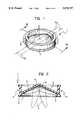
- FIG. 1is a perspective view of a heart valve prosthesis produced according to the invention
- FIG. 2is a section taken on the line II--II of FIG. 1, on an enlarged scale,
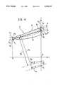
- FIG. 3is a perspective view of one of the parts shown in FIGS. 1 and 2 on an even larger scale, showing specifically the geometric parameters of the part in question, and
- FIG. 4is a section taken in the plane indicated by the arrows IV--IV of FIG. 3.
- a heart valve prosthesisis intended to be used to replace a natural heart valve (for example, the aortic valve or the mitral valve) which is suffering from damage or heart disease.
- a natural heart valvefor example, the aortic valve or the mitral valve
- a generally-annular stent 2defining a passage for the blood
- obturatorsusually two, indicated 3, having a general eyelid or fingernail shape.
- the obturators (leaflets) 3are mounted in the stent so that they can pivot between a closed position (shown in continuous outline in FIG. 2) and an open position (shown in broken outline, also in FIG. 2).
- this pivoting movementcan be defined as a movement which takes place about respective diametral lines (more precisely, subdiametral lines) which can be identified--at least approximately--by axes X 3 (see FIG. 1).
- obturators 3may be able to move gradually during the pivoting of the obturators 3, which thus takes place about an axis that moves continuously along a straight, arcuate or falcate path as the obturator pivots.
- the obturators 3In the open position, the obturators 3 extend in positions almost perpendicular to the general plane of the stent 2 and thus enable the blood to flow freely through the prosthesis in a first direction (downwards with reference to the orientation of FIG. 2).
- the blood pressureautomatically brings the obturators 3 into the closed position in which the obturators 3 together occlude the orifice of the prosthesis, preventing the blood from flowing in the opposite direction (upwards with reference to the orientation of FIG. 2).
- the stent 2is made from a rigid biocompatible material, for example, metal or a carbonaceous material, or even a combination of the two (a metal core covered by carbonaceous material, or carbonaceous material with a metal reinforcing structure).
- the stent 2usually has a groove 4 in its outer surface for facilitating the mounting of a suture ring around the stent 2. This enables the prosthesis to be fixed to the annulus of the natural valve after the removal of its valve flaps.
- the profile of the suture ring Rwhich is made from a textile of biocompatible yarn (for example, yarn made from the materials known under the trade names of Dacron or Teflon), is shown schematically in broken outline in FIG. 1 only.
- the obturators 3may be constituted by a core (for example, of graphite) covered with a layer of biocompatible carbonaceous material deposited by high-temperature pyrolysis (pyrocarbon) or by means of a vapour-phase deposition method.
- the obturators 3may be made entirely of carbonaceous material and other biocompatible materials. Similar layers of biocompatible carbonaceous material may also be applied to the stent 2 and to the suture ring R, at least on the parts intended to be exposed to the blood flow.
- the obturators 3are generally eyelid- or fingernail-shaped and each can be seen to have:
- a first end edge 6 of the prosthesiswhich is generally flat (but may be rounded at its lower corner) and extends between the vertices 5 in an arcuate arrangement, thus constituting the "inner" edge of the obturator 3, that is, the edge near the pivot axis X 3 ,
- a second end edgewhich extends between the vertices 5 along a generally arcuate path so as to define the outer edge of the obturator 3 (that is, the edge remote from the pivot axis X 3 ) and is intended to cooperate with the profile of the stent 2 in the closed position, as shown in FIG. 2, and
- the bloodis intended to flow over the upper surface 9 during the opening movement, whilst the lower surface 10 is that against which the blood pressure acts during the closure of the valve.
- both the surfaces 9 and 10are constituted by substantially cylindrical surfaces each having a respective radius of curvature and a respective principal axis.
- substantially cylindricalapplied to the surfaces 9 and 10 in the present description and in the claims which follow is intended to apply not only to strictly cylindrical surfaces, but also generally to surfaces which, although not being exactly cylindrical overall, have an arcuate shape (for example, an elliptical profile) which is sufficiently regular to enable the definition of an average radius of curvature and of a locus of the centres of curvature gathered around an axis.
- the geometry of the upper surface 9 of the obturator 3is determined on the basis of the flow conditions and conditions of a functional character, such as: the desired angle of pivoting between the open and closed positions of the obturator, the maximum depth of the cross-section of the valve, the conditions of the blood flow through the valve orifice (its centrality and distribution in the aperture), etc.
- the obturator 3is delimited in the plane yz by the surface of its front or inner edge 6 having the equation:
- the central point C 9 and the ends P 9 of the upper surface 9 which are situated in correspondence with the inner or front edge 6, as well as the central point Q 9 of the same surface situated in correspondence with its rear edge 7,are defined by the coordinates:
- the radius of curvature R 2 of the upper surface 9is greater than the radius of curvature R 2 i of the lower surface 10,
- the principal axes X 9 and X 10generally converge from the outer or rear edge 7 towards the inner or front edge 6, or at most are parallel, and
- the principal axis X 10 of the cylindrical surface constituting the lower surface 10is nearer the obturator 3 than the principal axis X 9 of the upper surface 9.
- this means that the front or inner edge 6 is thinnest in correspondence with the central region of the obturator (the points C 9 , C 10 ) and becomes regularly and progressively thicker towards the ends of the edge (the points P 9 , P 10 ), whilst retaining the general symmetry of the obturator about the plane y0, and the thickness of the obturator 3 decreases gradually or is constant from the front or inner edge 6 (C 9 , C 10 ) to the rear or outer edge 7 (Q 9 , Q 10 ).
- the quantities S o and S qconstitute design parameters which are preferred to the distances (z c -z c i ) and (z q -z q i ) in the design definition of the characteristics of the valve, since they are more readily derived from thickness of the actuator in the general direction of its development.
- this minimisationusually involves the selection of the smallest value of S q compatible with the structural requirements taken into consideration in the previous step,
- the equations (12) to (17)can easily be inverted in order to determine the geometric parameters R 2 i , z o i and theta i of the cylindrical (or substantially cylindrical) surface defining the lower surface 10 of the obturator which satisfies the conditions set.
Landscapes
- Health & Medical Sciences (AREA)
- Cardiology (AREA)
- Oral & Maxillofacial Surgery (AREA)
- Transplantation (AREA)
- Engineering & Computer Science (AREA)
- Biomedical Technology (AREA)
- Heart & Thoracic Surgery (AREA)
- Vascular Medicine (AREA)
- Life Sciences & Earth Sciences (AREA)
- Animal Behavior & Ethology (AREA)
- General Health & Medical Sciences (AREA)
- Public Health (AREA)
- Veterinary Medicine (AREA)
- Prostheses (AREA)
Abstract
Description
x=0 (1)
x.sup.2 +y.sup.2 =R.sub.1.sup.2 (2)
C.sub.9 →x=0; y=0; Z=Zc (5)
P.sub.9 →x=0; y=±R.sub.1 ; Z=Zp (6)
Q.sub.9 →x=-R.sub.1 ; y=0; Z=Zq (7)
S.sub.o =1.0 mm, S.sub.q =1.2 mm, (z.sub.p -z.sub.p.sup.i)=1.6 mm.
Claims (6)
Applications Claiming Priority (2)
| Application Number | Priority Date | Filing Date | Title |
|---|---|---|---|
| IT67909/88AIT1224479B (en) | 1988-10-11 | 1988-10-11 | CARDIAC VALVE PROSTHESIS SHUTTER CARDIAC VALVE PROSTHESIS PROVIDED WITH SUCH A SHUTTER AND RELATED MANUFACTURING PROCEDURE |
| IT67909A/88 | 1988-10-11 |
Publications (1)
| Publication Number | Publication Date |
|---|---|
| US5078737Atrue US5078737A (en) | 1992-01-07 |
Family
ID=11306292
Family Applications (1)
| Application Number | Title | Priority Date | Filing Date |
|---|---|---|---|
| US07/419,071Expired - LifetimeUS5078737A (en) | 1988-10-11 | 1989-10-10 | Obturator for heart valve prostheses, a heart valve prosthesis provided with such an obturator, and a method for the manufacture thereof |
Country Status (6)
| Country | Link |
|---|---|
| US (1) | US5078737A (en) |
| EP (1) | EP0378974B1 (en) |
| AT (1) | ATE87812T1 (en) |
| DE (1) | DE68905916T2 (en) |
| ES (1) | ES2039939T3 (en) |
| IT (1) | IT1224479B (en) |
Cited By (26)
| Publication number | Priority date | Publication date | Assignee | Title |
|---|---|---|---|---|
| US5824062A (en)* | 1995-03-29 | 1998-10-20 | Cv Dynamics, Inc. | Bileaflet heart valve having dynamic pivot mechanism |
| US6296663B1 (en) | 1995-03-29 | 2001-10-02 | Medical Cv, Inc. | Bileaflet heart valve having open channel and swivel pivots |
| US20050203617A1 (en)* | 2004-02-27 | 2005-09-15 | Cardiacmd, Inc. | Prosthetic heart valves, scaffolding structures, and systems and methods for implantation of same |
| US20070073387A1 (en)* | 2004-02-27 | 2007-03-29 | Forster David C | Prosthetic Heart Valves, Support Structures And Systems And Methods For Implanting The Same |
| US20070203575A1 (en)* | 2006-02-27 | 2007-08-30 | Cardiacmd, Inc., A California Corporation | Methods and devices for delivery of prosthetic heart valves and other prosthetics |
| US20070203560A1 (en)* | 2006-02-27 | 2007-08-30 | Cardiacmd, Inc., A California Corporation | Methods and devices for delivery of prosthetic heart valves and other prosthetics |
| US20080009746A1 (en)* | 2006-05-24 | 2008-01-10 | Aortx, Inc., A California Corporation | Assessment of aortic heart valve to facilitate repair or replacement |
| US20090099554A1 (en)* | 2006-06-20 | 2009-04-16 | Forster David C | Elongate Flexible Torque Instruments And Methods Of Use |
| US20090132035A1 (en)* | 2004-02-27 | 2009-05-21 | Roth Alex T | Prosthetic Heart Valves, Support Structures and Systems and Methods for Implanting the Same |
| US20090209955A1 (en)* | 2006-06-20 | 2009-08-20 | Forster David C | Prosthetic valve implant site preparation techniques |
| US20090210052A1 (en)* | 2006-06-20 | 2009-08-20 | Forster David C | Prosthetic heart valves, support structures and systems and methods for implanting same |
| US20090228098A1 (en)* | 2006-06-21 | 2009-09-10 | Forster David C | Prosthetic valve implantation systems |
| US20100256752A1 (en)* | 2006-09-06 | 2010-10-07 | Forster David C | Prosthetic heart valves, support structures and systems and methods for implanting the same, |
| US8845717B2 (en) | 2011-01-28 | 2014-09-30 | Middle Park Medical, Inc. | Coaptation enhancement implant, system, and method |
| US8888843B2 (en) | 2011-01-28 | 2014-11-18 | Middle Peak Medical, Inc. | Device, system, and method for transcatheter treatment of valve regurgitation |
| US9592121B1 (en) | 2015-11-06 | 2017-03-14 | Middle Peak Medical, Inc. | Device, system, and method for transcatheter treatment of valvular regurgitation |
| US10123874B2 (en) | 2017-03-13 | 2018-11-13 | Middle Peak Medical, Inc. | Device, system, and method for transcatheter treatment of valvular regurgitation |
| US10166098B2 (en) | 2013-10-25 | 2019-01-01 | Middle Peak Medical, Inc. | Systems and methods for transcatheter treatment of valve regurgitation |
| US10251635B2 (en) | 2014-06-24 | 2019-04-09 | Middle Peak Medical, Inc. | Systems and methods for anchoring an implant |
| US10413101B2 (en) | 2016-12-19 | 2019-09-17 | Christopher Aldo Porco | Attachable plate and cup assembly |
| US10478303B2 (en) | 2017-03-13 | 2019-11-19 | Polares Medical Inc. | Device, system, and method for transcatheter treatment of valvular regurgitation |
| US10500048B2 (en) | 2014-06-18 | 2019-12-10 | Polares Medical Inc. | Mitral valve implants for the treatment of valvular regurgitation |
| US10648581B2 (en)* | 2017-12-15 | 2020-05-12 | Hamilton Sundstrand Corporation | Check valves |
| US10653524B2 (en) | 2017-03-13 | 2020-05-19 | Polares Medical Inc. | Device, system, and method for transcatheter treatment of valvular regurgitation |
| US11464634B2 (en) | 2020-12-16 | 2022-10-11 | Polares Medical Inc. | Device, system, and method for transcatheter treatment of valvular regurgitation with secondary anchors |
| US11759321B2 (en) | 2021-06-25 | 2023-09-19 | Polares Medical Inc. | Device, system, and method for transcatheter treatment of valvular regurgitation |
Citations (9)
| Publication number | Priority date | Publication date | Assignee | Title |
|---|---|---|---|---|
| US3926215A (en)* | 1973-08-03 | 1975-12-16 | Nat Res Dev | Fluid control valves |
| DE3028981A1 (en)* | 1979-07-30 | 1981-02-26 | Carbomedics Inc | HEART VALVE PROSTHESIS |
| US4254508A (en)* | 1979-07-30 | 1981-03-10 | Carbomedics, Inc. | Bileaflet heart valve with improved pivot |
| US4308624A (en)* | 1979-08-07 | 1982-01-05 | Hemex, Inc. | Heart valve prosthesis |
| US4451937A (en)* | 1982-02-08 | 1984-06-05 | Hemex, Inc. | Heart valve having ear guided occluders |
| EP0176337A1 (en)* | 1984-09-24 | 1986-04-02 | Carbomedics Inc. | Heart valve prosthesis |
| EP0211576A2 (en)* | 1985-07-24 | 1987-02-25 | McQueen, David M. | A heart valve prosthesis |
| WO1989000033A1 (en)* | 1987-07-02 | 1989-01-12 | Pacific Biomedical Holdings, Ltd. | Heart valve with disc occluder |
| US4888010A (en)* | 1988-12-14 | 1989-12-19 | Carbomedics, Inc. | Heart valve prosthesis with improved recess design |
- 1988
- 1988-10-11ITIT67909/88Apatent/IT1224479B/enactive
- 1989
- 1989-10-10EPEP89830433Apatent/EP0378974B1/ennot_activeExpired - Lifetime
- 1989-10-10USUS07/419,071patent/US5078737A/ennot_activeExpired - Lifetime
- 1989-10-10DEDE8989830433Tpatent/DE68905916T2/ennot_activeExpired - Lifetime
- 1989-10-10ESES198989830433Tpatent/ES2039939T3/ennot_activeExpired - Lifetime
- 1989-10-10ATAT89830433Tpatent/ATE87812T1/ennot_activeIP Right Cessation
Patent Citations (9)
| Publication number | Priority date | Publication date | Assignee | Title |
|---|---|---|---|---|
| US3926215A (en)* | 1973-08-03 | 1975-12-16 | Nat Res Dev | Fluid control valves |
| DE3028981A1 (en)* | 1979-07-30 | 1981-02-26 | Carbomedics Inc | HEART VALVE PROSTHESIS |
| US4254508A (en)* | 1979-07-30 | 1981-03-10 | Carbomedics, Inc. | Bileaflet heart valve with improved pivot |
| US4308624A (en)* | 1979-08-07 | 1982-01-05 | Hemex, Inc. | Heart valve prosthesis |
| US4451937A (en)* | 1982-02-08 | 1984-06-05 | Hemex, Inc. | Heart valve having ear guided occluders |
| EP0176337A1 (en)* | 1984-09-24 | 1986-04-02 | Carbomedics Inc. | Heart valve prosthesis |
| EP0211576A2 (en)* | 1985-07-24 | 1987-02-25 | McQueen, David M. | A heart valve prosthesis |
| WO1989000033A1 (en)* | 1987-07-02 | 1989-01-12 | Pacific Biomedical Holdings, Ltd. | Heart valve with disc occluder |
| US4888010A (en)* | 1988-12-14 | 1989-12-19 | Carbomedics, Inc. | Heart valve prosthesis with improved recess design |
Cited By (72)
| Publication number | Priority date | Publication date | Assignee | Title |
|---|---|---|---|---|
| US5824062A (en)* | 1995-03-29 | 1998-10-20 | Cv Dynamics, Inc. | Bileaflet heart valve having dynamic pivot mechanism |
| US6296663B1 (en) | 1995-03-29 | 2001-10-02 | Medical Cv, Inc. | Bileaflet heart valve having open channel and swivel pivots |
| US8728156B2 (en) | 2004-02-27 | 2014-05-20 | Cardiac MD, Inc. | Prosthetic heart valves, scaffolding structures, and systems and methods for implantation of same |
| US20050203615A1 (en)* | 2004-02-27 | 2005-09-15 | Cardiacmd, Inc. | Prosthetic heart valves, scaffolding structures, and systems and methods for implantation of same |
| US20070073387A1 (en)* | 2004-02-27 | 2007-03-29 | Forster David C | Prosthetic Heart Valves, Support Structures And Systems And Methods For Implanting The Same |
| US20050203617A1 (en)* | 2004-02-27 | 2005-09-15 | Cardiacmd, Inc. | Prosthetic heart valves, scaffolding structures, and systems and methods for implantation of same |
| US7785341B2 (en) | 2004-02-27 | 2010-08-31 | Aortx, Inc. | Prosthetic heart valves, scaffolding structures, and systems and methods for implantation of same |
| US8608770B2 (en) | 2004-02-27 | 2013-12-17 | Cardiacmd, Inc. | Prosthetic heart valves, scaffolding structures, and systems and methods for implantation of same |
| US8430925B2 (en) | 2004-02-27 | 2013-04-30 | Cardiacmd, Inc. | Prosthetic heart valves, scaffolding structures, and systems and methods for implantation of same |
| US9168134B2 (en) | 2004-02-27 | 2015-10-27 | Cardiacmd, Inc. | Method for delivering a prosthetic heart valve with an expansion member |
| US20090132035A1 (en)* | 2004-02-27 | 2009-05-21 | Roth Alex T | Prosthetic Heart Valves, Support Structures and Systems and Methods for Implanting the Same |
| US8128692B2 (en) | 2004-02-27 | 2012-03-06 | Aortx, Inc. | Prosthetic heart valves, scaffolding structures, and systems and methods for implantation of same |
| US20110082540A1 (en)* | 2004-02-27 | 2011-04-07 | Forster David C | Prosthetic Heart Valves, Scaffolding Structures, and Systems and Methods for Implantation of Same |
| US20100305691A1 (en)* | 2004-02-27 | 2010-12-02 | Forster David C | Prosthetic Heart Valves, Scaffolding Structures, and Systems and Methods for Implantation of Same |
| US20100256724A1 (en)* | 2004-02-27 | 2010-10-07 | Forster David C | Prosthetic Heart Valves, Scaffolding Structures, and Systems and Methods for Implantation of Same |
| US8147541B2 (en) | 2006-02-27 | 2012-04-03 | Aortx, Inc. | Methods and devices for delivery of prosthetic heart valves and other prosthetics |
| US8403981B2 (en) | 2006-02-27 | 2013-03-26 | CardiacMC, Inc. | Methods and devices for delivery of prosthetic heart valves and other prosthetics |
| US20070203575A1 (en)* | 2006-02-27 | 2007-08-30 | Cardiacmd, Inc., A California Corporation | Methods and devices for delivery of prosthetic heart valves and other prosthetics |
| US7749266B2 (en) | 2006-02-27 | 2010-07-06 | Aortx, Inc. | Methods and devices for delivery of prosthetic heart valves and other prosthetics |
| US20070203560A1 (en)* | 2006-02-27 | 2007-08-30 | Cardiacmd, Inc., A California Corporation | Methods and devices for delivery of prosthetic heart valves and other prosthetics |
| US20070203561A1 (en)* | 2006-02-27 | 2007-08-30 | Cardiacmd, Inc. A California Corporation | Methods and devices for delivery of prosthetic heart valves and other prosthetics |
| US8057396B2 (en) | 2006-05-24 | 2011-11-15 | Phoenix Biomedical, Inc. | Device for assessing a cardiac valve |
| US8585594B2 (en) | 2006-05-24 | 2013-11-19 | Phoenix Biomedical, Inc. | Methods of assessing inner surfaces of body lumens or organs |
| US20080009746A1 (en)* | 2006-05-24 | 2008-01-10 | Aortx, Inc., A California Corporation | Assessment of aortic heart valve to facilitate repair or replacement |
| US20100217119A1 (en)* | 2006-05-24 | 2010-08-26 | Forster David C | Assessment Of Aortic Heart Valve To Facilitate Repair Or Replacement |
| US20090099554A1 (en)* | 2006-06-20 | 2009-04-16 | Forster David C | Elongate Flexible Torque Instruments And Methods Of Use |
| US8376865B2 (en) | 2006-06-20 | 2013-02-19 | Cardiacmd, Inc. | Torque shaft and torque shaft drive |
| US8500799B2 (en) | 2006-06-20 | 2013-08-06 | Cardiacmd, Inc. | Prosthetic heart valves, support structures and systems and methods for implanting same |
| US20090209955A1 (en)* | 2006-06-20 | 2009-08-20 | Forster David C | Prosthetic valve implant site preparation techniques |
| US20090210052A1 (en)* | 2006-06-20 | 2009-08-20 | Forster David C | Prosthetic heart valves, support structures and systems and methods for implanting same |
| US8142492B2 (en) | 2006-06-21 | 2012-03-27 | Aortx, Inc. | Prosthetic valve implantation systems |
| US20090228098A1 (en)* | 2006-06-21 | 2009-09-10 | Forster David C | Prosthetic valve implantation systems |
| US20100256752A1 (en)* | 2006-09-06 | 2010-10-07 | Forster David C | Prosthetic heart valves, support structures and systems and methods for implanting the same, |
| US9610163B2 (en) | 2011-01-28 | 2017-04-04 | Middle Peak Medical, Inc. | Coaptation enhancement implant, system, and method |
| US11648120B2 (en) | 2011-01-28 | 2023-05-16 | Polares Medical Inc. | Coaptation enhancement implant, system, and method |
| US9592118B2 (en) | 2011-01-28 | 2017-03-14 | Middle Peak Medical, Inc. | Device, system, and method for transcatheter treatment of valve regurgitation |
| US12150856B2 (en) | 2011-01-28 | 2024-11-26 | Polares Medical Inc. | Device, system, and method for transcatheter treatment of valve regurgitation |
| US8845717B2 (en) | 2011-01-28 | 2014-09-30 | Middle Park Medical, Inc. | Coaptation enhancement implant, system, and method |
| US12109116B2 (en) | 2011-01-28 | 2024-10-08 | Polares Medical Inc. | Coaptation enhancement implant, system, and method |
| US11678986B2 (en) | 2011-01-28 | 2023-06-20 | Polares Medical Inc. | Device, system, and method for transcatheter treatment of valve regurgitation |
| US8888843B2 (en) | 2011-01-28 | 2014-11-18 | Middle Peak Medical, Inc. | Device, system, and method for transcatheter treatment of valve regurgitation |
| US11648119B2 (en) | 2011-01-28 | 2023-05-16 | Polares Medical Inc. | Coaptation enhancement implant, system, and method |
| US11426279B2 (en) | 2011-01-28 | 2022-08-30 | Polares Medical Inc. | Coaptation enhancement implant, system, and method |
| US10470883B2 (en) | 2011-01-28 | 2019-11-12 | Polares Medical Inc. | Coaptation enhancement implant, system, and method |
| US11419722B2 (en) | 2011-01-28 | 2022-08-23 | Polares Medical Inc. | Device, system, and method for transcatheter treatment of valve regurgitation |
| US11413145B2 (en) | 2011-01-28 | 2022-08-16 | Polares Medical Inc. | Coaptation enhancement implant, system, and method |
| US10512542B2 (en) | 2011-01-28 | 2019-12-24 | Polares Medical Inc. | Device, system, and method for transcatheter treatment of valve regurgitation |
| US11497606B2 (en) | 2013-10-25 | 2022-11-15 | Polares Medical Inc. | Systems and methods for transcatheter treatment of valve regurgitation |
| US12350153B2 (en) | 2013-10-25 | 2025-07-08 | Polares Medical Inc. | Systems and methods for transcatheter treatment of valve regurgitation |
| US10166098B2 (en) | 2013-10-25 | 2019-01-01 | Middle Peak Medical, Inc. | Systems and methods for transcatheter treatment of valve regurgitation |
| US11000372B2 (en) | 2013-10-25 | 2021-05-11 | Polares Medical Inc. | Systems and methods for transcatheter treatment of valve regurgitation |
| US11974921B2 (en) | 2014-06-18 | 2024-05-07 | Polares Medical Inc. | Mitral valve implants for the treatment of valvular regurgitation |
| US10500048B2 (en) | 2014-06-18 | 2019-12-10 | Polares Medical Inc. | Mitral valve implants for the treatment of valvular regurgitation |
| US11622759B2 (en) | 2014-06-24 | 2023-04-11 | Polares Medical Inc. | Systems and methods for anchoring an implant |
| US10251635B2 (en) | 2014-06-24 | 2019-04-09 | Middle Peak Medical, Inc. | Systems and methods for anchoring an implant |
| US9592121B1 (en) | 2015-11-06 | 2017-03-14 | Middle Peak Medical, Inc. | Device, system, and method for transcatheter treatment of valvular regurgitation |
| US11160656B2 (en) | 2015-11-06 | 2021-11-02 | Polares Medical Inc. | Device, system, and method for transcatheter treatment of valvular regurgitation |
| US10376365B2 (en) | 2015-11-06 | 2019-08-13 | Middle Peak Medical, Inc. | Device, system, and method for transcatheter treatment of valvular regurgitation |
| US10413101B2 (en) | 2016-12-19 | 2019-09-17 | Christopher Aldo Porco | Attachable plate and cup assembly |
| US12285336B2 (en) | 2017-03-13 | 2025-04-29 | Polares Medical Inc. | Device, system, and method for transcatheter treatment of valvular regurgitation |
| US11534302B2 (en) | 2017-03-13 | 2022-12-27 | Polares Medical Inc. | Device, system, and method for transcatheter treatment of valvular regurgitation |
| US10478303B2 (en) | 2017-03-13 | 2019-11-19 | Polares Medical Inc. | Device, system, and method for transcatheter treatment of valvular regurgitation |
| US11672659B2 (en) | 2017-03-13 | 2023-06-13 | Polares Medical Inc. | Device, system, and method for transcatheter treatment of valvular regurgitation |
| US10702386B2 (en) | 2017-03-13 | 2020-07-07 | Polares Medical Inc. | Device, system, and method for transcatheter treatment of valvular regurgitation |
| US10123874B2 (en) | 2017-03-13 | 2018-11-13 | Middle Peak Medical, Inc. | Device, system, and method for transcatheter treatment of valvular regurgitation |
| US11298229B2 (en) | 2017-03-13 | 2022-04-12 | Polares Medical Inc. | Device, system, and method for transcatheter treatment of valvular regurgitation |
| US12295845B2 (en) | 2017-03-13 | 2025-05-13 | Polares Medical Inc. | Device, system, and method for transcatheter treatment of valvular regurgitation |
| US10653524B2 (en) | 2017-03-13 | 2020-05-19 | Polares Medical Inc. | Device, system, and method for transcatheter treatment of valvular regurgitation |
| US12419747B2 (en) | 2017-03-13 | 2025-09-23 | Polares Medical Inc. | Device, system, and method for transcatheter treatment of valvular regurgitation |
| US10648581B2 (en)* | 2017-12-15 | 2020-05-12 | Hamilton Sundstrand Corporation | Check valves |
| US11464634B2 (en) | 2020-12-16 | 2022-10-11 | Polares Medical Inc. | Device, system, and method for transcatheter treatment of valvular regurgitation with secondary anchors |
| US11759321B2 (en) | 2021-06-25 | 2023-09-19 | Polares Medical Inc. | Device, system, and method for transcatheter treatment of valvular regurgitation |
Also Published As
| Publication number | Publication date |
|---|---|
| DE68905916D1 (en) | 1993-05-13 |
| IT8867909A0 (en) | 1988-10-11 |
| IT1224479B (en) | 1990-10-04 |
| EP0378974A1 (en) | 1990-07-25 |
| DE68905916T2 (en) | 1993-09-02 |
| EP0378974B1 (en) | 1993-04-07 |
| ATE87812T1 (en) | 1993-04-15 |
| ES2039939T3 (en) | 1993-10-01 |
Similar Documents
| Publication | Publication Date | Title |
|---|---|---|
| US5078737A (en) | Obturator for heart valve prostheses, a heart valve prosthesis provided with such an obturator, and a method for the manufacture thereof | |
| US5002567A (en) | Prosthetic heart valve | |
| US6206918B1 (en) | Heart valve prosthesis having a pivot design for improving flow characteristics | |
| US4178639A (en) | Two-leaflet heart valve | |
| EP0023797B1 (en) | Heart valve prosthesis | |
| US6454798B1 (en) | Polymer heart valve with helical coaption surface | |
| US6051022A (en) | Bileaflet valve having non-parallel pivot axes | |
| US5522886A (en) | Heart valve prostheses | |
| US5314467A (en) | Composite curvature bileaflet prosthetic heart valve with serpentine curve hinge recesses | |
| US5326372A (en) | Prosthetic heart valve assembly | |
| EP2147659B1 (en) | Heart valve prosthesis | |
| US6096075A (en) | Prosthetic heart valve | |
| US4692165A (en) | Heart valve | |
| CA1163753A (en) | Heart valve with pivoted occluder | |
| US5908451A (en) | Prosthetic heart valve | |
| US4822353A (en) | Heart valve | |
| JP2000513248A (en) | Prosthetic mitral and heart valves | |
| JPH072168B2 (en) | Artificial heart valve | |
| US5116366A (en) | Prosthetic heart valve | |
| EP0289404B1 (en) | Heart valve | |
| US5123920A (en) | Prosthetic heart valve | |
| US5078738A (en) | Artificial cardiac valve | |
| US5861030A (en) | Bileaflet mechanical heart valve having arrowhead slot hinge configuration | |
| EP0300512A2 (en) | Heart valve prothesis | |
| WO2001006958A1 (en) | Hybrid prosthetic heart valve |
Legal Events
| Date | Code | Title | Description |
|---|---|---|---|
| AS | Assignment | Owner name:SORIN BIOMEDICA S.P.A. STRADA PER CRESCENTINO, 130 Free format text:ASSIGNMENT OF ASSIGNORS INTEREST.;ASSIGNORS:BONA, GIOACHINO;RINALDI, STEFANO;VALLANA, FRANCO;REEL/FRAME:005157/0971 Effective date:19891004 | |
| FEPP | Fee payment procedure | Free format text:PAYOR NUMBER ASSIGNED (ORIGINAL EVENT CODE: ASPN); ENTITY STATUS OF PATENT OWNER: LARGE ENTITY | |
| STCF | Information on status: patent grant | Free format text:PATENTED CASE | |
| FPAY | Fee payment | Year of fee payment:4 | |
| AS | Assignment | Owner name:SORIN BIOMEDICA CARDIO S.P.A., ITALY Free format text:CERTIFIED COPY OF DEED OF AMENDMENT TO DEED OF CONFERMENT OF INDUSTRIAL COMPANY UNIT FROM SORIN BIOMEDICA S.P.A. TO SORIN BIOMEDICA CARDIO S.P.A. INCLUDING THE ASSIGNMENT OF PATENTS, TOGETHER WITH A NOTARIZED TRANSLATION OF THE DEED AND A LIST OF THE UNITED STATES PATENTS AND APPLICATIONS BEING TRANSFERRED;ASSIGNOR:SORIN BIOMEDICA S.P.A.;REEL/FRAME:008098/0001 Effective date:19931229 | |
| FEPP | Fee payment procedure | Free format text:PAYER NUMBER DE-ASSIGNED (ORIGINAL EVENT CODE: RMPN); ENTITY STATUS OF PATENT OWNER: LARGE ENTITY Free format text:PAYOR NUMBER ASSIGNED (ORIGINAL EVENT CODE: ASPN); ENTITY STATUS OF PATENT OWNER: LARGE ENTITY | |
| FPAY | Fee payment | Year of fee payment:8 | |
| FPAY | Fee payment | Year of fee payment:12 |