US5078469A - Optical system which allows coincident viewing, illuminating and photographing - Google Patents
Optical system which allows coincident viewing, illuminating and photographingDownload PDFInfo
- Publication number
- US5078469A US5078469AUS07/419,761US41976189AUS5078469AUS 5078469 AUS5078469 AUS 5078469AUS 41976189 AUS41976189 AUS 41976189AUS 5078469 AUS5078469 AUS 5078469A
- Authority
- US
- United States
- Prior art keywords
- illumination
- loupe
- viewing
- view
- beam splitter
- Prior art date
- Legal status (The legal status is an assumption and is not a legal conclusion. Google has not performed a legal analysis and makes no representation as to the accuracy of the status listed.)
- Expired - Fee Related
Links
- 230000003287optical effectEffects0.000titleclaimsdescription14
- 238000005286illuminationMethods0.000claimsabstractdescription46
- 241000282461Canis lupusSpecies0.000claimsdescription17
- 230000000694effectsEffects0.000abstractdescription6
- 239000002699waste materialSubstances0.000abstractdescription4
- 238000000034methodMethods0.000description5
- 239000013307optical fiberSubstances0.000description5
- 230000005540biological transmissionEffects0.000description4
- 230000005855radiationEffects0.000description4
- 230000010287polarizationEffects0.000description3
- 239000000835fiberSubstances0.000description2
- 239000006096absorbing agentSubstances0.000description1
- 230000002238attenuated effectEffects0.000description1
- 230000008878couplingEffects0.000description1
- 238000010168coupling processMethods0.000description1
- 238000005859coupling reactionMethods0.000description1
- 210000001061foreheadAnatomy0.000description1
- 239000011521glassSubstances0.000description1
- 210000003128headAnatomy0.000description1
- 230000002452interceptive effectEffects0.000description1
- 239000003562lightweight materialSubstances0.000description1
- 238000012544monitoring processMethods0.000description1
- 230000002093peripheral effectEffects0.000description1
- 230000035945sensitivityEffects0.000description1
- 230000001360synchronised effectEffects0.000description1
Images


Classifications
- G—PHYSICS
- G02—OPTICS
- G02B—OPTICAL ELEMENTS, SYSTEMS OR APPARATUS
- G02B7/00—Mountings, adjusting means, or light-tight connections, for optical elements
- G02B7/002—Mounting on the human body
- A—HUMAN NECESSITIES
- A61—MEDICAL OR VETERINARY SCIENCE; HYGIENE
- A61B—DIAGNOSIS; SURGERY; IDENTIFICATION
- A61B3/00—Apparatus for testing the eyes; Instruments for examining the eyes
- A61B3/10—Objective types, i.e. instruments for examining the eyes independent of the patients' perceptions or reactions
- A61B3/13—Ophthalmic microscopes
- A61B3/132—Ophthalmic microscopes in binocular arrangement
- A—HUMAN NECESSITIES
- A61—MEDICAL OR VETERINARY SCIENCE; HYGIENE
- A61B—DIAGNOSIS; SURGERY; IDENTIFICATION
- A61B90/00—Instruments, implements or accessories specially adapted for surgery or diagnosis and not covered by any of the groups A61B1/00 - A61B50/00, e.g. for luxation treatment or for protecting wound edges
- A61B90/36—Image-producing devices or illumination devices not otherwise provided for
- A61B90/361—Image-producing devices, e.g. surgical cameras
- G—PHYSICS
- G02—OPTICS
- G02B—OPTICAL ELEMENTS, SYSTEMS OR APPARATUS
- G02B21/00—Microscopes
- G02B21/18—Arrangements with more than one light path, e.g. for comparing two specimens
- G—PHYSICS
- G02—OPTICS
- G02B—OPTICAL ELEMENTS, SYSTEMS OR APPARATUS
- G02B25/00—Eyepieces; Magnifying glasses
- G02B25/002—Magnifying glasses
- G02B25/004—Magnifying glasses having binocular arrangement
- G—PHYSICS
- G02—OPTICS
- G02B—OPTICAL ELEMENTS, SYSTEMS OR APPARATUS
- G02B25/00—Eyepieces; Magnifying glasses
- G02B25/02—Eyepieces; Magnifying glasses with means for illuminating object viewed
- G—PHYSICS
- G02—OPTICS
- G02C—SPECTACLES; SUNGLASSES OR GOGGLES INSOFAR AS THEY HAVE THE SAME FEATURES AS SPECTACLES; CONTACT LENSES
- G02C7/00—Optical parts
- G02C7/02—Lenses; Lens systems ; Methods of designing lenses
- G02C7/08—Auxiliary lenses; Arrangements for varying focal length
- G02C7/088—Lens systems mounted to spectacles
- G—PHYSICS
- G03—PHOTOGRAPHY; CINEMATOGRAPHY; ANALOGOUS TECHNIQUES USING WAVES OTHER THAN OPTICAL WAVES; ELECTROGRAPHY; HOLOGRAPHY
- G03B—APPARATUS OR ARRANGEMENTS FOR TAKING PHOTOGRAPHS OR FOR PROJECTING OR VIEWING THEM; APPARATUS OR ARRANGEMENTS EMPLOYING ANALOGOUS TECHNIQUES USING WAVES OTHER THAN OPTICAL WAVES; ACCESSORIES THEREFOR
- G03B15/00—Special procedures for taking photographs; Apparatus therefor
- G03B15/14—Special procedures for taking photographs; Apparatus therefor for taking photographs during medical operations
- A—HUMAN NECESSITIES
- A61—MEDICAL OR VETERINARY SCIENCE; HYGIENE
- A61B—DIAGNOSIS; SURGERY; IDENTIFICATION
- A61B90/00—Instruments, implements or accessories specially adapted for surgery or diagnosis and not covered by any of the groups A61B1/00 - A61B50/00, e.g. for luxation treatment or for protecting wound edges
- A61B90/36—Image-producing devices or illumination devices not otherwise provided for
- A61B90/361—Image-producing devices, e.g. surgical cameras
- A61B2090/3616—Magnifying glass
- A—HUMAN NECESSITIES
- A61—MEDICAL OR VETERINARY SCIENCE; HYGIENE
- A61B—DIAGNOSIS; SURGERY; IDENTIFICATION
- A61B90/00—Instruments, implements or accessories specially adapted for surgery or diagnosis and not covered by any of the groups A61B1/00 - A61B50/00, e.g. for luxation treatment or for protecting wound edges
- A61B90/50—Supports for surgical instruments, e.g. articulated arms
- A61B2090/502—Headgear, e.g. helmet, spectacles
Definitions
- the present inventionrelates to optical loupes utilized in surgical and other procedures for providing magnified viewing and illumination of fields of interest to a surgeon or other user.
- Such systemstypically include first and second loupes which permit binocular viewing with magnification of a region of interest. Illumination has been provided in the past by a separate illumination source, typically located and supported in the forehead region of the surgeon.
- the illumination functionis combined into the viewing loupe in order to avoid the shadow cast in the field of view by a light source located away from the viewing axis.
- a light sourcelocated away from the viewing axis.
- loupe beam splitter opticsbecause of the attenuation in loupe beam splitter optics, some illumination is lost both in the path of illumination from the source and in the path of viewing by the operator of the field of view. It is important that the optics minimize attenuation and maximize the perceived illumination of the field of view while avoiding flare effects.
- a binocular loupe systemfor surgical or related usages.
- the loupe systemprovides illumination of the field of view along the viewing axis and includes optics which enhance the illumination and brilliance of the field of view while minimizing the effects of flare resulting from the presence of intense illuminating radiation passing through the optics which also lie in the view path of the loupe.
- Additional embodimentsprovide video viewing of the field of view and remote presentation of the image along with synchronized remote control of illumination and viewing optics for the view scene.
- a video viewing systemis integrated into a viewing loupe of a binocular loupe system while the other loupe provides on axis illumination in combination with operator viewing.
- FIG. 1is a diagrammatic view of a binocular loupe system according to the present invention
- FIG. 2is an internal view of a representative loupe of the binocular loupe system of FIG. 1;
- FIG. 3is a diagrammatic view of a video camera system in use alongside a binocular loupe
- FIG. 4is an internal view of the video camera system of FIG. 3;
- FIG. 5is a diagrammatic view of a binocular loupe system having integrated into one loupe a video camera system
- FIG. 6is an internal view of the loupe and associated camera system of FIG. 5.
- the present inventioncontemplates a surgical loupe system in which the optical design provides for enhanced brilliance in the operator's view and provides a video output of the field of view of the operator.
- a binocular viewing systemcomprises first and second loupes 12 and 14. Illumination is delivered through optical fibers 16 and 18 for each loupe 12 and 14. Optics within the loupes 12 and 14 direct the illumination provided by the fibers 16 and 18 along respective output axis 20 and 22 to illuminate respective fields of view 24 and 26. The fields of view 24 and 26 will coincide at the normal operator viewing distance.
- An operator 28views the fields of view 24 and 26 through respective eyes 30 and 32 aligned to view along the axes 20 and 22 through loupes 12 and 14. Illumination provided from the fibers 16 and 18, which would otherwise be waste illumination, is captured by the loupe optics and directed towards the respective fields of view 24 and 26 by optical subassemblies 34 and 36.
- loupes 12 and 14 and associated optics illustrated in FIG. 1are substantially identical and are mounted for ease of operator use either on a separate headband or, as illustrated in FIG. 1, directly in lenses 38 and 40 of a pair of eyeglasses set in a frame 42 and custom adapted to the surgeon's needs.
- the loupes 12 and 14are fitted into the glass lenses 38 and 40, typically by screwing them into apertures formed in the lenses in locations custom designed to match the viewing direction of the surgeon's eyes 30 and 32 while permitting peripheral viewing by the surgeon through the lenses 38 and 40 by moving his eyes.
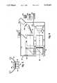
- FIG. 2illustrates the internal structure of each loupe 12 and 14.
- a housing 50is provided with a beam splitting optical cube 52 with a beam splitting interface 54 mounted within the housing 50.
- the beam splitting interface 54preferably provides 50% reflection and 50% transmission which provides optimal scene and viewing brightness.
- the optical fibers 16 or 18 which supply illumination from a source 56are mounted through a support 58 to the housing 50 to direct illumination through a lens system 60 and circular polarizing filter 62 for reflection from a first surface of the beam splitting interface 54 outward through a further, objective lens system 64 to illuminate the field of view 24 or 26. That portion of the radiation, typically 50%, which passes through the beam splitting interface 54 extends onward through the housing 50 to a reflector 66 within the subassemblies 34 or 36 from which it is directed generally to illuminate the field of view 24 or 26 at the location where the surgeon or other operator is to view it.
- Rays from the illuminated image returning from the field of view 24, 26pass back through lens 64 to optical interface 54 where it is transmitted, in part, through the first to the second surface of the interface 54 to a circular polarizing filter 68 and a Pechan/Schmidt roof prism 70 on through eyepiece optics 72 to an eye 30, 32 of the viewer.
- the polarizing filters 62 and 68provide circular polarization which attenuates the radiation only by 20% while transmitting 80%.
- the dimensions of the path between the polarizing filters 62 and 68 for light which causes perceivable brightness or flare at the interface 54 within the cube 52is such that all such illumination is attenuated by the combined polarizations of the filters 62 and 68. Scattering by objects within the field of view 24, 26, however, causes the returning illumination to loose a defined polarization such that the filter 68 is relatively ineffective in attenuating that illumination which in turn passes through the optics 70 and 72 to the viewing eye 30, 32.
- the prism 70provides an erect image and further lengthens the optical path in order to achieve a desired focal length for the telescope formed by objective lens system 64 in combination with eyepiece lenses 72.
- the lens system 60is provided in order to optimize the available illumination from the optical fiber 16, 18 so that it illuminates the same field of view 24, 26, or portion thereof, as seen by the viewer's eye 30, 32.
- an optical camera system 80is attached to a headband 82 of the type known in the art and securely fitted about the head of the operator in such position that it typically lies between loupes 84 and 86 which are positioned, either by eyeglass supports or additionally supported by the headband 82, to permit the operator's eyes 88 and 90 to view respectively therethrough.
- Loupes 84, 86may be of the design described above, other design, or may be omitted entirely.
- the camera 80includes a housing 90 having therein a charge couple device (CCD), video sensor chip 92 and amplifier/driver pc board 93.
- Chip 92responds to the light from a field of view 94 after passing through a beam splitter 96, zoom lens 98 and infrared filter 100 to provide a corresponding video signal that is amplified on the board 93 to drive an output cable 104 to a controller 125 and monitor 126 or other utilization device.
- CCDcharge couple device
- Chip 92responds to the light from a field of view 94 after passing through a beam splitter 96, zoom lens 98 and infrared filter 100 to provide a corresponding video signal that is amplified on the board 93 to drive an output cable 104 to a controller 125 and monitor 126 or other utilization device.
- the field of view 94is illuminated by light from an optical fiber 106 through a lens 108 and reflector 110 which positions the illumination to pass through a zoom lens 112 to be reflected by a reflector 114 from which it is reflected off the beam splitter 96 to travel the same optical axis as viewed by the chip 92 toward the field of view 94.
- Polarizing filters 116 and 118may be provided as described above with respect to FIG. 2 in the path of illumination from the cable 106 and in the viewing path after passing through the beam splitter 96 in order to eliminate from the image processed by the chip 92 all flare from the beam splitter 96 resulting from its illumination by light from the cable 106.
- An absorber 120may additionally be provided so that all radiation passing through the beam splitter 96 from the illuminating light in cable 106 is absorbed and not permitted to reflect within the housing 90 causing further undesirable optical or flare effects.
- a subassembly such as described abovemay alternatively be provided to make use of this waste beam.
- the zoom lenses 98 and 112are typically identical and are coupled either mechanically or electrically by a coupling 122 to vary their focal lengths together.
- a focus control 124is provided remotely, typically at the location of viewing monitor 126 for the video image transmitted by the processor chip 92.
- the use of coordinated zoom lenses 98 and 112permits the region of illumination to track in size the region of view seen by the video sensor chip 92. This in turn provides optimal utilization of the incident illumination.
- a microphone 128is mounted on a suitable surface of the housing 80, such as on the front as shown, and its output is coupled into the cable 104 through the amplifier/driver board 93.
- the audio discussions during the operation or procedureare thus remotely transmitted to controller 125 where they are reproduced by a speaker 129.
- a video cameramay be incorporated into a binocular loupe system as illustrated in FIGS. 5 and 6.
- first and second loupes 130 and 132are provided and supported by a means 134 which may include either eyeglass lenses and/or frames or a separate headband as desired.
- the loupes 130 and 132are positioned, as described above, in coordination with the operator's eyes 136 and 138 to permit optimal viewing of a field of view 140.
- One of the loupes, shown here as loupe 132has associated with it a video camera 142 the design of which, and the associated loupe 132, are more fully described below in FIG. 6.
- the other loupe 130typically is of the design illustrated above in FIG.
- loupes 130 and 132provide viewing by the operator of the field of view 140.
- the loupe 130is additionally constructed to provide illumination along the same axis as is used for viewing while the loupe 132 is constructed to provide video sensing of the image along the same axis as used for viewing.
- loupe 132 and associated camera 142are more fully described. As shown there, viewing of the field of view 140 is accomplished along an optical axis which passes through an objective lens 150, beam splitter 152, Pechan/Schmidt prism 154 and objective lens 156.
- the beam splitter 152has a beam splitting interface 158 which provides an appropriate percentage of transmission and reflection depending upon the sensitivity of the video camera and the matching transmission of the companion loupe 130. Typical transmission reflection percentages would be 50/50.
- the light reflected by the beam splitting interface 158is directed upwards where a reflector 160 redirects it within the video camera portion 142 through an optical system 162 and infrared filter 164 to a video sensor chip 166, also typically a charge coupled device (CCD), to an amplifier/driver 167.
- the video sensor 166converts the received image to a video signal which is applied as an output on a cable 168 by amplifier/driver 167 to a video monitor or otherwise as desired.
- a front mounted microphone 170is also provided and its output is applied through amplifier/driver 167 to the cable 168.
- FIGS. 5 and 6provides both on axis viewing as well as video photography through a single pair of binocular loupes 130 and 132.
Landscapes
- Physics & Mathematics (AREA)
- Health & Medical Sciences (AREA)
- Life Sciences & Earth Sciences (AREA)
- General Physics & Mathematics (AREA)
- Surgery (AREA)
- Optics & Photonics (AREA)
- General Health & Medical Sciences (AREA)
- Heart & Thoracic Surgery (AREA)
- Molecular Biology (AREA)
- Veterinary Medicine (AREA)
- Public Health (AREA)
- Animal Behavior & Ethology (AREA)
- Medical Informatics (AREA)
- Engineering & Computer Science (AREA)
- Biomedical Technology (AREA)
- Ophthalmology & Optometry (AREA)
- Nuclear Medicine, Radiotherapy & Molecular Imaging (AREA)
- Pathology (AREA)
- Oral & Maxillofacial Surgery (AREA)
- Chemical & Material Sciences (AREA)
- Analytical Chemistry (AREA)
- Biophysics (AREA)
- Microscoopes, Condenser (AREA)
Abstract
Description
Claims (8)
Priority Applications (3)
| Application Number | Priority Date | Filing Date | Title |
|---|---|---|---|
| US07/419,761US5078469A (en) | 1989-10-11 | 1989-10-11 | Optical system which allows coincident viewing, illuminating and photographing |
| AU66068/90AAU6606890A (en) | 1989-10-11 | 1990-10-11 | Optical system which allows coincident viewing, illuminating and photographing |
| PCT/US1990/005830WO1991006025A1 (en) | 1989-10-11 | 1990-10-11 | Optical system which allows coincident viewing, illuminating and photographing |
Applications Claiming Priority (1)
| Application Number | Priority Date | Filing Date | Title |
|---|---|---|---|
| US07/419,761US5078469A (en) | 1989-10-11 | 1989-10-11 | Optical system which allows coincident viewing, illuminating and photographing |
Publications (1)
| Publication Number | Publication Date |
|---|---|
| US5078469Atrue US5078469A (en) | 1992-01-07 |
Family
ID=23663650
Family Applications (1)
| Application Number | Title | Priority Date | Filing Date |
|---|---|---|---|
| US07/419,761Expired - Fee RelatedUS5078469A (en) | 1989-10-11 | 1989-10-11 | Optical system which allows coincident viewing, illuminating and photographing |
Country Status (3)
| Country | Link |
|---|---|
| US (1) | US5078469A (en) |
| AU (1) | AU6606890A (en) |
| WO (1) | WO1991006025A1 (en) |
Cited By (32)
| Publication number | Priority date | Publication date | Assignee | Title |
|---|---|---|---|---|
| AT307U1 (en)* | 1994-09-22 | 1995-07-25 | Olympus Austria Ges M B H Olym | MAGNIFYING GLASSES WITH VARIABLE FOCUS AND VARIABLE MAGNIFICATION FACTOR |
| US5528426A (en)* | 1994-07-14 | 1996-06-18 | Tti Medical | Laser block beam splitter for microscopes |
| AU691027B2 (en)* | 1994-09-22 | 1998-05-07 | Life Optics Handel und Vertieb GmbH | Magnifying glass having a variable focus, variable enlargement ratio and automatic parallax correction |
| US5838421A (en)* | 1997-04-03 | 1998-11-17 | Pedack; Henry | Binocular direct opthalmoscope |
| EP0787313A4 (en)* | 1994-10-17 | 1999-04-21 | Univ North Carolina | DEVICE FOR ENLARGING THE OPTICAL TRAVEL LENGTH IN COMPACT IMAGE DISPLAY SYSTEMS |
| US5971540A (en)* | 1996-06-07 | 1999-10-26 | Olympus Austria Gesellschaft | Magnifying spectacles with variable focus, variable magnification factor and automatic parallax compensation |
| US6120145A (en)* | 1999-06-28 | 2000-09-19 | Ld3, Inc. | Surgical loupes apparatus |
| US6667832B2 (en) | 2001-06-11 | 2003-12-23 | Kerr Corporation | Loupe hinge for magnification viewer |
| US6704142B2 (en)* | 1997-12-15 | 2004-03-09 | Kerr Corporation | Magnification viewer |
| US20040070823A1 (en)* | 2002-10-10 | 2004-04-15 | Radna Richard J. | Head-mount recording of three-dimensional stereo video images |
| AT6702U3 (en)* | 2003-09-24 | 2004-07-26 | In Vision Praez Soptik Produkt | STEREOSCOPIC MAGNIFIER |
| BG64807B1 (en)* | 1999-11-24 | 2006-04-28 | Life Optics Handel Und Vertrieb Gmbh | Visual aid in the form of telescopic spectacles with an automatic focussing device |
| US20070103774A1 (en)* | 2005-11-08 | 2007-05-10 | Gary Woker | Locking inter-pupillary distance and convergence adjustment mechanism |
| KR100797546B1 (en) | 2007-06-25 | 2008-01-24 | 주식회사 드림에이스테크 | Thru lens type medical loupe device |
| WO2008127620A1 (en)* | 2007-04-11 | 2008-10-23 | Remicalm, Llc. | Headset mounted apparatus mounting a visor with interchangeable filter sets |
| US20100142045A1 (en)* | 2008-12-08 | 2010-06-10 | Alexsey Mazurenko | Magnification viewer with loupe mounting assembly |
| EP2253263A1 (en) | 2009-05-18 | 2010-11-24 | MB-Technics Gmbh | Portable medical recording device |
| CN103561238A (en)* | 2013-11-07 | 2014-02-05 | 苏州康捷医疗股份有限公司 | Multi-functional low vision aid instrument |
| WO2014076045A3 (en)* | 2012-11-19 | 2014-10-23 | Orangedental Gmbh & Co. Kg | Magnification loupe with display system |
| EP2601550A4 (en)* | 2010-08-05 | 2015-01-28 | Kerr Corp | Variable-magnification optical loupe |
| US20160054560A1 (en)* | 2013-04-28 | 2016-02-25 | Moshe Lior Alkouby | Loupe with attached camera |
| WO2016030873A1 (en)* | 2014-08-25 | 2016-03-03 | Gouri Arie | Loupe with attached camera |
| CN106791345A (en)* | 2015-11-20 | 2017-05-31 | 南京得健福电子科技有限公司 | Hiccough |
| US20190056584A1 (en)* | 2016-03-03 | 2019-02-21 | Guy Davidi | Loupe camera |
| USD884236S1 (en) | 2018-10-04 | 2020-05-12 | Integra Lifesciences Corporation | Wearable headgear device |
| US10724716B2 (en) | 2018-10-04 | 2020-07-28 | Integra Lifesciences Corporation | Head wearable devices and methods |
| USD901737S1 (en) | 2018-10-04 | 2020-11-10 | Integra Lifesciences Corporation | Wearable headgear device |
| US11006093B1 (en) | 2020-01-22 | 2021-05-11 | Photonic Medical Inc. | Open view, multi-modal, calibrated digital loupe with depth sensing |
| US20240027744A1 (en)* | 2021-06-10 | 2024-01-25 | Kondo Labo., Inc. | Head-mounted loupe |
| US12038630B1 (en)* | 2022-11-18 | 2024-07-16 | Designs For Vision, Inc. | Telescopic image capture/recording device |
| US20240369855A1 (en)* | 2022-11-18 | 2024-11-07 | Designs For Vision, Inc. | Examination/visualization/Collection System with Light Enhancement |
| RU2838390C2 (en)* | 2023-06-16 | 2025-04-15 | федеральное государственное бюджетное учреждение "Национальный медицинский исследовательский центр имени В.А. Алмазова" Министерства здравоохранения Российской Федерации | Video-fluorescent device for diagnostics in near infrared range during open operations |
Families Citing this family (3)
| Publication number | Priority date | Publication date | Assignee | Title |
|---|---|---|---|---|
| JPH07501627A (en)* | 1991-11-28 | 1995-02-16 | ザ ユニバーシティ オブ メルボルン | Binocular-shaped bent axis loupe |
| EP2206461B1 (en)* | 2009-01-12 | 2011-10-05 | Andreas Dr. Dr. Tietjen | Method and device for illuminating the microscope field, particularly the eye background, during observation with a stereo silt lamp microscope |
| IT202000000874A1 (en)* | 2020-01-17 | 2021-07-17 | Insmile S R L | DIGITAL MAGNIFYING DEVICE |
Citations (9)
| Publication number | Priority date | Publication date | Assignee | Title |
|---|---|---|---|---|
| US2111187A (en)* | 1934-07-05 | 1938-03-15 | Keeler Charles Henry | Ophthalmoscope |
| US2246817A (en)* | 1937-10-18 | 1941-06-24 | Zeiss Ikon Ag | Photometer |
| US3066569A (en)* | 1958-12-15 | 1962-12-04 | Francis B Macdonald | Line-of-sight illumination and viewing instrument |
| US3586414A (en)* | 1968-05-16 | 1971-06-22 | Sola International Pty Ltd | Binocular viewing device |
| US4196966A (en)* | 1978-05-01 | 1980-04-08 | Malis Leonard I | Binocular magnification system |
| US4516190A (en)* | 1983-12-29 | 1985-05-07 | Luxtec Corporation | Surgical headlamp |
| US4593683A (en)* | 1983-12-03 | 1986-06-10 | Carl-Zeiss-Stiftung | Medical examination instrument with headband support |
| US4704000A (en)* | 1980-08-05 | 1987-11-03 | Research Triangle Institute | Vision enhancing system |
| US4836188A (en)* | 1986-05-06 | 1989-06-06 | Berry Yale J | Instrument for illuminated sterescopic viewing of body cavities |
Family Cites Families (3)
| Publication number | Priority date | Publication date | Assignee | Title |
|---|---|---|---|---|
| US3502888A (en)* | 1967-07-19 | 1970-03-24 | Sylvania Electric Prod | Optical retroreflective label reading systems employing polarized electromagnetic radiation |
| FR2517837A1 (en)* | 1981-12-04 | 1983-06-10 | Anvar | DEVICE OPTIMIZING THE COUPLING OF TWO OPTICAL SYSTEMS FOR OBJECT OBSERVATION AND ANALYSIS |
| JPH0757226B2 (en)* | 1986-10-27 | 1995-06-21 | オリンパス光学工業株式会社 | Surgical microscope |
- 1989
- 1989-10-11USUS07/419,761patent/US5078469A/ennot_activeExpired - Fee Related
- 1990
- 1990-10-11AUAU66068/90Apatent/AU6606890A/ennot_activeAbandoned
- 1990-10-11WOPCT/US1990/005830patent/WO1991006025A1/enunknown
Patent Citations (9)
| Publication number | Priority date | Publication date | Assignee | Title |
|---|---|---|---|---|
| US2111187A (en)* | 1934-07-05 | 1938-03-15 | Keeler Charles Henry | Ophthalmoscope |
| US2246817A (en)* | 1937-10-18 | 1941-06-24 | Zeiss Ikon Ag | Photometer |
| US3066569A (en)* | 1958-12-15 | 1962-12-04 | Francis B Macdonald | Line-of-sight illumination and viewing instrument |
| US3586414A (en)* | 1968-05-16 | 1971-06-22 | Sola International Pty Ltd | Binocular viewing device |
| US4196966A (en)* | 1978-05-01 | 1980-04-08 | Malis Leonard I | Binocular magnification system |
| US4704000A (en)* | 1980-08-05 | 1987-11-03 | Research Triangle Institute | Vision enhancing system |
| US4593683A (en)* | 1983-12-03 | 1986-06-10 | Carl-Zeiss-Stiftung | Medical examination instrument with headband support |
| US4516190A (en)* | 1983-12-29 | 1985-05-07 | Luxtec Corporation | Surgical headlamp |
| US4836188A (en)* | 1986-05-06 | 1989-06-06 | Berry Yale J | Instrument for illuminated sterescopic viewing of body cavities |
Non-Patent Citations (12)
| Title |
|---|
| "A New Dimension in 20/20 Surgical Visualization", 1985 Luxtec Corporation. |
| "Isn't There a Better Way?", Luxtec Videolux, 1987 Luxtec Corporation (#8703). |
| "Luxtec Fiber Optic Cables: Clearly the Best!", 1988 Luxtec Corporation (#8801). |
| "Luxtec Fiber Optic Headlights: Have You Seen the Light?", 1988 Luxtec Corporation (#8803). |
| "Luxtec Fiber Optic Lightsources: Light-Years Ahead", 1988 Luxtec Corporation (#8802). |
| A New Dimension in 20/20 Surgical Visualization , 1985 Luxtec Corporation.* |
| Isn t There a Better Way , Luxtec Videolux, 1987 Luxtec Corporation ( 8703).* |
| Luxtec Corporation brochure, "Illuminating Magnifying Extending and Audio/Video Recording of the Surgeon's Vision" with Product Ordering and Customer Information and including the following brochures: |
| Luxtec Corporation brochure, Illuminating Magnifying Extending and Audio/Video Recording of the Surgeon s Vision with Product Ordering and Customer Information and including the following brochures:* |
| Luxtec Fiber Optic Cables: Clearly the Best , 1988 Luxtec Corporation ( 8801).* |
| Luxtec Fiber Optic Headlights: Have You Seen the Light , 1988 Luxtec Corporation ( 8803).* |
| Luxtec Fiber Optic Lightsources: Light Years Ahead , 1988 Luxtec Corporation ( 8802).* |
Cited By (57)
| Publication number | Priority date | Publication date | Assignee | Title |
|---|---|---|---|---|
| US5528426A (en)* | 1994-07-14 | 1996-06-18 | Tti Medical | Laser block beam splitter for microscopes |
| AU691027B2 (en)* | 1994-09-22 | 1998-05-07 | Life Optics Handel und Vertieb GmbH | Magnifying glass having a variable focus, variable enlargement ratio and automatic parallax correction |
| AT307U1 (en)* | 1994-09-22 | 1995-07-25 | Olympus Austria Ges M B H Olym | MAGNIFYING GLASSES WITH VARIABLE FOCUS AND VARIABLE MAGNIFICATION FACTOR |
| EP0787313A4 (en)* | 1994-10-17 | 1999-04-21 | Univ North Carolina | DEVICE FOR ENLARGING THE OPTICAL TRAVEL LENGTH IN COMPACT IMAGE DISPLAY SYSTEMS |
| US5971540A (en)* | 1996-06-07 | 1999-10-26 | Olympus Austria Gesellschaft | Magnifying spectacles with variable focus, variable magnification factor and automatic parallax compensation |
| US5838421A (en)* | 1997-04-03 | 1998-11-17 | Pedack; Henry | Binocular direct opthalmoscope |
| US20040125444A1 (en)* | 1997-12-15 | 2004-07-01 | Kerr Corporation | Magnification viewer |
| US6704142B2 (en)* | 1997-12-15 | 2004-03-09 | Kerr Corporation | Magnification viewer |
| EP1073924A4 (en)* | 1998-04-20 | 2005-06-15 | Kerr Corp | Magnification viewer |
| US6120145A (en)* | 1999-06-28 | 2000-09-19 | Ld3, Inc. | Surgical loupes apparatus |
| BG64807B1 (en)* | 1999-11-24 | 2006-04-28 | Life Optics Handel Und Vertrieb Gmbh | Visual aid in the form of telescopic spectacles with an automatic focussing device |
| US7286287B1 (en) | 1999-11-24 | 2007-10-23 | Life Optics Gmbh | Visual aid in the form of telescopic spectacles with an automated focusing device |
| US6667832B2 (en) | 2001-06-11 | 2003-12-23 | Kerr Corporation | Loupe hinge for magnification viewer |
| US20040070823A1 (en)* | 2002-10-10 | 2004-04-15 | Radna Richard J. | Head-mount recording of three-dimensional stereo video images |
| AT6702U3 (en)* | 2003-09-24 | 2004-07-26 | In Vision Praez Soptik Produkt | STEREOSCOPIC MAGNIFIER |
| US20070103774A1 (en)* | 2005-11-08 | 2007-05-10 | Gary Woker | Locking inter-pupillary distance and convergence adjustment mechanism |
| US7675678B2 (en) | 2005-11-08 | 2010-03-09 | Perioptix | Locking inter-pupillary distance and convergence adjustment mechanism |
| GB2460377A (en)* | 2007-04-11 | 2009-12-02 | Remicalm Llc | Headset mounted apparatus mounting a visor with interchangeable filter sets |
| WO2008127620A1 (en)* | 2007-04-11 | 2008-10-23 | Remicalm, Llc. | Headset mounted apparatus mounting a visor with interchangeable filter sets |
| GB2460377B (en)* | 2007-04-11 | 2012-03-07 | Remicalm Llc | Headset mounted apparatus mounting a visor with interchangeable filter sets |
| KR100797546B1 (en) | 2007-06-25 | 2008-01-24 | 주식회사 드림에이스테크 | Thru lens type medical loupe device |
| US20100142045A1 (en)* | 2008-12-08 | 2010-06-10 | Alexsey Mazurenko | Magnification viewer with loupe mounting assembly |
| US7891808B2 (en) | 2008-12-08 | 2011-02-22 | Alexsey Mazurenko | Magnification viewer with loupe mounting assembly |
| EP2253263A1 (en) | 2009-05-18 | 2010-11-24 | MB-Technics Gmbh | Portable medical recording device |
| EP2601550A4 (en)* | 2010-08-05 | 2015-01-28 | Kerr Corp | Variable-magnification optical loupe |
| CN104813219A (en)* | 2012-11-19 | 2015-07-29 | 橙子牙科有限两合公司 | Magnification loupe with display system |
| WO2014076045A3 (en)* | 2012-11-19 | 2014-10-23 | Orangedental Gmbh & Co. Kg | Magnification loupe with display system |
| US20160054560A1 (en)* | 2013-04-28 | 2016-02-25 | Moshe Lior Alkouby | Loupe with attached camera |
| CN103561238A (en)* | 2013-11-07 | 2014-02-05 | 苏州康捷医疗股份有限公司 | Multi-functional low vision aid instrument |
| WO2016030873A1 (en)* | 2014-08-25 | 2016-03-03 | Gouri Arie | Loupe with attached camera |
| CN106791345A (en)* | 2015-11-20 | 2017-05-31 | 南京得健福电子科技有限公司 | Hiccough |
| US10698196B2 (en)* | 2016-03-03 | 2020-06-30 | Guy Davidi | Loupe camera |
| US20190056584A1 (en)* | 2016-03-03 | 2019-02-21 | Guy Davidi | Loupe camera |
| US11268686B2 (en) | 2018-10-04 | 2022-03-08 | Integra Lifesciences Corporation | Head wearable devices and methods |
| US11555605B2 (en) | 2018-10-04 | 2023-01-17 | Integra Lifesciences Corporation | Head wearable devices and methods |
| US10830428B2 (en) | 2018-10-04 | 2020-11-10 | Integra Lifesciences Corporation | Head wearable devices and methods |
| USD901737S1 (en) | 2018-10-04 | 2020-11-10 | Integra Lifesciences Corporation | Wearable headgear device |
| US11835211B2 (en) | 2018-10-04 | 2023-12-05 | Integra Lifesciences Corporation | Head wearable devices and methods |
| US11067267B2 (en) | 2018-10-04 | 2021-07-20 | Integra Lifesciences Corporation | Head wearable devices and methods |
| USD935074S1 (en) | 2018-10-04 | 2021-11-02 | Integra Lifesciences Corporation | Wearable headgear device |
| US11674681B2 (en) | 2018-10-04 | 2023-06-13 | Integra Lifesciences Corporation | Head wearable devices and methods |
| US11255533B2 (en) | 2018-10-04 | 2022-02-22 | Integra Lifesciences Corporation | Head wearable devices and methods |
| USD884236S1 (en) | 2018-10-04 | 2020-05-12 | Integra Lifesciences Corporation | Wearable headgear device |
| USD987145S1 (en) | 2018-10-04 | 2023-05-23 | Integra Lifesciences Corporation | Wearable headgear device |
| US10724716B2 (en) | 2018-10-04 | 2020-07-28 | Integra Lifesciences Corporation | Head wearable devices and methods |
| US11635198B2 (en) | 2018-10-04 | 2023-04-25 | Integra Lifesciences Corporation | Head wearable devices and methods |
| US11611735B2 (en) | 2020-01-22 | 2023-03-21 | Photonic Medical Inc. | Open view, multi-modal, calibrated digital loupe with depth sensing |
| US11412202B2 (en) | 2020-01-22 | 2022-08-09 | Photonic Medical Inc. | Open view, multi-modal, calibrated digital loupe with depth sensing |
| US11166006B2 (en) | 2020-01-22 | 2021-11-02 | Photonic Medical Inc. | Open view, multi-modal, calibrated digital loupe with depth sensing |
| US11006093B1 (en) | 2020-01-22 | 2021-05-11 | Photonic Medical Inc. | Open view, multi-modal, calibrated digital loupe with depth sensing |
| US12075019B2 (en) | 2020-01-22 | 2024-08-27 | Photonic Medical Inc. | Open view, multi-modal, calibrated digital loupe with depth sensing |
| US20240027744A1 (en)* | 2021-06-10 | 2024-01-25 | Kondo Labo., Inc. | Head-mounted loupe |
| US12038630B1 (en)* | 2022-11-18 | 2024-07-16 | Designs For Vision, Inc. | Telescopic image capture/recording device |
| US20240255780A1 (en)* | 2022-11-18 | 2024-08-01 | Designs For Vision, Inc. | Telescopic Image Capture/Recording Device |
| US20240369855A1 (en)* | 2022-11-18 | 2024-11-07 | Designs For Vision, Inc. | Examination/visualization/Collection System with Light Enhancement |
| US12332507B2 (en)* | 2022-11-18 | 2025-06-17 | Designs For Vision, Inc. | Examination/visualization/collection system with light enhancement |
| RU2838390C2 (en)* | 2023-06-16 | 2025-04-15 | федеральное государственное бюджетное учреждение "Национальный медицинский исследовательский центр имени В.А. Алмазова" Министерства здравоохранения Российской Федерации | Video-fluorescent device for diagnostics in near infrared range during open operations |
Also Published As
| Publication number | Publication date |
|---|---|
| WO1991006025A1 (en) | 1991-05-02 |
| AU6606890A (en) | 1991-05-16 |
Similar Documents
| Publication | Publication Date | Title |
|---|---|---|
| US5078469A (en) | Optical system which allows coincident viewing, illuminating and photographing | |
| JP3429320B2 (en) | Image combining system for eyeglasses and face mask | |
| US4023189A (en) | Wide angle fundus illumination and photography apparatus | |
| US5497266A (en) | Telescopic day and night sight | |
| US5042930A (en) | Optical system which allows coincident viewing, illuminating and photographing | |
| US4653879A (en) | Compact see-through night vision goggles | |
| US6204974B1 (en) | Compact image display system for eyeglasses or other head-borne frames | |
| CA1318528C (en) | Compact see-through night vision goggles | |
| US6224227B1 (en) | Surgical headlight assembly with detachable video-camera module | |
| US6546208B1 (en) | Stereoscopic telescope with camera | |
| US4237492A (en) | Image observation apparatus | |
| US6061182A (en) | Combiner for superimposing a display image on to an image of an external scene | |
| GB2006463A (en) | Holographic one tube goggle | |
| EP1808722A2 (en) | Image Combining System for Eyeglasses and Face Masks | |
| EP0577268B1 (en) | Optical system | |
| US5742434A (en) | Adapter for extracting a portion of an image from an optical system or device | |
| EP0547232A4 (en) | Magnifying observation apparatus | |
| US5018846A (en) | Microscope | |
| US4249797A (en) | Dual image viewer with mirror adjusting means | |
| CA1270131A (en) | Method and apparatus for simultaneously observing a transparent object from two directions | |
| JPH05249368A (en) | Device for deciding visual field part viewed by eyes of observer | |
| US5703643A (en) | Sight-tracking viewing device | |
| JPH11215411A (en) | Optical flux separate means and observation optical system using the same | |
| IL121042A (en) | Combiner for superimposing an image onto an external scene | |
| RU2052921C1 (en) | VIEWFINDER |
Legal Events
| Date | Code | Title | Description |
|---|---|---|---|
| AS | Assignment | Owner name:LUXTEC CORPORATION, TECHNOLOGY PARK, A CORP. OF MA Free format text:ASSIGNMENT OF ASSIGNORS INTEREST.;ASSIGNORS:CLARK, BERNARD;WU, DAU;REEL/FRAME:005281/0870;SIGNING DATES FROM 19900320 TO 19900416 | |
| FEPP | Fee payment procedure | Free format text:PAYOR NUMBER ASSIGNED (ORIGINAL EVENT CODE: ASPN); ENTITY STATUS OF PATENT OWNER: SMALL ENTITY | |
| FPAY | Fee payment | Year of fee payment:4 | |
| AS | Assignment | Owner name:FIRST NATIONAL BANK OF BOSTON, THE, MASSACHUSETTS Free format text:ASSIGNMENT OF ASSIGNORS INTEREST;ASSIGNOR:LUXTEC CORPORATION;REEL/FRAME:007833/0347 Effective date:19951024 | |
| REMI | Maintenance fee reminder mailed | ||
| LAPS | Lapse for failure to pay maintenance fees | ||
| FP | Lapsed due to failure to pay maintenance fee | Effective date:20000107 | |
| AS | Assignment | Owner name:ARK CLO 2000-1, LIMITED, NEW YORK Free format text:ASSIGNMENT OF ASSIGNORS INTEREST;ASSIGNOR:FLEET NATIONAL BANK;REEL/FRAME:011828/0646 Effective date:20010301 | |
| AS | Assignment | Owner name:PRIME SOURCE HEALTHCARE, INC., ARIZONA Free format text:RELEASE BY SECURED PARTY;ASSIGNOR:ARK CLO 2000-1, LIMITED;REEL/FRAME:014277/0240 Effective date:20040114 | |
| STCH | Information on status: patent discontinuation | Free format text:PATENT EXPIRED DUE TO NONPAYMENT OF MAINTENANCE FEES UNDER 37 CFR 1.362 |