US5078016A - Two piece load cell pin - Google Patents
Two piece load cell pinDownload PDFInfo
- Publication number
- US5078016A US5078016AUS07/619,958US61995890AUS5078016AUS 5078016 AUS5078016 AUS 5078016AUS 61995890 AUS61995890 AUS 61995890AUS 5078016 AUS5078016 AUS 5078016A
- Authority
- US
- United States
- Prior art keywords
- pivot pin
- load cell
- strain gauge
- sleeve
- gauge means
- Prior art date
- Legal status (The legal status is an assumption and is not a legal conclusion. Google has not performed a legal analysis and makes no representation as to the accuracy of the status listed.)
- Expired - Fee Related
Links
- 238000005259measurementMethods0.000claimsdescription3
- 210000004027cellAnatomy0.000description38
- 230000007246mechanismEffects0.000description6
- 229910000831SteelInorganic materials0.000description5
- 239000010959steelSubstances0.000description5
- 238000003780insertionMethods0.000description4
- 230000037431insertionEffects0.000description4
- 230000009471actionEffects0.000description3
- 230000000712assemblyEffects0.000description3
- 238000000429assemblyMethods0.000description3
- 230000000295complement effectEffects0.000description3
- 230000008859changeEffects0.000description2
- 238000009749continuous castingMethods0.000description2
- 230000008439repair processEffects0.000description2
- 230000000717retained effectEffects0.000description2
- 230000006978adaptationEffects0.000description1
- 238000013461designMethods0.000description1
- 238000006073displacement reactionMethods0.000description1
- 230000007257malfunctionEffects0.000description1
- 238000000034methodMethods0.000description1
- 230000004048modificationEffects0.000description1
- 238000012986modificationMethods0.000description1
- 230000008569processEffects0.000description1
- 230000001681protective effectEffects0.000description1
Images


Classifications
- B—PERFORMING OPERATIONS; TRANSPORTING
- B22—CASTING; POWDER METALLURGY
- B22D—CASTING OF METALS; CASTING OF OTHER SUBSTANCES BY THE SAME PROCESSES OR DEVICES
- B22D11/00—Continuous casting of metals, i.e. casting in indefinite lengths
- B22D11/04—Continuous casting of metals, i.e. casting in indefinite lengths into open-ended moulds
- B22D11/053—Means for oscillating the moulds
Definitions
- This inventionrelates to a pivot pin assembly for insertion into a pivot joint and including a strain gauge means for detecting loads applied to the pivot joint.
- Load cells capable of sensing and measuring forcesare known in the art. Force measurement may be accomplished by using a strain gauge which converts mechanical motion to an electrical signal. By forming a pattern of resistor elements on the exterior surface of a load sensing device, deformation of the device as a result of applied load can be measured as a function of the change in resistance of the resistor elements as they are stretched or compressed. The change in resistance is measured by a Wheatstone bridge circuit which may be formed on the surface of the load sensing device.
- Yet another object of this inventionis to provide a dumbbell shaped load cell for insertion inside a tubular sleeve in a pivot joint.
- Still another object of the present inventionis to provide a load cell of a shape which is complementary to the interior of the sleeve such that a frictional contacting fit is obtained between the outside walls of the load cell and the interior of the tubular sleeve.
- the pivot pin of this inventionis directed to a dumbbell shaped portion with strain gauges mounted thereon and designed for insertion inside a protective tubular sleeve.
- the pinis designed for insertion into a pivot point connection of machinery so that dynamic loads and stresses placed on the pivot point can be measured.
- the dumbbell shapeallows strain gauges to be mounted in recessed areas so that forces applied to the pivot pin are not applied directly to the strain gauge surface.
- the two piece design of the pivot pinallows the dumbbell shaped portion and strain gauges to be removed for repair or replacement leaving the tubular sleeve in place thereby leaving the pivot bearings undisturbed.
- FIG. 1is a top elevation of a continuous caster vibrating assembly, portions of which are broken away showing in cross section the continuous caster mounting assembly and part of the vibrating mechanism and showing a cross bar of indeterminant length;
- FIG. 2is a side elevation of the continuous caster vibrating mechanism shown in FIG. 1;
- FIG. 3is an enlarged fragmentary side elevation of the continuous caster mold table with a portion of the covering plate broken away to show the interior mechanism;
- FIG. 4is a cross-sectional view of the pivot pin assembly as installed in a pivot joint of a continuous caster
- FIG. 5is a side elevation of the dumbbell shaped portion of the pivot pin assembly
- FIG. 6is a side elevation of the sleeve portion of the pivot pin assembly
- FIGS. 7 and 8are side elevations of the end caps used in retaining the pivot pin in the pivot joint
- FIG. 9is a side elevation of the dumbbell shaped portion of the pivot pin assembly and showing a series of strain gauges attached thereto.
- FIGS. 1-2a vibrating mechanism V of a continuous casting assembly is shown and will be described in detail.
- molten steelis poured into the mold 2, mold table 4 supports mold 2 and is in turn supported by a pair of lever arms 6 and 8 at each end thereof by connection of pivot pins 10 and 12.
- Lever arms 6 and 8are pivotally supported at ends 14 and 16, respectively.
- the vibrating mechanism Vwhich consists of, as best shown in FIG. 1, a generator 18 connected to an eccentric oscillator 20 which provides a shaking action to bar 22 which is attached to cross bar 24 so that the vibrating action may be imparted to both lever arms 6 and 8.
- the connection between cross bar 24 and lever arms 6 and 8transfers the vibrating motion from a horizontal plane to a vertical plane.
- L-shaped pivoted member 26as best shown in FIG. 2, includes pivot points at each end 28 and 30 and at central location 32.
- the horizontal movement of bar 22correspondingly imparts a horizontal motion to pivot point 28 and is transformed to a vertical motion at pivot point 30 by L-shaped member 26.
- Vertical post 34is pivotally connected at each end at pivot points 30 and 36.
- the vertical vibration of pivot point 30causes post 34 to impart a vertical vibrating action at pivot point 36, thereby vertically vibrating lever arm 6.
- the vertical vibration on lever arm 6causes a vibration in mold 2 and prevents the molten steel from adhering to its walls. In order to keep mold 2 in horizontally level orientation, it is necessary to provide pivot pin assemblies 10 and 12 where mold table 4 is pivotally connected to lever arms 6 and 8, respectively.
- lever arm 6supports mold table 4 by connection at pivot pin assembly 12.
- a portion of the exterior casing 38has been broken away to reveal the support structure of mold table 4 which keeps the bottom wall of mold 2 horizontal when lever arm 6 is vertically vibrating mold table 4.
- the arm 6travels in a short arcuate path at pivot point 36. Since the path is arcuate, it is necessary to have pivot pin assemblies 10 and 12 to allow mold table 4 to pivot so that mold 2 only moves vertically.
- guide rollers 40 and 42 and guides 44 and 46are used in combination with mold table 4.
- Guide rollers 40 and 42are anchored independently of mold table 4 in order that mold table attached guides 44 and 46 are allowed to move only in a vertical direction and are restrained from horizontal movement by guide rollers 40 and 42, respectively.
- guide roller 40includes two rollers 48 and 50 connected for pivotal movement by rigid support member 52 which is anchored at 54.
- Guide 44has a smooth vertical surface which contacts rollers 48 and 50 as mold table 4 vibrates up and down and prevents side to side motion of mold table 4. As rollers 40 and 42 and guides 44 and 46 wear out, additional vibrations occur. These vibrations cause additional stresses on pivot pin assemblies 10 and 12 which can be measured.
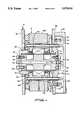
- FIG. 4is a cross sectional view of pivot pin assembly 12 providing a pivotal connection between lever arm 6 and mold table 4.
- Pivot pin assembly 12is surrounded by mold table 4 and extends axially between lever arm walls 56 and 58. Mold table 4 rests on and is supported by pivot pin assembly 12. Each end of pivot pin assembly 12 rests on lever arm walls 56 and 58 such that mold table 4 does not come in contact with lever arm 6.
- the pivot pin assembly 12includes a dumbbell shaped load cell 60 as best shown in FIG. 5.
- Load cell 60includes a pair of end sections 62 and 64 and a middle section 66. End sections 62 and 64 are nearly equal in thickness and middle section 66 is thicker than end sections 62 and 64. Each of end sections 62 and 64 is joined to middle section 66 by portions 68 and 70, respectively, of smaller dimension than end sections 62 and 64 and middle section 66. Portions 68 and 70 are of reduced dimension to provide areas which will not be subjected to directly applied surface loads.
- Cavity 72is located along a longitudinal axis through load cell 60.
- Sections 62 and 64 and 66 and portions 68 and 70may be of any cross sectional geometrical shape which corresponds to the inside surface shape of sleeve 76 as shown in FIG. 6.
- the preferred cross sectional shape of load cell 60 and inside surface 74 of sleeve 76is circular.
- Sleeve 76encloses a hollow interior 78 bounded by interior surface 74.
- Hollow interior 78may be of uniform diameter from one end 80 of sleeve 76 to the other end 82 of sleeve 76, but preferably, inside surface 74 of sleeve 76 is tapered such that a hollow interior 78 is formed which has a larger diameter at end 80 and a smaller diameter at other end 82.
- Outside surface 84 of sleeve 76is of uniform diameter from end 80 to other end 82 of sleeve 76.
- Load cell 60may be formed having a constant uniform diameter of individual sections 62 and 64 and 66 corresponding to interior 78 when interior 78 is of constant uniform diameter such that, load cell 60 may be inserted into sleeve 76 and a close fit is obtained between inside surface 74 and load cell sections 62 and 64 and 66.
- load cell sections 62 and 64 and 66are tapered to correspond to a tapered inside surface 74 of sleeve 76.
- outside wall 86 of load cell end section 62will be of a larger cross sectional diameter than outside wall 88 of load cell end section 64 and each of load cell sections 62 and 64 and 66 are gradually tapered such that a uniform taper occurs between outside wall 86 and outside wall 88 and the outside surfaces 90 and 92 and 94 of load cell sections 62 and 64 and 66, respectively, entirely contact inside surface 74 when load cell 60 is fully inserted into sleeve 76.
- Strain gauges 96are mounted on portions 68 and 70 at locations which allow stresses applied to the load cell to be measured. For example, friction between mold 2 and the molten steel causes stresses on load cell 60 which can be measured. Electrical connection devices 98, such as wires, extend from strain gauges 96 and into holes 100 which provide a passage to cavity 72. Cavity 72 provides a conduit through which the electrical connection devices 98 can extend to a power supply and a readout device (not shown). To prevent electrical connection devices 98 from being accidentally disconnected from strain gauges 96, straps 102 are provided to secure electrical connection devices 98 to portions 68 and 70. Strain gauges 96 are arranged such that axial forces on portions 68 and 70 can be detected.
- strain gauges 96may be used depending on the accuracy of the measurement desired. Preferably, at least two strain gauges 96 spaced 90 degrees apart are located on each portion 68 and 70. Extra strain gauges 96 may be applied to provide spares when a regular strain gauge malfunctions.
- End caps 104 and 106are best shown in FIGS. 7 and 8, respectively.
- End cap 104includes mounting holes 108 which correspond to threaded mounting holes 110 disposed on end section 62. Bolts 112 extend through end cap holes 108 to engage with threaded end section holes 110 to securely attach end cap 104 to load cell 60 as best shown in FIG. 4.
- Cap 104also includes central opening 114 which allows passage of the electrical connection devices 98 extending from strain gauges 96 to pass out of cavity 72 to be connected with a readout device (not shown).
- a conduit connector 116 having an insulated throatis inserted in central opening 114 to prevent chafing of electrical connection devices 98.
- End cap 106includes mounting holes 118 of complementary orientation to threaded end section holes 120 of end section 64. Bolts 122 connect end cap 106 to load cell 60 by passing through mounting holes 118 and threadably attaching to end section holes 120.
- FIG. 4shows a cross sectional view of pivot pin assembly 12 installed to provide a pivotal connection between lever arm 6 and mold table 4.
- Pivot pin assembly 12extends between walls 56 and 58 of lever arm 6.
- Lever arm wall 56includes an opening 124 which encircles load cell end section 64.
- Lever arm wall 58includes an opening 126 which encircles load cell end section 62.
- Mold table 4includes a central section 128 insertable between lever arm walls 56 and 58 and is spaced therefrom such that central section 128 does not contact lever arm walls 56 and 58. Mold table section 128 is entirely supported by pivot pin assembly 12.
- a plurality of bearings 130 and 132encircle pivot pin assembly 12 and support mold table central section 128 for pivotal movement relative to pin assembly 12 and lever arm 6.
- Bearings 130 and 132are retained in position between sleeve 76 and mold table central section 128 by wedge-shaped member 134 and bearing support member 136.
- Bearing support member 136 and wedge-shaped member 134are retained in position relative to each other by an elongated bolts 138.
- Bolts 138extend through cap member 104 and are spaced therefrom as they pass through enlarged openings 140 which allow for movement when lever arm 6 is vibrating mold table 4.
- Sleeve 76operates to retain bearings 130 and 132 in position when load cell 60 is removed for repair or replacement.
- Bolts 142pass through holes 144 in lever arm wall 58 and also pass through holes 146 in end cap 104 and are fastened by nuts 148 to join end cap 104 to lever arm wall 58.
- Bolts 150are inserted into threaded openings 152 and bear against lever arm wall 58 when being screwed into holes 152 to force end cap 104 away from lever arm wall 58 when removal of load cell 60 is desired.
- load cell 60When it is desired to remove load cell 60 from sleeve 76, threaded bolts 122 are removed from load cell 60 and nut 148 is removed from bolt 142, then bolt 150 is screwed in to bear against lever arm wall 58 and force end cap 104 away from lever arm wall 58, then load cell 60 can be removed from sleeve 76.
- load cell 60When using a tapered configuration of load cell 60 complementary to a tapered hollow interior 78 of sleeve 76, wherein end 62 is larger in diameter than end 64, once the frictional contact between inside surface 74 and load cell surfaces 90 and 92 and 94 is broken, load cell 60 may be easily removed from sleeve 76.
- Casing 154is a covering for protecting electrical connection devices 98 as they extend through central opening 114 of end cap 104.
- pivot pin assemblyhas been described as being used in a continuous caster vibrator mechanism V, the pivot pin assembly may be applied in other pivot joints in which it is necessary or desirable to measure stresses from loads applied thereon.
Landscapes
- Engineering & Computer Science (AREA)
- Mechanical Engineering (AREA)
- Force Measurement Appropriate To Specific Purposes (AREA)
Abstract
Description
Claims (15)
Priority Applications (1)
| Application Number | Priority Date | Filing Date | Title |
|---|---|---|---|
| US07/619,958US5078016A (en) | 1989-06-14 | 1990-11-30 | Two piece load cell pin |
Applications Claiming Priority (2)
| Application Number | Priority Date | Filing Date | Title |
|---|---|---|---|
| US07/365,819US5014393A (en) | 1989-06-14 | 1989-06-14 | Vibrating mold assembly |
| US07/619,958US5078016A (en) | 1989-06-14 | 1990-11-30 | Two piece load cell pin |
Related Parent Applications (1)
| Application Number | Title | Priority Date | Filing Date |
|---|---|---|---|
| US07/365,819DivisionUS5014393A (en) | 1989-06-14 | 1989-06-14 | Vibrating mold assembly |
Publications (1)
| Publication Number | Publication Date |
|---|---|
| US5078016Atrue US5078016A (en) | 1992-01-07 |
Family
ID=27003108
Family Applications (1)
| Application Number | Title | Priority Date | Filing Date |
|---|---|---|---|
| US07/619,958Expired - Fee RelatedUS5078016A (en) | 1989-06-14 | 1990-11-30 | Two piece load cell pin |
Country Status (1)
| Country | Link |
|---|---|
| US (1) | US5078016A (en) |
Cited By (3)
| Publication number | Priority date | Publication date | Assignee | Title |
|---|---|---|---|---|
| US6532830B1 (en)* | 1999-09-20 | 2003-03-18 | Ut-Battelle, Llc | High payload six-axis load sensor |
| WO2016001668A1 (en)* | 2014-07-01 | 2016-01-07 | Flintstone Technology Limited | Sensing device |
| US20210197083A1 (en)* | 2019-12-31 | 2021-07-01 | Logitech Europe S.A. | Gaming pedal assembly |
Citations (8)
| Publication number | Priority date | Publication date | Assignee | Title |
|---|---|---|---|---|
| US3695096A (en)* | 1970-04-20 | 1972-10-03 | Ali Umit Kutsay | Strain detecting load cell |
| US3754610A (en)* | 1971-07-29 | 1973-08-28 | Torrid Corp | Load cell |
| US3827514A (en)* | 1973-06-25 | 1974-08-06 | Weigh Tronix | Weight measuring hook block apparatus for cranes |
| US3857452A (en)* | 1974-02-14 | 1974-12-31 | Tri Coastal Ind Inc | Dump truck load-sensing assembly |
| US3992934A (en)* | 1974-04-26 | 1976-11-23 | Strainstall Limited | Mooring device |
| GB1577341A (en)* | 1978-02-20 | 1980-10-22 | British Hovercraft Corp Ltd | Shear pin load cell load measuring equipment |
| US4421186A (en)* | 1980-08-25 | 1983-12-20 | Weigh-Tronix, Inc. | Fork lift scale |
| US4576053A (en)* | 1984-03-20 | 1986-03-18 | Yotaro Hatamura | Load detector |
- 1990
- 1990-11-30USUS07/619,958patent/US5078016A/ennot_activeExpired - Fee Related
Patent Citations (8)
| Publication number | Priority date | Publication date | Assignee | Title |
|---|---|---|---|---|
| US3695096A (en)* | 1970-04-20 | 1972-10-03 | Ali Umit Kutsay | Strain detecting load cell |
| US3754610A (en)* | 1971-07-29 | 1973-08-28 | Torrid Corp | Load cell |
| US3827514A (en)* | 1973-06-25 | 1974-08-06 | Weigh Tronix | Weight measuring hook block apparatus for cranes |
| US3857452A (en)* | 1974-02-14 | 1974-12-31 | Tri Coastal Ind Inc | Dump truck load-sensing assembly |
| US3992934A (en)* | 1974-04-26 | 1976-11-23 | Strainstall Limited | Mooring device |
| GB1577341A (en)* | 1978-02-20 | 1980-10-22 | British Hovercraft Corp Ltd | Shear pin load cell load measuring equipment |
| US4421186A (en)* | 1980-08-25 | 1983-12-20 | Weigh-Tronix, Inc. | Fork lift scale |
| US4576053A (en)* | 1984-03-20 | 1986-03-18 | Yotaro Hatamura | Load detector |
Cited By (4)
| Publication number | Priority date | Publication date | Assignee | Title |
|---|---|---|---|---|
| US6532830B1 (en)* | 1999-09-20 | 2003-03-18 | Ut-Battelle, Llc | High payload six-axis load sensor |
| WO2016001668A1 (en)* | 2014-07-01 | 2016-01-07 | Flintstone Technology Limited | Sensing device |
| US20210197083A1 (en)* | 2019-12-31 | 2021-07-01 | Logitech Europe S.A. | Gaming pedal assembly |
| US11090559B2 (en)* | 2019-12-31 | 2021-08-17 | Logitech Europe S.A. | Gaming pedal assembly |
Similar Documents
| Publication | Publication Date | Title |
|---|---|---|
| US4899599A (en) | Strain force sensor means | |
| CN100498245C (en) | Weighing module | |
| US4326424A (en) | Web tension transducer arrangement | |
| US6122978A (en) | Web tension cantilever transducer apparatus | |
| CN201047775Y (en) | Weighing module | |
| US4796474A (en) | Web tension transducer apparatus | |
| US5777240A (en) | Load cell and load cell beam assembly | |
| US4037469A (en) | Force measuring apparatus | |
| US4666006A (en) | Weighing structure with variable moment load cells | |
| JPS61270622A (en) | Mass and force measuring device | |
| US4735102A (en) | Web tension transducer apparatus | |
| US5078016A (en) | Two piece load cell pin | |
| DE3865397D1 (en) | MEASURING SENSOR FOR MEASURING THE TRAIN TENSION. | |
| US20080115590A1 (en) | Measuring a Tensile Force | |
| US5014393A (en) | Vibrating mold assembly | |
| US4433586A (en) | Electronic cable load gauge | |
| US6845564B2 (en) | Level monitoring sensor apparatus, solid structure sensor apparatus, and pendulum sensor apparatus | |
| CA2151248A1 (en) | Nonthreaded load sensing probe | |
| EP3321223B1 (en) | Load cell | |
| KR100403789B1 (en) | Cable Tension Measurement Device | |
| CA2040658A1 (en) | Load sensing assembly | |
| US3390575A (en) | Adjustable transducer mount | |
| CN117266266A (en) | Bridge foundation subsides deformation monitoring devices | |
| CN214748590U (en) | Cable gravity sensor | |
| JP3268450B2 (en) | Cantilever transducer |
Legal Events
| Date | Code | Title | Description |
|---|---|---|---|
| FPAY | Fee payment | Year of fee payment:4 | |
| FEPP | Fee payment procedure | Free format text:PAYOR NUMBER ASSIGNED (ORIGINAL EVENT CODE: ASPN); ENTITY STATUS OF PATENT OWNER: LARGE ENTITY | |
| FPAY | Fee payment | Year of fee payment:8 | |
| AS | Assignment | Owner name:ISG TECHNOLOGIES, INC., OHIO Free format text:ASSIGNMENT OF ASSIGNORS INTEREST;ASSIGNOR:BETHLEHEM STEEL CORPORATION;REEL/FRAME:014033/0881 Effective date:20030506 | |
| AS | Assignment | Owner name:CIT GROUP/BUSINESS CREDIT, INC., AS COLLATERAL AGE Free format text:PLEDGE AND SECURITY AGREEMENT;ASSIGNOR:INTERNATIONAL STEEL GROUP, INC.;REEL/FRAME:013663/0415 Effective date:20030507 | |
| REMI | Maintenance fee reminder mailed | ||
| LAPS | Lapse for failure to pay maintenance fees | ||
| STCH | Information on status: patent discontinuation | Free format text:PATENT EXPIRED DUE TO NONPAYMENT OF MAINTENANCE FEES UNDER 37 CFR 1.362 | |
| FP | Lapsed due to failure to pay maintenance fee | Effective date:20030107 | |
| AS | Assignment | Owner name:ISG CLEVELAND WORKS RAILWAY COMPANY, OHIO Free format text:RELEASE BY SECURED PARTY;ASSIGNOR:THE CIT GROUP/BUSINESS CREDIT, INC., AS COLLATERAL AGENT;REEL/FRAME:019432/0170 Effective date:20070613 Owner name:ISG/EGL HOLDING COMPANY, OHIO Free format text:RELEASE BY SECURED PARTY;ASSIGNOR:THE CIT GROUP/BUSINESS CREDIT, INC., AS COLLATERAL AGENT;REEL/FRAME:019432/0170 Effective date:20070613 Owner name:ISG TECHNOLOGIES, INC., OHIO Free format text:RELEASE BY SECURED PARTY;ASSIGNOR:THE CIT GROUP/BUSINESS CREDIT, INC., AS COLLATERAL AGENT;REEL/FRAME:019432/0170 Effective date:20070613 Owner name:ISG ACQUISITION INC., OHIO Free format text:RELEASE BY SECURED PARTY;ASSIGNOR:THE CIT GROUP/BUSINESS CREDIT, INC., AS COLLATERAL AGENT;REEL/FRAME:019432/0170 Effective date:20070613 Owner name:ISG RIVERDALE INC., OHIO Free format text:RELEASE BY SECURED PARTY;ASSIGNOR:THE CIT GROUP/BUSINESS CREDIT, INC., AS COLLATERAL AGENT;REEL/FRAME:019432/0170 Effective date:20070613 Owner name:ISG PIEDMONT INC., OHIO Free format text:RELEASE BY SECURED PARTY;ASSIGNOR:THE CIT GROUP/BUSINESS CREDIT, INC., AS COLLATERAL AGENT;REEL/FRAME:019432/0170 Effective date:20070613 Owner name:ISG VENTURE, INC., OHIO Free format text:RELEASE BY SECURED PARTY;ASSIGNOR:THE CIT GROUP/BUSINESS CREDIT, INC., AS COLLATERAL AGENT;REEL/FRAME:019432/0170 Effective date:20070613 Owner name:ISG SALES, INC., OHIO Free format text:RELEASE BY SECURED PARTY;ASSIGNOR:THE CIT GROUP/BUSINESS CREDIT, INC., AS COLLATERAL AGENT;REEL/FRAME:019432/0170 Effective date:20070613 Owner name:ISG CLEVELAND INC., OHIO Free format text:RELEASE BY SECURED PARTY;ASSIGNOR:THE CIT GROUP/BUSINESS CREDIT, INC., AS COLLATERAL AGENT;REEL/FRAME:019432/0170 Effective date:20070613 Owner name:ISG INDIANA HARBOR INC., OHIO Free format text:RELEASE BY SECURED PARTY;ASSIGNOR:THE CIT GROUP/BUSINESS CREDIT, INC., AS COLLATERAL AGENT;REEL/FRAME:019432/0170 Effective date:20070613 Owner name:INTERNATIONAL STEEL GROUP, INC., OHIO Free format text:RELEASE BY SECURED PARTY;ASSIGNOR:THE CIT GROUP/BUSINESS CREDIT, INC., AS COLLATERAL AGENT;REEL/FRAME:019432/0170 Effective date:20070613 Owner name:ISG STEELTON INC., OHIO Free format text:RELEASE BY SECURED PARTY;ASSIGNOR:THE CIT GROUP/BUSINESS CREDIT, INC., AS COLLATERAL AGENT;REEL/FRAME:019432/0170 Effective date:20070613 Owner name:ISG SPARROWS POINT INC., OHIO Free format text:RELEASE BY SECURED PARTY;ASSIGNOR:THE CIT GROUP/BUSINESS CREDIT, INC., AS COLLATERAL AGENT;REEL/FRAME:019432/0170 Effective date:20070613 Owner name:ISG SOUTH CHICAGO & INDIANA HARBOR RAILWAY COMPANY Free format text:RELEASE BY SECURED PARTY;ASSIGNOR:THE CIT GROUP/BUSINESS CREDIT, INC., AS COLLATERAL AGENT;REEL/FRAME:019432/0170 Effective date:20070613 Owner name:ISG PLATE INC., OHIO Free format text:RELEASE BY SECURED PARTY;ASSIGNOR:THE CIT GROUP/BUSINESS CREDIT, INC., AS COLLATERAL AGENT;REEL/FRAME:019432/0170 Effective date:20070613 Owner name:ISG CLEVELAND WEST, INC., OHIO Free format text:RELEASE BY SECURED PARTY;ASSIGNOR:THE CIT GROUP/BUSINESS CREDIT, INC., AS COLLATERAL AGENT;REEL/FRAME:019432/0170 Effective date:20070613 Owner name:ISG CLEVELAND WEST PROPERTIES, INC., OHIO Free format text:RELEASE BY SECURED PARTY;ASSIGNOR:THE CIT GROUP/BUSINESS CREDIT, INC., AS COLLATERAL AGENT;REEL/FRAME:019432/0170 Effective date:20070613 Owner name:BETHLEHEM HIBBING CORPORATION, OHIO Free format text:RELEASE BY SECURED PARTY;ASSIGNOR:THE CIT GROUP/BUSINESS CREDIT, INC., AS COLLATERAL AGENT;REEL/FRAME:019432/0170 Effective date:20070613 Owner name:ISG RAILWAYS, INC., OHIO Free format text:RELEASE BY SECURED PARTY;ASSIGNOR:THE CIT GROUP/BUSINESS CREDIT, INC., AS COLLATERAL AGENT;REEL/FRAME:019432/0170 Effective date:20070613 Owner name:ISG HENNEPIN, INC., OHIO Free format text:RELEASE BY SECURED PARTY;ASSIGNOR:THE CIT GROUP/BUSINESS CREDIT, INC., AS COLLATERAL AGENT;REEL/FRAME:019432/0170 Effective date:20070613 Owner name:ISG LACKAWANNA INC., OHIO Free format text:RELEASE BY SECURED PARTY;ASSIGNOR:THE CIT GROUP/BUSINESS CREDIT, INC., AS COLLATERAL AGENT;REEL/FRAME:019432/0170 Effective date:20070613 Owner name:ISG WARREN INC., OHIO Free format text:RELEASE BY SECURED PARTY;ASSIGNOR:THE CIT GROUP/BUSINESS CREDIT, INC., AS COLLATERAL AGENT;REEL/FRAME:019432/0170 Effective date:20070613 Owner name:ISG BURNS HARBOR INC., OHIO Free format text:RELEASE BY SECURED PARTY;ASSIGNOR:THE CIT GROUP/BUSINESS CREDIT, INC., AS COLLATERAL AGENT;REEL/FRAME:019432/0170 Effective date:20070613 Owner name:ISG HIBBING, INC., OHIO Free format text:RELEASE BY SECURED PARTY;ASSIGNOR:THE CIT GROUP/BUSINESS CREDIT, INC., AS COLLATERAL AGENT;REEL/FRAME:019432/0170 Effective date:20070613 |