US5077017A - Integrated serial dilution and mixing cartridge - Google Patents
Integrated serial dilution and mixing cartridgeDownload PDFInfo
- Publication number
- US5077017A US5077017AUS07/117,791US11779187AUS5077017AUS 5077017 AUS5077017 AUS 5077017AUS 11779187 AUS11779187 AUS 11779187AUS 5077017 AUS5077017 AUS 5077017A
- Authority
- US
- United States
- Prior art keywords
- chamber
- sample
- cartridge
- diluent
- mixing chamber
- Prior art date
- Legal status (The legal status is an assumption and is not a legal conclusion. Google has not performed a legal analysis and makes no representation as to the accuracy of the status listed.)
- Expired - Lifetime
Links
Images


Classifications
- G—PHYSICS
- G01—MEASURING; TESTING
- G01N—INVESTIGATING OR ANALYSING MATERIALS BY DETERMINING THEIR CHEMICAL OR PHYSICAL PROPERTIES
- G01N1/00—Sampling; Preparing specimens for investigation
- G01N1/28—Preparing specimens for investigation including physical details of (bio-)chemical methods covered elsewhere, e.g. G01N33/50, C12Q
- G01N1/38—Diluting, dispersing or mixing samples
- B—PERFORMING OPERATIONS; TRANSPORTING
- B01—PHYSICAL OR CHEMICAL PROCESSES OR APPARATUS IN GENERAL
- B01F—MIXING, e.g. DISSOLVING, EMULSIFYING OR DISPERSING
- B01F33/00—Other mixers; Mixing plants; Combinations of mixers
- B01F33/45—Magnetic mixers; Mixers with magnetically driven stirrers
- B01F33/452—Magnetic mixers; Mixers with magnetically driven stirrers using independent floating stirring elements
- B—PERFORMING OPERATIONS; TRANSPORTING
- B01—PHYSICAL OR CHEMICAL PROCESSES OR APPARATUS IN GENERAL
- B01F—MIXING, e.g. DISSOLVING, EMULSIFYING OR DISPERSING
- B01F35/00—Accessories for mixers; Auxiliary operations or auxiliary devices; Parts or details of general application
- B01F35/80—Forming a predetermined ratio of the substances to be mixed
- G—PHYSICS
- G01—MEASURING; TESTING
- G01N—INVESTIGATING OR ANALYSING MATERIALS BY DETERMINING THEIR CHEMICAL OR PHYSICAL PROPERTIES
- G01N33/00—Investigating or analysing materials by specific methods not covered by groups G01N1/00 - G01N31/00
- G01N33/02—Food
- G01N33/04—Dairy products
- Y—GENERAL TAGGING OF NEW TECHNOLOGICAL DEVELOPMENTS; GENERAL TAGGING OF CROSS-SECTIONAL TECHNOLOGIES SPANNING OVER SEVERAL SECTIONS OF THE IPC; TECHNICAL SUBJECTS COVERED BY FORMER USPC CROSS-REFERENCE ART COLLECTIONS [XRACs] AND DIGESTS
- Y10—TECHNICAL SUBJECTS COVERED BY FORMER USPC
- Y10T—TECHNICAL SUBJECTS COVERED BY FORMER US CLASSIFICATION
- Y10T436/00—Chemistry: analytical and immunological testing
- Y10T436/25—Chemistry: analytical and immunological testing including sample preparation
- Y10T436/25625—Dilution
Definitions
- Measuring and dilution of small samples of liquidis readily carried out in a number of automatic analyzers. However, these are not suitable for use in the home or in a doctor's office because of their size and expense. For example many devices are available in which a sample of liquid is drawn into a conduit which is in the form of a capillary tube that acts as a metering device. However, this metering device is part of a large apparatus containing pistons and numerous other moving parts, such as vacuum pumps, that are required for movement of the sample and diluent. The precision with which such moving parts must be manufactured in order to retain liquid-tight seals significantly increase the cost of the device.
- small hand-held micropipetssuch as the well known Eppendorf® pipet
- Eppendorf® pipeta precision piston to draw sample or diluent into a small disposable tip.
- skillis required in the use of the pipet, and a number of precise manual operations must be carried out to successfully measure sample and diluent. Skill is also required in mixing the resulting small-volume solution.
- capillary tubeto measure a sample of fluid.
- the entire capillary tubeis then placed into a large container which holds a measured quantity of diluent or to which a measured quantity of diluent is added.
- capillary tubesare easily broken and since contamination of the outside of the capillary results in volume error.
- 3,799,742describes an apparatus in which a change in surface character from hydrophilic to hydrophobic is used to stop flow of a small sample, thereby metering the sample present.
- U.S. Application Ser. No. 90,026, filed Aug. 27, 1987,describes an apparatus and method for automatic dilution of mixing samples, which does not contain moving valves but relies on capillary forces to stop flow between various internal chambers of a device.
- the present inventionprovides a self-contained dilution apparatus that does not require the use of externally generated force (except gravity) to move liquids between its various parts and provide for reproducible dilution of samples.
- the apparatusprovides for serial dilutions; i.e, dilution of a sample with a first diluent followed by dilution of the mixture with the same, a second, or a further diluent.
- the apparatuscomprises a sample application site; a mixing chamber in fluid receiving relationship to the sample application site; a diluent application site in fluid donating relationship to the mixing chamber; a mixture isolating chamber hydrostatically connected to the mixing chamber; and first valve means selectively preventing flow from the diluent application site to the mixing chamber.
- Second valve meansselectively preventing flow between the mixing chamber and the mixture isolating chamber can be provided as part of the device or by external control of venting of a capillary track.
- the parts of the deviceare integrated into a cartridge in which the valves are preferably actuated by external solenoids, which can be preprogrammed.
- the mixing chamber of the deviceis supplied with a predetermined volume of sample and a predetermined volume of a first liquid diluent, thereby providing a first mixture.
- the deviceitself can be used to meter these volumes, if desired.
- a valve controlling passage of liquid from the mixing chamber to the hydrostatically connected mixture measuring chamberis opened, whereby a hydrostatically determined portion of the first mixture enters the mixture isolating chamber.
- the valveis then closed, isolating that portion of the first mixture from the remainder of the first mixture. This portion can then be transferred to a separate mixing chamber, or returned to the first mixing chamber, for dilution with a second diluent. Additional valves and chambers can be present if desired to provide for additional manipulation of the sample.
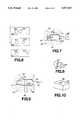
- FIGS. 1A and Bare vertical cross-sections of a first embodiment of the invention.
- FIG. 2is a vertical cross-section of a second embodiment of the invention in which an externally measured sample is added to the apparatus.
- FIG. 3is a vertical cross-section of a third embodiment of the invention.
- FIG. 4is a vertical cross-section of a fourth embodiment of the invention.
- FIG. 5is a vertical cross-section of a fifth embodiment of the invention.
- FIG. 6is a plan view of three diluent application site covers for use with the embodiment of FIG. 5.
- FIG. 7is an expanded vertical cross-sectional view of a valve and the surrounding parts of the apparatus of FIG. 1A.
- FIG. 8is a perspective view of the valve of FIG. 7.
- FIG. 9is an expanded vertical cross-sectional view of a second embodiment of a valve of the apparatus of FIG. 1A.
- FIG. 10is a perspective view of the valve of FIG. 9.
- FIG. 11is a perspective view of a sixth embodiment of the invention.
- FIGS. 12A and Bare vertical cross-sections of a seventh embodiment of the invention.
- FIG. 13is a schematic diagram of reagents and their location when using a device of FIGS. 12A and B to carry out an analysis of hemoglobin A1c.
- the present inventionprovides an apparatus and a method by which small samples can easily be measured and diluted.
- the apparatusis small, convenient to use, and requires no moving parts for the movement of fluid, gravity and capillary action being sufficient to provide all motive forces.
- Valvesare provided to control the movement of fluid from chamber to chamber.
- the valvesare integrated into the apparatus in most cases and, in preferred embodiments, are controlled by a simple push/release mechanism that can be controlled by an external solenoid.
- valvescan consist of externally controlled vent covers to control the flow of liquids in capillary spaces.
- the apparatusreferred to herein as a dilution and mixing cartridge, is easy to use, is inexpensive to manufacture, and can be used in a large number of procedures in which a dilution or a series of dilutions of a small sample is required.
- the parts of the cartridgeinclude a sample application site, a mixing chamber, a diluent application site, a mixture isolating and measuring chamber, and at least one valve controlling passage of fluid from the mixing chamber to the mixture isolating and measuring chamber.
- a second valve controlling passage of fluid from the diluent application site to the mixing chambercan be present as part of the cartridge or can be present as part of an apparatus into which the cartridge fits which operates a vent in the cartridge to control flow of a liquid in a capillary pathway.
- a sample measuring chamberwill also be present.
- valvesfor controlling passage of fluid between internal chambers of the device. These valves allow multiple use of the same chambers (e.g., serial dilutions a single mixing chamber) in contrast to the linear flow arrangement present in the previously described apparatus.
- the sampleis a liquid and may be derived from any source, such as a physiological fluid; e.g., blood, saliva, occular lens fluid, cerebral spinal fluid, pus, sweat, exudate, urine, milk, or the like.
- the liquid samplemay be subjected to prior treatment, such as preparing serum or plasma from blood or dissolving or suspending a solid in a liquid.
- sample treatments prior to application to the apparatus of the inventioninclude concentration, filtration, distillation, dialysis, inactivation of natural components, chromatography, and addition of reagents.
- other liquid samplescan be employed. Examples of other liquid samples include process streams, water, plant fluids, chemical reaction media, biological growth media, and the like.
- the liquidwill be aqueous, although other liquids can be employed.
- Aqueous mediamay contain additional miscible liquids, particularly oxygenated organic solvents, such as lower alkanols, dimethyl formamide, dimethyl sulfoxide, acetone, and the like.
- oxygenated organic solventssuch as lower alkanols, dimethyl formamide, dimethyl sulfoxide, acetone, and the like.
- the solventswill be present in less than about 40 vol %, more usually in less than about 20 vol %, in order to maintain the high surface tension that is present in aqueous solutions.
- the apparatus of the inventioncan be modified as described below for use with liquids exhibiting different surface tensions.
- the sample application sitewill generally be a cavity on a surface of the apparatus or may simply be an opening (optionally surrounded by a ring or tube) leading to the interior of the apparatus.
- the sample application sitecan contain a filter, for example, to separate red blood cells from plasma (see U.S. application Ser. No. 924,633, filed Oct. 29, 1986), or may represent a connection between the apparatus of the invention and some other apparatus that manipulates the sample prior to its entering the present dilution apparatus.
- the application sitecan be a recess into which a standard capillary tube will fit.
- the capillary tubecan act either as a convenient means for transferring the sample or can act as a measuring chamber, either by completely filling the capillary or by filling the capillary to a particular mark.
- the sample application sitein such embodiments acts as a point of transfer.
- the sample application sitewill be a measuring chamber, such as a recess on an upper surface of the device into which sample is inserted.
- the application sitecan be provided with a raised lip surrounded by a catch basin so that the application site can be filled to overflowing, with excess sample overflowing into the catch basin. A defined volume of sample can therefore be readily obtained.
- the sample application sitecan be a chamber having two channels leading away from the chamber.
- the first channelis or leads to an internal sample measuring chamber as described herein.
- the second channelis a drain that leads to an excess sample chamber.
- the excess sample channelis smaller than the measuring channel or is otherwise provided with means to restrict flow through the excess sample channel so that sample applied to the sample application site will flow primarily into the measuring chamber until the measuring chamber is filled, after which excess sample is drained away by the excess sample channel.
- the liquid sampleflows without the application of external force (except unassisted gravity) into the sample measuring chamber, which has a fixed volume.
- a capillary channel or non-capillary channel capable of transporting fluidcan connect the sample application site to the measuring chamber, or the capillary or other channel exiting the sample application site can itself be the measuring chamber.
- the measuring chambercan be a capillary channel or chamber, in which case capillary action will aid or in some cases provide all the force necessary for filling the measuring chamber with sample from the sample application site.
- Capillary channels and chamberswill generally have at least one dimension perpendicular to the flowpath in the range 0.01 to 2.0 mm, more generally 0.1 to 1.0 mm. However, larger measuring chambers are also possible.
- the sample measuring chamberis said to be in "fluid receiving relationship" to the sample application site in order to indicate that unassisted flow occurs.
- the geometry of the measuring chamberis such that when diluent is added to the apparatus at a later step, essentially all of the sample in the measuring chamber will be expelled or drawn into the mixing chamber.
- One means of accomplishing thisis by providing for smooth flow of diluent through the measuring chamber.
- a straight tube open at both endsis thus a preferred embodiment for this type of measuring chamber.
- diluententers the measuring chamber in a front across the entire cross-sectional area of flow. This helps avoid mixing of diluent with sample and passage of diluent through the measuring chamber without expelling essentially all of the sample, which can occur if a small stream of diluent enters into a broader cross-sectional area of the measuring chamber.
- the sample measuring chambercan terminate at a junction leading into a passageway between the diluent application site and the mixing chamber, both of which are later described. Passage of moving diluent past the junction will serve to draw sample into the mixing chamber.
- the passagewaycan be narrowed at the location of the junction to assist in drawing sample into the passageway and thus into the mixing chamber. This embodiment is particularly useful when the sample measuring chamber is a simple tube connecting the sample application site to the passageway between the diluent application site and the mixing chamber.
- stop flow junctionWhen sample flows into an internal fixed volume measuring chamber, flow generally stops when sample reaches a stop flow junction, so called because it marks the junction between the early part of the fluid track in which sample flows freely and the later part of the fluid track into which sample does not normally flow until the user initiates the dilution process. Since the stop flow junction exists at the limit of the flowpath of the sample, it will be found at one end of the measuring chamber. In some cases, this same location will be the beginning of the mixing chamber (i.e., when the two chambers are directly connected). However, in other cases an additional channel may connect the stop flow junction to the mixing chamber.
- flow stopcan occur both stably and metastably.
- a metastable flow stopis one in which flow stops on the macroscopic level but may resume without apparent cause after a time interval of a few seconds to a few minutes. Gradual creep of liquids along container walls or through microscopic or submicroscopic channels resulting from imperfections in the manufacturing process is believed to be the mechanism by which flow starts again once it has stopped. Additionally, small, undetectable vibrations (such as might be caused by persons walking near the apparatus or starting and stopping of nearby equipment, such as air-conditioning units) may also be sufficient to start flow in a metastable situation.
- any flow stopwhich can be sustained for at least 10 seconds, preferably at least one minute, and more preferably at least five minutes, is sufficient for the purposes of this invention.
- a stop flow junctionis not a traditional valve as it has no moving parts. Rather, this junction relies on backpressure from the surface tension of the liquid sample to stop flow.
- This backpressurecan be created in a number of ways. For example, backpressure is created when the cross-sectional area of the flowpath increases in a region in which there is contact between the liquid and the container walls (e.g., when a small tube enters a larger chamber or when the cross-sectional area of a channel increases). Greater backpressure and more consistent operation is achieved when the increase in cross-sectional area of the flowpath is abrupt rather than gradual, particularly when there is a break in capillarity in the sample flowpath.
- Imperfections in the container walls during gradual widening of chambersmay cause liquid to "creep" more on one side than another, thereby avoiding the creation of backpressure. Liquid can also creep around corners when imperfections are present. Unbalanced forces will also be present when the junction is not horizontal.
- a horizontal junctionfor example, occurs when a vertical tube enters the top horizontal surface of a chamber. If a horizontal tube enters a vertical wall of a container, a vertical junction is present, and the pressure at the bottom of the stop flow junction will be greater than the pressure at the top of the junction, due to hydrostatic pressure caused by the different heights of liquid. Nonetheless, non-horizontal stop flow junctions can be created by reducing the diameter of the smaller channel containing liquid as it enters the larger area, thereby reducing the difference in pressure between the upper and lower portions of the junction.
- the junctionwill be formed when a small-diameter measuring tube (i.e., measuring chamber) enters a larger receiving chamber.
- a small measuring chambercan enter the larger receiving chamber at a right angle or at an angle other than a right angle.
- the angle between the internal wall of the small tube and the surface of the chamber in the latter casewill be different at different locations around the circumference of the junction.
- the junctionbe as sharp as possible from a macroscopic view point, approaching as closely as possible the ideal junction formed by the intersection of the plane (which can be curved) forming the walls of the measuring chamber with the plane forming the wall of the receiving chamber surface in which the stop flow junction is found.
- the backpressurewill be controlled by the smallest radius of curvature assumed by the meniscus.
- Backpressureis also created when the surface that the liquid contacts changes to decrease adhesion between the liquid and the container wall (for example, when an aqueous sample moves from a hydrophilic to a hydrophobic surface).
- the surface properties of the various interior surfaces of the device of the inventioncan and generally will be controlled by various physical and/or chemical treatments. For a discussion of controlling surface properties of similar devices, see commonly assigned U.S. application Ser. No. 880,793, filed July 1, 1986.
- plastic surfacescan be treated to increase their hydrophilicity. Either the whole apparatus or specific parts can be treated. Alternatively, different parts of the apparatus can be made of different plastics. For capillary flow, contact angles of 0°-90° are sufficient, preferably 10°-85° and most preferably 30°-60°.
- the capillary surfaceswill be hydrophilic.
- a hydrophobic surfacewould be appropriate.
- valveto control flow of sample from the sample measuring chamber to the mixing chamber.
- Measuring/application sites for samplecan be provided as described later for diluent, and the exit of liquid from such application/measuring sites can be controlled by valves in the same manner.
- the sample application site, diluent application site, sample measuring chamber, and mixing chambercan be as described in U.S. application Ser. No. 90,026, described above.
- the apparatus of the present inventionwill differ in that valves are present, for example controlling exit of waste fluid from the mixing chamber or entry of a portion of the mixed sample and diluent to a hydrostatically connected measuring chamber that samples and measures a portion of the mixture prepared in the mixing chamber.
- other valvescan be present in the apparatus of the present invention, such as a valve controlling flow of diluent from the diluent application site.
- the mixing chambercan be used to determine the volume of diluent by providing a mixing chamber smaller than the diluent application site.
- volume of diluentis determined by the volume of the diluent application site, in which case the mixing chamber has a volume at least as great as and usually larger than the combined volume of sample and diluent.
- the geometry of the mixing chamberthere are no particular restraints on the geometry of the mixing chamber other than that smooth fluid flow be provided for in order to prevent trapping of gas bubbles.
- the ventis preferably in the non-wetted upper portion of the mixing chamber.
- the ventcan merely be a small hole terminated by a stop flow junction in order to avoid exit of liquid from the device or can be a more sophisticated vent designed for gas exit without exit of liquid (e.g., a microporous, hydrophobic plug capable of passing air but not hydrophilic liquids).
- a vent or other means to allow exit of trapped airmust be provided at every location in which the trapping of air would interfere with the passage of liquids between the various chambers and/or channels of the device.
- the method and apparatusare particularly suitable for measuring and diluting small quantities of liquids.
- the sample measuring chamberwill generally have a volume of from 0.1 ⁇ L to 100 ⁇ L, preferably 1 ⁇ L to 30 ⁇ L, and most preferably 3 ⁇ L to 10 ⁇ L.
- the diluent application site or mixing chamber(whichever acts to limit diluent volume) generally has a volume of from 3 ⁇ L to 1000 ⁇ L, preferably 10 ⁇ L to 300 ⁇ L, and most preferably 30 ⁇ L to 100 ⁇ L, thereby providing dilution ratios of from 10 4 :1 to 3:1, preferably 10 3 :1 to 10:1, and most preferably 100:1 to 10:1.
- Channels through which capillary flow will take placewill usually have opposing walls spaced in the range of about 0.01 mm to 2 mm, more usually about 0.1 mm to 1 mm.
- the capillary spacescan be tubular (which does not necessarily imply a circular cross-section but can be square or other regular shapes) or can represent the space formed by flat plates and side walls with the side walls being spaced further apart than a capillary distance.
- a tubular chamber with at least one flat sidee.g., a square cross-sectional area, a rectangle with adjacent sides differing in length by no more than a factor of 1:2 to 1:4, or a semicircular chamber
- channelsare being formed by the joining of two adjacent surfaces, one of which can be flat.
- Serial dilution and mixing capabilitiesare provided by a mixture measuring and isolating chamber hydrostatically connected to the mixing chamber, and a valve controlling passage of fluids from the mixing chamber to the mixture isolating chamber.
- the first dilutiontakes place as indicated above during which time the indicated valve is closed to prevent escape of liquid from the mixing chamber.
- the valve controlling flow to the mixture measuring chamberis opened and fluid flows from the mixing chamber under the influence of hydrostatic pressure and/or capillary attraction.
- the portion of the mixture isolating chamber into which the mixture flowsis smaller in volume than the total volume of mixed sample and diluent. This volume is determined by the geometry of the chamber, the amount of hydrostatic pressure available from liquid in the mixing chamber, and any capillary forces that are present.
- the mixture isolating chambercan be a tube (which does not imply circular cross-section), at least a portion of which extends upwardly from the connecting point between the mixing chamber and the mixture measuring chamber.
- the valveWhen the valve is open, the mixture flows into the mixture isolating chamber until the level of liquids in the two chambers becomes equal, thereby equalizing hydrostatic pressure (assuming that capillary action is negligible).
- the remainder of the mixturecan be drained from the mixing chamber by opening a second valve that leads to a waste fluid exit in the mixing chamber. After the second valve is closed, opening the first valve allows the isolated portion of the mixture to return to the mixing chamber. A second dilution can then take place in the mixing chamber.
- a portion of the mixture measuring chambercan extend below the first valve, for example in a V or U shape, with another portion extending upward.
- Providing a third valve at the low point of the mixture measuring chamberallows the measured portion of the first mixture to be drained into a second mixing chamber. In this embodiment, there is no requirement for the waste fluid exit in the mixing chamber since there is no need to remove the remainder of the first diluted mixture from the first mixing chamber.
- the diameter of the measuring chambercan be of capillary dimensions so that capillary force is significant in determining the level to which mixture rises in the mixture measuring chamber.
- This heightcan readily be regulated by providing a vent or large diameter segment (such as a bubble chamber) to break capillarity.
- the apparatus of the inventioncan be designed for use with a particular assay or can be designed and prepared as an apparatus in which multiple assays can be carried out, depending on the order in which various valves are opened and closed and the contents of the various diluents, which can contain reagents for the development of a detectable signal (e.g., a color reaction) that depends on the presence of an analyte in the sample.
- a detectable signale.g., a color reaction
- valvesthat will control the passage of liquids between chambers and/or channels can be used in the apparatus of the present invention.
- Simple valvesthat can be actuated to move between an open and a closed position by the application and release of a simple external force are preferred.
- valvesinclude resilient blocking members that are present in or adjacent to a liquid flowpath.
- a resilient blocking membercan be present in a converging or diverging pathway so that the narrow portion of the pathway is blocked by the resilient blocking member when the blocking member is in its normal position.
- Application of force in a direction generally away from the restricted portion of the flowpath and toward the wider portion of the flowpathwill open the valve by moving the blocking member away from the narrow walls of the flowpath.
- a normally open valvecan be provided which is blocked by movement of a resilient blocking member to a location that cuts off flow of liquid. Specific examples of such valves are set forth in more detail below.
- valvesinclude sliding pins closely engaging a channel that laterally traverses a fluid flowpath.
- the pinhas a segment capable of obstructing flow through the flowpath when the pin is in a first position and a segment capable of allowing flow through the flowpath when the pin is in a second position.
- Examples of such pinsinclude rectangular pins having a flowpath channel between two opposite faces of the pin, the flowpath channel being out of register when the block is in a closed position and in register with the principal flowpath when the block valve is open.
- Pins with circular cross-sectionscan be used by providing an obstructing segment of the pin that snugly engages the channel in which the pin fits and obstructs the flowpath when the pin is in a closed position.
- a smaller cross-sectional area(such as is present in the handle of a dumbbell) provides an annular flowpath around the smaller, central portion of the pin when the pin valve is in the open position.
- a resilient membercan be provided to bias the pin into either the closed or the open position. A force acting on the pin can then slide the pin to a second location so that the pin valve is in the alternate position.
- access for the application of an external force on the pinis provided so that the pin can be moved between its two positions.
- a section of the pin that protrudes externally from the apparatuscan be provided so that a force acting parallel to the sliding axis of the pin can move the pin from its first biased position to a second position by acting against the direction of the biasing force.
- an aperture leading from a face of the pin opposite the biasing force to the external environmentcan be provided.
- Externally applied pressuresuch as from compressed air or a finger of an external apparatus that enters the aperture, can be used to slide the pin between its open and closed positions.
- a resilient sealcan be provided to prevent loss of liquid through the aperture while allowing force to be applied to the pin. Such seals can also be provided for the resilient blocking members described above.
- valves that can be used as integral parts of a cartridge of the present inventionare not limited to those specifically exemplified here. Rather, any valve can be used that can control the flow of liquids through small flowpaths, such as flexible walls of a flowpath that can be compressed to restrict flow of liquid through the flowpath. Additionally, a dissolvable barrier can be provided in instances where an initially closed valve will be opened once and then maintained in the open position.
- a flowpath through which capillary flow occurscan be blocked by closing an external vent.
- the external ventWhen the external vent is closed, liquid cannot enter the capillary pathway because of air or other gases in the capillary pathway. Opening the vent allows liquid to enter the capillary pathway. If the vent is closed while liquid is contained in the capillary pathway, the isolated liquid can later be used for other manipulations.
- Valvesconsisting of external vent controls can be used in any situation where flow occurs through a capillary pathway (so that trapped air is effective to control flow of liquids) and where no liquid is stored in the cartridge prior to use. In many cases it is desirable to store premeasured diluents (which can contain reagents) in the cartridge when the cartridge is delivered to an end user. Internal mechanical valves are preferred for such uses in order to prevent accidental leakage.
- a cartridge-like deviceBy providing valves that can be operated by a simple externally applied force, a cartridge-like device can be provided in which the valves are opened and closed in a predetermined manner by an analytical device into which the cartridge is inserted.
- This analytical devicecan contain various optical and/or other types of sensors for detecting the presence of liquids or analytes in various mixing and/or measuring chambers of the cartridge in addition to providing means for opening and closing the valves.
- Reagentscan be provided at various locations in a device of the invention. Incubation times can be controlled by either manual operation of valves or by a mechanically or electronically stored program in the device into which the cartridge is inserted.
- the programwould control the order and timing of opening and closing valves.
- the programmed devicewould contain solenoids or other means for providing force to open and/or close valves.
- a movable sealing padthat is capable of closing the vent will form part of the external programmed device into which the cartridge is inserted.
- FIG. 1Ais a vertical cross-section of a first embodiment of the invention in which line A--A shows the location of the cross-sectional view in FIG. 1B.
- Line A--A in FIG. 1Bwhich is also a vertical cross-section of the first embodiment, shows the location of the view shown in FIG. 1A.
- Sample application site 130is located in a side face of body member 190.
- Diluent application site 110is a cavity in an upper face of block 190.
- Valve 112prevents premature passage of diluent from diluent application site 110 through passageway 114 to mixing chamber 140.
- Sample measuring chamber 132connects sample application site 130 to fluid passageway 114.
- a stop flow junctionis present at the intersection of sample measuring chamber 132 and passage 114.
- Vent 146allows air in mixing chamber 140 to exit from the chamber when sample and diluent enter the chamber. Valves 142 and 144 prevent premature exit of mixture from mixing chamber 140. Valve 142 controls passage of liquid between mixing chamber 140 and isolating chamber 160, which is a narrow channel sloping upward from valve 142. Valve 144 allows excess mixture to pass from mixing chamber 140 through waste liquid channel 152 to waste liquid container 150, which is connected by vent 154 to the external environment. Vent 162 allows entry of liquid from mixing chamber 140 into isolating chamber 160 when vent 142 is open. Second diluent application site 120 is controlled by valve 122 which selectively prevents diluent from flowing through connecting channel 124 into isolating chamber 160 and through valve 142 back into mixing chamber 140.
- Body member 190is provided with a lip 102 around the perimeter of the body member to provide a space 100 that acts as a catch basin for excess diluent. Diluent is measured by filling diluent application sites 110 and/or 120 and allowing a small amount of diluent to overflow lip 108 or 118, respectively, and flow into lower catch basin space 100, thereby ensuring complete filling of the diluent application site (and therefore accurate measurement of diluent).
- An access channel 113is provided for application of external pressure to valve 112 and resulting movement of the valve between open and closed positions. Details of exemplary valves are set forth in later Figures.
- the apparatus of FIG. 1can be used in the following manner, among others.
- a liquid samplesuch as a drop of blood adhering to a finger after a finger stick, is touched to sample application site 130.
- a measured amountis drawn by capillary action into sample measuring chamber 132.
- Diluentis then added to diluent application site 110 until diluent overflows lip 108.
- Valve 112is then opened to allow the measured amount of diluent in diluent application site 110 to flow through passage 114 into mixing chamber 140.
- Valves 142 and 144are both closed during this first mixing. Air that would otherwise be trapped in mixing chamber 140 exits through vent 146. Mixing in chamber 140 can be facilitated by including within the chamber a mixing bar or by rocking the complete apparatus back and forth.
- Vent 142is then opened to allow a hydrostatically controlled portion of the mixture to enter mixture isolation chamber 160. Mixture will rise into chamber 160 until hydrostatic and capillary forces are balanced. Valve 142 is then closed, isolating a portion of the mixture in chamber 160. The remainder of the mixture in chamber 140 is then drained through exit channel 152 into waste chamber 150 by opening valve 144. Valve 144 is closed and valve 142 is opened to allow reentry of the isolated mixture into mixing chamber 140. Diluent is then added to second diluent application site 120 and valve 122 is opened to allow dilution of the isolated portion of the mixture with the second diluent. By providing chambers of appropriate sizes, further dilution operations can be carried out by re-isolating a portion of the mixture in chamber 160 followed by addition of a third or further diluent.
- Apparatuses of the inventioncan readily be made by forming all cavities and passageways in body member 190 as shown in FIG. 1B.
- a cover plate 195is then used to form the internal cavities, with any access channels (such as access channel 113 shown for valve 112) or vents being provided in the cover panel as desired.
- FIG. 2shows a second embodiment of the invention in which a separate capillary tube 232 is provided for obtaining and/or measuring a sample.
- Sample application site 230 in this embodimentis a recess into which capillary tube 232 fits.
- Connecting channel 234allows sample to pass into passageway 214.
- Many of the features in this embodimentare strictly analogous to the features of the embodiment shown in FIG. 1. Such features are identified by a reference number in which the last two digits of the reference number are identical to the last two digits of the reference number in FIG. 1. The first digit of the reference number identifies the particular Figure.
- valve 212 in FIG. 2is identical in function to valve 112 in FIG. 1. Accordingly, the remainder of the description of this and other Figures will be principally directed to the differences between embodiments.
- Mixing chamber 240 of FIG. 2differs from the mixing chamber of the embodiment shown in FIG. 1 in that no waste liquid exit is provided. Instead, a single dilution takes place in chamber 240 after which valve 242 is opened. Mixture flows under hydrostatic control into descending arm 264 of the sample isolating chamber of this embodiment and then upward into ascending channel 266 and/or vertical channel 268. Valve 242 is then closed and a second mixing operation occurs in chamber 270. Valve 272 is opened to allow sample to flow into second mixing chamber 270 after which valve 222 is opened to allow diluent in diluent application 220 to enter chamber 270. Providing a three-part isolation chamber in the manner shown in FIG. 2 prevents inadvertent retention of the first mixture in channel 264, which would be likely to occur if channel 266 were not present. Channel 266 provides access for air from vent 262 so that channel 264 can freely drain into second mixing chamber 270.
- FIG. 3shows an embodiment in which serial dilutions can take place using a single diluent application site.
- Isolation chamber 360is connected to the external environment by vent 362 but is not itself connected to a second diluent application site.
- valve 342is sequentially opened and closed to isolate a hydrostatically determined portion of the first mixture in chamber 360.
- Valve 344is then opened to drain the remainder of the first mixture into waste liquid chamber 350, after which valve 344 is closed.
- Valve 342is then reopened to allow the isolated portion of the first mixture in chamber 360 to reenter chamber 340.
- valve 312At some time after the closing of valve 312, a second diluent (or a second volume of the first diluent) is added to diluent application site 310. Valve 312 is then reopened to allow formation of a second mixture in mixing chamber 340. This operation can be repeated as often as desired or until the capacity of waste chamber 350 is exhausted.
- FIG. 4shows an embodiment of the invention in which the sample application site and sample measuring site are the same. Passage of sample from the sample application/measuring site 430/432 is controlled by valve 431. Sample passes through passageway 433 to mixing chamber 440 where it mixes with diluent from diluent application site 410. After mixing, valve 442 is sequentially opened and closed to isolate a portion of the first mixture in chamber 460. A bubble chamber (non-capillary space) 461 is provided to prevent capillarity from drawing excess liquid into chamber 460. The remaining parts of this embodiment and its mode of operation are as described for FIG. 1.
- FIG. 5shows a complex embodiment of the invention in which multiple analyses can be carried out, depending on the combination of sample application sites, diluent application sites, and valving operations.
- Multiple sample measuring chambers 532, 532' and 532" of different volumesare provided to allow for the measurement of different sizes of samples.
- diluent application sites 520, 520' and 520" of different volumescan also be provided, each controlled respectively by valves 522, 522' and 522".
- Both a waste liquid chamber 550 and a second mixing chamber 570are provided so that mixing (and subsequent measurements) can take place in either mixing chamber. Alternate isolating chambers are provided under the control of different valving systems.
- valve 542can be opened while valve 543 remains closed.
- Channel 566therefore acts independently of channels 564 and 568 to isolate a portion of the first mixture.
- valve 542can remain closed while valves 543 and 563 are opened.
- channels 564 and 568act as the mixture isolating chamber.
- valves 543 and 563are opened to allow the trapped portion of the first mixture to drain into second mixing chamber 570.
- Channel 566is not needed in this sequence of steps, unlike the embodiment of FIG. 2, since draining chamber 540 allows vent 546 to supply air for the mixture trapped in channel 564.
- FIG. 5shows a sample application site cover 535, which can be, for example, tape applied to cover all but one of the sample application sites for a particular assay.
- cover 501allows access through channels 502 and 503 only to diluent application sites 510 and 520.
- alternate coverscan be provided for different analyses in which access channels are present in different locations to allow access to different diluent application sites.
- FIG. 7is a cross-sectional view of a valve such as might be present as valve 112 of the embodiment of FIG. 1.
- a channel 188is present in the apparatus, which here is formed from base member 190 and cover plate 195. This channel traverses a flowpath of sample from diluent application site 110 to passageway 114 (which leads to mixing chamber 140).
- the valve shown in cross-section in FIG. 7is shown in a perspective view in FIG. 8.
- the portion of the valve that slides in the channelconsists of a cylindrical pin with sections having different diameters.
- the pinis maintained in this position by a resilient member 180, such as a spring, which presses outward on the body of valve 112.
- the depth of channel 188 in cover plate 195is selected to retain pin 112 at the proper location.
- a projection 186is provided on the end of pin 112 in order that an externally applied force operating parallel to and against the force produced by resilient member 180, which biases the valve into the closed position, can slide pin 112 in channel 188 to an open position in which segment 184 moves into the flowpath of liquid.
- Section 184 of pin 112is of smaller diameter than segment 182 so that an annular flowpath of liquid is provided around the central portion of valve 112 at segment 184.
- an actuating member 196which is part of the apparatus into which the cartridge of the invention fits, can move in the direction shown by the arrow in FIG. 7 to act on protruding portion 186 of pin 112. When actuating member 196 contacts cover plate 195, thereby moving pin 112 to its maximum extent, valve 112 is in the maximum open position.
- FIGS. 9 and 10A second embodiment of a valve is shown in FIGS. 9 and 10 with FIG. 9 being a vertical cross-sectional view and FIG. 10 being a perspective view of the sliding pin.
- the pinis rectangular with a channel 185 between opposite faces to allow passage of liquid. A portion of the same face 187 obstructs passage of liquid when the pin moves to the closed position.
- the valve of FIG. 9differs from the valve of FIG. 7 in several ways.
- Pin 144is biased by a foam pad 181 to a normally open position rather than a normally closed position.
- Access channel 143is provided in cover plate 195, similar to access channel 113 of FIG. 7. However, no projection is provided on the face of pin 144. Instead, a pin 197 is provided as part of the analytical apparatus into which the cartridge fits.
- Pin 197is located so as to enter channel 143 when moved in the direction shown by the arrow in FIG. 9. This embodiment provides easily actuated valves but avoids projections on the outer surface of the cartridge which might accidently be triggered by handling.
- Channel 188has shoulders 183 which prevent excessive movement of pin 144.
- valve 144 of FIG. 9is equivalent to valve 144 of FIG. 1.
- the valves of FIGS. 7 and 9could be used at any location in the apparatus of the invention in which a valve is called for.
- many variations of valves of this typewill be apparent to those skilled in the art from the description of the specific valves.
- FIG. 11is a perspective drawing in scale of an apparatus of the invention that resembles the device shown schematically in FIGS. 1A and 1B.
- the last two digits of the reference numberscorrespond with the last two digits of the reference numbers in FIGS. 1A and 1B.
- Valves 612, 622, 642, and 644are of the type shown in FIGS. 7 and 8 except that projection 186 of the pin shown in FIG. 8 is not present. Instead, the pin is contacted internally as shown in FIG. 9.
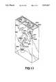
- FIG. 12Ais a vertical cross-section of a seventh embodiment of the invention in which line B--B shows the location of the cross-sectional view in FIG. 12B.
- Line A--A in FIG. 12Bwhich is also a vertical cross-section of the seventh embodiment, shows the location of the view shown in FIG. 12A.
- the device as shownis prepared from a base piece 790 and two cover plates 795 and 797. Most of the passageways and chambers are molded into base piece 790.
- Cover plate 795contains apertures, such as aperture 713, through which force can be applied to operate internal valves, such as valve 712.
- a resilient blocking member 712is present in a channel 788 that diverges in the direction of the flowpath.
- resilient blocking member 712The narrow end of channel 788 is blocked by one end of resilient blocking member 712, which is held in the blocking position by internal compression forces exerted when cover plate 797 traps blocking member 712 in channel 788.
- a resilient seal 715is provided so that force can be applied through aperture 713 to blocking member 712 without leakage of sample or diluent from the device. Pressure on the end of resilient member 712 pushes it away from the narrow blocking portion of channel 788 toward the wider portion where flow can occur.
- resilient blocking member 712could be approximately the size and shape of a thin lead pencil eraser and could be made of silicon rubber.
- valve 712When valve 712 is open, diluent flows from chamber 710 through channel 711 along the front face of block 790 and then through 788 containing resilient blocking member (valve) 712. The flowpath continues into fluid passageway 714 at the rear of block 790 where liquid enters a channel traversing block 790 and then continuing across the front face of block 790 until liquid enters mixing chamber 740.
- Access panel 745is provided to chamber 740 so that reagents can be added to the chamber during the manufacturing process, if desired.
- Sample application site 730is provided in an upper face of block 790. Two channels lead away from the sample application site. One channel is measuring chamber 732, which operates as described above for similar measuring chambers. An additional channel (734) is provided to remove excess sample from sample application site 730. Channel 734 is smaller than channel 732 so that sample initially flows preferentially into measuring channel 732. Excess sample channel 734 then leads excess sample into excess sample chamber 736, which is vented through vent 738 to the atmosphere. A measured volume of sample is therefore contained in channel 732 regardless of the amount of sample applied to application site 730.
- Recess 747is provided in a lower surface of block 790 immediately below chamber 740 in which mixing occurs. This recess allows close approach of a magnet or other means to activate a stirring bar or plate retained in chamber 740 while still allowing waste liquid chamber 750 to be located below (although displaced from) mixing chamber 740 in order that excess mixture an be readily drained into chamber 750.
- a capillary pathwayis provided for isolating a portion of the mixture initially formed in mixing chamber 740.
- Channel 761 along the front face of block 790leads to a capillary space 762 to which a reagent can be applied before placing cover plate 795 over base 790.
- the capillary pathproceeds to aperture 763, which traverses block 790.
- Capillary path 764continues on the back face of block 790 and terminates at vent space 765 through back plate 795. Actual venting takes place through aperture 767 in back cover plate 797.
- a solenoid-controlled vent seal(not shown) forms part of the apparatus in which this embodiment is placed for controlling entry and exit of liquids into this capillary pathway.
- the vent sealis then replaced, isolating a predetermined volume of mixture in the space formed by the entire capillary track (761-764). Liquid does not enter channel 724 because of air trapped in this space.
- the vent seal(valve) is reopened to allow the isolated mixture to reenter mixing chamber 740.
- Diluent in chamber 720further aids to expel trapped liquid in channel 761 and chamber 762 and to draw in trapped liquid from channels 763 nd 764 when valve 722 is opened.
- Diluent chambers 710 and 720are provided with a removable, sealable cover 705 that traps premeasured diluent in these chambers. Cover 705 is removed prior to use in order that flow can occur when valves 712 and 722 are opened. Optional catch spaces 701 and 721 are provided so that chamber 710 and/or 720 can be refilled with diluent, if desired.
- FIG. 13is a schematic diagram showing reagents that would be used with a cartridge of the type as shown in FIG. 12 to carry out a specific diagnosis.
- Hemoglobin A1ca minor hemoglobin component
- Hemoglobin A1c measurementtherefore provides an assessment of long-term insulin control in diabetics.
- An analysisrequires an initial mixing of whole blood with a first set of reagents to determine total hemoglobin content followed by determination of hemoglobin A1c content on an aliquot of the first mixture. The process steps are shown schematically in FIG. 13. A sample from an unmeasured blood drop will be drawn into a sample capillary spontaneously.
- the sample sizeis defined by the volume of the sample capillary since flow of blood stops at the junction of the sample capillary and the pathway leading from the denaturant reservoir to the mixing/ reading chamber.
- valve AWhen valve A is open, thiocyanate solution will flow toward the mixing chamber, drawing the blood sample with it. The mixture of blood and thiocyanate will fill the mixing chamber, but liquid flow will stop when the mixture reaches an air vent (not shown in FIG. 13). Homogeneous mixing of blood and thiocyanate will now occur, driven by a reciprocating mixing plate, and the ferricyanide and agglutinator reagents present in the mixing chamber will dissolve. After about 1 minute, the blood will be lysed and the hemoglobin denatured.
- valve Awill then be closed and the vent uncovered to allow a portion of the mixture to flow into the measurement (mixture isolation) capillary.
- the ventis then closed to prevent the isolated mixture from draining from the mixing chamber during the next step, in which valve B is opened so that all the remaining contents of the reaction chamber drain into the overflow chamber.
- valve Bwill be closed and valve C and the vent opened, allowing diluent to flow through the dry antibody-latex reagent chamber, resuspending the reagent, and displacing the sample of denatured blood (i.e., the isolated mixture) from the measurement capillary into the mixing/reaction chamber.
- the denatured blood/reagent mixturewill then be mixed and assayed for hemoglobin A1c by measurement of the change in turbidity over about 30 seconds. Turbidity increases as a result of agglutination of antibody-coated latex particles, the antibody being specific for hemoglobin A1c.
- the location of reagents described in FIG. 13 in the apparatus shown in FIGS. 12A and Bis readily apparent.
- the sample capillary of FIG. 13is measuring chamber 732 of FIG. 12B.
- Thiocyanate solutionis present in chamber 710, A1c assay diluent in chamber 720, dry antibody-latex particles in chamber 762, and ferricyanide and agglutinator at different locations in chamber 740.
- Capillary channels 761-764provide the measurement (mixture isolation) capillary with vent control occurring at vent chamber 765.
- Valves A, B, and C of FIG. 13are respectively valves 712, 744, and 722 of FIG. 12B.
- the entire apparatus shown in FIGS. 12A and Bwould be approximately 2 inches high and less than 3 inches wide with body member 790 being 0.394 inch (1.00 cm) in thickness to provide a standard path length for spectrophotometric analysis of samples in chamber 740.
Landscapes
- Chemical & Material Sciences (AREA)
- Chemical Kinetics & Catalysis (AREA)
- General Health & Medical Sciences (AREA)
- Life Sciences & Earth Sciences (AREA)
- Analytical Chemistry (AREA)
- Biochemistry (AREA)
- Physics & Mathematics (AREA)
- General Physics & Mathematics (AREA)
- Immunology (AREA)
- Pathology (AREA)
- Health & Medical Sciences (AREA)
- Automatic Analysis And Handling Materials Therefor (AREA)
- Sampling And Sample Adjustment (AREA)
Abstract
Description
Claims (20)
Priority Applications (8)
| Application Number | Priority Date | Filing Date | Title |
|---|---|---|---|
| US07/117,791US5077017A (en) | 1987-11-05 | 1987-11-05 | Integrated serial dilution and mixing cartridge |
| ES88307946TES2049254T3 (en) | 1987-08-27 | 1988-08-26 | APPARATUS AND PROCEDURE FOR THE DILUTION AND MIXING OF LIQUID SAMPLES. |
| AT88307946TATE98372T1 (en) | 1987-08-27 | 1988-08-26 | APPARATUS AND METHOD FOR DILUTING AND MIXING LIQUID SAMPLES. |
| EP88307946AEP0305210B1 (en) | 1987-08-27 | 1988-08-26 | Apparatus and method for dilution and mixing of liquid samples |
| CA000575875ACA1333850C (en) | 1987-08-27 | 1988-08-26 | Apparatus and method for dilution and mixing of liquid samples |
| DE3886140TDE3886140T2 (en) | 1987-08-27 | 1988-08-26 | Device and method for diluting and mixing liquid samples. |
| JP63213515AJPH0756492B2 (en) | 1987-08-27 | 1988-08-27 | Device and method for dilution and mixing of liquid samples |
| AU21639/88AAU615208B2 (en) | 1987-08-27 | 1988-08-29 | Apparatus and method for dilution and mixing of liquid samples |
Applications Claiming Priority (1)
| Application Number | Priority Date | Filing Date | Title |
|---|---|---|---|
| US07/117,791US5077017A (en) | 1987-11-05 | 1987-11-05 | Integrated serial dilution and mixing cartridge |
Publications (1)
| Publication Number | Publication Date |
|---|---|
| US5077017Atrue US5077017A (en) | 1991-12-31 |
Family
ID=22374848
Family Applications (1)
| Application Number | Title | Priority Date | Filing Date |
|---|---|---|---|
| US07/117,791Expired - LifetimeUS5077017A (en) | 1987-08-27 | 1987-11-05 | Integrated serial dilution and mixing cartridge |
Country Status (1)
| Country | Link |
|---|---|
| US (1) | US5077017A (en) |
Cited By (121)
| Publication number | Priority date | Publication date | Assignee | Title |
|---|---|---|---|---|
| US5222808A (en)* | 1992-04-10 | 1993-06-29 | Biotrack, Inc. | Capillary mixing device |
| US5223219A (en)* | 1992-04-10 | 1993-06-29 | Biotrack, Inc. | Analytical cartridge and system for detecting analytes in liquid samples |
| WO1996007919A1 (en)* | 1994-09-02 | 1996-03-14 | Biometric Imaging, Inc. | A disposable cartridge and method for an assay of a biological sample |
| DE29608616U1 (en)* | 1996-05-11 | 1996-08-01 | SBF Wasser und Umwelt Zweigniederlassung der Preussag Anlagenbau GmbH, 31228 Peine | Mixing vessel |
| US5723093A (en)* | 1994-07-19 | 1998-03-03 | Commissariat A L'energie Atomique | Apparatus for the continuous sampling and analysis of a liquid effluent |
| US5846396A (en)* | 1994-11-10 | 1998-12-08 | Sarnoff Corporation | Liquid distribution system |
| USD409758S (en)* | 1998-01-14 | 1999-05-11 | Accumetrics | Sample cartridge |
| US5980704A (en)* | 1995-06-07 | 1999-11-09 | David Sarnoff Research Center Inc. | Method and system for inhibiting cross-contamination in fluids of combinatorial chemistry device |
| US6016712A (en)* | 1997-09-18 | 2000-01-25 | Accumetrics | Device for receiving and processing a sample |
| US6117396A (en)* | 1998-02-18 | 2000-09-12 | Orchid Biocomputer, Inc. | Device for delivering defined volumes |
| US6284548B1 (en)* | 1998-02-06 | 2001-09-04 | Boule Medical Ab | Blood testing method and apparatus |
| US6296020B1 (en) | 1998-10-13 | 2001-10-02 | Biomicro Systems, Inc. | Fluid circuit components based upon passive fluid dynamics |
| US6403037B1 (en)* | 2000-02-04 | 2002-06-11 | Cepheid | Reaction vessel and temperature control system |
| US6485690B1 (en) | 1999-05-27 | 2002-11-26 | Orchid Biosciences, Inc. | Multiple fluid sample processor and system |
| US20020187074A1 (en)* | 2001-06-07 | 2002-12-12 | Nanostream, Inc. | Microfluidic analytical devices and methods |
| US20020187560A1 (en)* | 2001-06-07 | 2002-12-12 | Nanostream, Inc. | Microfluidic systems and methods for combining discrete fluid volumes |
| US20030017083A1 (en)* | 2001-07-17 | 2003-01-23 | Cybio Instrument Gmbh | Positioning aid for liquid handling devices |
| US6565815B1 (en)* | 1997-02-28 | 2003-05-20 | Cepheid | Heat exchanging, optically interrogated chemical reaction assembly |
| US6591852B1 (en) | 1998-10-13 | 2003-07-15 | Biomicro Systems, Inc. | Fluid circuit components based upon passive fluid dynamics |
| US6601613B2 (en) | 1998-10-13 | 2003-08-05 | Biomicro Systems, Inc. | Fluid circuit components based upon passive fluid dynamics |
| US20030153844A1 (en)* | 2001-12-04 | 2003-08-14 | Dave Smith | Integral sample collection tip |
| US20030152492A1 (en)* | 2000-07-25 | 2003-08-14 | Cepheid | Apparatus and reaction vessel for controlling the temperature of a sample |
| US20030198576A1 (en)* | 2002-02-22 | 2003-10-23 | Nanostream, Inc. | Ratiometric dilution devices and methods |
| US6637463B1 (en) | 1998-10-13 | 2003-10-28 | Biomicro Systems, Inc. | Multi-channel microfluidic system design with balanced fluid flow distribution |
| US20040213699A1 (en)* | 2001-11-21 | 2004-10-28 | Ingemar Berndtsson | Disposable apparatus for use in blood testing |
| US6858185B1 (en)* | 1999-08-25 | 2005-02-22 | Caliper Life Sciences, Inc. | Dilutions in high throughput systems with a single vacuum source |
| US20050214928A1 (en)* | 2002-06-11 | 2005-09-29 | Larsen Ulrik D | Disposable cartridge for characterizing particles suspended in a liquid |
| US7150995B2 (en) | 2004-01-16 | 2006-12-19 | Metrika, Inc. | Methods and systems for point of care bodily fluid analysis |
| US20070053796A1 (en)* | 2005-09-02 | 2007-03-08 | Jen-Jr Gau | Cartridge having variable volume reservoirs |
| US20080202217A1 (en)* | 2005-02-10 | 2008-08-28 | Chempaq A/S | Dual Sample Cartridge and Method for Characterizing Particles in Liquid |
| US20080223721A1 (en)* | 2007-01-19 | 2008-09-18 | Fluidigm Corporation | High Efficiency and High Precision Microfluidic Devices and Methods |
| USD582458S1 (en)* | 2007-03-19 | 2008-12-09 | Belanger, Inc. | Chemical mixing machine |
| US20090035865A1 (en)* | 2007-08-01 | 2009-02-05 | Demoor Colette Pamela | Moisture sensor |
| US20090123337A1 (en)* | 2005-06-24 | 2009-05-14 | Arkray,Inc | Cartridge |
| US20090166203A1 (en)* | 2007-12-28 | 2009-07-02 | General Electric Company | Injection method for microfluidic chips |
| WO2010027350A1 (en)* | 2008-09-02 | 2010-03-11 | Halliburton Energy Services Inc. | Acquiring and concentrating a selected portion of a sampled reservoir fluid |
| US20100101951A1 (en)* | 2008-10-27 | 2010-04-29 | General Electric Company | Electrophoresis system and method |
| US7875047B2 (en) | 2002-04-19 | 2011-01-25 | Pelikan Technologies, Inc. | Method and apparatus for a multi-use body fluid sampling device with sterility barrier release |
| US20110032513A1 (en)* | 2006-10-13 | 2011-02-10 | Mathieu Joanicot | Fluid flow device, assembly for determining at least one characteristic of a physico-chemical system therewith |
| US7892183B2 (en) | 2002-04-19 | 2011-02-22 | Pelikan Technologies, Inc. | Method and apparatus for body fluid sampling and analyte sensing |
| US7901365B2 (en) | 2002-04-19 | 2011-03-08 | Pelikan Technologies, Inc. | Method and apparatus for penetrating tissue |
| US7909775B2 (en) | 2001-06-12 | 2011-03-22 | Pelikan Technologies, Inc. | Method and apparatus for lancet launching device integrated onto a blood-sampling cartridge |
| US7909777B2 (en) | 2002-04-19 | 2011-03-22 | Pelikan Technologies, Inc | Method and apparatus for penetrating tissue |
| US7909778B2 (en) | 2002-04-19 | 2011-03-22 | Pelikan Technologies, Inc. | Method and apparatus for penetrating tissue |
| US7909774B2 (en) | 2002-04-19 | 2011-03-22 | Pelikan Technologies, Inc. | Method and apparatus for penetrating tissue |
| US7914465B2 (en) | 2002-04-19 | 2011-03-29 | Pelikan Technologies, Inc. | Method and apparatus for penetrating tissue |
| EP1803805A4 (en)* | 2004-08-05 | 2011-06-01 | Universal Bio Research Co Ltd | Reaction vessel, reaction vessel liquid introducing device, liquid introducing and reaction measuring device, and liquid introducing device |
| US20110126910A1 (en)* | 2009-07-23 | 2011-06-02 | Fluidigm Corporation | Microfluidic devices and methods for binary mixing |
| US7976476B2 (en) | 2002-04-19 | 2011-07-12 | Pelikan Technologies, Inc. | Device and method for variable speed lancet |
| US7981056B2 (en) | 2002-04-19 | 2011-07-19 | Pelikan Technologies, Inc. | Methods and apparatus for lancet actuation |
| US7981055B2 (en) | 2001-06-12 | 2011-07-19 | Pelikan Technologies, Inc. | Tissue penetration device |
| US7988645B2 (en) | 2001-06-12 | 2011-08-02 | Pelikan Technologies, Inc. | Self optimizing lancing device with adaptation means to temporal variations in cutaneous properties |
| US8007446B2 (en) | 2002-04-19 | 2011-08-30 | Pelikan Technologies, Inc. | Method and apparatus for penetrating tissue |
| US8062231B2 (en) | 2002-04-19 | 2011-11-22 | Pelikan Technologies, Inc. | Method and apparatus for penetrating tissue |
| US8079960B2 (en) | 2002-04-19 | 2011-12-20 | Pelikan Technologies, Inc. | Methods and apparatus for lancet actuation |
| US8118050B1 (en)* | 2007-02-02 | 2012-02-21 | Elemental Scientific Inc. | On-line constant flow dilution |
| CN101203763B (en)* | 2005-06-24 | 2012-04-25 | 爱科来株式会社 | Analysis module |
| US8197421B2 (en) | 2002-04-19 | 2012-06-12 | Pelikan Technologies, Inc. | Method and apparatus for penetrating tissue |
| US8221334B2 (en) | 2002-04-19 | 2012-07-17 | Sanofi-Aventis Deutschland Gmbh | Method and apparatus for penetrating tissue |
| US8251921B2 (en) | 2003-06-06 | 2012-08-28 | Sanofi-Aventis Deutschland Gmbh | Method and apparatus for body fluid sampling and analyte sensing |
| US8262614B2 (en) | 2003-05-30 | 2012-09-11 | Pelikan Technologies, Inc. | Method and apparatus for fluid injection |
| US8267870B2 (en) | 2002-04-19 | 2012-09-18 | Sanofi-Aventis Deutschland Gmbh | Method and apparatus for body fluid sampling with hybrid actuation |
| US8282576B2 (en) | 2003-09-29 | 2012-10-09 | Sanofi-Aventis Deutschland Gmbh | Method and apparatus for an improved sample capture device |
| US8296918B2 (en) | 2003-12-31 | 2012-10-30 | Sanofi-Aventis Deutschland Gmbh | Method of manufacturing a fluid sampling device with improved analyte detecting member configuration |
| US8333710B2 (en) | 2002-04-19 | 2012-12-18 | Sanofi-Aventis Deutschland Gmbh | Tissue penetration device |
| US8360992B2 (en) | 2002-04-19 | 2013-01-29 | Sanofi-Aventis Deutschland Gmbh | Method and apparatus for penetrating tissue |
| US8372016B2 (en) | 2002-04-19 | 2013-02-12 | Sanofi-Aventis Deutschland Gmbh | Method and apparatus for body fluid sampling and analyte sensing |
| US8382682B2 (en) | 2002-04-19 | 2013-02-26 | Sanofi-Aventis Deutschland Gmbh | Method and apparatus for penetrating tissue |
| US8435190B2 (en) | 2002-04-19 | 2013-05-07 | Sanofi-Aventis Deutschland Gmbh | Method and apparatus for penetrating tissue |
| US8439872B2 (en) | 1998-03-30 | 2013-05-14 | Sanofi-Aventis Deutschland Gmbh | Apparatus and method for penetration with shaft having a sensor for sensing penetration depth |
| US8556829B2 (en) | 2002-04-19 | 2013-10-15 | Sanofi-Aventis Deutschland Gmbh | Method and apparatus for penetrating tissue |
| US8574895B2 (en) | 2002-12-30 | 2013-11-05 | Sanofi-Aventis Deutschland Gmbh | Method and apparatus using optical techniques to measure analyte levels |
| US8573033B2 (en) | 2005-02-10 | 2013-11-05 | Koninklijke Philips N.V. | Method for characterizing particles in liquid using a dual sample cartridge |
| US20140000223A1 (en)* | 2010-11-10 | 2014-01-02 | Boehringer Ingelheim Microparts Gmbh | Method for filling a blister packaging with liquid, and blister packaging with a cavity for filling with liquid |
| US8641644B2 (en) | 2000-11-21 | 2014-02-04 | Sanofi-Aventis Deutschland Gmbh | Blood testing apparatus having a rotatable cartridge with multiple lancing elements and testing means |
| US8652831B2 (en) | 2004-12-30 | 2014-02-18 | Sanofi-Aventis Deutschland Gmbh | Method and apparatus for analyte measurement test time |
| US8668656B2 (en) | 2003-12-31 | 2014-03-11 | Sanofi-Aventis Deutschland Gmbh | Method and apparatus for improving fluidic flow and sample capture |
| US8685714B2 (en)* | 2000-07-14 | 2014-04-01 | Universal Biosensors Pty Ltd | Immunosensor |
| US8702624B2 (en) | 2006-09-29 | 2014-04-22 | Sanofi-Aventis Deutschland Gmbh | Analyte measurement device with a single shot actuator |
| US8721671B2 (en) | 2001-06-12 | 2014-05-13 | Sanofi-Aventis Deutschland Gmbh | Electric lancet actuator |
| US20140177378A1 (en)* | 2012-12-21 | 2014-06-26 | Intermolecular, Inc. | High Dilution Ratio by Successively Preparing and Diluting Chemicals |
| US8784335B2 (en) | 2002-04-19 | 2014-07-22 | Sanofi-Aventis Deutschland Gmbh | Body fluid sampling device with a capacitive sensor |
| US8828203B2 (en) | 2004-05-20 | 2014-09-09 | Sanofi-Aventis Deutschland Gmbh | Printable hydrogels for biosensors |
| US8857244B2 (en) | 2008-12-23 | 2014-10-14 | C A Casyso Ag | Cartridge device for a measuring system for measuring viscoelastic characteristics of a sample liquid, a corresponding measuring system, and a corresponding method |
| US8965476B2 (en) | 2010-04-16 | 2015-02-24 | Sanofi-Aventis Deutschland Gmbh | Tissue penetration device |
| US8961764B2 (en) | 2010-10-15 | 2015-02-24 | Lockheed Martin Corporation | Micro fluidic optic design |
| US9067207B2 (en) | 2009-06-04 | 2015-06-30 | University Of Virginia Patent Foundation | Optical approach for microfluidic DNA electrophoresis detection |
| US20150225803A1 (en)* | 2009-03-24 | 2015-08-13 | California Institute Of Technology | Multivolume devices, kits and related methods for quantification and detection of nucleic acids and other analytes |
| US9144401B2 (en) | 2003-06-11 | 2015-09-29 | Sanofi-Aventis Deutschland Gmbh | Low pain penetrating member |
| US20150343445A1 (en)* | 2012-12-21 | 2015-12-03 | Leica Biosystems Melbourne Pty Ltd | Method of producing a reagent on-board an instrument |
| US9226699B2 (en) | 2002-04-19 | 2016-01-05 | Sanofi-Aventis Deutschland Gmbh | Body fluid sampling module with a continuous compression tissue interface surface |
| US9248267B2 (en) | 2002-04-19 | 2016-02-02 | Sanofi-Aventis Deustchland Gmbh | Tissue penetration device |
| US9314194B2 (en) | 2002-04-19 | 2016-04-19 | Sanofi-Aventis Deutschland Gmbh | Tissue penetration device |
| US9322054B2 (en) | 2012-02-22 | 2016-04-26 | Lockheed Martin Corporation | Microfluidic cartridge |
| US20160121282A1 (en)* | 2011-01-28 | 2016-05-05 | Nichirei Biosciences Inc. | Means and method for stirring liquids in long thin containers |
| US9351680B2 (en) | 2003-10-14 | 2016-05-31 | Sanofi-Aventis Deutschland Gmbh | Method and apparatus for a variable user interface |
| US9375169B2 (en) | 2009-01-30 | 2016-06-28 | Sanofi-Aventis Deutschland Gmbh | Cam drive for managing disposable penetrating member actions with a single motor and motor and control system |
| US9386944B2 (en) | 2008-04-11 | 2016-07-12 | Sanofi-Aventis Deutschland Gmbh | Method and apparatus for analyte detecting device |
| US9427532B2 (en) | 2001-06-12 | 2016-08-30 | Sanofi-Aventis Deutschland Gmbh | Tissue penetration device |
| USD777343S1 (en) | 2015-05-28 | 2017-01-24 | C A Casyso Ag | Body fluid cartridge device |
| US9775553B2 (en) | 2004-06-03 | 2017-10-03 | Sanofi-Aventis Deutschland Gmbh | Method and apparatus for a fluid sampling device |
| US9795747B2 (en) | 2010-06-02 | 2017-10-24 | Sanofi-Aventis Deutschland Gmbh | Methods and apparatus for lancet actuation |
| US9820684B2 (en) | 2004-06-03 | 2017-11-21 | Sanofi-Aventis Deutschland Gmbh | Method and apparatus for a fluid sampling device |
| US9897618B2 (en) | 2014-09-29 | 2018-02-20 | C A Casyso Gmbh | Blood testing system |
| WO2018045114A1 (en)* | 2016-08-31 | 2018-03-08 | Ca Casyso Gmbh | Controlled blood delivery to mixing chamber of a blood testing cartridge |
| US20180304260A1 (en)* | 2017-04-21 | 2018-10-25 | Mesa Biotech, Inc. | Fluidic Test Cassette |
| US10175225B2 (en) | 2014-09-29 | 2019-01-08 | C A Casyso Ag | Blood testing system and method |
| US10288630B2 (en) | 2014-09-29 | 2019-05-14 | C A Casyso Gmbh | Blood testing system and method |
| US10295554B2 (en) | 2015-06-29 | 2019-05-21 | C A Casyso Gmbh | Blood testing system and method |
| EP3383473A4 (en)* | 2015-12-03 | 2019-06-26 | Ca Casyso Gmbh | SYSTEM AND METHOD FOR BLOOD TESTING |
| US10370705B2 (en) | 2009-03-24 | 2019-08-06 | University Of Chicago | Analysis devices, kits, and related methods for digital quantification of nucleic acids and other analytes |
| KR102038085B1 (en)* | 2018-08-06 | 2019-10-29 | 계명대학교 산학협력단 | A sample measurement strip sensor having magnetically coupled structure and sample mixing device for facilitating connected of strip sensor using the same |
| US10539579B2 (en) | 2014-09-29 | 2020-01-21 | C A Casyso Gmbh | Blood testing system and method |
| US10543485B2 (en) | 2009-03-24 | 2020-01-28 | University Of Chicago | Slip chip device and methods |
| US20200255792A1 (en)* | 2019-02-11 | 2020-08-13 | Lonza Ltd. | Buffer Formulation Method and System |
| US10816559B2 (en) | 2014-09-29 | 2020-10-27 | Ca Casyso Ag | Blood testing system and method |
| CN111868501A (en)* | 2018-02-27 | 2020-10-30 | 芯易诊有限公司 | Apparatus and method for sample analysis using serial dilution |
| US10843185B2 (en) | 2017-07-12 | 2020-11-24 | Ca Casyso Gmbh | Autoplatelet cartridge device |
| US12023672B2 (en) | 2015-04-24 | 2024-07-02 | Mesa Biotech, Inc. | Fluidic test cassette |
| CN118392615A (en)* | 2024-07-01 | 2024-07-26 | 上海皓信生物科技有限公司 | A novel reagent cup box and sample liquefaction dilution test method |
| US20240293820A1 (en)* | 2012-12-21 | 2024-09-05 | Leica Biosystems Melbourne Pty Ltd | Producing a reagent on-board an instrument |
Citations (13)
| Publication number | Priority date | Publication date | Assignee | Title |
|---|---|---|---|---|
| US1740004A (en)* | 1925-06-29 | 1929-12-17 | Libbey Owens Glass Co | Diaphragm valve |
| US2326487A (en)* | 1941-08-20 | 1943-08-10 | Glenn L Martin Co | Valve |
| US3073565A (en)* | 1960-12-23 | 1963-01-15 | Georges F A Daumy | Gate-valve |
| GB1163281A (en)* | 1965-09-02 | 1969-09-04 | Medicinsk Kemiska Lab Calab | Improvements in an Automatic Pipetting Device |
| US3799742A (en)* | 1971-12-20 | 1974-03-26 | C Coleman | Miniaturized integrated analytical test container |
| US3869068A (en)* | 1974-06-06 | 1975-03-04 | Hyperion Inc | Diluter probe assembly |
| EP0057110A2 (en)* | 1981-01-28 | 1982-08-04 | EASTMAN KODAK COMPANY (a New Jersey corporation) | Reaction vessel and method for combining liquids and reagents |
| US4503012A (en)* | 1983-04-19 | 1985-03-05 | American Monitor Corporation | Reagent dispensing system |
| US4610170A (en)* | 1983-11-30 | 1986-09-09 | Labsystems Oy | Method for the dilution of liquid samples |
| US4624928A (en)* | 1984-11-01 | 1986-11-25 | Allied Corporation | Liquid handling process |
| US4758409A (en)* | 1986-07-10 | 1988-07-19 | Techicon Instruments Corporation | Microsample cup |
| US4868129A (en)* | 1987-08-27 | 1989-09-19 | Biotrack Inc. | Apparatus and method for dilution and mixing of liquid samples |
| US4898832A (en)* | 1981-09-01 | 1990-02-06 | Boehringer Mannheim Gmbh | Process for carrying out analytical determinations and means for carrying out this process |
- 1987
- 1987-11-05USUS07/117,791patent/US5077017A/ennot_activeExpired - Lifetime
Patent Citations (13)
| Publication number | Priority date | Publication date | Assignee | Title |
|---|---|---|---|---|
| US1740004A (en)* | 1925-06-29 | 1929-12-17 | Libbey Owens Glass Co | Diaphragm valve |
| US2326487A (en)* | 1941-08-20 | 1943-08-10 | Glenn L Martin Co | Valve |
| US3073565A (en)* | 1960-12-23 | 1963-01-15 | Georges F A Daumy | Gate-valve |
| GB1163281A (en)* | 1965-09-02 | 1969-09-04 | Medicinsk Kemiska Lab Calab | Improvements in an Automatic Pipetting Device |
| US3799742A (en)* | 1971-12-20 | 1974-03-26 | C Coleman | Miniaturized integrated analytical test container |
| US3869068A (en)* | 1974-06-06 | 1975-03-04 | Hyperion Inc | Diluter probe assembly |
| EP0057110A2 (en)* | 1981-01-28 | 1982-08-04 | EASTMAN KODAK COMPANY (a New Jersey corporation) | Reaction vessel and method for combining liquids and reagents |
| US4898832A (en)* | 1981-09-01 | 1990-02-06 | Boehringer Mannheim Gmbh | Process for carrying out analytical determinations and means for carrying out this process |
| US4503012A (en)* | 1983-04-19 | 1985-03-05 | American Monitor Corporation | Reagent dispensing system |
| US4610170A (en)* | 1983-11-30 | 1986-09-09 | Labsystems Oy | Method for the dilution of liquid samples |
| US4624928A (en)* | 1984-11-01 | 1986-11-25 | Allied Corporation | Liquid handling process |
| US4758409A (en)* | 1986-07-10 | 1988-07-19 | Techicon Instruments Corporation | Microsample cup |
| US4868129A (en)* | 1987-08-27 | 1989-09-19 | Biotrack Inc. | Apparatus and method for dilution and mixing of liquid samples |
Cited By (262)
| Publication number | Priority date | Publication date | Assignee | Title |
|---|---|---|---|---|
| US5223219A (en)* | 1992-04-10 | 1993-06-29 | Biotrack, Inc. | Analytical cartridge and system for detecting analytes in liquid samples |
| WO1993020939A1 (en)* | 1992-04-10 | 1993-10-28 | Biotrack, Inc. | Analytical cartridge and system for detecting analytes |
| US5222808A (en)* | 1992-04-10 | 1993-06-29 | Biotrack, Inc. | Capillary mixing device |
| US5723093A (en)* | 1994-07-19 | 1998-03-03 | Commissariat A L'energie Atomique | Apparatus for the continuous sampling and analysis of a liquid effluent |
| WO1996007919A1 (en)* | 1994-09-02 | 1996-03-14 | Biometric Imaging, Inc. | A disposable cartridge and method for an assay of a biological sample |
| AU700750B2 (en)* | 1994-09-02 | 1999-01-14 | Biometric Imaging, Inc. | A disposable cartridge and method for an assay of a biological sample |
| US5912134A (en)* | 1994-09-02 | 1999-06-15 | Biometric Imaging, Inc. | Disposable cartridge and method for an assay of a biological sample |
| US5846396A (en)* | 1994-11-10 | 1998-12-08 | Sarnoff Corporation | Liquid distribution system |
| US6331439B1 (en) | 1995-06-07 | 2001-12-18 | Orchid Biosciences, Inc. | Device for selective distribution of liquids |
| US5980704A (en)* | 1995-06-07 | 1999-11-09 | David Sarnoff Research Center Inc. | Method and system for inhibiting cross-contamination in fluids of combinatorial chemistry device |
| DE29608616U1 (en)* | 1996-05-11 | 1996-08-01 | SBF Wasser und Umwelt Zweigniederlassung der Preussag Anlagenbau GmbH, 31228 Peine | Mixing vessel |
| US20080254532A1 (en)* | 1997-02-28 | 2008-10-16 | Cepheid | Thermal cycler with optical detector |
| US9316590B2 (en) | 1997-02-28 | 2016-04-19 | Cepheid | Apparatus for controlling and monitoring reactions |
| US6565815B1 (en)* | 1997-02-28 | 2003-05-20 | Cepheid | Heat exchanging, optically interrogated chemical reaction assembly |
| US8029733B2 (en) | 1997-02-28 | 2011-10-04 | Cepheid | Thermal cycler with optical detector |
| US6016712A (en)* | 1997-09-18 | 2000-01-25 | Accumetrics | Device for receiving and processing a sample |
| USD409758S (en)* | 1998-01-14 | 1999-05-11 | Accumetrics | Sample cartridge |
| US6284548B1 (en)* | 1998-02-06 | 2001-09-04 | Boule Medical Ab | Blood testing method and apparatus |
| US6117396A (en)* | 1998-02-18 | 2000-09-12 | Orchid Biocomputer, Inc. | Device for delivering defined volumes |
| US20030221771A1 (en)* | 1998-03-02 | 2003-12-04 | Cepheid | Method for fabricating a reaction vessel |
| US8293064B2 (en) | 1998-03-02 | 2012-10-23 | Cepheid | Method for fabricating a reaction vessel |
| US8439872B2 (en) | 1998-03-30 | 2013-05-14 | Sanofi-Aventis Deutschland Gmbh | Apparatus and method for penetration with shaft having a sensor for sensing penetration depth |
| US6637463B1 (en) | 1998-10-13 | 2003-10-28 | Biomicro Systems, Inc. | Multi-channel microfluidic system design with balanced fluid flow distribution |
| US6296020B1 (en) | 1998-10-13 | 2001-10-02 | Biomicro Systems, Inc. | Fluid circuit components based upon passive fluid dynamics |
| US6591852B1 (en) | 1998-10-13 | 2003-07-15 | Biomicro Systems, Inc. | Fluid circuit components based upon passive fluid dynamics |
| US6601613B2 (en) | 1998-10-13 | 2003-08-05 | Biomicro Systems, Inc. | Fluid circuit components based upon passive fluid dynamics |
| US6485690B1 (en) | 1999-05-27 | 2002-11-26 | Orchid Biosciences, Inc. | Multiple fluid sample processor and system |
| US6858185B1 (en)* | 1999-08-25 | 2005-02-22 | Caliper Life Sciences, Inc. | Dilutions in high throughput systems with a single vacuum source |
| US7101509B2 (en) | 2000-02-04 | 2006-09-05 | Cepheid | Reaction vessel and temperature control system |
| US20020168299A1 (en)* | 2000-02-04 | 2002-11-14 | Cepheid | Reaction vessel and temperature control system |
| US6403037B1 (en)* | 2000-02-04 | 2002-06-11 | Cepheid | Reaction vessel and temperature control system |
| US8685714B2 (en)* | 2000-07-14 | 2014-04-01 | Universal Biosensors Pty Ltd | Immunosensor |
| US20030152492A1 (en)* | 2000-07-25 | 2003-08-14 | Cepheid | Apparatus and reaction vessel for controlling the temperature of a sample |
| US7255833B2 (en) | 2000-07-25 | 2007-08-14 | Cepheid | Apparatus and reaction vessel for controlling the temperature of a sample |
| US8641644B2 (en) | 2000-11-21 | 2014-02-04 | Sanofi-Aventis Deutschland Gmbh | Blood testing apparatus having a rotatable cartridge with multiple lancing elements and testing means |
| US7318912B2 (en) | 2001-06-07 | 2008-01-15 | Nanostream, Inc. | Microfluidic systems and methods for combining discrete fluid volumes |
| US20020187560A1 (en)* | 2001-06-07 | 2002-12-12 | Nanostream, Inc. | Microfluidic systems and methods for combining discrete fluid volumes |
| US20020187074A1 (en)* | 2001-06-07 | 2002-12-12 | Nanostream, Inc. | Microfluidic analytical devices and methods |
| US6919046B2 (en) | 2001-06-07 | 2005-07-19 | Nanostream, Inc. | Microfluidic analytical devices and methods |
| US8679033B2 (en) | 2001-06-12 | 2014-03-25 | Sanofi-Aventis Deutschland Gmbh | Tissue penetration device |
| US9694144B2 (en) | 2001-06-12 | 2017-07-04 | Sanofi-Aventis Deutschland Gmbh | Sampling module device and method |
| US8360991B2 (en) | 2001-06-12 | 2013-01-29 | Sanofi-Aventis Deutschland Gmbh | Tissue penetration device |
| US8382683B2 (en) | 2001-06-12 | 2013-02-26 | Sanofi-Aventis Deutschland Gmbh | Tissue penetration device |
| US8337421B2 (en) | 2001-06-12 | 2012-12-25 | Sanofi-Aventis Deutschland Gmbh | Tissue penetration device |
| US7981055B2 (en) | 2001-06-12 | 2011-07-19 | Pelikan Technologies, Inc. | Tissue penetration device |
| US8622930B2 (en) | 2001-06-12 | 2014-01-07 | Sanofi-Aventis Deutschland Gmbh | Tissue penetration device |
| US8641643B2 (en) | 2001-06-12 | 2014-02-04 | Sanofi-Aventis Deutschland Gmbh | Sampling module device and method |
| US7909775B2 (en) | 2001-06-12 | 2011-03-22 | Pelikan Technologies, Inc. | Method and apparatus for lancet launching device integrated onto a blood-sampling cartridge |
| US8721671B2 (en) | 2001-06-12 | 2014-05-13 | Sanofi-Aventis Deutschland Gmbh | Electric lancet actuator |
| US8282577B2 (en) | 2001-06-12 | 2012-10-09 | Sanofi-Aventis Deutschland Gmbh | Method and apparatus for lancet launching device integrated onto a blood-sampling cartridge |
| US8216154B2 (en) | 2001-06-12 | 2012-07-10 | Sanofi-Aventis Deutschland Gmbh | Tissue penetration device |
| US8845550B2 (en) | 2001-06-12 | 2014-09-30 | Sanofi-Aventis Deutschland Gmbh | Tissue penetration device |
| US8211037B2 (en) | 2001-06-12 | 2012-07-03 | Pelikan Technologies, Inc. | Tissue penetration device |
| US8206317B2 (en) | 2001-06-12 | 2012-06-26 | Sanofi-Aventis Deutschland Gmbh | Tissue penetration device |
| US8343075B2 (en) | 2001-06-12 | 2013-01-01 | Sanofi-Aventis Deutschland Gmbh | Tissue penetration device |
| US7988645B2 (en) | 2001-06-12 | 2011-08-02 | Pelikan Technologies, Inc. | Self optimizing lancing device with adaptation means to temporal variations in cutaneous properties |
| US9937298B2 (en) | 2001-06-12 | 2018-04-10 | Sanofi-Aventis Deutschland Gmbh | Tissue penetration device |
| US8206319B2 (en) | 2001-06-12 | 2012-06-26 | Sanofi-Aventis Deutschland Gmbh | Tissue penetration device |
| US8162853B2 (en) | 2001-06-12 | 2012-04-24 | Pelikan Technologies, Inc. | Tissue penetration device |
| US9427532B2 (en) | 2001-06-12 | 2016-08-30 | Sanofi-Aventis Deutschland Gmbh | Tissue penetration device |
| US8123700B2 (en) | 2001-06-12 | 2012-02-28 | Pelikan Technologies, Inc. | Method and apparatus for lancet launching device integrated onto a blood-sampling cartridge |
| US9802007B2 (en) | 2001-06-12 | 2017-10-31 | Sanofi-Aventis Deutschland Gmbh | Methods and apparatus for lancet actuation |
| US8016774B2 (en) | 2001-06-12 | 2011-09-13 | Pelikan Technologies, Inc. | Tissue penetration device |
| US20030017083A1 (en)* | 2001-07-17 | 2003-01-23 | Cybio Instrument Gmbh | Positioning aid for liquid handling devices |
| US8012432B2 (en) | 2001-11-21 | 2011-09-06 | Boule Medical Ab | Disposable apparatus for use in blood testing |
| US7335339B2 (en)* | 2001-11-21 | 2008-02-26 | Boule Medical Ab | Disposable apparatus for use in blood testing |
| US9560993B2 (en) | 2001-11-21 | 2017-02-07 | Sanofi-Aventis Deutschland Gmbh | Blood testing apparatus having a rotatable cartridge with multiple lancing elements and testing means |
| US20040213699A1 (en)* | 2001-11-21 | 2004-10-28 | Ingemar Berndtsson | Disposable apparatus for use in blood testing |
| US6951545B2 (en) | 2001-12-04 | 2005-10-04 | Lifepoint, Inc. | Integral sample collection tip |
| US20030157564A1 (en)* | 2001-12-04 | 2003-08-21 | Dave Smith | Plunger-based flow immunoassay assembly |
| US20030170882A1 (en)* | 2001-12-04 | 2003-09-11 | Dave Smith | Method of manufacturing a self-sealing chamber |
| US20030155012A1 (en)* | 2001-12-04 | 2003-08-21 | Dave Smith | Rotary valve with compliant lining |
| US20030175820A1 (en)* | 2001-12-04 | 2003-09-18 | Dave Smith | Flow immunoassay assembly with multiple flow channels |
| US20030181826A1 (en)* | 2001-12-04 | 2003-09-25 | Dave Smith | Hydrophobic/hydrophilic sample collection tip |
| US20030162204A1 (en)* | 2001-12-04 | 2003-08-28 | Dave Smith | Alcohol detection assembly |
| US20030162308A1 (en)* | 2001-12-04 | 2003-08-28 | Dave Smith | Orthogonal read assembly |
| WO2003061453A3 (en)* | 2001-12-04 | 2003-12-31 | Lifepoint Inc | Device and method for the identification of analytes in bodily fluids |
| US20030166259A1 (en)* | 2001-12-04 | 2003-09-04 | Dave Smith | Method for accurately mixing sample and buffer solutions |
| US20030170145A1 (en)* | 2001-12-04 | 2003-09-11 | Dave Smith | Flow immunoassay assembly with rotary valve |
| US20030171697A1 (en)* | 2001-12-04 | 2003-09-11 | Dave Smith | Tester for automated identification of analytes in bodily fluids |
| US20030157723A1 (en)* | 2001-12-04 | 2003-08-21 | Dave Smith | Immunoassay chemistry cassette barcode for system customization |
| US20030166264A1 (en)* | 2001-12-04 | 2003-09-04 | Dave Smith | Drug and alcohol assay assembly |
| US20030158499A1 (en)* | 2001-12-04 | 2003-08-21 | Dave Smith | Automated plunger-based sample/buffer mixing assembly |
| US20030153844A1 (en)* | 2001-12-04 | 2003-08-14 | Dave Smith | Integral sample collection tip |
| US20030198576A1 (en)* | 2002-02-22 | 2003-10-23 | Nanostream, Inc. | Ratiometric dilution devices and methods |
| US8197421B2 (en) | 2002-04-19 | 2012-06-12 | Pelikan Technologies, Inc. | Method and apparatus for penetrating tissue |
| US7909774B2 (en) | 2002-04-19 | 2011-03-22 | Pelikan Technologies, Inc. | Method and apparatus for penetrating tissue |
| US9186468B2 (en) | 2002-04-19 | 2015-11-17 | Sanofi-Aventis Deutschland Gmbh | Method and apparatus for penetrating tissue |
| US9907502B2 (en) | 2002-04-19 | 2018-03-06 | Sanofi-Aventis Deutschland Gmbh | Method and apparatus for penetrating tissue |
| US7988644B2 (en) | 2002-04-19 | 2011-08-02 | Pelikan Technologies, Inc. | Method and apparatus for a multi-use body fluid sampling device with sterility barrier release |
| US8007446B2 (en) | 2002-04-19 | 2011-08-30 | Pelikan Technologies, Inc. | Method and apparatus for penetrating tissue |
| US7976476B2 (en) | 2002-04-19 | 2011-07-12 | Pelikan Technologies, Inc. | Device and method for variable speed lancet |
| US7959582B2 (en) | 2002-04-19 | 2011-06-14 | Pelikan Technologies, Inc. | Method and apparatus for penetrating tissue |
| US9724021B2 (en) | 2002-04-19 | 2017-08-08 | Sanofi-Aventis Deutschland Gmbh | Method and apparatus for penetrating tissue |
| US9339612B2 (en) | 2002-04-19 | 2016-05-17 | Sanofi-Aventis Deutschland Gmbh | Tissue penetration device |
| US9089294B2 (en) | 2002-04-19 | 2015-07-28 | Sanofi-Aventis Deutschland Gmbh | Analyte measurement device with a single shot actuator |
| US8062231B2 (en) | 2002-04-19 | 2011-11-22 | Pelikan Technologies, Inc. | Method and apparatus for penetrating tissue |
| US8079960B2 (en) | 2002-04-19 | 2011-12-20 | Pelikan Technologies, Inc. | Methods and apparatus for lancet actuation |
| US9089678B2 (en) | 2002-04-19 | 2015-07-28 | Sanofi-Aventis Deutschland Gmbh | Method and apparatus for penetrating tissue |
| US9314194B2 (en) | 2002-04-19 | 2016-04-19 | Sanofi-Aventis Deutschland Gmbh | Tissue penetration device |
| US9072842B2 (en) | 2002-04-19 | 2015-07-07 | Sanofi-Aventis Deutschland Gmbh | Method and apparatus for penetrating tissue |
| US8157748B2 (en) | 2002-04-19 | 2012-04-17 | Pelikan Technologies, Inc. | Methods and apparatus for lancet actuation |
| US9498160B2 (en) | 2002-04-19 | 2016-11-22 | Sanofi-Aventis Deutschland Gmbh | Method for penetrating tissue |
| US9226699B2 (en) | 2002-04-19 | 2016-01-05 | Sanofi-Aventis Deutschland Gmbh | Body fluid sampling module with a continuous compression tissue interface surface |
| US8197423B2 (en) | 2002-04-19 | 2012-06-12 | Pelikan Technologies, Inc. | Method and apparatus for penetrating tissue |
| US8574168B2 (en) | 2002-04-19 | 2013-11-05 | Sanofi-Aventis Deutschland Gmbh | Method and apparatus for a multi-use body fluid sampling device with analyte sensing |
| US8202231B2 (en) | 2002-04-19 | 2012-06-19 | Sanofi-Aventis Deutschland Gmbh | Method and apparatus for penetrating tissue |
| US7938787B2 (en) | 2002-04-19 | 2011-05-10 | Pelikan Technologies, Inc. | Method and apparatus for penetrating tissue |
| US7914465B2 (en) | 2002-04-19 | 2011-03-29 | Pelikan Technologies, Inc. | Method and apparatus for penetrating tissue |
| US8905945B2 (en) | 2002-04-19 | 2014-12-09 | Dominique M. Freeman | Method and apparatus for penetrating tissue |
| US8636673B2 (en) | 2002-04-19 | 2014-01-28 | Sanofi-Aventis Deutschland Gmbh | Tissue penetration device |
| US8221334B2 (en) | 2002-04-19 | 2012-07-17 | Sanofi-Aventis Deutschland Gmbh | Method and apparatus for penetrating tissue |
| US8690796B2 (en) | 2002-04-19 | 2014-04-08 | Sanofi-Aventis Deutschland Gmbh | Method and apparatus for penetrating tissue |
| US8235915B2 (en) | 2002-04-19 | 2012-08-07 | Sanofi-Aventis Deutschland Gmbh | Method and apparatus for penetrating tissue |
| US7981056B2 (en) | 2002-04-19 | 2011-07-19 | Pelikan Technologies, Inc. | Methods and apparatus for lancet actuation |
| US8784335B2 (en) | 2002-04-19 | 2014-07-22 | Sanofi-Aventis Deutschland Gmbh | Body fluid sampling device with a capacitive sensor |
| US8267870B2 (en) | 2002-04-19 | 2012-09-18 | Sanofi-Aventis Deutschland Gmbh | Method and apparatus for body fluid sampling with hybrid actuation |
| US8808201B2 (en) | 2002-04-19 | 2014-08-19 | Sanofi-Aventis Deutschland Gmbh | Methods and apparatus for penetrating tissue |
| US8579831B2 (en) | 2002-04-19 | 2013-11-12 | Sanofi-Aventis Deutschland Gmbh | Method and apparatus for penetrating tissue |
| US8845549B2 (en) | 2002-04-19 | 2014-09-30 | Sanofi-Aventis Deutschland Gmbh | Method for penetrating tissue |
| US7909778B2 (en) | 2002-04-19 | 2011-03-22 | Pelikan Technologies, Inc. | Method and apparatus for penetrating tissue |
| US8333710B2 (en) | 2002-04-19 | 2012-12-18 | Sanofi-Aventis Deutschland Gmbh | Tissue penetration device |
| US8337420B2 (en) | 2002-04-19 | 2012-12-25 | Sanofi-Aventis Deutschland Gmbh | Tissue penetration device |
| US8337419B2 (en) | 2002-04-19 | 2012-12-25 | Sanofi-Aventis Deutschland Gmbh | Tissue penetration device |
| US7909777B2 (en) | 2002-04-19 | 2011-03-22 | Pelikan Technologies, Inc | Method and apparatus for penetrating tissue |
| US7901365B2 (en) | 2002-04-19 | 2011-03-08 | Pelikan Technologies, Inc. | Method and apparatus for penetrating tissue |
| US8360992B2 (en) | 2002-04-19 | 2013-01-29 | Sanofi-Aventis Deutschland Gmbh | Method and apparatus for penetrating tissue |
| US7892183B2 (en) | 2002-04-19 | 2011-02-22 | Pelikan Technologies, Inc. | Method and apparatus for body fluid sampling and analyte sensing |
| US8366637B2 (en) | 2002-04-19 | 2013-02-05 | Sanofi-Aventis Deutschland Gmbh | Method and apparatus for penetrating tissue |
| US8372016B2 (en) | 2002-04-19 | 2013-02-12 | Sanofi-Aventis Deutschland Gmbh | Method and apparatus for body fluid sampling and analyte sensing |
| US9248267B2 (en) | 2002-04-19 | 2016-02-02 | Sanofi-Aventis Deustchland Gmbh | Tissue penetration device |
| US8382682B2 (en) | 2002-04-19 | 2013-02-26 | Sanofi-Aventis Deutschland Gmbh | Method and apparatus for penetrating tissue |
| US8388551B2 (en) | 2002-04-19 | 2013-03-05 | Sanofi-Aventis Deutschland Gmbh | Method and apparatus for multi-use body fluid sampling device with sterility barrier release |
| US8403864B2 (en) | 2002-04-19 | 2013-03-26 | Sanofi-Aventis Deutschland Gmbh | Method and apparatus for penetrating tissue |
| US8414503B2 (en) | 2002-04-19 | 2013-04-09 | Sanofi-Aventis Deutschland Gmbh | Methods and apparatus for lancet actuation |
| US7875047B2 (en) | 2002-04-19 | 2011-01-25 | Pelikan Technologies, Inc. | Method and apparatus for a multi-use body fluid sampling device with sterility barrier release |
| US8430828B2 (en) | 2002-04-19 | 2013-04-30 | Sanofi-Aventis Deutschland Gmbh | Method and apparatus for a multi-use body fluid sampling device with sterility barrier release |
| US8435190B2 (en) | 2002-04-19 | 2013-05-07 | Sanofi-Aventis Deutschland Gmbh | Method and apparatus for penetrating tissue |
| US9839386B2 (en) | 2002-04-19 | 2017-12-12 | Sanofi-Aventis Deustschland Gmbh | Body fluid sampling device with capacitive sensor |
| US8491500B2 (en) | 2002-04-19 | 2013-07-23 | Sanofi-Aventis Deutschland Gmbh | Methods and apparatus for lancet actuation |
| US8496601B2 (en) | 2002-04-19 | 2013-07-30 | Sanofi-Aventis Deutschland Gmbh | Methods and apparatus for lancet actuation |
| US9795334B2 (en) | 2002-04-19 | 2017-10-24 | Sanofi-Aventis Deutschland Gmbh | Method and apparatus for penetrating tissue |
| US8556829B2 (en) | 2002-04-19 | 2013-10-15 | Sanofi-Aventis Deutschland Gmbh | Method and apparatus for penetrating tissue |
| US8562545B2 (en) | 2002-04-19 | 2013-10-22 | Sanofi-Aventis Deutschland Gmbh | Tissue penetration device |
| US8227250B2 (en) | 2002-06-11 | 2012-07-24 | Koninklijke Philips Electronics N.V. | Lysing reagent, cartridge and automatic electronic cell counter for simultaneous enumeration of different types of white blood cells |
| US20050214928A1 (en)* | 2002-06-11 | 2005-09-29 | Larsen Ulrik D | Disposable cartridge for characterizing particles suspended in a liquid |
| US20060013725A1 (en)* | 2002-06-11 | 2006-01-19 | Larsen Ulrik D | Disposable cartridge for characterizing particles suspended in a liquid |
| US20060177347A1 (en)* | 2002-06-11 | 2006-08-10 | Larsen Ulrik D | Lysing reagent, cartridge and automatic electronic cell counter for simultaneous enumeration of different types of white blood cells |
| US7771658B2 (en)* | 2002-06-11 | 2010-08-10 | Chempaq A/S | Disposable cartridge for characterizing particles suspended in a liquid |
| US7797990B2 (en) | 2002-06-11 | 2010-09-21 | Chempaq A/S | Disposable cartridge for characterizing particles suspended in a liquid |
| US8574895B2 (en) | 2002-12-30 | 2013-11-05 | Sanofi-Aventis Deutschland Gmbh | Method and apparatus using optical techniques to measure analyte levels |
| US9034639B2 (en) | 2002-12-30 | 2015-05-19 | Sanofi-Aventis Deutschland Gmbh | Method and apparatus using optical techniques to measure analyte levels |
| US8262614B2 (en) | 2003-05-30 | 2012-09-11 | Pelikan Technologies, Inc. | Method and apparatus for fluid injection |
| US8251921B2 (en) | 2003-06-06 | 2012-08-28 | Sanofi-Aventis Deutschland Gmbh | Method and apparatus for body fluid sampling and analyte sensing |
| US9144401B2 (en) | 2003-06-11 | 2015-09-29 | Sanofi-Aventis Deutschland Gmbh | Low pain penetrating member |
| US10034628B2 (en) | 2003-06-11 | 2018-07-31 | Sanofi-Aventis Deutschland Gmbh | Low pain penetrating member |
| US8282576B2 (en) | 2003-09-29 | 2012-10-09 | Sanofi-Aventis Deutschland Gmbh | Method and apparatus for an improved sample capture device |
| US8945910B2 (en) | 2003-09-29 | 2015-02-03 | Sanofi-Aventis Deutschland Gmbh | Method and apparatus for an improved sample capture device |
| US9351680B2 (en) | 2003-10-14 | 2016-05-31 | Sanofi-Aventis Deutschland Gmbh | Method and apparatus for a variable user interface |
| US8668656B2 (en) | 2003-12-31 | 2014-03-11 | Sanofi-Aventis Deutschland Gmbh | Method and apparatus for improving fluidic flow and sample capture |
| US9561000B2 (en) | 2003-12-31 | 2017-02-07 | Sanofi-Aventis Deutschland Gmbh | Method and apparatus for improving fluidic flow and sample capture |
| US8296918B2 (en) | 2003-12-31 | 2012-10-30 | Sanofi-Aventis Deutschland Gmbh | Method of manufacturing a fluid sampling device with improved analyte detecting member configuration |
| US7150995B2 (en) | 2004-01-16 | 2006-12-19 | Metrika, Inc. | Methods and systems for point of care bodily fluid analysis |
| US8828203B2 (en) | 2004-05-20 | 2014-09-09 | Sanofi-Aventis Deutschland Gmbh | Printable hydrogels for biosensors |
| US9261476B2 (en) | 2004-05-20 | 2016-02-16 | Sanofi Sa | Printable hydrogel for biosensors |
| US9775553B2 (en) | 2004-06-03 | 2017-10-03 | Sanofi-Aventis Deutschland Gmbh | Method and apparatus for a fluid sampling device |
| US9820684B2 (en) | 2004-06-03 | 2017-11-21 | Sanofi-Aventis Deutschland Gmbh | Method and apparatus for a fluid sampling device |
| EP1803805A4 (en)* | 2004-08-05 | 2011-06-01 | Universal Bio Research Co Ltd | Reaction vessel, reaction vessel liquid introducing device, liquid introducing and reaction measuring device, and liquid introducing device |
| EP2708595A1 (en)* | 2004-08-05 | 2014-03-19 | Universal Bio Research Co., Ltd. | Reaction vessel, reaction vessel liquid introducing device, liquid introducing and reaction measuring device, and liquid introducing device |
| US8652831B2 (en) | 2004-12-30 | 2014-02-18 | Sanofi-Aventis Deutschland Gmbh | Method and apparatus for analyte measurement test time |
| US8573033B2 (en) | 2005-02-10 | 2013-11-05 | Koninklijke Philips N.V. | Method for characterizing particles in liquid using a dual sample cartridge |
| US8028566B2 (en) | 2005-02-10 | 2011-10-04 | Chempaq A/S | Dual sample cartridge and method for characterizing particles in liquid |
| US20080202217A1 (en)* | 2005-02-10 | 2008-08-28 | Chempaq A/S | Dual Sample Cartridge and Method for Characterizing Particles in Liquid |
| US20090123337A1 (en)* | 2005-06-24 | 2009-05-14 | Arkray,Inc | Cartridge |
| CN101203763B (en)* | 2005-06-24 | 2012-04-25 | 爱科来株式会社 | Analysis module |
| US20070053796A1 (en)* | 2005-09-02 | 2007-03-08 | Jen-Jr Gau | Cartridge having variable volume reservoirs |
| US7938573B2 (en)* | 2005-09-02 | 2011-05-10 | Genefluidics, Inc. | Cartridge having variable volume reservoirs |
| US8702624B2 (en) | 2006-09-29 | 2014-04-22 | Sanofi-Aventis Deutschland Gmbh | Analyte measurement device with a single shot actuator |
| US20110032513A1 (en)* | 2006-10-13 | 2011-02-10 | Mathieu Joanicot | Fluid flow device, assembly for determining at least one characteristic of a physico-chemical system therewith |
| US8420397B2 (en)* | 2006-10-13 | 2013-04-16 | Rhodia Operations | Fluid flow device and assembly employing a temperature gadient for determining at least one characteristic of a physico-chemical system therewith |
| US20080223721A1 (en)* | 2007-01-19 | 2008-09-18 | Fluidigm Corporation | High Efficiency and High Precision Microfluidic Devices and Methods |
| US8157434B2 (en)* | 2007-01-19 | 2012-04-17 | Fluidigm Corporation | High efficiency and high precision microfluidic devices and methods |
| US8591834B2 (en) | 2007-01-19 | 2013-11-26 | Fluidigm Corporation | High efficiency and high precision microfluidic devices and methods |
| US8118050B1 (en)* | 2007-02-02 | 2012-02-21 | Elemental Scientific Inc. | On-line constant flow dilution |
| USD582458S1 (en)* | 2007-03-19 | 2008-12-09 | Belanger, Inc. | Chemical mixing machine |
| US20090035865A1 (en)* | 2007-08-01 | 2009-02-05 | Demoor Colette Pamela | Moisture sensor |
| US20090166203A1 (en)* | 2007-12-28 | 2009-07-02 | General Electric Company | Injection method for microfluidic chips |
| US7740747B2 (en)* | 2007-12-28 | 2010-06-22 | General Electric Company | Injection method for microfluidic chips |
| US9386944B2 (en) | 2008-04-11 | 2016-07-12 | Sanofi-Aventis Deutschland Gmbh | Method and apparatus for analyte detecting device |
| WO2010027350A1 (en)* | 2008-09-02 | 2010-03-11 | Halliburton Energy Services Inc. | Acquiring and concentrating a selected portion of a sampled reservoir fluid |
| US8037935B2 (en) | 2008-09-02 | 2011-10-18 | Halliburton Energy Services Inc. | Acquiring and concentrating a selected portion of a sampled reservoir fluid |
| US20100252258A1 (en)* | 2008-09-02 | 2010-10-07 | Pelletier Michael T | Acquiring and Concentrating a Selected Portion of a Sampled Reservoir Fluid |
| US20100101951A1 (en)* | 2008-10-27 | 2010-04-29 | General Electric Company | Electrophoresis system and method |
| US7740748B2 (en) | 2008-10-27 | 2010-06-22 | General Electric Company | Electrophoresis system and method |
| US9285377B2 (en) | 2008-12-23 | 2016-03-15 | C A Casyso Ag | Cartridge device for a measuring system for measuring viscoelastic characteristics of a sample liquid, a corresponding measuring system, and a corresponding method |
| US12111326B2 (en) | 2008-12-23 | 2024-10-08 | C A Casyso Gmbh | Cartridge device for a measuring system for measuring viscoelastic characteristics of a sample liquid, a corresponding measuring system, and a corresponding method |
| US9110084B2 (en) | 2008-12-23 | 2015-08-18 | C A Casyso Ag | Cartridge device for a measuring system for measuring viscoelastic characteristics of a sample liquid, a corresponding measuring system, and a corresponding method |
| US9086423B2 (en) | 2008-12-23 | 2015-07-21 | C A Casyso Ag | Cartridge device for a measuring system for measuring viscoelastic characteristics of a sample liquid, a corresponding measuring system, and a corresponding method |
| US9915671B2 (en) | 2008-12-23 | 2018-03-13 | C A Casyso Ag | Cartridge device for a measuring system for measuring viscoelastic characteristics of a sample liquid, a corresponding measuring system, and a corresponding method |
| US11892459B2 (en) | 2008-12-23 | 2024-02-06 | C A Casyso Gmbh | Cartridge device for a measuring system for measuring viscoelastic characteristics of a sample liquid, a corresponding measuring system, and a corresponding method |
| US12105103B2 (en) | 2008-12-23 | 2024-10-01 | C A Casyso Gmbh | Cartridge device for a measuring system for measuring viscoelastic characteristics of a sample liquid, a corresponding measuring system, and a corresponding method |
| US11360106B2 (en) | 2008-12-23 | 2022-06-14 | C A Casyso Gmbh | Cartridge device for a measuring system for measuring viscoelastic characteristics of a sample liquid, a corresponding measuring system, and a corresponding method |
| US11131680B2 (en) | 2008-12-23 | 2021-09-28 | C A Casyso Gmbh | Cartridge device for a measuring system for measuring viscoelastic characteristics of a sample liquid, a corresponding measuring system, and a corresponding method |
| US10996230B2 (en) | 2008-12-23 | 2021-05-04 | C A Casyso Gmbh | Cartridge device for a measuring system for measuring viscoelastic characteristics of a sample liquid, a corresponding measuring system, and a corresponding method |
| US8857244B2 (en) | 2008-12-23 | 2014-10-14 | C A Casyso Ag | Cartridge device for a measuring system for measuring viscoelastic characteristics of a sample liquid, a corresponding measuring system, and a corresponding method |
| US11768211B2 (en) | 2008-12-23 | 2023-09-26 | C A Casyso Gmbh | Cartridge device for a measuring system for measuring viscoelastic characteristics of a sample liquid, a corresponding measuring system, and a corresponding method |
| US9739789B2 (en) | 2008-12-23 | 2017-08-22 | C A Casyso Ag | Cartridge device for a measuring system for measuring viscoelastic characteristics of a sample liquid, a corresponding measuring system, and a corresponding method |
| US11879899B2 (en) | 2008-12-23 | 2024-01-23 | C A Casyso Gmbh | Cartridge device for a measuring system for measuring viscoelastic characteristics of a sample liquid, a corresponding measuring system, and a corresponding method |
| US11061038B2 (en) | 2008-12-23 | 2021-07-13 | C A Casyso Gmbh | Cartridge device for a measuring system for measuring viscoelastic characteristics of a sample liquid, a corresponding measuring system, and a corresponding method |
| US10746750B2 (en) | 2008-12-23 | 2020-08-18 | C A Casyso Gmbh | Cartridge device for a measuring system for measuring viscoelastic characteristics of a sample liquid, a corresponding measuring system, and a corresponding method |
| US9375169B2 (en) | 2009-01-30 | 2016-06-28 | Sanofi-Aventis Deutschland Gmbh | Cam drive for managing disposable penetrating member actions with a single motor and motor and control system |
| US20150225803A1 (en)* | 2009-03-24 | 2015-08-13 | California Institute Of Technology | Multivolume devices, kits and related methods for quantification and detection of nucleic acids and other analytes |
| US10196700B2 (en)* | 2009-03-24 | 2019-02-05 | University Of Chicago | Multivolume devices, kits and related methods for quantification and detection of nucleic acids and other analytes |
| US10370705B2 (en) | 2009-03-24 | 2019-08-06 | University Of Chicago | Analysis devices, kits, and related methods for digital quantification of nucleic acids and other analytes |
| US10543485B2 (en) | 2009-03-24 | 2020-01-28 | University Of Chicago | Slip chip device and methods |
| US9656261B2 (en) | 2009-06-04 | 2017-05-23 | Leidos Innovations Technology, Inc. | DNA analyzer |
| US9649631B2 (en) | 2009-06-04 | 2017-05-16 | Leidos Innovations Technology, Inc. | Multiple-sample microfluidic chip for DNA analysis |
| US9067207B2 (en) | 2009-06-04 | 2015-06-30 | University Of Virginia Patent Foundation | Optical approach for microfluidic DNA electrophoresis detection |
| US8551787B2 (en) | 2009-07-23 | 2013-10-08 | Fluidigm Corporation | Microfluidic devices and methods for binary mixing |
| US20110126910A1 (en)* | 2009-07-23 | 2011-06-02 | Fluidigm Corporation | Microfluidic devices and methods for binary mixing |
| US8965476B2 (en) | 2010-04-16 | 2015-02-24 | Sanofi-Aventis Deutschland Gmbh | Tissue penetration device |
| US9795747B2 (en) | 2010-06-02 | 2017-10-24 | Sanofi-Aventis Deutschland Gmbh | Methods and apparatus for lancet actuation |
| US8961764B2 (en) | 2010-10-15 | 2015-02-24 | Lockheed Martin Corporation | Micro fluidic optic design |
| US20140000223A1 (en)* | 2010-11-10 | 2014-01-02 | Boehringer Ingelheim Microparts Gmbh | Method for filling a blister packaging with liquid, and blister packaging with a cavity for filling with liquid |
| US20160121282A1 (en)* | 2011-01-28 | 2016-05-05 | Nichirei Biosciences Inc. | Means and method for stirring liquids in long thin containers |
| US9988676B2 (en) | 2012-02-22 | 2018-06-05 | Leidos Innovations Technology, Inc. | Microfluidic cartridge |
| US9322054B2 (en) | 2012-02-22 | 2016-04-26 | Lockheed Martin Corporation | Microfluidic cartridge |
| US20140177378A1 (en)* | 2012-12-21 | 2014-06-26 | Intermolecular, Inc. | High Dilution Ratio by Successively Preparing and Diluting Chemicals |
| US20240293820A1 (en)* | 2012-12-21 | 2024-09-05 | Leica Biosystems Melbourne Pty Ltd | Producing a reagent on-board an instrument |
| US12364986B2 (en)* | 2012-12-21 | 2025-07-22 | Leica Biosystems Melbourne Pty Ltd | Producing a reagent on-board an instrument |
| US20150343445A1 (en)* | 2012-12-21 | 2015-12-03 | Leica Biosystems Melbourne Pty Ltd | Method of producing a reagent on-board an instrument |
| US9223319B2 (en)* | 2012-12-21 | 2015-12-29 | Intermolecular, Inc. | High dilution ratio by successively preparing and diluting chemicals |
| US11327069B2 (en) | 2014-09-29 | 2022-05-10 | Ca Casyso Gmbh | Blood testing system and method |
| US12031993B2 (en) | 2014-09-29 | 2024-07-09 | C A Casyso Gmbh | Blood testing system and method |
| US10816559B2 (en) | 2014-09-29 | 2020-10-27 | Ca Casyso Ag | Blood testing system and method |
| US9897618B2 (en) | 2014-09-29 | 2018-02-20 | C A Casyso Gmbh | Blood testing system |
| US10175225B2 (en) | 2014-09-29 | 2019-01-08 | C A Casyso Ag | Blood testing system and method |
| US10539579B2 (en) | 2014-09-29 | 2020-01-21 | C A Casyso Gmbh | Blood testing system and method |
| US10288630B2 (en) | 2014-09-29 | 2019-05-14 | C A Casyso Gmbh | Blood testing system and method |
| US11719688B2 (en) | 2014-09-29 | 2023-08-08 | C A Casyso Gmbh | Blood testing system and method |
| US12128414B2 (en) | 2015-04-24 | 2024-10-29 | Mesa Biotech LLC | Automated method for performing an assay |
| US12023672B2 (en) | 2015-04-24 | 2024-07-02 | Mesa Biotech, Inc. | Fluidic test cassette |
| USD777343S1 (en) | 2015-05-28 | 2017-01-24 | C A Casyso Ag | Body fluid cartridge device |
| US10295554B2 (en) | 2015-06-29 | 2019-05-21 | C A Casyso Gmbh | Blood testing system and method |
| US11085938B2 (en) | 2015-06-29 | 2021-08-10 | C A Casyso Gmbh | Thromboelastometry blood testing system and accuracy control methods |
| EP4062962A1 (en)* | 2015-12-03 | 2022-09-28 | C A Casyso GmbH | Blood testing system and method |
| EP4279920A3 (en)* | 2015-12-03 | 2024-02-28 | C A Casyso GmbH | Blood testing system and method |
| EP3383473A4 (en)* | 2015-12-03 | 2019-06-26 | Ca Casyso Gmbh | SYSTEM AND METHOD FOR BLOOD TESTING |
| CN110114144B (en)* | 2016-08-31 | 2021-09-14 | Ca卡西索有限公司 | Blood cassette device |
| US10473674B2 (en)* | 2016-08-31 | 2019-11-12 | C A Casyso Gmbh | Controlled blood delivery to mixing chamber of a blood testing cartridge |
| CN110114144A (en)* | 2016-08-31 | 2019-08-09 | Ca卡西索有限公司 | Controlled blood conveying to the mixing chamber of blood testing box |
| US12399187B2 (en) | 2016-08-31 | 2025-08-26 | Ca Casyso Gmbh | Controlled blood delivery to mixing chamber of a blood testing cartridge |
| WO2018045114A1 (en)* | 2016-08-31 | 2018-03-08 | Ca Casyso Gmbh | Controlled blood delivery to mixing chamber of a blood testing cartridge |
| US20180304260A1 (en)* | 2017-04-21 | 2018-10-25 | Mesa Biotech, Inc. | Fluidic Test Cassette |
| US11691142B2 (en) | 2017-07-12 | 2023-07-04 | Ca Casyso Gmbh | Autoplatelet cartridge device |
| US10843185B2 (en) | 2017-07-12 | 2020-11-24 | Ca Casyso Gmbh | Autoplatelet cartridge device |
| CN111868501B (en)* | 2018-02-27 | 2023-07-04 | 芯易诊有限公司 | Device and method for sample analysis using serial dilution |
| CN111868501A (en)* | 2018-02-27 | 2020-10-30 | 芯易诊有限公司 | Apparatus and method for sample analysis using serial dilution |
| KR102038085B1 (en)* | 2018-08-06 | 2019-10-29 | 계명대학교 산학협력단 | A sample measurement strip sensor having magnetically coupled structure and sample mixing device for facilitating connected of strip sensor using the same |
| US20200255792A1 (en)* | 2019-02-11 | 2020-08-13 | Lonza Ltd. | Buffer Formulation Method and System |
| US11965152B2 (en)* | 2019-02-11 | 2024-04-23 | Lonza Ltd. | Buffer formulation method and system |
| CN118392615A (en)* | 2024-07-01 | 2024-07-26 | 上海皓信生物科技有限公司 | A novel reagent cup box and sample liquefaction dilution test method |
Similar Documents
| Publication | Publication Date | Title |
|---|---|---|
| US5077017A (en) | Integrated serial dilution and mixing cartridge | |
| US5104813A (en) | Dilution and mixing cartridge | |
| AU615208B2 (en) | Apparatus and method for dilution and mixing of liquid samples | |
| US5230866A (en) | Capillary stop-flow junction having improved stability against accidental fluid flow | |
| US4946795A (en) | Apparatus and method for dilution and mixing of liquid samples | |
| US4868129A (en) | Apparatus and method for dilution and mixing of liquid samples | |
| US6488896B2 (en) | Microfluidic analysis cartridge | |
| AU2004202662B2 (en) | Reducing working fluid dilution in liquid systems | |
| US20040265172A1 (en) | Method and apparatus for entry and storage of specimens into a microfluidic device | |
| US20120241013A1 (en) | Flow control in microfluidic systems | |
| US8058079B2 (en) | Method of detecting analytes in a microfluidic sample and a system for performing the same | |
| BR112018008629B1 (en) | apparatus for testing a biofluid, apparatus for containing and dispensing biofluid samples and a system for dispensing and testing biofluid | |
| EP2512678A1 (en) | Micropipette | |
| EP0501796A2 (en) | Capillary stop-flow junction having improved stability against accidental fluid flow | |
| CN210752733U (en) | Micro-fluidic integrated chip that detects | |
| US11430279B2 (en) | Functionalized microfluidic device and method | |
| CA3230713A1 (en) | Systems and methods for controlling fluid flow between multiple chambers of a testing device |
Legal Events
| Date | Code | Title | Description |
|---|---|---|---|
| AS | Assignment | Owner name:BIOTRACK, INC., 1058 HUFF AVENUE, MT. VIEW, CA. 94 Free format text:ASSIGNMENT OF ASSIGNORS INTEREST;ASSIGNORS:HILLMAN, ROBERT, S.,;GIBBONS, IAN;COBB, MICHAEL, E.,;AND OTHERS;REEL/FRAME:004809/0025 Effective date:19871113 Owner name:BIOTRACK, INC., 1058 HUFF AVENUE, MT. VIEW, CA. 94 Free format text:ASSIGNMENT OF ASSIGNORS INTEREST.;ASSIGNORS:HILLMAN, ROBERT, S.,;GIBBONS, IAN;COBB, MICHAEL, E.,;AND OTHERS;REEL/FRAME:004809/0025 Effective date:19871113 | |
| STCF | Information on status: patent grant | Free format text:PATENTED CASE | |
| AS | Assignment | Owner name:CIBA CORNING DIAGNOSTICS CORP. Free format text:MERGER EFFECTIVE 03-01-94 IN DE;ASSIGNOR:BIOTRACK, INC.;REEL/FRAME:007153/0139 Effective date:19940224 | |
| AS | Assignment | Owner name:BOEHRINGER MANNHEIM CORPORATION, INDIANA Free format text:ASSIGNMENT OF ASSIGNORS INTEREST;ASSIGNOR:CIBA CORNING DIAGNOSTICS CORP.;REEL/FRAME:007165/0770 Effective date:19941011 | |
| FEPP | Fee payment procedure | Free format text:PAYOR NUMBER ASSIGNED (ORIGINAL EVENT CODE: ASPN); ENTITY STATUS OF PATENT OWNER: LARGE ENTITY Free format text:PAT HLDR NO LONGER CLAIMS SMALL ENT STAT AS SMALL BUSINESS (ORIGINAL EVENT CODE: LSM2); ENTITY STATUS OF PATENT OWNER: LARGE ENTITY | |
| FPAY | Fee payment | Year of fee payment:4 | |
| FEPP | Fee payment procedure | Free format text:PAYER NUMBER DE-ASSIGNED (ORIGINAL EVENT CODE: RMPN); ENTITY STATUS OF PATENT OWNER: LARGE ENTITY Free format text:PAYOR NUMBER ASSIGNED (ORIGINAL EVENT CODE: ASPN); ENTITY STATUS OF PATENT OWNER: LARGE ENTITY | |
| AS | Assignment | Owner name:ROCHE DIAGNOSTICS CORPORATION, INDIANA Free format text:CHANGE OF NAME;ASSIGNOR:BOEHRINGER MANNHEIM CORPORATION;REEL/FRAME:009731/0864 Effective date:19981211 | |
| FPAY | Fee payment | Year of fee payment:8 | |
| FPAY | Fee payment | Year of fee payment:12 | |
| AS | Assignment | Owner name:ROCHE DIAGNOSTICS OPERATIONS, INC., INDIANA Free format text:ASSIGNMENT OF ASSIGNORS INTEREST;ASSIGNOR:ROCHE DIAGNOSTICS CORPORATION;REEL/FRAME:015215/0061 Effective date:20040101 Owner name:ROCHE DIAGNOSTICS OPERATIONS, INC.,INDIANA Free format text:ASSIGNMENT OF ASSIGNORS INTEREST;ASSIGNOR:ROCHE DIAGNOSTICS CORPORATION;REEL/FRAME:015215/0061 Effective date:20040101 |