US5076869A - Multiple material systems for selective beam sintering - Google Patents
Multiple material systems for selective beam sinteringDownload PDFInfo
- Publication number
- US5076869A US5076869AUS07/559,338US55933890AUS5076869AUS 5076869 AUS5076869 AUS 5076869AUS 55933890 AUS55933890 AUS 55933890AUS 5076869 AUS5076869 AUS 5076869A
- Authority
- US
- United States
- Prior art keywords
- powder
- layer
- depositing
- laser
- selected portion
- Prior art date
- Legal status (The legal status is an assumption and is not a legal conclusion. Google has not performed a legal analysis and makes no representation as to the accuracy of the status listed.)
- Expired - Lifetime
Links
Images


Classifications
- G—PHYSICS
- G05—CONTROLLING; REGULATING
- G05B—CONTROL OR REGULATING SYSTEMS IN GENERAL; FUNCTIONAL ELEMENTS OF SUCH SYSTEMS; MONITORING OR TESTING ARRANGEMENTS FOR SUCH SYSTEMS OR ELEMENTS
- G05B19/00—Programme-control systems
- G05B19/02—Programme-control systems electric
- G05B19/18—Numerical control [NC], i.e. automatically operating machines, in particular machine tools, e.g. in a manufacturing environment, so as to execute positioning, movement or co-ordinated operations by means of programme data in numerical form
- G05B19/41—Numerical control [NC], i.e. automatically operating machines, in particular machine tools, e.g. in a manufacturing environment, so as to execute positioning, movement or co-ordinated operations by means of programme data in numerical form characterised by interpolation, e.g. the computation of intermediate points between programmed end points to define the path to be followed and the rate of travel along that path
- B—PERFORMING OPERATIONS; TRANSPORTING
- B05—SPRAYING OR ATOMISING IN GENERAL; APPLYING FLUENT MATERIALS TO SURFACES, IN GENERAL
- B05C—APPARATUS FOR APPLYING FLUENT MATERIALS TO SURFACES, IN GENERAL
- B05C19/00—Apparatus specially adapted for applying particulate materials to surfaces
- B05C19/008—Accessories or implements for use in connection with applying particulate materials to surfaces; not provided elsewhere in B05C19/00
- B—PERFORMING OPERATIONS; TRANSPORTING
- B22—CASTING; POWDER METALLURGY
- B22F—WORKING METALLIC POWDER; MANUFACTURE OF ARTICLES FROM METALLIC POWDER; MAKING METALLIC POWDER; APPARATUS OR DEVICES SPECIALLY ADAPTED FOR METALLIC POWDER
- B22F10/00—Additive manufacturing of workpieces or articles from metallic powder
- B22F10/20—Direct sintering or melting
- B22F10/28—Powder bed fusion, e.g. selective laser melting [SLM] or electron beam melting [EBM]
- B—PERFORMING OPERATIONS; TRANSPORTING
- B22—CASTING; POWDER METALLURGY
- B22F—WORKING METALLIC POWDER; MANUFACTURE OF ARTICLES FROM METALLIC POWDER; MAKING METALLIC POWDER; APPARATUS OR DEVICES SPECIALLY ADAPTED FOR METALLIC POWDER
- B22F3/00—Manufacture of workpieces or articles from metallic powder characterised by the manner of compacting or sintering; Apparatus specially adapted therefor ; Presses and furnaces
- B22F3/004—Filling molds with powder
- B—PERFORMING OPERATIONS; TRANSPORTING
- B22—CASTING; POWDER METALLURGY
- B22F—WORKING METALLIC POWDER; MANUFACTURE OF ARTICLES FROM METALLIC POWDER; MAKING METALLIC POWDER; APPARATUS OR DEVICES SPECIALLY ADAPTED FOR METALLIC POWDER
- B22F3/00—Manufacture of workpieces or articles from metallic powder characterised by the manner of compacting or sintering; Apparatus specially adapted therefor ; Presses and furnaces
- B22F3/10—Sintering only
- B22F3/105—Sintering only by using electric current other than for infrared radiant energy, laser radiation or plasma ; by ultrasonic bonding
- B—PERFORMING OPERATIONS; TRANSPORTING
- B22—CASTING; POWDER METALLURGY
- B22F—WORKING METALLIC POWDER; MANUFACTURE OF ARTICLES FROM METALLIC POWDER; MAKING METALLIC POWDER; APPARATUS OR DEVICES SPECIALLY ADAPTED FOR METALLIC POWDER
- B22F7/00—Manufacture of composite layers, workpieces, or articles, comprising metallic powder, by sintering the powder, with or without compacting wherein at least one part is obtained by sintering or compression
- B22F7/02—Manufacture of composite layers, workpieces, or articles, comprising metallic powder, by sintering the powder, with or without compacting wherein at least one part is obtained by sintering or compression of composite layers
- B—PERFORMING OPERATIONS; TRANSPORTING
- B23—MACHINE TOOLS; METAL-WORKING NOT OTHERWISE PROVIDED FOR
- B23K—SOLDERING OR UNSOLDERING; WELDING; CLADDING OR PLATING BY SOLDERING OR WELDING; CUTTING BY APPLYING HEAT LOCALLY, e.g. FLAME CUTTING; WORKING BY LASER BEAM
- B23K26/00—Working by laser beam, e.g. welding, cutting or boring
- B23K26/08—Devices involving relative movement between laser beam and workpiece
- B23K26/082—Scanning systems, i.e. devices involving movement of the laser beam relative to the laser head
- B—PERFORMING OPERATIONS; TRANSPORTING
- B23—MACHINE TOOLS; METAL-WORKING NOT OTHERWISE PROVIDED FOR
- B23K—SOLDERING OR UNSOLDERING; WELDING; CLADDING OR PLATING BY SOLDERING OR WELDING; CUTTING BY APPLYING HEAT LOCALLY, e.g. FLAME CUTTING; WORKING BY LASER BEAM
- B23K26/00—Working by laser beam, e.g. welding, cutting or boring
- B23K26/34—Laser welding for purposes other than joining
- B—PERFORMING OPERATIONS; TRANSPORTING
- B23—MACHINE TOOLS; METAL-WORKING NOT OTHERWISE PROVIDED FOR
- B23K—SOLDERING OR UNSOLDERING; WELDING; CLADDING OR PLATING BY SOLDERING OR WELDING; CUTTING BY APPLYING HEAT LOCALLY, e.g. FLAME CUTTING; WORKING BY LASER BEAM
- B23K35/00—Rods, electrodes, materials, or media, for use in soldering, welding, or cutting
- B23K35/02—Rods, electrodes, materials, or media, for use in soldering, welding, or cutting characterised by mechanical features, e.g. shape
- B23K35/0222—Rods, electrodes, materials, or media, for use in soldering, welding, or cutting characterised by mechanical features, e.g. shape for use in soldering, brazing
- B23K35/0244—Powders, particles or spheres; Preforms made therefrom
- B—PERFORMING OPERATIONS; TRANSPORTING
- B23—MACHINE TOOLS; METAL-WORKING NOT OTHERWISE PROVIDED FOR
- B23K—SOLDERING OR UNSOLDERING; WELDING; CLADDING OR PLATING BY SOLDERING OR WELDING; CUTTING BY APPLYING HEAT LOCALLY, e.g. FLAME CUTTING; WORKING BY LASER BEAM
- B23K35/00—Rods, electrodes, materials, or media, for use in soldering, welding, or cutting
- B23K35/22—Rods, electrodes, materials, or media, for use in soldering, welding, or cutting characterised by the composition or nature of the material
- B23K35/36—Selection of non-metallic compositions, e.g. coatings, fluxes; Selection of soldering or welding materials, conjoint with selection of non-metallic compositions, both selections being of interest
- B23K35/3612—Selection of non-metallic compositions, e.g. coatings, fluxes; Selection of soldering or welding materials, conjoint with selection of non-metallic compositions, both selections being of interest with organic compounds as principal constituents
- B23K35/3613—Polymers, e.g. resins
- B—PERFORMING OPERATIONS; TRANSPORTING
- B29—WORKING OF PLASTICS; WORKING OF SUBSTANCES IN A PLASTIC STATE IN GENERAL
- B29C—SHAPING OR JOINING OF PLASTICS; SHAPING OF MATERIAL IN A PLASTIC STATE, NOT OTHERWISE PROVIDED FOR; AFTER-TREATMENT OF THE SHAPED PRODUCTS, e.g. REPAIRING
- B29C41/00—Shaping by coating a mould, core or other substrate, i.e. by depositing material and stripping-off the shaped article; Apparatus therefor
- B29C41/02—Shaping by coating a mould, core or other substrate, i.e. by depositing material and stripping-off the shaped article; Apparatus therefor for making articles of definite length, i.e. discrete articles
- B29C41/12—Spreading-out the material on a substrate, e.g. on the surface of a liquid
- B—PERFORMING OPERATIONS; TRANSPORTING
- B29—WORKING OF PLASTICS; WORKING OF SUBSTANCES IN A PLASTIC STATE IN GENERAL
- B29C—SHAPING OR JOINING OF PLASTICS; SHAPING OF MATERIAL IN A PLASTIC STATE, NOT OTHERWISE PROVIDED FOR; AFTER-TREATMENT OF THE SHAPED PRODUCTS, e.g. REPAIRING
- B29C41/00—Shaping by coating a mould, core or other substrate, i.e. by depositing material and stripping-off the shaped article; Apparatus therefor
- B29C41/34—Component parts, details or accessories; Auxiliary operations
- B29C41/46—Heating or cooling
- B—PERFORMING OPERATIONS; TRANSPORTING
- B29—WORKING OF PLASTICS; WORKING OF SUBSTANCES IN A PLASTIC STATE IN GENERAL
- B29C—SHAPING OR JOINING OF PLASTICS; SHAPING OF MATERIAL IN A PLASTIC STATE, NOT OTHERWISE PROVIDED FOR; AFTER-TREATMENT OF THE SHAPED PRODUCTS, e.g. REPAIRING
- B29C64/00—Additive manufacturing, i.e. manufacturing of three-dimensional [3D] objects by additive deposition, additive agglomeration or additive layering, e.g. by 3D printing, stereolithography or selective laser sintering
- B29C64/10—Processes of additive manufacturing
- B29C64/141—Processes of additive manufacturing using only solid materials
- B29C64/153—Processes of additive manufacturing using only solid materials using layers of powder being selectively joined, e.g. by selective laser sintering or melting
- B—PERFORMING OPERATIONS; TRANSPORTING
- B33—ADDITIVE MANUFACTURING TECHNOLOGY
- B33Y—ADDITIVE MANUFACTURING, i.e. MANUFACTURING OF THREE-DIMENSIONAL [3-D] OBJECTS BY ADDITIVE DEPOSITION, ADDITIVE AGGLOMERATION OR ADDITIVE LAYERING, e.g. BY 3-D PRINTING, STEREOLITHOGRAPHY OR SELECTIVE LASER SINTERING
- B33Y10/00—Processes of additive manufacturing
- B—PERFORMING OPERATIONS; TRANSPORTING
- B33—ADDITIVE MANUFACTURING TECHNOLOGY
- B33Y—ADDITIVE MANUFACTURING, i.e. MANUFACTURING OF THREE-DIMENSIONAL [3-D] OBJECTS BY ADDITIVE DEPOSITION, ADDITIVE AGGLOMERATION OR ADDITIVE LAYERING, e.g. BY 3-D PRINTING, STEREOLITHOGRAPHY OR SELECTIVE LASER SINTERING
- B33Y70/00—Materials specially adapted for additive manufacturing
- B33Y70/10—Composites of different types of material, e.g. mixtures of ceramics and polymers or mixtures of metals and biomaterials
- C—CHEMISTRY; METALLURGY
- C23—COATING METALLIC MATERIAL; COATING MATERIAL WITH METALLIC MATERIAL; CHEMICAL SURFACE TREATMENT; DIFFUSION TREATMENT OF METALLIC MATERIAL; COATING BY VACUUM EVAPORATION, BY SPUTTERING, BY ION IMPLANTATION OR BY CHEMICAL VAPOUR DEPOSITION, IN GENERAL; INHIBITING CORROSION OF METALLIC MATERIAL OR INCRUSTATION IN GENERAL
- C23C—COATING METALLIC MATERIAL; COATING MATERIAL WITH METALLIC MATERIAL; SURFACE TREATMENT OF METALLIC MATERIAL BY DIFFUSION INTO THE SURFACE, BY CHEMICAL CONVERSION OR SUBSTITUTION; COATING BY VACUUM EVAPORATION, BY SPUTTERING, BY ION IMPLANTATION OR BY CHEMICAL VAPOUR DEPOSITION, IN GENERAL
- C23C24/00—Coating starting from inorganic powder
- C23C24/08—Coating starting from inorganic powder by application of heat or pressure and heat
- C23C24/10—Coating starting from inorganic powder by application of heat or pressure and heat with intermediate formation of a liquid phase in the layer
- C—CHEMISTRY; METALLURGY
- C23—COATING METALLIC MATERIAL; COATING MATERIAL WITH METALLIC MATERIAL; CHEMICAL SURFACE TREATMENT; DIFFUSION TREATMENT OF METALLIC MATERIAL; COATING BY VACUUM EVAPORATION, BY SPUTTERING, BY ION IMPLANTATION OR BY CHEMICAL VAPOUR DEPOSITION, IN GENERAL; INHIBITING CORROSION OF METALLIC MATERIAL OR INCRUSTATION IN GENERAL
- C23C—COATING METALLIC MATERIAL; COATING MATERIAL WITH METALLIC MATERIAL; SURFACE TREATMENT OF METALLIC MATERIAL BY DIFFUSION INTO THE SURFACE, BY CHEMICAL CONVERSION OR SUBSTITUTION; COATING BY VACUUM EVAPORATION, BY SPUTTERING, BY ION IMPLANTATION OR BY CHEMICAL VAPOUR DEPOSITION, IN GENERAL
- C23C26/00—Coating not provided for in groups C23C2/00 - C23C24/00
- C23C26/02—Coating not provided for in groups C23C2/00 - C23C24/00 applying molten material to the substrate
- B—PERFORMING OPERATIONS; TRANSPORTING
- B05—SPRAYING OR ATOMISING IN GENERAL; APPLYING FLUENT MATERIALS TO SURFACES, IN GENERAL
- B05C—APPARATUS FOR APPLYING FLUENT MATERIALS TO SURFACES, IN GENERAL
- B05C19/00—Apparatus specially adapted for applying particulate materials to surfaces
- B—PERFORMING OPERATIONS; TRANSPORTING
- B22—CASTING; POWDER METALLURGY
- B22F—WORKING METALLIC POWDER; MANUFACTURE OF ARTICLES FROM METALLIC POWDER; MAKING METALLIC POWDER; APPARATUS OR DEVICES SPECIALLY ADAPTED FOR METALLIC POWDER
- B22F10/00—Additive manufacturing of workpieces or articles from metallic powder
- B22F10/30—Process control
- B22F10/36—Process control of energy beam parameters
- B22F10/366—Scanning parameters, e.g. hatch distance or scanning strategy
- B—PERFORMING OPERATIONS; TRANSPORTING
- B22—CASTING; POWDER METALLURGY
- B22F—WORKING METALLIC POWDER; MANUFACTURE OF ARTICLES FROM METALLIC POWDER; MAKING METALLIC POWDER; APPARATUS OR DEVICES SPECIALLY ADAPTED FOR METALLIC POWDER
- B22F10/00—Additive manufacturing of workpieces or articles from metallic powder
- B22F10/60—Treatment of workpieces or articles after build-up
- B—PERFORMING OPERATIONS; TRANSPORTING
- B22—CASTING; POWDER METALLURGY
- B22F—WORKING METALLIC POWDER; MANUFACTURE OF ARTICLES FROM METALLIC POWDER; MAKING METALLIC POWDER; APPARATUS OR DEVICES SPECIALLY ADAPTED FOR METALLIC POWDER
- B22F12/00—Apparatus or devices specially adapted for additive manufacturing; Auxiliary means for additive manufacturing; Combinations of additive manufacturing apparatus or devices with other processing apparatus or devices
- B22F12/10—Auxiliary heating means
- B22F12/13—Auxiliary heating means to preheat the material
- B—PERFORMING OPERATIONS; TRANSPORTING
- B22—CASTING; POWDER METALLURGY
- B22F—WORKING METALLIC POWDER; MANUFACTURE OF ARTICLES FROM METALLIC POWDER; MAKING METALLIC POWDER; APPARATUS OR DEVICES SPECIALLY ADAPTED FOR METALLIC POWDER
- B22F12/00—Apparatus or devices specially adapted for additive manufacturing; Auxiliary means for additive manufacturing; Combinations of additive manufacturing apparatus or devices with other processing apparatus or devices
- B22F12/40—Radiation means
- B22F12/41—Radiation means characterised by the type, e.g. laser or electron beam
- B—PERFORMING OPERATIONS; TRANSPORTING
- B22—CASTING; POWDER METALLURGY
- B22F—WORKING METALLIC POWDER; MANUFACTURE OF ARTICLES FROM METALLIC POWDER; MAKING METALLIC POWDER; APPARATUS OR DEVICES SPECIALLY ADAPTED FOR METALLIC POWDER
- B22F12/00—Apparatus or devices specially adapted for additive manufacturing; Auxiliary means for additive manufacturing; Combinations of additive manufacturing apparatus or devices with other processing apparatus or devices
- B22F12/40—Radiation means
- B22F12/44—Radiation means characterised by the configuration of the radiation means
- B—PERFORMING OPERATIONS; TRANSPORTING
- B22—CASTING; POWDER METALLURGY
- B22F—WORKING METALLIC POWDER; MANUFACTURE OF ARTICLES FROM METALLIC POWDER; MAKING METALLIC POWDER; APPARATUS OR DEVICES SPECIALLY ADAPTED FOR METALLIC POWDER
- B22F12/00—Apparatus or devices specially adapted for additive manufacturing; Auxiliary means for additive manufacturing; Combinations of additive manufacturing apparatus or devices with other processing apparatus or devices
- B22F12/40—Radiation means
- B22F12/49—Scanners
- B—PERFORMING OPERATIONS; TRANSPORTING
- B22—CASTING; POWDER METALLURGY
- B22F—WORKING METALLIC POWDER; MANUFACTURE OF ARTICLES FROM METALLIC POWDER; MAKING METALLIC POWDER; APPARATUS OR DEVICES SPECIALLY ADAPTED FOR METALLIC POWDER
- B22F12/00—Apparatus or devices specially adapted for additive manufacturing; Auxiliary means for additive manufacturing; Combinations of additive manufacturing apparatus or devices with other processing apparatus or devices
- B22F12/50—Means for feeding of material, e.g. heads
- B22F12/52—Hoppers
- B—PERFORMING OPERATIONS; TRANSPORTING
- B22—CASTING; POWDER METALLURGY
- B22F—WORKING METALLIC POWDER; MANUFACTURE OF ARTICLES FROM METALLIC POWDER; MAKING METALLIC POWDER; APPARATUS OR DEVICES SPECIALLY ADAPTED FOR METALLIC POWDER
- B22F3/00—Manufacture of workpieces or articles from metallic powder characterised by the manner of compacting or sintering; Apparatus specially adapted therefor ; Presses and furnaces
- B22F3/10—Sintering only
- B22F3/105—Sintering only by using electric current other than for infrared radiant energy, laser radiation or plasma ; by ultrasonic bonding
- B22F2003/1052—Sintering only by using electric current other than for infrared radiant energy, laser radiation or plasma ; by ultrasonic bonding assisted by energy absorption enhanced by the coating or powder
- B—PERFORMING OPERATIONS; TRANSPORTING
- B22—CASTING; POWDER METALLURGY
- B22F—WORKING METALLIC POWDER; MANUFACTURE OF ARTICLES FROM METALLIC POWDER; MAKING METALLIC POWDER; APPARATUS OR DEVICES SPECIALLY ADAPTED FOR METALLIC POWDER
- B22F2998/00—Supplementary information concerning processes or compositions relating to powder metallurgy
- B22F2998/10—Processes characterised by the sequence of their steps
- B—PERFORMING OPERATIONS; TRANSPORTING
- B29—WORKING OF PLASTICS; WORKING OF SUBSTANCES IN A PLASTIC STATE IN GENERAL
- B29C—SHAPING OR JOINING OF PLASTICS; SHAPING OF MATERIAL IN A PLASTIC STATE, NOT OTHERWISE PROVIDED FOR; AFTER-TREATMENT OF THE SHAPED PRODUCTS, e.g. REPAIRING
- B29C35/00—Heating, cooling or curing, e.g. crosslinking or vulcanising; Apparatus therefor
- B29C35/02—Heating or curing, e.g. crosslinking or vulcanizing during moulding, e.g. in a mould
- B29C35/04—Heating or curing, e.g. crosslinking or vulcanizing during moulding, e.g. in a mould using liquids, gas or steam
- B29C35/045—Heating or curing, e.g. crosslinking or vulcanizing during moulding, e.g. in a mould using liquids, gas or steam using gas or flames
- G—PHYSICS
- G05—CONTROLLING; REGULATING
- G05B—CONTROL OR REGULATING SYSTEMS IN GENERAL; FUNCTIONAL ELEMENTS OF SUCH SYSTEMS; MONITORING OR TESTING ARRANGEMENTS FOR SUCH SYSTEMS OR ELEMENTS
- G05B2219/00—Program-control systems
- G05B2219/30—Nc systems
- G05B2219/49—Nc machine tool, till multiple
- G05B2219/49013—Deposit layers, cured by scanning laser, stereo lithography SLA, prototyping
- G—PHYSICS
- G05—CONTROLLING; REGULATING
- G05B—CONTROL OR REGULATING SYSTEMS IN GENERAL; FUNCTIONAL ELEMENTS OF SUCH SYSTEMS; MONITORING OR TESTING ARRANGEMENTS FOR SUCH SYSTEMS OR ELEMENTS
- G05B2219/00—Program-control systems
- G05B2219/30—Nc systems
- G05B2219/49—Nc machine tool, till multiple
- G05B2219/49018—Laser sintering of powder in layers, selective laser sintering SLS
- Y—GENERAL TAGGING OF NEW TECHNOLOGICAL DEVELOPMENTS; GENERAL TAGGING OF CROSS-SECTIONAL TECHNOLOGIES SPANNING OVER SEVERAL SECTIONS OF THE IPC; TECHNICAL SUBJECTS COVERED BY FORMER USPC CROSS-REFERENCE ART COLLECTIONS [XRACs] AND DIGESTS
- Y02—TECHNOLOGIES OR APPLICATIONS FOR MITIGATION OR ADAPTATION AGAINST CLIMATE CHANGE
- Y02P—CLIMATE CHANGE MITIGATION TECHNOLOGIES IN THE PRODUCTION OR PROCESSING OF GOODS
- Y02P10/00—Technologies related to metal processing
- Y02P10/25—Process efficiency
- Y—GENERAL TAGGING OF NEW TECHNOLOGICAL DEVELOPMENTS; GENERAL TAGGING OF CROSS-SECTIONAL TECHNOLOGIES SPANNING OVER SEVERAL SECTIONS OF THE IPC; TECHNICAL SUBJECTS COVERED BY FORMER USPC CROSS-REFERENCE ART COLLECTIONS [XRACs] AND DIGESTS
- Y02—TECHNOLOGIES OR APPLICATIONS FOR MITIGATION OR ADAPTATION AGAINST CLIMATE CHANGE
- Y02P—CLIMATE CHANGE MITIGATION TECHNOLOGIES IN THE PRODUCTION OR PROCESSING OF GOODS
- Y02P90/00—Enabling technologies with a potential contribution to greenhouse gas [GHG] emissions mitigation
- Y02P90/02—Total factory control, e.g. smart factories, flexible manufacturing systems [FMS] or integrated manufacturing systems [IMS]
Definitions
- This inventionrelates to a method and apparatus which uses a directed energy beam to selectively sinter a powder to produce a part.
- this inventionrelates to a computer aided laser apparatus which sequentially sinters a plurality of powder layers to build the desired part in a layer-by-layer fashion.
- the present applicationis particularly directed towards a powder comprising a plurality of materials where the powder has more than one bonding or dissociation temperature.
- the final difficulty associated with such conventional machine tool subtractive processesis the difficulty or impossibility of making many part configurations. That is, conventional machining methods are usually best suited for producing symmetrical parts and parts where only the exterior part is machined. However, where a desired part is unusual in shape or has internal features, the machining becomes more difficult and quite often, the part must be divided into segments for production. In many cases, a particular part configuration is not possible because of the limitations imposed upon the tool placement on the part. Thus, the size and configuration of the cutting tool do not permit access of the tool to produce the desired configuration.
- the present inventionincludes a directed energy beam--such as a laser--and is adaptable to produce almost any three dimensional part.
- the method of the present inventionis an additive process, with the powder being dispensed into a target area where the laser selectively sinters the powder to produce a sintered layer.
- the inventionis a layer-wise process in which the layers are joined together until the completed part is formed.
- the method of the present inventionis not limited to a particular type of powder, but rather is adaptable to plastic, metal, polymer, ceramic, wax, semiconductor or amorphous powders, or composite material powders.
- the apparatusincludes a laser or other directed energy source which is selectable for emitting a beam in a target area where the part is produced.
- a powder dispenser systemdeposits powder into the target area.
- a laser control mechanismoperates to move the aim of the laser beam and modulates the laser to selectively sinter a layer of powder dispensed into the target area.
- the control mechanismoperates to selectively sinter only the powder disposed within defined boundaries to produce the desired layer of the part.
- the control mechanismoperates the laser to selectively sinter sequential layers of powder, producing a completed part comprising a plurality of layers sintered together.
- the defined boundaries of each layercorrespond to respective cross-sectional regions of the part.
- the control mechanismincludes a computer--e.g.
- a CAD/CAM systemto determine the defined boundaries for each layer. That is, given the overall dimensions and configuration of the part, the computer determines the defined boundaries for each layer and operates the laser control mechanism in accordance with the defined boundaries. Alternatively, the computer can be initially programmed with the defined boundaries of each layer.
- the laser control mechanismincludes a mechanism for directing the laser beam in the target area and a mechanism for modulating the laser beam on and off to selectively sinter the powder in the target area.
- the directing mechanismoperates to move the aim of the laser beam in a continuous raster scan of target area.
- the modulating mechanismturns the laser beam on and off so that the powder is sintered only when the aim of the laser beam is within the defined boundaries for the particular layer.
- the directing mechanismaims the laser beam only within the defined boundaries for the particular layer so that the laser beam can be left on continuously to sinter the powder within the defined boundaries for the particular layer.
- the directing mechanismmoves the laser beam in a repetitive raster scan of the target area using a pair of mirrors driven by galvonometers.
- the first mirrorreflects the laser beam to the second mirror which reflects the beam into the target area. Shifting movement of the first mirror by its galvonometer shifts the laser beam generally in one direction in the target area. Similarly, shifting movement of the second mirror by its galvonometer shifts the laser beam in the target area in a second direction.
- the mirrorsare oriented relative to each other so that the first and second directions are generally perpendicular to each other. Such an arrangement allows for many different types of scanning patterns of the laser beam in the target area, including the raster scan pattern of the preferred embodiment of the present invention.
- the method of part production of the present inventionincludes the steps of depositing a first portion of powder onto a target surface, scanning the aim of a directed energy beam (preferably a laser) over the target surface, and sintering a first layer of the first powder portion on the target surface.
- the first layercorresponds to a first cross-sectional region of the part.
- the powderis sintered by operating the directed energy source when the aim of the beam is within the boundaries defining the first layers.
- a second portion of powderis deposited onto the first sintered layer and the aim of the laser beam scanned over the first sintered layer.
- a second layer of the second powdered portionis sintered by operating the directed energy source when the aim of the beam is within the boundaries defining the second layer. Sintering of the second layer also joins the first and second layers into a cohesive mass. Successive portions of powder are deposited onto the previously sintered layers, each layer being sintered in turn. In one embodiment, the powder is deposited continuously into the target.
- the laser beamis modulated on and off during the raster scan so that the powder is sintered when the aim of the beam is directed within the boundaries of the particular layer.
- the laseris controlled by a computer; the computer may include a CAD/CAM system, where the computer is given the overall dimensions and configuration of the part to be made and the computer determines the boundaries of each cross-sectional region of the part. Using the determined boundaries, the computer controls the sintering of each layer corresponding to the cross-sectional regions of the part. In an alternative embodiment, the computer is simply programmed with the boundaries of each cross-sectional region of the part.
- another embodiment of the present inventionincludes a powder comprising a plurality of materials where the plurality of materials have more than one dissociation temperature.
- the powdercomprises a plurality of materials where the plurality of materials have more than one bonding temperature.
- bonding temperatureincludes but is not limited to, melting temperature, softening temperature and bonding temperature.
- the plurality of materialscomprise at least one first material blended with at least one second material or at least one first material coated with at least one second material.
- the method and apparatus of the present inventionsolves many of the problems associated with known part production methods.
- the present inventionis well suited for prototype part production or replacement part production of limited quantities.
- the method and apparatus hereofare capable of making parts of complex configurations unobtainable by conventional production methods.
- the present inventioneliminates tool wear and machine design as limiting factors on the tolerances obtainable in producing the part.
- the apparatus of the present inventionincorporated into a CAD/CAM environment, a large number of replacement parts can be programmed into the computer and can be easily produced with little set-up or human intervention.
- FIG. 1is a schematic representation of the apparatus of the present invention
- FIG. 2is a schematic showing a portion of the layered build up of a part produced in accordance with the present invention, and illustrating the raster scan pattern of the laser beam in the target area;
- FIG. 3is a block diagram depicting the interface hardware between the computer, laser and galvonometers of the present invention
- FIG. 4is a perspective view of an example part produced in accordance with the present invention.
- FIG. 5is a sectional view with parts broken away and in phantom, of the part illustrated in FIG. 4;
- FIG. 6is a flow chart of the data metering program in accordance with the present invention.
- FIG. 7is a sectional view taken along line 7--7 of FIG. 4;
- FIG. 8illustrates in diagram form the correlation between a single sweep of the laser across the layer of FIG. 7 and the control signals of the present invention
- FIG. 9illustrates a blend of materials in a powder
- FIG. 10illustrates coated materials in a powder
- FIG. 11illustrates a portion of a sintering cycle on a blend of materials as presently understood.
- FIG. 12illustrates two materials deposited prior to sintering.
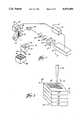
- FIG. 1broadly illustrates the apparatus 10 in accordance with the present invention.
- the apparatus 10includes a laser 12, powder dispenser 14, and laser control means 16.
- the powder dispenser 14includes a hopper 20 for receiving the powder 22 and having an outlet 24.
- the outlet 24is oriented for dispensing the powder to a target area 26, which in FIG. 1 is generally defined by the confinement structure 28.
- a target area 26which in FIG. 1 is generally defined by the confinement structure 28.
- many alternatives exist for dispensing the powder 22are possible.
- the components of the laser 12are shown somewhat schematically in FIG. 1 and include a laser head 30, a safety shutter 32, and a front mirror assembly 34.
- the type of laser usedis dependent upon many factors, and in particular upon the type of powder 22 that is to be sintered.
- a Nd:YAG laserLasermetrics 9500Q
- the laser beam output of the laser 12has a wavelength of approximately 1060 nm, which is near infrared.
- the laser 12 illustrated in FIG. 1includes an internal pulse rate generator with a selectable range of about one kiloHertz to forty kiloHertz, and an approximately six nanosecond pulse duration. In either the pulsed or continuous mode, the laser 12 can be modulated on or off to selectively produce a laser beam which travels generally along the path shown by the arrows in FIG. 1.
- a diverging lens 36 and converging lens 38are disposed along the path of travel of the laser beam as shown in FIG. 1.
- the diverging lens 36 placed between the laser 12 and converging lens 38creates a virtual focal point between the diverging lens 36 and the laser 12. Varying the distance between the converging lens 38 and the virtual vocal point, allows control of the true focal point along the laser beam path of travel on the side of the converging lens 38 remote from the laser 12.
- the laser control means 16includes computer 40 and scanning system 42.
- the computer 40includes a microprocessor for controlling the laser 12 and a CAD/CAM system for generating the data.
- a personal computeris used (Commodore 64) whose primary attributes include an accessible interface port and a flag line which generates a nonmaskable interrupt.
- the scanning system 42includes a prism 44 for redirecting the path of travel of the laser beam.
- the scanning system 42also includes a pair of mirrors 46, 47 driven by respective galvonometers 48, 49.
- the galvonometers 48, 49coupled to their respective mirrors 46, 47 to selectively orientate the mirrors 46, 47.
- the galvonometers 46, 47are mounted perpendicular to each other such that the mirrors 46, 47 are mounted nominally at a right angle to each other.
- a function generator driver 50controls the movement of the galvonometer 48 (galvonometer 49 is slaved to the movement of galvonometer 48) so that the aim of the laser beam (represented by the arrows in FIG. 1) can be controlled in the target area 26.
- the driver 50is operatively coupled to the computer 40 as shown in FIG. 1. It will be appreciated that alternative scanning methods are available for use as the scanning system 42, including acusto-optic scanners, rotating polygon mirrors, and resonant mirror scanners.
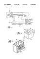
- FIG. 2 of the drawinga portion of a part 52 is schematically illustrated and shows four layers 54-57.
- the aim of the laser beam; labeled 64 in FIG. 2is directed in a raster scan pattern as at 66.
- "aim"is used as a neutral term indicating direction, but does not imply the modulation state of the laser 12.
- the axis 68is considered the fast scan axis, while the axis 70 is referred to as the slow scan axis.
- Axis 72is the direction of part build-up.
- FIGS. 9 and 10powders, comprising a plurality of materials by which parts may be made using the present invention, are illustrated. For simplicity, only two materials are shown in the illustrations. However, as will be apparent to one skilled in the art, a plurality of materials may comprise the powder of the present invention.
- FIG. 9illustrates a blend of first material 901 and second material 902. The materials are combined in a blend through conventional blending processes.
- FIG. 10illustrates material 1002 coated in material 1001. Material 1002 is coated using conventional coating processes.
- coated materialsmay be blended to produce a desired mix of materials.
- FIG. 11aillustrates a blend of materials prior to the application of energy able to produce sintering.
- the materials comprising powder mass 1100have more than one bonding or dissociation temperature.
- FIG. 11billustrates powder 1100 during application of energy sufficient to promote sintering.
- FIG. 11billustrates material 1101 having a lower bonding or dissociation temperature than material 1102.
- the low temperature phase material 1101melts and infiltrates powder mass 1100 in the area surrounding each particle of material 1101. Additional powder components could also be added to the blend to promote infiltration.
- a gas phasecan be used to promote infiltration and the sintering process.
- the gas phasemay be either inert or active, preferably to either displace an undesired gas or introduce a desired gas.
- FIG. 11cillustrates a potential mechanism through which effects, including but not limited to, capillarity effects, allow material 1101 to infiltrate the powder mass 1100.
- FIG. 11dshows the part following sintering in the present invention.
- the higher bonding or dissociation temperature materialneed not sinter but may retain its original structure.
- thisenables control of epitaxial growth in the selective beam sintering process of the present invention.
- the higher bonding or dissociation temperature materialis positioned in a particular structure that may, preferably, result in epitaxial growth from the preceding layer, only bonding or dissociating the lower bonding or dissociation temperature material enables the higher temperature material to retain its structure.
- a conducting materialis preferably coated with an insulating polymer material to produce a powder.
- the powderis then distributed in the target area.
- the materialis preferably sintered and the insulator may be removed later through a conventional process, including but not limited to a chemical method, resulting in a conductive, sintered product.
- tungsten carbide/cobalt toolswhich, because of their extreme hardness are difficult to form or sharpen may be produced by coating tungsten carbide material with cobalt to produce a powder or by blending tungsten carbide and cobalt to produce a powder. During sintering, the cobalt preferably melts under the applied energy beam causing local infiltration of the tungsten carbide. The part that is manufactured is ready to be put into service preferably after a secondary process including, but not limited to, annealing.
- copper and tinmay be combined in a powder. Tin, having a lower melting temperature than copper, will melt and infiltrate the copper during sintering.
- Secondary processingmay also be applied to parts produced using the present invention.
- post process annealingwill dissolve the tin into the copper in the solid state creating bronze with minimal volume change or distortion.
- metalincluding but not limited to, iron or steel
- PMMApoly(methyl methacrylate)
- Sinteringenables the PMMA to flow and bind the metal.
- Post process annealingwill dissociate the PMMA and sinter the metal thus producing a final part.
- Ceramic materialsmay be processed in this fashion as well.
- a mixture of fluorophosphate glass powders with alumina powderswill result in the glass softening and infiltrating the alumina during the sintering process.
- aluminum silicate, silica, or other ceramic powdercan be coated with a polymer by a variety of methods, including spray drying and solvent coating.
- a surface active agentmay be used to pretreat the ceramic powder prior to coating. This agent may be based on organosilane chemistry or other chemistries known to promote the wetability of the ceramic by the polymer and the adhesion of ceramic to polymer.
- Any polymer, either thermoplastic or thermoset, which can be coated on the ceramiccan be used as a binder. Typical materials include PMMA, polystyrene, various epoxy formulations, and phenolics.
- any combination of materialsincluding but not limited to, metals, ceramics and polymers enables production of parts in accordance with the present invention wherein at least one material in the powder has a low bonding or dissociation temperature relative to the other materials in the powder.
- the temperature of the powder massmay be increased using conventional heating means allowing the energy beam to merely supply a small increase of energy to produce bonding or dissociation of one of the elemental materials of the powder.
- Materials comprising the powdermay be chosen for each material's selective absorption of energy from a laser beam (represented by the arrows in FIGS. 11a and 11b).
- material 1101may be chosen to absorb the wavelength of the applied beam energy represented by the arrows while elemental material 1102 absorbs less energy thereby enabling elemental material 1101 to bond or dissociate prior to the bonding or dissociation of elemental material 1102.
- This absorption of energycan be achieved by either material or laser beam wavelength selection, or both, in a plurality of combinations.
- a material 1201is preferably deposited on surface 1200 and second material 1203 is then deposited on material 1201 prior to sintering.
- Materials 1201 and 1203preferably have different bonding or dissociation temperatures.
- a fundamental concept of the present inventionis the build up of a part in a layer-by-layer manner. That is, a part is considered a plurality of discrete cross-sectional regions which cumulatively comprise the three-dimensional configuration of the part. Each discrete cross-sectional region has defined two-dimensional boundaries--of course, each region may have unique boundaries.
- a first portion of powder 22is deposited in the target area 26 and selectively sintered by the laser beam 64 to produce a first sintered layer 54 (FIG. 2).
- the first sintered layer 54corresponds to a first cross-sectional region of the desired part.
- the laser beamselectively sinters only the deposited powder 22 within the confines of the defined boundaries.
- the raster modehas a disadvantage when compared to the vector mode in that arcs and lines which are not parallel to the axes 68, 70 of the raster pattern 66 of the laser beam 64 are only approximated. Thus, in some cases resolution of the part can be degraded when produced in the raster pattern mode.
- the raster modeis advantageous over the vector mode in the simplicity of implementation.
- the aim of the laser beam 64is scanned in the target area 26 in a continuous raster pattern.
- the driver 50controls galvonometers 48, 49 to made the raster pattern 66 (see FIG. 2).
- Shifting movement of the mirror 46controls movement of the aim of the laser beam 64 in the fast scan axis 68 (FIG. 2), while movement of the mirror 47 controls movement of the aim of the laser beam 64 in the slow scan access 70.
- the present position of the aim of the beam 64is fed back through the driver 50 to the computer 40 (see FIG. 3).
- the computer 40possesses information relating to the desired cross-sectional region of the part then being produced. That is, a portion of loose powder 22 is dispensed into the target area 26 and the aim of the laser beam 64 moved in its continuous raster pattern.
- the computer 40modulates the laser 12 to selectively produce a laser beam at desired intervals in the raster pattern 66. In this fashion, the directed beam of the laser 12 selectively sinters the powder 22 in the target area 26 to produce the desired sintered layer with the defined boundaries of the desired cross-sectional region. This process is repeated layer-by-layer with the individual layers sintered together to produce a cohesive part--e.g. part 52 of FIG. 2.
- the wavelength of laser 12may be varied to produce higher absorptivity of energy by selected materials in the powder relative to other materials in powder 22.
- blended, coated or other combinations of powdersare preferably selected to produce sintered product with characteristics including but not limited to, close dimensional tolerances, structural integrity and required mechanical behavior.
- the interface hardwareoperatively interconnects the computer 40 with the laser 12 and galvonometers 47, 48.
- the output port of the computer 40(see FIGS. 1 and 3) is directly connected to the laser 12 to selectively modulate the laser 12.
- the laser 12When operated in the pulsed mode, the laser 12 is easily controlled by digital inputs to the pulsed gate input of the laser.
- Galvonometer 48is driven by the function generator driver 50 to drive the beam in the fast scan axis 68 independent of any control signals from the computer 40. However, a position feedback signal from the galvonometer 48 is fed to a voltage comparator 74 as shown in FIG. 3.
- the other input to the comparatoris connected to the digital-to-analog convertor 76 which is indicative of the least significant six bits (bits 0-5) of the user port of the computer 40.
- the output of the voltage comparator 74is connected to the flag line on the user port of the computer 40.
- the galvonometer 49 driving the aim of the laser beam 64 in the slow scan axis 70is controlled by a second digital to analog convertor 78.
- the digital-to-analog convertor 78is driven by a counter 79 which increments with each sweep of the aim of the beam 64 in the fast scan axis 68.
- the eight byte counteris designed to overflow after 256 scans in the fast scan axis 68 to start a new cycle or raster scan pattern 66.
- control information data for each raster pattern 66would be determined by a CAD system given the overall dimensions and configuration of the part to be produced. Whether programmed or derived, the control information data for each raster pattern 66 is stored in the computer memory as a series of eight bit words.
- the data formatrepresents a pattern of "on” and “off” regions of the laser 12, versus distance along the raster pattern 66 traveled by the aim of the beam 64.
- the datais stored in a "toggle-point” format where the data represents the distance along each raster scan pattern 66 where the laser is modulated (i.e. turned from on to off or from off to on).
- a "bit map" formatmight be used, the toggle point format has been found more efficient for the production of high resolution parts.
- the least significant six bitsrepresent the location of the next toggle point--i.e. the next location for modulation of the laser 12.
- the next bitrepresents whether the laser is on or off immediately before the toggle point identified in the least significant six bits.
- the most significant bit(MSB or bit 7) is used for looping and for controlling the slow scan axis 70 of the aim of the beam 64. Because the Commodore 64 had limited memory, looping was required--it being understood that a computer 40 with more memory would not require looping.
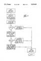
- FIG. 6represents the flow chart for the data metering program.
- the data metering programis run when ever the flagline goes low causing a non-maskable interrupt (see FIG. 3).
- the interruptcauses the microprocessor of the computer 40 to retrieve a two byte interrupt vector which points to the location in memory where program control is transferred at interrupt.
- the data metering programfirst pushes the registers onto the stack and then loads the next byte of data into the accumulator.
- the data wordis also output to the user port with the sixth bit used to modulate the laser 12 (FIG. 3).
- the most significant bit (MSB or bit 7) of the data word in the accumulatoris examined. If the value of the most significant bit is one, that means the end of the loop has not been reached; therefore the data pointer is incremented, registers are restored from the stack, and the data metering program is exited, returning control to the microprocessor at the location of interrupt. If the most significant bit in the accumulator is zero, the data word is the last word in the loop. If the data word is the last word in the loop, the next bit in memory is a loop counter and the following two bytes are a vector pointing to the top of the loop. As can be seen from FIG.
- the loop counter(next bit) is decremented and analyzed. If the loop counter is still greater than zero, the data pointer assumes the value from the next two memory bytes after the loop counter, registers are pulled from the stack and program control returns to the location of interrupt. On the other hand, if loop counter is zero, the data pointer is incremented by three and the loop counter is reset to ten before exiting the program. It can be appreciated that the need for such looping is absolved if the memory size of the computer 40 is adequate.
- FIGS. 4 and 5an example part 52 is illustrated.
- the example part 52assumes an unusual shape in that it is not symmetrical and would be difficult to fabricate using conventional machining methods.
- the part 52includes an outer base structure 80 having an interior cavity 82 and a pillar 84 disposed within the cavity 82 (see FIG. 4).
- FIG. 5shows the part 52 within the confinement structure 28 defining the target area 26 illustrated in FIG. 1. As shown in FIG. 5, some of the powder 22 is loose, while the remainder of the powder is selectively sintered to comprise the structure of the part 52.
- FIG. 5is shown in vertical section with parts broken away and outlined in phantom to show the sintered cohesive portions of the part 52.
- FIG. 7shows a horizontal cross-sectional region, taken along line 7--7 of FIG. 4.
- FIG. 7represents a discrete layer 86 associated with the cross-sectional region of the part being produced.
- the sintered layer 86 of FIG. 7is a product of a single raster pattern 66 as illustrated in FIG. 2.
- FIG. 8illustrates the software and hardware interface operation during the sweep L.
- the top graphshows the position of feedback signal from the fast axis galvo 48 and the output signal of the first digital to analog convertor 76 (compare FIG. 3).
- the voltage comparator 74generates an output signal to the flag line of the computer 40 every time the feedback signal and first D/A output signal cross.
- these pointsare labeled T to represent toggle points.
- the flag linegenerates a nonmaskable interrupt corresponding to each toggle point T.
- the sixth bit of each data wordis analyzed and the current state of the laser 12 will reflect the value.
- the penultimate graph of FIG. 8shows the laser modulation signal for the sweep line L of FIG. 7.
- the second graph of FIG. 8shows that a high-going edge in the most significant bit will be encountered at the end of each sweep of the aim of the laser beam 64 in the fast scan axis 68.
- the counter 79increments on a high going edge, and outputs a signal to the second digital-analog convertor 78 to drive the slow axis galvonometer 49.
- parts of complex shapecan be produced with relative ease.
- Those skilled in the artwill appreciate that the part 52 illustrated in FIG. 4 would be difficult to produce using conventional machining methods. In particular, machine tool access would make the fabrication of cavity 82 and pillar 84 difficult, if not impossible, to produce if the part 52 were of a relatively small size.
- the production accuracyis not dependent upon machine tool wear and the accuracy of mechanical components found in conventional machine tools. That is, the accuracy and tolerances of the parts produced by the method and apparatus of the present invention are primarily a function of the quality of the electronics, the optics, and the implementing software. Of course, heat transfer and material considerations do affect the tolerances obtainable.
- the apparatus of the present inventiononly requires the data relating to each cross-sectional region of the part being produced. While such data can be simply programmed into the computer 40, preferably, the computer 40 includes a CAD/CAM system. That is, the CAD/CAM portion of the computer 40 is given the overall dimensions and configurations of the desired part to be produced and the computer 40 determines the boundaries for each discrete cross-sectional region of the part.
- the apparatus 10produces a selected part without set-up time, part specific tooling, or human intervention. Even the complex and expensive dies associated with powder metallargy and conventional casting techniques are avoided.
- the method and apparatus 10 of the present inventionis useful in many contexts.
- prototype models and casting patternsare easily and inexpensively produced.
- casting patternsare easily made for use in sand casting, lost wax casting, or other forming techniques.
- desired quantitiesare very small, such as with obsolete replacement parts, production of such replacement parts using the apparatus 10 of the present invention has many advantages.
- the use of the apparatus 10may be useful where size of production facilities is a major constraint, such as on-ship or in outerspace.
Landscapes
- Engineering & Computer Science (AREA)
- Chemical & Material Sciences (AREA)
- Mechanical Engineering (AREA)
- Physics & Mathematics (AREA)
- Optics & Photonics (AREA)
- Materials Engineering (AREA)
- Manufacturing & Machinery (AREA)
- Plasma & Fusion (AREA)
- Organic Chemistry (AREA)
- Metallurgy (AREA)
- Chemical Kinetics & Catalysis (AREA)
- Composite Materials (AREA)
- Structural Engineering (AREA)
- General Physics & Mathematics (AREA)
- Automation & Control Theory (AREA)
- Human Computer Interaction (AREA)
- Theoretical Computer Science (AREA)
- Computing Systems (AREA)
- Ceramic Engineering (AREA)
- Civil Engineering (AREA)
- Powder Metallurgy (AREA)
Abstract
Description
Claims (20)
Priority Applications (7)
| Application Number | Priority Date | Filing Date | Title |
|---|---|---|---|
| US07/559,338US5076869A (en) | 1986-10-17 | 1990-07-30 | Multiple material systems for selective beam sintering |
| US07/624,419US5156697A (en) | 1989-09-05 | 1990-12-07 | Selective laser sintering of parts by compound formation of precursor powders |
| US07/692,172US5182170A (en) | 1989-09-05 | 1991-04-26 | Method of producing parts by selective beam interaction of powder with gas phase reactant |
| US07/854,246US5284695A (en) | 1989-09-05 | 1992-03-20 | Method of producing high-temperature parts by way of low-temperature sintering |
| US07/951,349US5296062A (en) | 1986-10-17 | 1992-09-25 | Multiple material systems for selective beam sintering |
| US08/044,971US5431967A (en) | 1989-09-05 | 1993-04-08 | Selective laser sintering using nanocomposite materials |
| US08/215,265US5382308A (en) | 1986-10-17 | 1994-03-21 | Multiple material systems for selective beam sintering |
Applications Claiming Priority (2)
| Application Number | Priority Date | Filing Date | Title |
|---|---|---|---|
| US06/920,580US4863538A (en) | 1986-10-17 | 1986-10-17 | Method and apparatus for producing parts by selective sintering |
| US07/559,338US5076869A (en) | 1986-10-17 | 1990-07-30 | Multiple material systems for selective beam sintering |
Related Parent Applications (1)
| Application Number | Title | Priority Date | Filing Date |
|---|---|---|---|
| US07/402,694ContinuationUS4944817A (en) | 1986-10-17 | 1989-09-05 | Multiple material systems for selective beam sintering |
Related Child Applications (4)
| Application Number | Title | Priority Date | Filing Date |
|---|---|---|---|
| US07/624,419Continuation-In-PartUS5156697A (en) | 1989-09-05 | 1990-12-07 | Selective laser sintering of parts by compound formation of precursor powders |
| US07/657,151Continuation-In-PartUS5147587A (en) | 1986-10-17 | 1991-02-19 | Method of producing parts and molds using composite ceramic powders |
| US07/692,172Continuation-In-PartUS5182170A (en) | 1989-09-05 | 1991-04-26 | Method of producing parts by selective beam interaction of powder with gas phase reactant |
| US81471591AContinuation | 1986-10-17 | 1991-12-30 |
Publications (1)
| Publication Number | Publication Date |
|---|---|
| US5076869Atrue US5076869A (en) | 1991-12-31 |
Family
ID=27072038
Family Applications (1)
| Application Number | Title | Priority Date | Filing Date |
|---|---|---|---|
| US07/559,338Expired - LifetimeUS5076869A (en) | 1986-10-17 | 1990-07-30 | Multiple material systems for selective beam sintering |
Country Status (1)
| Country | Link |
|---|---|
| US (1) | US5076869A (en) |
Cited By (217)
| Publication number | Priority date | Publication date | Assignee | Title |
|---|---|---|---|---|
| US5147587A (en)* | 1986-10-17 | 1992-09-15 | Board Of Regents, The University Of Texas System | Method of producing parts and molds using composite ceramic powders |
| US5182170A (en)* | 1989-09-05 | 1993-01-26 | Board Of Regents, The University Of Texas System | Method of producing parts by selective beam interaction of powder with gas phase reactant |
| US5284695A (en)* | 1989-09-05 | 1994-02-08 | Board Of Regents, The University Of Texas System | Method of producing high-temperature parts by way of low-temperature sintering |
| US5296062A (en)* | 1986-10-17 | 1994-03-22 | The Board Of Regents, The University Of Texas System | Multiple material systems for selective beam sintering |
| US5316580A (en)* | 1986-10-17 | 1994-05-31 | Board Of Regents, The University Of Texas System | Method and apparatus for producing parts by selective sintering |
| US5321622A (en)* | 1988-04-18 | 1994-06-14 | 3D Systems, Inc. | Boolean layer comparison slice |
| US5340656A (en)* | 1989-12-08 | 1994-08-23 | Massachusetts Institute Of Technology | Three-dimensional printing techniques |
| US5352405A (en)* | 1992-12-18 | 1994-10-04 | Dtm Corporation | Thermal control of selective laser sintering via control of the laser scan |
| US5431967A (en)* | 1989-09-05 | 1995-07-11 | Board Of Regents, The University Of Texas System | Selective laser sintering using nanocomposite materials |
| DE4433118A1 (en)* | 1994-09-16 | 1996-03-21 | Eos Electro Optical Syst | Process for producing a three-dimensional object |
| US5617911A (en)* | 1995-09-08 | 1997-04-08 | Aeroquip Corporation | Method and apparatus for creating a free-form three-dimensional article using a layer-by-layer deposition of a support material and a deposition material |
| US5639402A (en)* | 1994-08-08 | 1997-06-17 | Barlow; Joel W. | Method for fabricating artificial bone implant green parts |
| US5640667A (en)* | 1995-11-27 | 1997-06-17 | Board Of Regents, The University Of Texas System | Laser-directed fabrication of full-density metal articles using hot isostatic processing |
| US5648450A (en)* | 1992-11-23 | 1997-07-15 | Dtm Corporation | Sinterable semi-crystalline powder and near-fully dense article formed therein |
| US5660621A (en)* | 1995-12-29 | 1997-08-26 | Massachusetts Institute Of Technology | Binder composition for use in three dimensional printing |
| US5669433A (en)* | 1995-09-08 | 1997-09-23 | Aeroquip Corporation | Method for creating a free-form metal three-dimensional article using a layer-by-layer deposition of a molten metal |
| US5718951A (en)* | 1995-09-08 | 1998-02-17 | Aeroquip Corporation | Method and apparatus for creating a free-form three-dimensional article using a layer-by-layer deposition of a molten metal and deposition of a powdered metal as a support material |
| US5733497A (en)* | 1995-03-31 | 1998-03-31 | Dtm Corporation | Selective laser sintering with composite plastic material |
| US5746844A (en)* | 1995-09-08 | 1998-05-05 | Aeroquip Corporation | Method and apparatus for creating a free-form three-dimensional article using a layer-by-layer deposition of molten metal and using a stress-reducing annealing process on the deposited metal |
| US5749041A (en)* | 1995-10-13 | 1998-05-05 | Dtm Corporation | Method of forming three-dimensional articles using thermosetting materials |
| US5775402A (en)* | 1995-10-31 | 1998-07-07 | Massachusetts Institute Of Technology | Enhancement of thermal properties of tooling made by solid free form fabrication techniques |
| US5787965A (en)* | 1995-09-08 | 1998-08-04 | Aeroquip Corporation | Apparatus for creating a free-form metal three-dimensional article using a layer-by-layer deposition of a molten metal in an evacuation chamber with inert environment |
| US5814161A (en)* | 1992-11-30 | 1998-09-29 | Massachusetts Institute Of Technology | Ceramic mold finishing techniques for removing powder |
| US5851335A (en)* | 1996-01-30 | 1998-12-22 | Otis Elevator Company | Method and compositions for laser imprinting AND articles imprinted using such methods and compositions |
| US5902441A (en)* | 1996-09-04 | 1999-05-11 | Z Corporation | Method of three dimensional printing |
| US5990268A (en)* | 1992-11-23 | 1999-11-23 | Dtm Corporation | Sinterable semi-crystalline powder and near-fully dense article formed therewith |
| US6007318A (en)* | 1996-12-20 | 1999-12-28 | Z Corporation | Method and apparatus for prototyping a three-dimensional object |
| US6030199A (en)* | 1998-02-09 | 2000-02-29 | Arizona Board Of Regents, Acting For And On Behalf Of Arizona State University | Apparatus for freeform fabrication of a three-dimensional object |
| US6048954A (en)* | 1994-07-22 | 2000-04-11 | The University Of Texas System Board Of Regents | Binder compositions for laser sintering processes |
| US6085122A (en)* | 1997-05-30 | 2000-07-04 | Dtm Corporation | End-of-vector laser power control in a selective laser sintering system |
| US6151345A (en)* | 1998-07-07 | 2000-11-21 | Dtm Corporation | Laser power control with stretched initial pulses |
| US6155331A (en)* | 1994-05-27 | 2000-12-05 | Eos Gmbh Electro Optical Systems | Method for use in casting technology |
| US6355086B2 (en) | 1997-08-12 | 2002-03-12 | Rolls-Royce Corporation | Method and apparatus for making components by direct laser processing |
| US6396025B1 (en) | 1999-07-01 | 2002-05-28 | Aeromet Corporation | Powder feed nozzle for laser welding |
| USRE37875E1 (en) | 1997-04-30 | 2002-10-15 | John A. Lawton | Solid imaging process using component homogenization |
| EP1117518A4 (en)* | 1998-06-26 | 2003-01-29 | Stanford Res Inst Int | MANUFACTURE OF THREE-DIMENSIONAL OBJECTS |
| US6531191B1 (en)* | 1996-04-17 | 2003-03-11 | Koninklijke Philips Electronics N.V. | Method of manufacturing a sintered structure on a substrate |
| US6677554B2 (en) | 2001-07-31 | 2004-01-13 | 3D Systems, Inc. | Selective laser sintering with optimized raster scan direction |
| US20040009089A1 (en)* | 2002-07-12 | 2004-01-15 | Jianxin Liu | Blended powder solid-supersolidus liquid phase sintering |
| US20040018107A1 (en)* | 2002-07-23 | 2004-01-29 | Behrokh Khoshnevis | Metallic parts fabrication using selective inhibition of sintering (SIS) |
| US20040026418A1 (en)* | 2000-09-26 | 2004-02-12 | Ingo Ederer | Interchangeable container |
| US20040025905A1 (en)* | 2000-10-04 | 2004-02-12 | Ingo Ederer | Method for unpacking shaped bodies embedded inside unbound particle material |
| US6694207B2 (en) | 2001-07-31 | 2004-02-17 | 3D Systems, Inc. | Selective laser sintering with interleaved fill scan |
| US20040035542A1 (en)* | 2000-09-26 | 2004-02-26 | Ingo Ederer | Device for manufacturing models layer by layer |
| US20040056378A1 (en)* | 2002-09-25 | 2004-03-25 | Bredt James F. | Three dimensional printing material system and method |
| US6723278B1 (en) | 1998-11-12 | 2004-04-20 | The National University Of Singapore | Method of laser casting copper-based composites |
| US20040081573A1 (en)* | 2002-10-23 | 2004-04-29 | 3D Systems, Inc. | Binder removal in selective laser sintering |
| US20040081733A1 (en)* | 2000-04-14 | 2004-04-29 | Good Humor - Breyers Ice Cream | Process for extruding ice cream, apparatus for achieving such extrusion and products resulting therefrom |
| GB2395927A (en)* | 2002-12-02 | 2004-06-09 | Ono & Co Ltd | Producing artificial bones by laser sintering |
| US20040184944A1 (en)* | 2003-03-19 | 2004-09-23 | 3D Systems, Inc. | Metal powder composition for laser sintering |
| US20040226929A1 (en)* | 2003-02-26 | 2004-11-18 | Seiko Epson Corporation | Method for fixing functional material apparatus for fixing functional material, device fabrication method, electrooptical device, and electronic equipment |
| US20050017394A1 (en)* | 2003-06-16 | 2005-01-27 | Voxeljet Gmbh | Methods and systems for the manufacture of layered three-dimensional forms |
| US20050059757A1 (en)* | 2003-08-29 | 2005-03-17 | Z Corporation | Absorbent fillers for three-dimensional printing |
| US20050124720A1 (en)* | 2002-04-03 | 2005-06-09 | Mathys Medizinaltechnik Ag | Kneadable and pliable bone replacement material |
| US6989115B2 (en) | 1996-12-20 | 2006-01-24 | Z Corporation | Method and apparatus for prototyping a three-dimensional object |
| US20060045787A1 (en)* | 2004-08-30 | 2006-03-02 | Jandeska William F Jr | Aluminum/magnesium 3D-Printing rapid prototyping |
| EP1683593A2 (en) | 2004-12-30 | 2006-07-26 | Howmedica Osteonics Corp. | Laser produced porous structure |
| US20060175346A1 (en)* | 2002-05-20 | 2006-08-10 | Ingo Ederer | Device for feeding fluids |
| US20060237159A1 (en)* | 2003-06-17 | 2006-10-26 | Voxelet Gmbh | Method for the layered construction of models |
| US20070007699A1 (en)* | 2003-09-11 | 2007-01-11 | Extrude Hone Corporation | Layered manufactured articles having small-width fluid conduction vents and methods of making same |
| US20070029698A1 (en)* | 2003-09-11 | 2007-02-08 | Rynerson Michael L | Layered manufactured articles having small-diameter fluid conduction vents and method of making same |
| US20070142914A1 (en)* | 2005-12-06 | 2007-06-21 | Eric Jones | Laser-produced porous surface |
| US7261542B2 (en) | 2004-03-18 | 2007-08-28 | Desktop Factory, Inc. | Apparatus for three dimensional printing using image layers |
| US7291002B2 (en) | 2003-05-23 | 2007-11-06 | Z Corporation | Apparatus and methods for 3D printing |
| US20070288021A1 (en)* | 2006-06-07 | 2007-12-13 | Howmedica Osteonics Corp. | Flexible joint implant |
| US7332537B2 (en) | 1996-09-04 | 2008-02-19 | Z Corporation | Three dimensional printing material system and method |
| US20080233302A1 (en)* | 2004-05-24 | 2008-09-25 | Technische Universität Berlin | Method and Device for Production of a Three-Dimensional Article |
| US7435368B2 (en) | 1996-12-20 | 2008-10-14 | Z Corporation | Three-dimensional printer |
| US20080260945A1 (en)* | 2004-02-19 | 2008-10-23 | Ingo Ederer | Method and Device for Applying Fluids |
| US20080277837A1 (en)* | 2004-06-28 | 2008-11-13 | The Ex One Company | Gas Permeable Molds |
| US20090068245A1 (en)* | 2007-07-24 | 2009-03-12 | Noble Aaron M | Porous Laser Sintered Articles |
| US7531117B2 (en) | 2002-06-05 | 2009-05-12 | Ingo Ederer | Method for constructing patterns in a layered manner |
| US7537664B2 (en) | 2002-11-08 | 2009-05-26 | Howmedica Osteonics Corp. | Laser-produced porous surface |
| US7550518B2 (en) | 2000-04-14 | 2009-06-23 | Z Corporation | Methods and compositions for three-dimensional printing of solid objects |
| US7569273B2 (en) | 2003-05-21 | 2009-08-04 | Z Corporation | Thermoplastic powder material system for appearance models from 3D printing systems |
| US20100101982A1 (en)* | 2007-03-26 | 2010-04-29 | Intrexon Corporation | Classification method of particulate water absorbent resin |
| US7736578B2 (en) | 2006-06-30 | 2010-06-15 | Ingo Ederer | Method for the construction of a laminated compound |
| US7779890B2 (en) | 1998-11-20 | 2010-08-24 | Rolls-Royce Corporation | Method and apparatus for production of a cast component |
| US7795349B2 (en) | 1999-11-05 | 2010-09-14 | Z Corporation | Material systems and methods of three-dimensional printing |
| US20100244301A1 (en)* | 2007-10-11 | 2010-09-30 | Voxeljet Technology Gmbh | Material system and method for changing properties of a plastic component |
| US7828022B2 (en) | 2006-05-26 | 2010-11-09 | Z Corporation | Apparatus and methods for handling materials in a 3-D printer |
| US7879393B2 (en) | 2001-04-10 | 2011-02-01 | Ingo Ederer | Method and device for applying fluids |
| WO2011022560A1 (en) | 2009-08-19 | 2011-02-24 | Smith & Nephew, Inc. | Porous implant structures |
| US7905951B2 (en) | 2006-12-08 | 2011-03-15 | Z Corporation | Three dimensional printing material system and method using peroxide cure |
| WO2011020599A3 (en)* | 2009-08-18 | 2011-04-21 | Sintermask Gmbh | Method and device for producing a three-dimensional object |
| US7968626B2 (en) | 2007-02-22 | 2011-06-28 | Z Corporation | Three dimensional printing material system and method using plasticizer-assisted sintering |
| US8147861B2 (en) | 2006-08-15 | 2012-04-03 | Howmedica Osteonics Corp. | Antimicrobial implant |
| US8167999B2 (en) | 2007-01-10 | 2012-05-01 | 3D Systems, Inc. | Three-dimensional printing material system with improved color, article performance, and ease of use |
| US8221858B2 (en) | 2010-07-22 | 2012-07-17 | Stratasys, Inc. | Three-dimensional parts having porous protective structures |
| US8350186B2 (en) | 2005-12-30 | 2013-01-08 | Howmedica Osteonics Corp. | Laser-produced implants |
| US20130056269A1 (en)* | 2011-09-03 | 2013-03-07 | Baker Hughes Incorporated | Degradable shaped charge and perforating gun system |
| US8475946B1 (en) | 2007-03-20 | 2013-07-02 | Bowling Green State University | Ceramic article and method of manufacture |
| EP2647453A2 (en) | 2012-04-06 | 2013-10-09 | Howmedica Osteonics Corp. | Surface modified unit cell lattice structures for optimized secure freeform fabrication |
| US8568649B1 (en)* | 2007-03-20 | 2013-10-29 | Bowling Green State University | Three-dimensional printer, ceramic article and method of manufacture |
| WO2014011262A3 (en)* | 2012-04-05 | 2014-03-27 | United Technologies Corporation | Additive manufacturing hybrid core |
| US8715832B2 (en) | 2008-11-20 | 2014-05-06 | Voxeljet Ag | Method for the layered construction of plastic models |
| WO2014071135A1 (en) | 2012-11-01 | 2014-05-08 | General Electric Company | Additive manufacturing method and apparatus |
| US8727672B2 (en) | 2007-10-21 | 2014-05-20 | Voxeljet Ag | Method and device for conveying particulate material during the layer-wise production of patterns |
| US8741194B1 (en) | 2000-09-25 | 2014-06-03 | Voxeljet Ag | Method for producing a part using a depostion technique |
| US8801990B2 (en) | 2010-09-17 | 2014-08-12 | Stratasys, Inc. | Method for building three-dimensional models in extrusion-based additive manufacturing systems using core-shell semi-crystalline consumable filaments |
| US8828116B2 (en) | 2010-05-25 | 2014-09-09 | Panasonic Corporation | Metal powder for selective laser sintering, method for manufacturing three-dimensional shaped object by using the same, and three-dimensional shaped object obtained therefrom |
| US8851151B2 (en) | 1998-11-20 | 2014-10-07 | Rolls-Royce Corporation | Method and apparatus for production of a cast component |
| US8911226B2 (en) | 2010-04-14 | 2014-12-16 | Voxeljet Ag | Device for producing three-dimensional models |
| US8920697B2 (en) | 2010-09-17 | 2014-12-30 | Stratasys, Inc. | Method for building three-dimensional objects in extrusion-based additive manufacturing systems using core-shell consumable filaments |
| US8956144B2 (en) | 2010-02-04 | 2015-02-17 | Voxeijet AG | Device for producing three-demensional models |
| US8992205B2 (en) | 2007-10-23 | 2015-03-31 | Voxeijet AG | Device for the layer-wise production of patterns |
| US9022107B2 (en) | 2009-12-08 | 2015-05-05 | Baker Hughes Incorporated | Dissolvable tool |
| US9033055B2 (en) | 2011-08-17 | 2015-05-19 | Baker Hughes Incorporated | Selectively degradable passage restriction and method |
| US9057242B2 (en) | 2011-08-05 | 2015-06-16 | Baker Hughes Incorporated | Method of controlling corrosion rate in downhole article, and downhole article having controlled corrosion rate |
| US9068428B2 (en) | 2012-02-13 | 2015-06-30 | Baker Hughes Incorporated | Selectively corrodible downhole article and method of use |
| US9080098B2 (en) | 2011-04-28 | 2015-07-14 | Baker Hughes Incorporated | Functionally gradient composite article |
| US9079246B2 (en) | 2009-12-08 | 2015-07-14 | Baker Hughes Incorporated | Method of making a nanomatrix powder metal compact |
| US9090955B2 (en) | 2010-10-27 | 2015-07-28 | Baker Hughes Incorporated | Nanomatrix powder metal composite |
| US9090956B2 (en) | 2011-08-30 | 2015-07-28 | Baker Hughes Incorporated | Aluminum alloy powder metal compact |
| US9101978B2 (en) | 2002-12-08 | 2015-08-11 | Baker Hughes Incorporated | Nanomatrix powder metal compact |
| US9109429B2 (en) | 2002-12-08 | 2015-08-18 | Baker Hughes Incorporated | Engineered powder compact composite material |
| US9109269B2 (en) | 2011-08-30 | 2015-08-18 | Baker Hughes Incorporated | Magnesium alloy powder metal compact |
| US9127515B2 (en) | 2010-10-27 | 2015-09-08 | Baker Hughes Incorporated | Nanomatrix carbon composite |
| US9135374B2 (en) | 2012-04-06 | 2015-09-15 | Howmedica Osteonics Corp. | Surface modified unit cell lattice structures for optimized secure freeform fabrication |
| US9139928B2 (en) | 2011-06-17 | 2015-09-22 | Baker Hughes Incorporated | Corrodible downhole article and method of removing the article from downhole environment |
| US9174391B2 (en) | 2010-03-31 | 2015-11-03 | Voxeljet Ag | Device for producing three-dimensional models |
| US9187990B2 (en) | 2011-09-03 | 2015-11-17 | Baker Hughes Incorporated | Method of using a degradable shaped charge and perforating gun system |
| US9227243B2 (en) | 2009-12-08 | 2016-01-05 | Baker Hughes Incorporated | Method of making a powder metal compact |
| US9243475B2 (en) | 2009-12-08 | 2016-01-26 | Baker Hughes Incorporated | Extruded powder metal compact |
| US9242413B2 (en) | 2011-01-05 | 2016-01-26 | Voxeljet Ag | Device and method for constructing a laminar body comprising at least one position adjustable body defining the working area |
| US9267347B2 (en) | 2009-12-08 | 2016-02-23 | Baker Huges Incorporated | Dissolvable tool |
| US9333709B2 (en) | 2010-03-31 | 2016-05-10 | Voxeljet Ag | Device and method for producing three-dimensional models |
| US9347119B2 (en) | 2011-09-03 | 2016-05-24 | Baker Hughes Incorporated | Degradable high shock impedance material |
| US9364896B2 (en) | 2012-02-07 | 2016-06-14 | Medical Modeling Inc. | Fabrication of hybrid solid-porous medical implantable devices with electron beam melting technology |
| US9505176B2 (en) | 2007-07-18 | 2016-11-29 | Voxeljet Ag | Method for producing three-dimensional components |
| US9523934B2 (en) | 2013-07-17 | 2016-12-20 | Stratasys, Inc. | Engineering-grade consumable materials for electrophotography-based additive manufacturing |
| US9592530B2 (en) | 2012-11-21 | 2017-03-14 | Stratasys, Inc. | Additive manufacturing with polyamide consumable materials |
| US9605508B2 (en) | 2012-05-08 | 2017-03-28 | Baker Hughes Incorporated | Disintegrable and conformable metallic seal, and method of making the same |
| US9643360B2 (en) | 2006-08-20 | 2017-05-09 | Voxeljet Ag | Self-hardening material and process for layerwise formation of models |
| US9643144B2 (en) | 2011-09-02 | 2017-05-09 | Baker Hughes Incorporated | Method to generate and disperse nanostructures in a composite material |
| US9682425B2 (en) | 2009-12-08 | 2017-06-20 | Baker Hughes Incorporated | Coated metallic powder and method of making the same |
| WO2017117041A1 (en) | 2015-12-28 | 2017-07-06 | Matheson Tri-Gas, Inc. | Use of reactive fluids in additive manufacturing and the products made therefrom |
| US9707739B2 (en) | 2011-07-22 | 2017-07-18 | Baker Hughes Incorporated | Intermetallic metallic composite, method of manufacture thereof and articles comprising the same |
| US9714318B2 (en) | 2013-07-26 | 2017-07-25 | Stratasys, Inc. | Polyglycolic acid support material for additive manufacturing systems |
| US9718218B2 (en) | 2012-03-13 | 2017-08-01 | Structured Polymers, Inc. | Materials for powder-based additive manufacturing processes |
| US9744722B2 (en) | 2012-11-21 | 2017-08-29 | Stratasys, Inc. | Additive manufacturing with polyamide consumable materials |
| US9770867B2 (en) | 2010-12-29 | 2017-09-26 | Voxeljet Ag | Method and material system for building models in layers |
| WO2017179052A1 (en) | 2016-04-11 | 2017-10-19 | Stratasys Ltd. | Method and apparatus for additive manufacturing with powder material |
| US9816339B2 (en) | 2013-09-03 | 2017-11-14 | Baker Hughes, A Ge Company, Llc | Plug reception assembly and method of reducing restriction in a borehole |
| US9833838B2 (en) | 2011-07-29 | 2017-12-05 | Baker Hughes, A Ge Company, Llc | Method of controlling the corrosion rate of alloy particles, alloy particle with controlled corrosion rate, and articles comprising the particle |
| US9856547B2 (en) | 2011-08-30 | 2018-01-02 | Bakers Hughes, A Ge Company, Llc | Nanostructured powder metal compact |
| US9910026B2 (en) | 2015-01-21 | 2018-03-06 | Baker Hughes, A Ge Company, Llc | High temperature tracers for downhole detection of produced water |
| US9914169B2 (en) | 2010-04-17 | 2018-03-13 | Voxeljet Ag | Method and device for producing three-dimensional models |
| US9926766B2 (en) | 2012-01-25 | 2018-03-27 | Baker Hughes, A Ge Company, Llc | Seat for a tubular treating system |
| US9945419B2 (en) | 2013-08-27 | 2018-04-17 | The Timken Company | Retainer |
| US9943981B2 (en) | 2013-12-11 | 2018-04-17 | Voxeljet Ag | 3D infiltration method |
| US9969930B2 (en) | 2013-08-15 | 2018-05-15 | Halliburton Energy Services, Inc. | Additive fabrication of proppants |
| US10016811B2 (en) | 2013-08-09 | 2018-07-10 | David J. Neal | Orthopedic implants and methods of manufacturing orthopedic implants |
| US10016810B2 (en) | 2015-12-14 | 2018-07-10 | Baker Hughes, A Ge Company, Llc | Methods of manufacturing degradable tools using a galvanic carrier and tools manufactured thereof |
| US10022797B2 (en) | 2010-02-17 | 2018-07-17 | Panasonic Intellectual Property Management Co., Ltd. | Method for manufacturing three-dimensional shaped object and three-dimensional shaped object |
| US10052682B2 (en) | 2012-10-12 | 2018-08-21 | Voxeljet Ag | 3D multi-stage method |
| US10059058B2 (en) | 2012-06-22 | 2018-08-28 | Voxeljet Ag | Device for building a multilayer structure with storage container or filling container movable along the dispensing container |
| US10059053B2 (en) | 2014-11-04 | 2018-08-28 | Stratasys, Inc. | Break-away support material for additive manufacturing |
| US10059062B2 (en) | 2012-05-25 | 2018-08-28 | Voxeljet Ag | Device for producing three-dimensional models with special building platforms and drive systems |
| US20180253774A1 (en)* | 2009-05-19 | 2018-09-06 | Cobra Golf Incorporated | Method and system for making golf club components |
| WO2018173048A1 (en) | 2017-03-20 | 2018-09-27 | Stratasys Ltd. | Method and system for additive manufacturing with powder material |
| WO2018173050A1 (en) | 2017-03-20 | 2018-09-27 | Stratasys Ltd. | Method and system for additive manufacturing with powder material |
| US10092953B2 (en) | 2011-07-29 | 2018-10-09 | Baker Hughes, A Ge Company, Llc | Method of controlling the corrosion rate of alloy particles, alloy particle with controlled corrosion rate, and articles comprising the particle |
| EP3415298A1 (en) | 2017-06-15 | 2018-12-19 | Howmedica Osteonics Corporation | Porous structures produced by additive layer manufacturing |
| US10213831B2 (en) | 2012-11-25 | 2019-02-26 | Voxeljet Ag | Construction of a 3D printing device for producing components |
| US10221637B2 (en) | 2015-08-11 | 2019-03-05 | Baker Hughes, A Ge Company, Llc | Methods of manufacturing dissolvable tools via liquid-solid state molding |
| US10220567B2 (en) | 2012-03-06 | 2019-03-05 | Voxeljet Ag | Method and device for producing three-dimensional models |
| US10220568B2 (en) | 2013-12-02 | 2019-03-05 | Voxeljet Ag | Interchangeable container with moveable side walls |
| US10226919B2 (en) | 2007-07-18 | 2019-03-12 | Voxeljet Ag | Articles and structures prepared by three-dimensional printing method |
| US10240419B2 (en) | 2009-12-08 | 2019-03-26 | Baker Hughes, A Ge Company, Llc | Downhole flow inhibition tool and method of unplugging a seat |
| EP3479798A2 (en) | 2017-11-03 | 2019-05-08 | Howmedica Osteonics Corp. | Flexible construct for femoral reconstruction |
| US10307935B2 (en) | 2015-12-22 | 2019-06-04 | Structured Polymers, Inc. | Systems and methods for producing consumable powder |
| US10327916B2 (en) | 2014-07-03 | 2019-06-25 | Howmedica Osteonics Corp. | Impact absorbing pad |
| US10335858B2 (en) | 2011-04-28 | 2019-07-02 | Baker Hughes, A Ge Company, Llc | Method of making and using a functionally gradient composite tool |
| US10338742B2 (en) | 2017-03-02 | 2019-07-02 | Microsoft Technology Licensing, Llc | Detection method for a digitizer |
| US10343301B2 (en) | 2013-02-28 | 2019-07-09 | Voxeljet Ag | Process for producing a moulding using a water-soluble casting mould and material system for the production thereof |
| WO2019140240A1 (en) | 2018-01-11 | 2019-07-18 | K2M, Inc. | Implants and instruments with flexible features |
| US10378303B2 (en) | 2015-03-05 | 2019-08-13 | Baker Hughes, A Ge Company, Llc | Downhole tool and method of forming the same |
| US10442170B2 (en) | 2013-12-20 | 2019-10-15 | Voxeljet Ag | Device, special paper, and method for producing shaped articles |
| US10449692B2 (en) | 2014-12-08 | 2019-10-22 | Tethon Corporation | Three-dimensional (3D) printing |
| US10596660B2 (en) | 2015-12-15 | 2020-03-24 | Howmedica Osteonics Corp. | Porous structures produced by additive layer manufacturing |
| CN111203542A (en)* | 2019-12-03 | 2020-05-29 | 同济大学 | An integrated equipment for powder hot pressing |
| US10682809B2 (en) | 2014-12-22 | 2020-06-16 | Voxeljet Ag | Method and device for producing 3D moulded parts by means of a layer construction technique |
| US10780498B2 (en)* | 2018-08-22 | 2020-09-22 | General Electric Company | Porous tools and methods of making the same |
| US10786945B2 (en) | 2013-10-30 | 2020-09-29 | Voxeljet Ag | Method and device for producing three-dimensional models using a binding agent system |
| US10843404B2 (en) | 2015-05-20 | 2020-11-24 | Voxeljet Ag | Phenolic resin method |
| US10913207B2 (en) | 2014-05-26 | 2021-02-09 | Voxeljet Ag | 3D reverse printing method and device |
| WO2021028797A1 (en) | 2019-08-09 | 2021-02-18 | Ing-3D Ug | Method for producing an additively manufactured product from a mineral starting material by means of direct laser sintering, and lightweight part produced by means of said method |
| US10946556B2 (en) | 2014-08-02 | 2021-03-16 | Voxeljet Ag | Method and casting mold, in particular for use in cold casting methods |
| US10994333B2 (en) | 2014-05-08 | 2021-05-04 | Stratasys Ltd. | Method and apparatus for 3D printing by selective sintering |
| US11007600B2 (en) | 2013-06-10 | 2021-05-18 | Grid Logic Incorporated | System and method for additive manufacturing |
| US11065126B2 (en) | 2018-08-09 | 2021-07-20 | Stryker European Operations Holdings Llc | Interbody implants and optimization features thereof |
| US11097469B2 (en) | 2012-10-15 | 2021-08-24 | Voxeljet Ag | Method and device for producing three-dimensional models with a temperature-controllable print head |
| US11097471B2 (en) | 2014-03-31 | 2021-08-24 | Voxeljet Ag | Method and device for 3D printing using temperature-controlled processing |
| US11148319B2 (en) | 2016-01-29 | 2021-10-19 | Seurat Technologies, Inc. | Additive manufacturing, bond modifying system and method |
| US11148374B2 (en) | 2012-11-21 | 2021-10-19 | Stratasys, Inc. | Feedstock material for printing three-dimensional parts with crystallization kinetics control |
| US11167375B2 (en) | 2018-08-10 | 2021-11-09 | The Research Foundation For The State University Of New York | Additive manufacturing processes and additively manufactured products |
| US11167343B2 (en) | 2014-02-21 | 2021-11-09 | Terves, Llc | Galvanically-active in situ formed particles for controlled rate dissolving tools |
| US11235518B2 (en) | 2015-12-01 | 2022-02-01 | Voxeljet Ag | Method and device for producing three-dimensional components with the aid of an overfeed sensor |
| US20220055103A1 (en)* | 2020-08-24 | 2022-02-24 | Kennametal Inc. | Method for fabricating a three-dimensional metal part using a conformable fugitive material |
| WO2022072816A2 (en) | 2020-10-02 | 2022-04-07 | K2M, Inc. | Spinal interbody implants |
| US11298747B2 (en) | 2017-05-18 | 2022-04-12 | Howmedica Osteonics Corp. | High fatigue strength porous structure |
| WO2022081695A1 (en) | 2020-10-14 | 2022-04-21 | K2M, Inc. | Spinal interbody implants |
| US11365164B2 (en) | 2014-02-21 | 2022-06-21 | Terves, Llc | Fluid activated disintegrating metal system |
| US11446739B2 (en) | 2016-02-03 | 2022-09-20 | Grid Logic Incorporated | System and method for manufacturing a part |
| US11504879B2 (en) | 2020-04-17 | 2022-11-22 | Beehive Industries, LLC | Powder spreading apparatus and system |
| US11534257B2 (en) | 2018-11-20 | 2022-12-27 | Howmedica Osteonics Corp. | Lattice impaction pad |
| US11589996B2 (en) | 2020-03-25 | 2023-02-28 | Encore Medical, Lp | Joint implants having porous structures formed utilizing additive manufacturing and related systems and methods |
| US11618212B2 (en)* | 2019-03-20 | 2023-04-04 | Desktop Metal, Inc. | Additive fabrication of sinterable metallic parts via application of directed energy |
| US11649526B2 (en) | 2017-07-27 | 2023-05-16 | Terves, Llc | Degradable metal matrix composite |
| US11813672B2 (en) | 2020-05-08 | 2023-11-14 | Grid Logic Incorporated | System and method for manufacturing a part |
| US12018356B2 (en) | 2014-04-18 | 2024-06-25 | Terves Inc. | Galvanically-active in situ formed particles for controlled rate dissolving tools |
| US12059354B2 (en)* | 2019-02-15 | 2024-08-13 | Howmedica Osteonics Corp. | Robotic acetabulum preparation for acceptance of acetabular cup with engagement features |
| US12064917B2 (en) | 2012-11-21 | 2024-08-20 | Stratasys, Inc. | Method for printing three-dimensional parts with cyrstallization kinetics control |
| US12243085B1 (en) | 2009-05-19 | 2025-03-04 | Cobra Golf Incorporated | Method and system for sales of golf equipment |
| US12286689B2 (en) | 2017-02-24 | 2025-04-29 | Ohio State Innovation Foundation | Titanium alloys for additive manufacturing |
| US12397502B1 (en) | 2021-12-20 | 2025-08-26 | Desktop Metal, Inc. | Polymer-synthesizing binder compositions for additive fabrication and related methods and compositions |
Citations (22)
| Publication number | Priority date | Publication date | Assignee | Title |
|---|---|---|---|---|
| US2076952A (en)* | 1934-06-08 | 1937-04-13 | Kratky Anton | Production of hard metal alloys |
| GB1215184A (en)* | 1968-07-02 | 1970-12-09 | Chelton Forming Ltd | Improvements in or relating to the making of hollow articles by metal spraying |
| DE2263777A1 (en)* | 1971-12-28 | 1973-07-05 | Ciraud Leone Isaure Marie | METHOD AND DEVICE FOR MANUFACTURING ANY ARTICLES FROM ANY MELTABLE MATERIAL |
| US3985995A (en)* | 1973-04-19 | 1976-10-12 | August Thyssen-Hutte Aktienges. | Method of making large structural one-piece parts of metal, particularly one-piece shafts |
| US4117302A (en)* | 1974-03-04 | 1978-09-26 | Caterpillar Tractor Co. | Method for fusibly bonding a coating material to a metal article |
| US4135902A (en)* | 1978-03-03 | 1979-01-23 | Western Electric Co., Inc. | Method and apparatus for drawing optical fibers |
| DD137951A1 (en)* | 1978-07-21 | 1979-10-03 | Banke Karl Heinz | METHOD FOR DIRECTING TEXTILE STRUCTURES |
| US4270675A (en)* | 1979-10-29 | 1981-06-02 | United Technologies Corporation | Powder feed apparatus |
| US4300474A (en)* | 1979-03-30 | 1981-11-17 | Rolls-Royce Limited | Apparatus for application of metallic coatings to metallic substrates |
| US4323756A (en)* | 1979-10-29 | 1982-04-06 | United Technologies Corporation | Method for fabricating articles by sequential layer deposition |
| JPS5945089A (en)* | 1982-09-09 | 1984-03-13 | Toshiba Corp | Build-up welding method |
| JPS5976689A (en)* | 1982-10-22 | 1984-05-01 | Fujitsu Ltd | Hermetic sealing method for aluminum package |
| US4474861A (en)* | 1983-03-09 | 1984-10-02 | Smith International, Inc. | Composite bearing structure of alternating hard and soft metal, and process for making the same |
| US4540867A (en)* | 1984-06-25 | 1985-09-10 | Motorola, Inc. | Linearized scanning system and method for an energy beam |
| US4575330A (en)* | 1984-08-08 | 1986-03-11 | Uvp, Inc. | Apparatus for production of three-dimensional objects by stereolithography |
| US4587396A (en)* | 1982-12-31 | 1986-05-06 | Laser Industries Ltd. | Control apparatus particularly useful for controlling a laser |
| EP0209366A1 (en)* | 1985-07-17 | 1987-01-21 | Toyota Jidosha Kabushiki Kaisha | Method for padding a copper alloy material upon a base of aluminum metal or aluminium alloy using laser beam oscillating transversely to its tracking direction |
| WO1988002677A2 (en)* | 1986-10-17 | 1988-04-21 | Board Of Regents, The University Of Texas System | Method and apparatus for producing parts by selective sintering |
| US4752352A (en)* | 1986-06-06 | 1988-06-21 | Michael Feygin | Apparatus and method for forming an integral object from laminations |
| US4818562A (en)* | 1987-03-04 | 1989-04-04 | Westinghouse Electric Corp. | Casting shapes |
| US4863538A (en)* | 1986-10-17 | 1989-09-05 | Board Of Regents, The University Of Texas System | Method and apparatus for producing parts by selective sintering |
| US4944817A (en)* | 1986-10-17 | 1990-07-31 | Board Of Regents, The University Of Texas System | Multiple material systems for selective beam sintering |
- 1990
- 1990-07-30USUS07/559,338patent/US5076869A/ennot_activeExpired - Lifetime
Patent Citations (25)
| Publication number | Priority date | Publication date | Assignee | Title |
|---|---|---|---|---|
| US2076952A (en)* | 1934-06-08 | 1937-04-13 | Kratky Anton | Production of hard metal alloys |
| GB1215184A (en)* | 1968-07-02 | 1970-12-09 | Chelton Forming Ltd | Improvements in or relating to the making of hollow articles by metal spraying |
| DE2263777A1 (en)* | 1971-12-28 | 1973-07-05 | Ciraud Leone Isaure Marie | METHOD AND DEVICE FOR MANUFACTURING ANY ARTICLES FROM ANY MELTABLE MATERIAL |
| FR2166526A5 (en)* | 1971-12-28 | 1973-08-17 | Boudet Jean | Concentrated beam particle melting - at focal point of several beams |
| US3985995A (en)* | 1973-04-19 | 1976-10-12 | August Thyssen-Hutte Aktienges. | Method of making large structural one-piece parts of metal, particularly one-piece shafts |
| US4117302A (en)* | 1974-03-04 | 1978-09-26 | Caterpillar Tractor Co. | Method for fusibly bonding a coating material to a metal article |
| US4135902A (en)* | 1978-03-03 | 1979-01-23 | Western Electric Co., Inc. | Method and apparatus for drawing optical fibers |
| DD137951A1 (en)* | 1978-07-21 | 1979-10-03 | Banke Karl Heinz | METHOD FOR DIRECTING TEXTILE STRUCTURES |
| US4300474A (en)* | 1979-03-30 | 1981-11-17 | Rolls-Royce Limited | Apparatus for application of metallic coatings to metallic substrates |
| US4270675A (en)* | 1979-10-29 | 1981-06-02 | United Technologies Corporation | Powder feed apparatus |
| US4323756A (en)* | 1979-10-29 | 1982-04-06 | United Technologies Corporation | Method for fabricating articles by sequential layer deposition |
| JPS5945089A (en)* | 1982-09-09 | 1984-03-13 | Toshiba Corp | Build-up welding method |
| JPS5976689A (en)* | 1982-10-22 | 1984-05-01 | Fujitsu Ltd | Hermetic sealing method for aluminum package |
| US4587396A (en)* | 1982-12-31 | 1986-05-06 | Laser Industries Ltd. | Control apparatus particularly useful for controlling a laser |
| US4474861A (en)* | 1983-03-09 | 1984-10-02 | Smith International, Inc. | Composite bearing structure of alternating hard and soft metal, and process for making the same |
| US4540867A (en)* | 1984-06-25 | 1985-09-10 | Motorola, Inc. | Linearized scanning system and method for an energy beam |
| US4575330A (en)* | 1984-08-08 | 1986-03-11 | Uvp, Inc. | Apparatus for production of three-dimensional objects by stereolithography |
| US4575330B1 (en)* | 1984-08-08 | 1989-12-19 | ||
| EP0209366A1 (en)* | 1985-07-17 | 1987-01-21 | Toyota Jidosha Kabushiki Kaisha | Method for padding a copper alloy material upon a base of aluminum metal or aluminium alloy using laser beam oscillating transversely to its tracking direction |
| US4752352A (en)* | 1986-06-06 | 1988-06-21 | Michael Feygin | Apparatus and method for forming an integral object from laminations |
| WO1988002677A2 (en)* | 1986-10-17 | 1988-04-21 | Board Of Regents, The University Of Texas System | Method and apparatus for producing parts by selective sintering |
| US4863538A (en)* | 1986-10-17 | 1989-09-05 | Board Of Regents, The University Of Texas System | Method and apparatus for producing parts by selective sintering |
| US4938816A (en)* | 1986-10-17 | 1990-07-03 | Board Of Regents, The University Of Texas System | Selective laser sintering with assisted powder handling |
| US4944817A (en)* | 1986-10-17 | 1990-07-31 | Board Of Regents, The University Of Texas System | Multiple material systems for selective beam sintering |
| US4818562A (en)* | 1987-03-04 | 1989-04-04 | Westinghouse Electric Corp. | Casting shapes |
Non-Patent Citations (22)
| Title |
|---|
| "`Revolutionary`-Machine Makes 3-D Objects from Drawings", Austin-American Statesman (Dec. 4, 1987). |
| "Device Quickly Builds Models of a Computer's Designs", New York Times (Mar. 16, 1988), p. 46. |
| Deckard, "Part Generation by Layerwise Selective Sintering", May 1986. |
| Deckard, "Solid Freeform Fabrication and Selective Powder Sintering", Presented at NAMRACIS (1987) pp. 636-640. |
| Deckard, et al., "Process and Control Issues in Selective Laser Sintering", Measurement and Control in Manufacturing (ASME, 1988) pp. 191-197. |
| Deckard, et al., "Recent Advances in Selective Laser Sintering", Presented at 14th Conf. on Production Research and Technology (U. of Mich., 1987) pp. 447-451. |
| Deckard, et al., Process and Control Issues in Selective Laser Sintering , Measurement and Control in Manufacturing (ASME, 1988) pp. 191 197.* |
| Deckard, et al., Recent Advances in Selective Laser Sintering , Presented at 14th Conf. on Production Research and Technology (U. of Mich., 1987) pp. 447 451.* |
| Deckard, Part Generation by Layerwise Selective Sintering , May 1986.* |
| Deckard, Solid Freeform Fabrication and Selective Powder Sintering , Presented at NAMRACIS (1987) pp. 636 640.* |
| Device Quickly Builds Models of a Computer s Designs , New York Times (Mar. 16, 1988), p. 46.* |
| Fudim, "Sculpting Parts With Light", Machine Design, Mar. 6, 1986. |
| Fudim, Sculpting Parts With Light , Machine Design, Mar. 6, 1986.* |
| Immediate Production of 3 D Objects, Hydronetics, Inc.* |
| Immediate Production of 3-D Objects, Hydronetics, Inc. |
| Lasers Carve Complex 3 D Parts (pp. 1 11).* |
| Lasers Carve Complex 3-D Parts (pp. 1-11). |
| Leont ev, Lazernaja Poverhnostnaja Obrabotka Metallov I Splavov, (1986), pp. 120 123 (partial translation included).* |
| Leont'ev, Lazernaja Poverhnostnaja Obrabotka Metallov I Splavov, (1986), pp. 120-123 (partial translation included). |
| Revolutionary Machine Makes 3 D Objects from Drawings , Austin American Statesman (Dec. 4, 1987).* |
| Takei, et al., "Rhenium Film Preparation by Laser Melting", J. Appl. Phys. 51(5) (May 1980) pp. 2903-2908. |
| Takei, et al., Rhenium Film Preparation by Laser Melting , J. Appl. Phys. 51(5) (May 1980) pp. 2903 2908.* |
Cited By (399)
| Publication number | Priority date | Publication date | Assignee | Title |
|---|---|---|---|---|
| US5616294A (en)* | 1986-10-17 | 1997-04-01 | Board Of Regents, The University Of Texas System | Method for producing parts by infiltration of porous intermediate parts |
| US5597589A (en)* | 1986-10-17 | 1997-01-28 | Board Of Regents, The University Of Texas System | Apparatus for producing parts by selective sintering |
| US5296062A (en)* | 1986-10-17 | 1994-03-22 | The Board Of Regents, The University Of Texas System | Multiple material systems for selective beam sintering |
| US5316580A (en)* | 1986-10-17 | 1994-05-31 | Board Of Regents, The University Of Texas System | Method and apparatus for producing parts by selective sintering |
| US5147587A (en)* | 1986-10-17 | 1992-09-15 | Board Of Regents, The University Of Texas System | Method of producing parts and molds using composite ceramic powders |
| US5382308A (en)* | 1986-10-17 | 1995-01-17 | Board Of Regents, The University Of Texas System | Multiple material systems for selective beam sintering |
| US5639070A (en)* | 1986-10-17 | 1997-06-17 | Board Of Regents, The University Of Texas System | Method for producing parts by selective sintering |
| US5481470A (en)* | 1988-04-18 | 1996-01-02 | 3D Systems, Inc. | Boolean layer comparison slice |
| US5321622A (en)* | 1988-04-18 | 1994-06-14 | 3D Systems, Inc. | Boolean layer comparison slice |
| US5854748A (en)* | 1988-04-18 | 1998-12-29 | 3D Systems, Inc. | Boolean layer comparison slice |
| US5431967A (en)* | 1989-09-05 | 1995-07-11 | Board Of Regents, The University Of Texas System | Selective laser sintering using nanocomposite materials |
| US5284695A (en)* | 1989-09-05 | 1994-02-08 | Board Of Regents, The University Of Texas System | Method of producing high-temperature parts by way of low-temperature sintering |
| US5182170A (en)* | 1989-09-05 | 1993-01-26 | Board Of Regents, The University Of Texas System | Method of producing parts by selective beam interaction of powder with gas phase reactant |
| US5340656A (en)* | 1989-12-08 | 1994-08-23 | Massachusetts Institute Of Technology | Three-dimensional printing techniques |
| US6036777A (en)* | 1989-12-08 | 2000-03-14 | Massachusetts Institute Of Technology | Powder dispensing apparatus using vibration |
| US5648450A (en)* | 1992-11-23 | 1997-07-15 | Dtm Corporation | Sinterable semi-crystalline powder and near-fully dense article formed therein |
| US5990268A (en)* | 1992-11-23 | 1999-11-23 | Dtm Corporation | Sinterable semi-crystalline powder and near-fully dense article formed therewith |
| USRE39354E1 (en) | 1992-11-23 | 2006-10-17 | 3D Systems, Inc. | Sinterable semi-crystalline powder and near-fully dense article formed therewith |
| US5814161A (en)* | 1992-11-30 | 1998-09-29 | Massachusetts Institute Of Technology | Ceramic mold finishing techniques for removing powder |
| US6109332A (en)* | 1992-11-30 | 2000-08-29 | Massachusetts Institute Of Technology | Ceramic mold finishing |
| US5352405A (en)* | 1992-12-18 | 1994-10-04 | Dtm Corporation | Thermal control of selective laser sintering via control of the laser scan |
| US6155331A (en)* | 1994-05-27 | 2000-12-05 | Eos Gmbh Electro Optical Systems | Method for use in casting technology |
| US6048954A (en)* | 1994-07-22 | 2000-04-11 | The University Of Texas System Board Of Regents | Binder compositions for laser sintering processes |
| US5639402A (en)* | 1994-08-08 | 1997-06-17 | Barlow; Joel W. | Method for fabricating artificial bone implant green parts |
| US6183515B1 (en) | 1994-08-08 | 2001-02-06 | Board Of Regents, The University Of Texas System | Artificial bone implants |
| AU702229B2 (en)* | 1994-08-08 | 1999-02-18 | Board Of Regents, The University Of Texas System | Method and system for fabricating artificial bone implants |
| US6540784B2 (en) | 1994-08-08 | 2003-04-01 | Board Of Regents, The University Of Texas System | Artificial bone implants |
| DE4433118A1 (en)* | 1994-09-16 | 1996-03-21 | Eos Electro Optical Syst | Process for producing a three-dimensional object |
| US5733497A (en)* | 1995-03-31 | 1998-03-31 | Dtm Corporation | Selective laser sintering with composite plastic material |
| US5718951A (en)* | 1995-09-08 | 1998-02-17 | Aeroquip Corporation | Method and apparatus for creating a free-form three-dimensional article using a layer-by-layer deposition of a molten metal and deposition of a powdered metal as a support material |
| US5787965A (en)* | 1995-09-08 | 1998-08-04 | Aeroquip Corporation | Apparatus for creating a free-form metal three-dimensional article using a layer-by-layer deposition of a molten metal in an evacuation chamber with inert environment |
| US5746844A (en)* | 1995-09-08 | 1998-05-05 | Aeroquip Corporation | Method and apparatus for creating a free-form three-dimensional article using a layer-by-layer deposition of molten metal and using a stress-reducing annealing process on the deposited metal |
| US5960853A (en)* | 1995-09-08 | 1999-10-05 | Aeroquip Corporation | Apparatus for creating a free-form three-dimensional article using a layer-by-layer deposition of a molten metal and deposition of a powdered metal as a support material |
| US5669433A (en)* | 1995-09-08 | 1997-09-23 | Aeroquip Corporation | Method for creating a free-form metal three-dimensional article using a layer-by-layer deposition of a molten metal |
| US5617911A (en)* | 1995-09-08 | 1997-04-08 | Aeroquip Corporation | Method and apparatus for creating a free-form three-dimensional article using a layer-by-layer deposition of a support material and a deposition material |
| US5749041A (en)* | 1995-10-13 | 1998-05-05 | Dtm Corporation | Method of forming three-dimensional articles using thermosetting materials |
| US6112804A (en)* | 1995-10-31 | 2000-09-05 | Massachusetts Institute Of Technology | Tooling made by solid free form fabrication techniques having enhanced thermal properties |
| US5775402A (en)* | 1995-10-31 | 1998-07-07 | Massachusetts Institute Of Technology | Enhancement of thermal properties of tooling made by solid free form fabrication techniques |
| US6354361B1 (en) | 1995-10-31 | 2002-03-12 | Massachusetts Institute Of Technology | Tooling having advantageously located heat transfer channels |
| US5640667A (en)* | 1995-11-27 | 1997-06-17 | Board Of Regents, The University Of Texas System | Laser-directed fabrication of full-density metal articles using hot isostatic processing |
| US5851465A (en)* | 1995-12-29 | 1998-12-22 | Massachusetts Institute Of Technology | Binder composition for use in three dimensional printing |
| US5660621A (en)* | 1995-12-29 | 1997-08-26 | Massachusetts Institute Of Technology | Binder composition for use in three dimensional printing |
| US5851335A (en)* | 1996-01-30 | 1998-12-22 | Otis Elevator Company | Method and compositions for laser imprinting AND articles imprinted using such methods and compositions |
| US6531191B1 (en)* | 1996-04-17 | 2003-03-11 | Koninklijke Philips Electronics N.V. | Method of manufacturing a sintered structure on a substrate |
| US6610429B2 (en) | 1996-09-04 | 2003-08-26 | Z Corporation | Three dimensional printing material system and method |
| US6416850B1 (en) | 1996-09-04 | 2002-07-09 | Z Corporation | Three dimensional printing materials system |
| US7332537B2 (en) | 1996-09-04 | 2008-02-19 | Z Corporation | Three dimensional printing material system and method |
| US5902441A (en)* | 1996-09-04 | 1999-05-11 | Z Corporation | Method of three dimensional printing |
| US6989115B2 (en) | 1996-12-20 | 2006-01-24 | Z Corporation | Method and apparatus for prototyping a three-dimensional object |
| US8017055B2 (en) | 1996-12-20 | 2011-09-13 | Z Corporation | Three-dimensional printer |
| US7686995B2 (en) | 1996-12-20 | 2010-03-30 | Z Corporation | Three-dimensional printer |
| US6375874B1 (en) | 1996-12-20 | 2002-04-23 | Z Corporation | Method and apparatus for prototyping a three-dimensional object |
| US7435368B2 (en) | 1996-12-20 | 2008-10-14 | Z Corporation | Three-dimensional printer |
| US6007318A (en)* | 1996-12-20 | 1999-12-28 | Z Corporation | Method and apparatus for prototyping a three-dimensional object |
| USRE37875E1 (en) | 1997-04-30 | 2002-10-15 | John A. Lawton | Solid imaging process using component homogenization |
| US6085122A (en)* | 1997-05-30 | 2000-07-04 | Dtm Corporation | End-of-vector laser power control in a selective laser sintering system |
| US6355086B2 (en) | 1997-08-12 | 2002-03-12 | Rolls-Royce Corporation | Method and apparatus for making components by direct laser processing |
| US6372178B1 (en) | 1998-02-09 | 2002-04-16 | Arizona Board Of Regents Acting For And On Behalf Of Arizona State University | Method for freeform fabrication of a three-dimensional object |
| US6030199A (en)* | 1998-02-09 | 2000-02-29 | Arizona Board Of Regents, Acting For And On Behalf Of Arizona State University | Apparatus for freeform fabrication of a three-dimensional object |
| EP1117518A4 (en)* | 1998-06-26 | 2003-01-29 | Stanford Res Inst Int | MANUFACTURE OF THREE-DIMENSIONAL OBJECTS |
| US6151345A (en)* | 1998-07-07 | 2000-11-21 | Dtm Corporation | Laser power control with stretched initial pulses |
| US6723278B1 (en) | 1998-11-12 | 2004-04-20 | The National University Of Singapore | Method of laser casting copper-based composites |
| US7779890B2 (en) | 1998-11-20 | 2010-08-24 | Rolls-Royce Corporation | Method and apparatus for production of a cast component |
| US8851152B2 (en) | 1998-11-20 | 2014-10-07 | Rolls-Royce Corporation | Method and apparatus for production of a cast component |
| US8851151B2 (en) | 1998-11-20 | 2014-10-07 | Rolls-Royce Corporation | Method and apparatus for production of a cast component |
| US8844607B2 (en) | 1998-11-20 | 2014-09-30 | Rolls-Royce Corporation | Method and apparatus for production of a cast component |
| US8082976B2 (en) | 1998-11-20 | 2011-12-27 | Rolls-Royce Corporation | Method and apparatus for production of a cast component |
| US20050023257A1 (en)* | 1999-07-01 | 2005-02-03 | Aeromet Corporation | Powder feed nozzle for laser welding |
| US6396025B1 (en) | 1999-07-01 | 2002-05-28 | Aeromet Corporation | Powder feed nozzle for laser welding |
| US6696664B2 (en) | 1999-07-01 | 2004-02-24 | Mts Systems Corporation | Powder feed nozzle for laser welding |
| US6881919B2 (en) | 1999-07-01 | 2005-04-19 | Aeromet Corporation | Powder feed nozzle for laser welding |
| US7795349B2 (en) | 1999-11-05 | 2010-09-14 | Z Corporation | Material systems and methods of three-dimensional printing |
| US20040081733A1 (en)* | 2000-04-14 | 2004-04-29 | Good Humor - Breyers Ice Cream | Process for extruding ice cream, apparatus for achieving such extrusion and products resulting therefrom |
| US7550518B2 (en) | 2000-04-14 | 2009-06-23 | Z Corporation | Methods and compositions for three-dimensional printing of solid objects |
| US8741194B1 (en) | 2000-09-25 | 2014-06-03 | Voxeljet Ag | Method for producing a part using a depostion technique |
| US9403324B2 (en) | 2000-09-25 | 2016-08-02 | Voxeljet Ag | Method for producing a part using a deposition technique |
| US10213938B2 (en) | 2000-09-25 | 2019-02-26 | Voxeljet Ag | Method for producing a part using a deposition technique |
| US20040035542A1 (en)* | 2000-09-26 | 2004-02-26 | Ingo Ederer | Device for manufacturing models layer by layer |
| US7204684B2 (en) | 2000-09-26 | 2007-04-17 | Ingo Ederer | Interchangeable container |
| US20040026418A1 (en)* | 2000-09-26 | 2004-02-12 | Ingo Ederer | Interchangeable container |
| US7137431B2 (en) | 2000-09-26 | 2006-11-21 | Ingo Ederer | Device for pattern building in layers |
| US20060108090A1 (en)* | 2000-09-26 | 2006-05-25 | Ingo Ederer | Device for pattern building in layers |
| US7004222B2 (en) | 2000-09-26 | 2006-02-28 | Ingo Ederer | Device for manufacturing models layer by layer |
| US20040025905A1 (en)* | 2000-10-04 | 2004-02-12 | Ingo Ederer | Method for unpacking shaped bodies embedded inside unbound particle material |
| US7879393B2 (en) | 2001-04-10 | 2011-02-01 | Ingo Ederer | Method and device for applying fluids |
| US6677554B2 (en) | 2001-07-31 | 2004-01-13 | 3D Systems, Inc. | Selective laser sintering with optimized raster scan direction |
| US6694207B2 (en) | 2001-07-31 | 2004-02-17 | 3D Systems, Inc. | Selective laser sintering with interleaved fill scan |
| US20050124720A1 (en)* | 2002-04-03 | 2005-06-09 | Mathys Medizinaltechnik Ag | Kneadable and pliable bone replacement material |
| US9050390B2 (en) | 2002-04-03 | 2015-06-09 | DePuy Synthes Products, LLC | Kneadable and pliable bone replacement material |
| US8603184B2 (en) | 2002-04-03 | 2013-12-10 | DePuy Synthes Products, LLC | Kneadable and pliable bone replacement material |
| US7665636B2 (en) | 2002-05-20 | 2010-02-23 | Ingo Ederer | Device for feeding fluids |
| US20060175346A1 (en)* | 2002-05-20 | 2006-08-10 | Ingo Ederer | Device for feeding fluids |
| US7955537B2 (en) | 2002-06-05 | 2011-06-07 | Ingo Ederer | Method for constructing patterns in a layered manner |
| US7531117B2 (en) | 2002-06-05 | 2009-05-12 | Ingo Ederer | Method for constructing patterns in a layered manner |
| US6746506B2 (en)* | 2002-07-12 | 2004-06-08 | Extrude Hone Corporation | Blended powder solid-supersolidus liquid phase sintering |
| US20060083652A1 (en)* | 2002-07-12 | 2006-04-20 | Jianxin Liu | Blended powder solid-supersolidus liquid phase sintering |
| US7070734B2 (en)* | 2002-07-12 | 2006-07-04 | The Ex One Company | Blended powder solid-supersolidus liquid phase sintering |
| US20040009089A1 (en)* | 2002-07-12 | 2004-01-15 | Jianxin Liu | Blended powder solid-supersolidus liquid phase sintering |
| US7241415B2 (en)* | 2002-07-23 | 2007-07-10 | University Of Southern California | Metallic parts fabrication using selective inhibition of sintering (SIS) |
| US20040018107A1 (en)* | 2002-07-23 | 2004-01-29 | Behrokh Khoshnevis | Metallic parts fabrication using selective inhibition of sintering (SIS) |
| US20040056378A1 (en)* | 2002-09-25 | 2004-03-25 | Bredt James F. | Three dimensional printing material system and method |
| US7087109B2 (en) | 2002-09-25 | 2006-08-08 | Z Corporation | Three dimensional printing material system and method |
| US20040081573A1 (en)* | 2002-10-23 | 2004-04-29 | 3D Systems, Inc. | Binder removal in selective laser sintering |
| US7537664B2 (en) | 2002-11-08 | 2009-05-26 | Howmedica Osteonics Corp. | Laser-produced porous surface |
| US11186077B2 (en) | 2002-11-08 | 2021-11-30 | Howmedica Osteonics Corp. | Laser-produced porous surface |
| US8992703B2 (en) | 2002-11-08 | 2015-03-31 | Howmedica Osteonics Corp. | Laser-produced porous surface |
| US11510783B2 (en) | 2002-11-08 | 2022-11-29 | Howmedica Osteonics Corp. | Laser-produced porous surface |
| US20100291286A1 (en)* | 2002-11-08 | 2010-11-18 | Howmedica Osteonics Corp. | Laser-produced porous surface |
| US20090286008A1 (en)* | 2002-11-08 | 2009-11-19 | Howmedica Osteonics Corp. | Laser-produced porous surface |
| US8268100B2 (en) | 2002-11-08 | 2012-09-18 | Howmedica Osteonics Corp. | Laser-produced porous surface |
| US11155073B2 (en) | 2002-11-08 | 2021-10-26 | Howmedica Osteonics Corp. | Laser-produced porous surface |
| US10525688B2 (en) | 2002-11-08 | 2020-01-07 | Howmedica Osteonics Corp. | Laser-produced porous surface |
| US8268099B2 (en) | 2002-11-08 | 2012-09-18 | Howmedica Osteonics Corp. | Laser-produced porous surface |
| GB2395927B (en)* | 2002-12-02 | 2006-08-16 | Ono & Co Ltd | Process for producing an artifical bone model and an artificial bone model produced by the process |
| US20040175686A1 (en)* | 2002-12-02 | 2004-09-09 | Ono & Co., Ltd. | Process for producing an artificial bone model and an artificial bone model produced by the process |
| GB2395927A (en)* | 2002-12-02 | 2004-06-09 | Ono & Co Ltd | Producing artificial bones by laser sintering |
| US6932610B2 (en) | 2002-12-02 | 2005-08-23 | Ono & Co., Ltd. | Process for producing an artificial bone model and an artificial bone model produced by the process |
| US9109429B2 (en) | 2002-12-08 | 2015-08-18 | Baker Hughes Incorporated | Engineered powder compact composite material |
| US9101978B2 (en) | 2002-12-08 | 2015-08-11 | Baker Hughes Incorporated | Nanomatrix powder metal compact |
| US20040226929A1 (en)* | 2003-02-26 | 2004-11-18 | Seiko Epson Corporation | Method for fixing functional material apparatus for fixing functional material, device fabrication method, electrooptical device, and electronic equipment |
| US6814926B2 (en) | 2003-03-19 | 2004-11-09 | 3D Systems Inc. | Metal powder composition for laser sintering |
| US20040182202A1 (en)* | 2003-03-19 | 2004-09-23 | 3D Systems, Inc. | Metal powder composition for laser sintering |
| US20040184944A1 (en)* | 2003-03-19 | 2004-09-23 | 3D Systems, Inc. | Metal powder composition for laser sintering |
| US20040226405A1 (en)* | 2003-03-19 | 2004-11-18 | 3D Systems, Inc. | Metal powder composition for laser sintering |
| US7569273B2 (en) | 2003-05-21 | 2009-08-04 | Z Corporation | Thermoplastic powder material system for appearance models from 3D printing systems |
| US7291002B2 (en) | 2003-05-23 | 2007-11-06 | Z Corporation | Apparatus and methods for 3D printing |
| US7807077B2 (en) | 2003-06-16 | 2010-10-05 | Voxeljet Technology Gmbh | Methods and systems for the manufacture of layered three-dimensional forms |
| US20050017394A1 (en)* | 2003-06-16 | 2005-01-27 | Voxeljet Gmbh | Methods and systems for the manufacture of layered three-dimensional forms |
| US8506870B2 (en) | 2003-06-16 | 2013-08-13 | Voxeljet Technology Gmbh | Methods of manufacturing layered three-dimensional forms |
| US20060237159A1 (en)* | 2003-06-17 | 2006-10-26 | Voxelet Gmbh | Method for the layered construction of models |
| US8020604B2 (en) | 2003-06-17 | 2011-09-20 | Hoechsmann Rainer | Method for the layered construction of models |
| US8122939B2 (en) | 2003-06-17 | 2012-02-28 | Rainer Hochsmann | Method for the layered construction of models |
| US20050059757A1 (en)* | 2003-08-29 | 2005-03-17 | Z Corporation | Absorbent fillers for three-dimensional printing |
| US20070029698A1 (en)* | 2003-09-11 | 2007-02-08 | Rynerson Michael L | Layered manufactured articles having small-diameter fluid conduction vents and method of making same |
| US20070007699A1 (en)* | 2003-09-11 | 2007-01-11 | Extrude Hone Corporation | Layered manufactured articles having small-width fluid conduction vents and methods of making same |
| US8096262B2 (en) | 2004-02-19 | 2012-01-17 | Ingo Ederer | Method and device for applying fluids |
| US20080260945A1 (en)* | 2004-02-19 | 2008-10-23 | Ingo Ederer | Method and Device for Applying Fluids |
| US9463488B2 (en) | 2004-02-19 | 2016-10-11 | Voxeljet Ag | Method for applying particle material including a metering system and leveling element |
| US7261542B2 (en) | 2004-03-18 | 2007-08-28 | Desktop Factory, Inc. | Apparatus for three dimensional printing using image layers |
| US7767130B2 (en) | 2004-05-24 | 2010-08-03 | Voxeljet Technology Gmbh | Method and device for production of a three-dimensional article |
| US20080233302A1 (en)* | 2004-05-24 | 2008-09-25 | Technische Universität Berlin | Method and Device for Production of a Three-Dimensional Article |
| US20080277837A1 (en)* | 2004-06-28 | 2008-11-13 | The Ex One Company | Gas Permeable Molds |
| US20060045787A1 (en)* | 2004-08-30 | 2006-03-02 | Jandeska William F Jr | Aluminum/magnesium 3D-Printing rapid prototyping |
| US7141207B2 (en) | 2004-08-30 | 2006-11-28 | General Motors Corporation | Aluminum/magnesium 3D-Printing rapid prototyping |
| EP1683593A2 (en) | 2004-12-30 | 2006-07-26 | Howmedica Osteonics Corp. | Laser produced porous structure |
| US11660195B2 (en) | 2004-12-30 | 2023-05-30 | Howmedica Osteonics Corp. | Laser-produced porous structure |
| US9456901B2 (en) | 2004-12-30 | 2016-10-04 | Howmedica Osteonics Corp. | Laser-produced porous structure |
| US20110014081A1 (en)* | 2004-12-30 | 2011-01-20 | Howmedica Osteonics Corp. | Laser-produced porous structure |
| EP1800700A3 (en)* | 2005-12-06 | 2007-10-10 | Howmedica Osteonics Corp. | Implant with laser-produced porous surface |
| US11918474B2 (en) | 2005-12-06 | 2024-03-05 | The University Of Liverpool | Laser-produced porous surface |
| US20100010638A1 (en)* | 2005-12-06 | 2010-01-14 | Howmedica Osteonics Corp. | Laser-Produced Porous Surface |
| US10398559B2 (en) | 2005-12-06 | 2019-09-03 | Howmedica Osteonics Corp. | Laser-produced porous surface |
| US10716673B2 (en) | 2005-12-06 | 2020-07-21 | Howmedica Osteonics Corp. | Laser-produced porous surface |
| US8728387B2 (en) | 2005-12-06 | 2014-05-20 | Howmedica Osteonics Corp. | Laser-produced porous surface |
| US20070142914A1 (en)* | 2005-12-06 | 2007-06-21 | Eric Jones | Laser-produced porous surface |
| US12011355B2 (en) | 2005-12-06 | 2024-06-18 | Howmedica Osteonics Corp. | Laser-produced porous surface |
| US8556981B2 (en) | 2005-12-06 | 2013-10-15 | Howmedica Osteonics Corp. | Laser-produced porous surface |
| US8350186B2 (en) | 2005-12-30 | 2013-01-08 | Howmedica Osteonics Corp. | Laser-produced implants |
| US7828022B2 (en) | 2006-05-26 | 2010-11-09 | Z Corporation | Apparatus and methods for handling materials in a 3-D printer |
| US7979152B2 (en) | 2006-05-26 | 2011-07-12 | Z Corporation | Apparatus and methods for handling materials in a 3-D printer |
| US7971991B2 (en) | 2006-05-26 | 2011-07-05 | Z Corporation | Apparatus and methods for handling materials in a 3-D printer |
| US8185229B2 (en) | 2006-05-26 | 2012-05-22 | 3D Systems, Inc. | Apparatus and methods for handling materials in a 3-D printer |
| US20070288021A1 (en)* | 2006-06-07 | 2007-12-13 | Howmedica Osteonics Corp. | Flexible joint implant |
| US7736578B2 (en) | 2006-06-30 | 2010-06-15 | Ingo Ederer | Method for the construction of a laminated compound |
| US7927539B2 (en) | 2006-06-30 | 2011-04-19 | Ingo Ederer | Method for the construction of a laminated compound |
| US20100243123A1 (en)* | 2006-06-30 | 2010-09-30 | Voxeljet Technology Gmbh | Method for the construction of a laminated compound |
| US9676143B2 (en) | 2006-08-10 | 2017-06-13 | Voxeljet Ag | Self-hardening material and process for layerwise formation of models |
| US8147861B2 (en) | 2006-08-15 | 2012-04-03 | Howmedica Osteonics Corp. | Antimicrobial implant |
| US9643360B2 (en) | 2006-08-20 | 2017-05-09 | Voxeljet Ag | Self-hardening material and process for layerwise formation of models |
| US8157908B2 (en) | 2006-12-08 | 2012-04-17 | 3D Systems, Inc. | Three dimensional printing material system and method using peroxide cure |
| US7905951B2 (en) | 2006-12-08 | 2011-03-15 | Z Corporation | Three dimensional printing material system and method using peroxide cure |
| US8167999B2 (en) | 2007-01-10 | 2012-05-01 | 3D Systems, Inc. | Three-dimensional printing material system with improved color, article performance, and ease of use |
| US7968626B2 (en) | 2007-02-22 | 2011-06-28 | Z Corporation | Three dimensional printing material system and method using plasticizer-assisted sintering |
| US8506862B2 (en) | 2007-02-22 | 2013-08-13 | 3D Systems, Inc. | Three dimensional printing material system and method using plasticizer-assisted sintering |
| US8845953B1 (en)* | 2007-03-20 | 2014-09-30 | Tethon Corporation | Three-dimensional printer, ceramic article and method of manufacture |
| US8475946B1 (en) | 2007-03-20 | 2013-07-02 | Bowling Green State University | Ceramic article and method of manufacture |
| US8568649B1 (en)* | 2007-03-20 | 2013-10-29 | Bowling Green State University | Three-dimensional printer, ceramic article and method of manufacture |
| US10099254B2 (en)* | 2007-03-26 | 2018-10-16 | Nippon Shokubai Co., Ltd. | Classification method of particulate water absorbent resin |
| US20100101982A1 (en)* | 2007-03-26 | 2010-04-29 | Intrexon Corporation | Classification method of particulate water absorbent resin |
| US9505176B2 (en) | 2007-07-18 | 2016-11-29 | Voxeljet Ag | Method for producing three-dimensional components |
| US10226919B2 (en) | 2007-07-18 | 2019-03-12 | Voxeljet Ag | Articles and structures prepared by three-dimensional printing method |
| US10960655B2 (en) | 2007-07-18 | 2021-03-30 | Voxeljet Ag | Articles and structures prepared by three-dimensional printing method |
| US8142886B2 (en) | 2007-07-24 | 2012-03-27 | Howmedica Osteonics Corp. | Porous laser sintered articles |
| US20090068245A1 (en)* | 2007-07-24 | 2009-03-12 | Noble Aaron M | Porous Laser Sintered Articles |
| US8349233B2 (en) | 2007-10-11 | 2013-01-08 | Voxeljet Gmbh | Material system and method for changing properties of a plastic component |
| US20100244301A1 (en)* | 2007-10-11 | 2010-09-30 | Voxeljet Technology Gmbh | Material system and method for changing properties of a plastic component |
| US10099426B2 (en) | 2007-10-21 | 2018-10-16 | Voxeljet Ag | Method and device for layer-wise production of patterns |
| US8727672B2 (en) | 2007-10-21 | 2014-05-20 | Voxeljet Ag | Method and device for conveying particulate material during the layer-wise production of patterns |
| US9469074B2 (en) | 2007-10-21 | 2016-10-18 | Voxeljet Ag | Method and device for conveying particulate material during the layer-wise production of patterns |
| US9757831B2 (en) | 2007-10-23 | 2017-09-12 | Voxeljet Ag | Methods for assembling a device for the layer-wise production of patterns |
| US10799989B2 (en) | 2007-10-23 | 2020-10-13 | Voxeljet Ag | Pre-assembled module for a device for the layer-wise production of patterns |
| US8992205B2 (en) | 2007-10-23 | 2015-03-31 | Voxeijet AG | Device for the layer-wise production of patterns |
| US8715832B2 (en) | 2008-11-20 | 2014-05-06 | Voxeljet Ag | Method for the layered construction of plastic models |
| US20180253774A1 (en)* | 2009-05-19 | 2018-09-06 | Cobra Golf Incorporated | Method and system for making golf club components |
| US12243085B1 (en) | 2009-05-19 | 2025-03-04 | Cobra Golf Incorporated | Method and system for sales of golf equipment |
| CN102481728B (en)* | 2009-08-18 | 2015-01-14 | 森特尔马思科有限责任公司 | Method and device for manufacturing three-dimensional objects |
| WO2011020599A3 (en)* | 2009-08-18 | 2011-04-21 | Sintermask Gmbh | Method and device for producing a three-dimensional object |
| CN102481728A (en)* | 2009-08-18 | 2012-05-30 | 森特尔马思科有限责任公司 | Method and device for producing three-dimensional objects |
| US9186847B2 (en) | 2009-08-18 | 2015-11-17 | Sintermask Gmbh | Method and device for producing a three-dimensional object |
| US9668863B2 (en) | 2009-08-19 | 2017-06-06 | Smith & Nephew, Inc. | Porous implant structures |
| US11793645B2 (en) | 2009-08-19 | 2023-10-24 | Smith & Nephew, Inc. | Porous implant structures |
| US10588749B2 (en) | 2009-08-19 | 2020-03-17 | Smith & Nephew, Inc. | Porous implant structures |
| US12102536B2 (en) | 2009-08-19 | 2024-10-01 | Smith & Nephew, Inc. | Porous implant structures |
| EP4353479A2 (en) | 2009-08-19 | 2024-04-17 | Smith & Nephew, Inc. | Porous implant structures |
| WO2011022560A1 (en) | 2009-08-19 | 2011-02-24 | Smith & Nephew, Inc. | Porous implant structures |
| US11529235B2 (en) | 2009-08-19 | 2022-12-20 | Smith & Nephew, Inc. | Porous implant structures |
| EP3498228A1 (en) | 2009-08-19 | 2019-06-19 | Smith & Nephew, Inc | Porous implant structures |
| US10945847B2 (en) | 2009-08-19 | 2021-03-16 | Smith & Nephew, Inc. | Porous implant structures |
| US9227243B2 (en) | 2009-12-08 | 2016-01-05 | Baker Hughes Incorporated | Method of making a powder metal compact |
| US9243475B2 (en) | 2009-12-08 | 2016-01-26 | Baker Hughes Incorporated | Extruded powder metal compact |
| US10240419B2 (en) | 2009-12-08 | 2019-03-26 | Baker Hughes, A Ge Company, Llc | Downhole flow inhibition tool and method of unplugging a seat |
| US9682425B2 (en) | 2009-12-08 | 2017-06-20 | Baker Hughes Incorporated | Coated metallic powder and method of making the same |
| US9079246B2 (en) | 2009-12-08 | 2015-07-14 | Baker Hughes Incorporated | Method of making a nanomatrix powder metal compact |
| US10669797B2 (en) | 2009-12-08 | 2020-06-02 | Baker Hughes, A Ge Company, Llc | Tool configured to dissolve in a selected subsurface environment |
| US9022107B2 (en) | 2009-12-08 | 2015-05-05 | Baker Hughes Incorporated | Dissolvable tool |
| US9267347B2 (en) | 2009-12-08 | 2016-02-23 | Baker Huges Incorporated | Dissolvable tool |
| US8956144B2 (en) | 2010-02-04 | 2015-02-17 | Voxeijet AG | Device for producing three-demensional models |
| US9925721B2 (en) | 2010-02-04 | 2018-03-27 | Voxeljet Ag | Device for producing three-dimensional models |
| US10022797B2 (en) | 2010-02-17 | 2018-07-17 | Panasonic Intellectual Property Management Co., Ltd. | Method for manufacturing three-dimensional shaped object and three-dimensional shaped object |
| US9993975B2 (en) | 2010-03-31 | 2018-06-12 | Voxeljet Ag | Device for producing three-dimensional models |
| US9333709B2 (en) | 2010-03-31 | 2016-05-10 | Voxeljet Ag | Device and method for producing three-dimensional models |
| US9174391B2 (en) | 2010-03-31 | 2015-11-03 | Voxeljet Ag | Device for producing three-dimensional models |
| US9656423B2 (en) | 2010-03-31 | 2017-05-23 | Voxeljet Ag | Device and method for producing three-dimensional models |
| US9815243B2 (en) | 2010-03-31 | 2017-11-14 | Voxeljet Ag | Device for producing three-dimensional models |
| US9962885B2 (en) | 2010-04-14 | 2018-05-08 | Voxeljet Ag | Device for producing three-dimensional models |
| US8911226B2 (en) | 2010-04-14 | 2014-12-16 | Voxeljet Ag | Device for producing three-dimensional models |
| US10639715B2 (en) | 2010-04-17 | 2020-05-05 | Voxeljet Ag | Method and device for producing three-dimensional models |
| US10179365B2 (en) | 2010-04-17 | 2019-01-15 | Voxeljet Ag | Method and device for producing three-dimensional models |
| US9914169B2 (en) | 2010-04-17 | 2018-03-13 | Voxeljet Ag | Method and device for producing three-dimensional models |
| US8828116B2 (en) | 2010-05-25 | 2014-09-09 | Panasonic Corporation | Metal powder for selective laser sintering, method for manufacturing three-dimensional shaped object by using the same, and three-dimensional shaped object obtained therefrom |
| US8221858B2 (en) | 2010-07-22 | 2012-07-17 | Stratasys, Inc. | Three-dimensional parts having porous protective structures |
| US10695979B2 (en) | 2010-09-17 | 2020-06-30 | Stratasys, Inc. | Core/shell filament for use with extrusion-based additive manufacturing system |
| US10493695B2 (en) | 2010-09-17 | 2019-12-03 | Stratasys, Inc. | Additive manufacturing method for building three-dimensional objects with core-shell arrangements, and three-dimensional objects thereof |
| US8801990B2 (en) | 2010-09-17 | 2014-08-12 | Stratasys, Inc. | Method for building three-dimensional models in extrusion-based additive manufacturing systems using core-shell semi-crystalline consumable filaments |
| US8920697B2 (en) | 2010-09-17 | 2014-12-30 | Stratasys, Inc. | Method for building three-dimensional objects in extrusion-based additive manufacturing systems using core-shell consumable filaments |
| US9738031B2 (en) | 2010-09-17 | 2017-08-22 | Stratasys, Inc. | Additive manufacturing method for building three-dimensional objects with core-shell arrangements |
| US9127515B2 (en) | 2010-10-27 | 2015-09-08 | Baker Hughes Incorporated | Nanomatrix carbon composite |
| US9090955B2 (en) | 2010-10-27 | 2015-07-28 | Baker Hughes Incorporated | Nanomatrix powder metal composite |
| US9770867B2 (en) | 2010-12-29 | 2017-09-26 | Voxeljet Ag | Method and material system for building models in layers |
| US11407216B2 (en) | 2011-01-05 | 2022-08-09 | Voxeljet Ag | Device and method for constructing a layer body |
| US9649812B2 (en) | 2011-01-05 | 2017-05-16 | Voxeljet Ag | Device and method for constructing a laminar body comprising at least one position-adjustable body defining the working area |
| US9242413B2 (en) | 2011-01-05 | 2016-01-26 | Voxeljet Ag | Device and method for constructing a laminar body comprising at least one position adjustable body defining the working area |
| US10946636B2 (en) | 2011-01-05 | 2021-03-16 | Voxeljet Ag | Device and method for constructing a layer body |
| US10513105B2 (en) | 2011-01-05 | 2019-12-24 | Voxeljet Ag | Device and method for constructing a layer body |
| US9631138B2 (en) | 2011-04-28 | 2017-04-25 | Baker Hughes Incorporated | Functionally gradient composite article |
| US9080098B2 (en) | 2011-04-28 | 2015-07-14 | Baker Hughes Incorporated | Functionally gradient composite article |
| US10335858B2 (en) | 2011-04-28 | 2019-07-02 | Baker Hughes, A Ge Company, Llc | Method of making and using a functionally gradient composite tool |
| US9139928B2 (en) | 2011-06-17 | 2015-09-22 | Baker Hughes Incorporated | Corrodible downhole article and method of removing the article from downhole environment |
| US9926763B2 (en) | 2011-06-17 | 2018-03-27 | Baker Hughes, A Ge Company, Llc | Corrodible downhole article and method of removing the article from downhole environment |
| US9707739B2 (en) | 2011-07-22 | 2017-07-18 | Baker Hughes Incorporated | Intermetallic metallic composite, method of manufacture thereof and articles comprising the same |
| US10697266B2 (en) | 2011-07-22 | 2020-06-30 | Baker Hughes, A Ge Company, Llc | Intermetallic metallic composite, method of manufacture thereof and articles comprising the same |
| US10092953B2 (en) | 2011-07-29 | 2018-10-09 | Baker Hughes, A Ge Company, Llc | Method of controlling the corrosion rate of alloy particles, alloy particle with controlled corrosion rate, and articles comprising the particle |
| US9833838B2 (en) | 2011-07-29 | 2017-12-05 | Baker Hughes, A Ge Company, Llc | Method of controlling the corrosion rate of alloy particles, alloy particle with controlled corrosion rate, and articles comprising the particle |
| US9057242B2 (en) | 2011-08-05 | 2015-06-16 | Baker Hughes Incorporated | Method of controlling corrosion rate in downhole article, and downhole article having controlled corrosion rate |
| US10301909B2 (en) | 2011-08-17 | 2019-05-28 | Baker Hughes, A Ge Company, Llc | Selectively degradable passage restriction |
| US9033055B2 (en) | 2011-08-17 | 2015-05-19 | Baker Hughes Incorporated | Selectively degradable passage restriction and method |
| US9925589B2 (en) | 2011-08-30 | 2018-03-27 | Baker Hughes, A Ge Company, Llc | Aluminum alloy powder metal compact |
| US9802250B2 (en) | 2011-08-30 | 2017-10-31 | Baker Hughes | Magnesium alloy powder metal compact |
| US10737321B2 (en) | 2011-08-30 | 2020-08-11 | Baker Hughes, A Ge Company, Llc | Magnesium alloy powder metal compact |
| US9090956B2 (en) | 2011-08-30 | 2015-07-28 | Baker Hughes Incorporated | Aluminum alloy powder metal compact |
| US11090719B2 (en) | 2011-08-30 | 2021-08-17 | Baker Hughes, A Ge Company, Llc | Aluminum alloy powder metal compact |
| US9856547B2 (en) | 2011-08-30 | 2018-01-02 | Bakers Hughes, A Ge Company, Llc | Nanostructured powder metal compact |
| US9109269B2 (en) | 2011-08-30 | 2015-08-18 | Baker Hughes Incorporated | Magnesium alloy powder metal compact |
| US9643144B2 (en) | 2011-09-02 | 2017-05-09 | Baker Hughes Incorporated | Method to generate and disperse nanostructures in a composite material |
| US9133695B2 (en)* | 2011-09-03 | 2015-09-15 | Baker Hughes Incorporated | Degradable shaped charge and perforating gun system |
| US20130056269A1 (en)* | 2011-09-03 | 2013-03-07 | Baker Hughes Incorporated | Degradable shaped charge and perforating gun system |
| US9347119B2 (en) | 2011-09-03 | 2016-05-24 | Baker Hughes Incorporated | Degradable high shock impedance material |
| US9187990B2 (en) | 2011-09-03 | 2015-11-17 | Baker Hughes Incorporated | Method of using a degradable shaped charge and perforating gun system |
| US9926766B2 (en) | 2012-01-25 | 2018-03-27 | Baker Hughes, A Ge Company, Llc | Seat for a tubular treating system |
| US9364896B2 (en) | 2012-02-07 | 2016-06-14 | Medical Modeling Inc. | Fabrication of hybrid solid-porous medical implantable devices with electron beam melting technology |
| US9068428B2 (en) | 2012-02-13 | 2015-06-30 | Baker Hughes Incorporated | Selectively corrodible downhole article and method of use |
| US10589460B2 (en) | 2012-03-06 | 2020-03-17 | Voxeljet Ag | Method and device for producing three-dimensional models |
| US10220567B2 (en) | 2012-03-06 | 2019-03-05 | Voxeljet Ag | Method and device for producing three-dimensional models |
| US9718218B2 (en) | 2012-03-13 | 2017-08-01 | Structured Polymers, Inc. | Materials for powder-based additive manufacturing processes |
| US9908262B2 (en) | 2012-03-13 | 2018-03-06 | Structured Polymers, Inc. | Materials for powder-based additive manufacturing processes |
| US10343303B2 (en) | 2012-03-13 | 2019-07-09 | Structured Polymers, Inc. | Materials for powder-based additive manufacturing processes |
| US10035731B2 (en) | 2012-04-05 | 2018-07-31 | United Technologies Corporation | Additive manufacturing hybrid core |
| WO2014011262A3 (en)* | 2012-04-05 | 2014-03-27 | United Technologies Corporation | Additive manufacturing hybrid core |
| US9079803B2 (en) | 2012-04-05 | 2015-07-14 | United Technologies Corporation | Additive manufacturing hybrid core |
| EP2647453A2 (en) | 2012-04-06 | 2013-10-09 | Howmedica Osteonics Corp. | Surface modified unit cell lattice structures for optimized secure freeform fabrication |
| US9135374B2 (en) | 2012-04-06 | 2015-09-15 | Howmedica Osteonics Corp. | Surface modified unit cell lattice structures for optimized secure freeform fabrication |
| US10614176B2 (en) | 2012-04-06 | 2020-04-07 | Howmedica Osteonics Corp. | Surface modified unit cell lattice structures for optimized secure freeform fabrication |
| US9180010B2 (en) | 2012-04-06 | 2015-11-10 | Howmedica Osteonics Corp. | Surface modified unit cell lattice structures for optimized secure freeform fabrication |
| US11759323B2 (en) | 2012-04-06 | 2023-09-19 | Howmedica Osteonics Corp. | Surface modified unit cell lattice structures for optimized secure freeform fabrication |
| US12102538B2 (en) | 2012-04-06 | 2024-10-01 | Howmedica Osteonics Corp. | Surface modified unit cell lattice structures for optimized secure freeform fabrication |
| US10612659B2 (en) | 2012-05-08 | 2020-04-07 | Baker Hughes Oilfield Operations, Llc | Disintegrable and conformable metallic seal, and method of making the same |
| US9605508B2 (en) | 2012-05-08 | 2017-03-28 | Baker Hughes Incorporated | Disintegrable and conformable metallic seal, and method of making the same |
| US11225029B2 (en) | 2012-05-25 | 2022-01-18 | Voxeljet Ag | Device for producing three-dimensional models and methods thereof |
| US10059062B2 (en) | 2012-05-25 | 2018-08-28 | Voxeljet Ag | Device for producing three-dimensional models with special building platforms and drive systems |
| US10059058B2 (en) | 2012-06-22 | 2018-08-28 | Voxeljet Ag | Device for building a multilayer structure with storage container or filling container movable along the dispensing container |
| US10052682B2 (en) | 2012-10-12 | 2018-08-21 | Voxeljet Ag | 3D multi-stage method |
| US11097469B2 (en) | 2012-10-15 | 2021-08-24 | Voxeljet Ag | Method and device for producing three-dimensional models with a temperature-controllable print head |
| WO2014071135A1 (en) | 2012-11-01 | 2014-05-08 | General Electric Company | Additive manufacturing method and apparatus |
| US10821518B2 (en) | 2012-11-01 | 2020-11-03 | General Electric Company | Additive manufacturing method and apparatus |
| US10124408B2 (en) | 2012-11-01 | 2018-11-13 | General Electric Company | Additive manufacturing method and apparatus |
| EP3632593A1 (en) | 2012-11-01 | 2020-04-08 | General Electric Company | Additive manufacturing method |
| US9592530B2 (en) | 2012-11-21 | 2017-03-14 | Stratasys, Inc. | Additive manufacturing with polyamide consumable materials |
| US9744722B2 (en) | 2012-11-21 | 2017-08-29 | Stratasys, Inc. | Additive manufacturing with polyamide consumable materials |
| US11148374B2 (en) | 2012-11-21 | 2021-10-19 | Stratasys, Inc. | Feedstock material for printing three-dimensional parts with crystallization kinetics control |
| US12064917B2 (en) | 2012-11-21 | 2024-08-20 | Stratasys, Inc. | Method for printing three-dimensional parts with cyrstallization kinetics control |
| US10213831B2 (en) | 2012-11-25 | 2019-02-26 | Voxeljet Ag | Construction of a 3D printing device for producing components |
| US11130290B2 (en) | 2012-11-25 | 2021-09-28 | Voxeljet Ag | Construction of a 3D printing device for producing components |
| US10343301B2 (en) | 2013-02-28 | 2019-07-09 | Voxeljet Ag | Process for producing a moulding using a water-soluble casting mould and material system for the production thereof |
| US11072090B2 (en) | 2013-02-28 | 2021-07-27 | Voxeljet Ag | Material system for producing a molded part using a water-soluble casting mold |
| US11253946B2 (en) | 2013-06-10 | 2022-02-22 | Grid Logic Incorporated | Inductive additive manufacturing system |
| US11007600B2 (en) | 2013-06-10 | 2021-05-18 | Grid Logic Incorporated | System and method for additive manufacturing |
| US9523934B2 (en) | 2013-07-17 | 2016-12-20 | Stratasys, Inc. | Engineering-grade consumable materials for electrophotography-based additive manufacturing |
| US10061221B2 (en) | 2013-07-17 | 2018-08-28 | Evolve Additive Solutions, Inc. | Engineering-grade consumable materials for electrophotography-based additive manufacturing system |
| US9714318B2 (en) | 2013-07-26 | 2017-07-25 | Stratasys, Inc. | Polyglycolic acid support material for additive manufacturing systems |
| US10016811B2 (en) | 2013-08-09 | 2018-07-10 | David J. Neal | Orthopedic implants and methods of manufacturing orthopedic implants |
| US9969930B2 (en) | 2013-08-15 | 2018-05-15 | Halliburton Energy Services, Inc. | Additive fabrication of proppants |
| US9945419B2 (en) | 2013-08-27 | 2018-04-17 | The Timken Company | Retainer |
| US9816339B2 (en) | 2013-09-03 | 2017-11-14 | Baker Hughes, A Ge Company, Llc | Plug reception assembly and method of reducing restriction in a borehole |
| US10786945B2 (en) | 2013-10-30 | 2020-09-29 | Voxeljet Ag | Method and device for producing three-dimensional models using a binding agent system |
| US11541596B2 (en) | 2013-10-30 | 2023-01-03 | Voxeljet Ag | Method and device for producing three-dimensional models using a binding agent system |
| US11850796B2 (en) | 2013-12-02 | 2023-12-26 | Voxeljet Ag | Interchangeable container with moveable side walls |
| US10220568B2 (en) | 2013-12-02 | 2019-03-05 | Voxeljet Ag | Interchangeable container with moveable side walls |
| US11292188B2 (en) | 2013-12-02 | 2022-04-05 | Voxeljet Ag | Interchangeable container with moveable side walls |
| US9943981B2 (en) | 2013-12-11 | 2018-04-17 | Voxeljet Ag | 3D infiltration method |
| US10889055B2 (en) | 2013-12-20 | 2021-01-12 | Voxeljet Ag | Device, special paper, and method for producing shaped articles |
| US10442170B2 (en) | 2013-12-20 | 2019-10-15 | Voxeljet Ag | Device, special paper, and method for producing shaped articles |
| US12031400B2 (en) | 2014-02-21 | 2024-07-09 | Terves, Llc | Fluid activated disintegrating metal system |
| US11613952B2 (en) | 2014-02-21 | 2023-03-28 | Terves, Llc | Fluid activated disintegrating metal system |
| US11365164B2 (en) | 2014-02-21 | 2022-06-21 | Terves, Llc | Fluid activated disintegrating metal system |
| US11167343B2 (en) | 2014-02-21 | 2021-11-09 | Terves, Llc | Galvanically-active in situ formed particles for controlled rate dissolving tools |
| US11097471B2 (en) | 2014-03-31 | 2021-08-24 | Voxeljet Ag | Method and device for 3D printing using temperature-controlled processing |
| US12018356B2 (en) | 2014-04-18 | 2024-06-25 | Terves Inc. | Galvanically-active in situ formed particles for controlled rate dissolving tools |
| US10994333B2 (en) | 2014-05-08 | 2021-05-04 | Stratasys Ltd. | Method and apparatus for 3D printing by selective sintering |
| US12070905B2 (en) | 2014-05-26 | 2024-08-27 | Voxeljet Ag | 3D reverse printing method and device |
| US10913207B2 (en) | 2014-05-26 | 2021-02-09 | Voxeljet Ag | 3D reverse printing method and device |
| US10327916B2 (en) | 2014-07-03 | 2019-06-25 | Howmedica Osteonics Corp. | Impact absorbing pad |
| US10946556B2 (en) | 2014-08-02 | 2021-03-16 | Voxeljet Ag | Method and casting mold, in particular for use in cold casting methods |
| US11046014B2 (en) | 2014-11-04 | 2021-06-29 | Stratasys, Inc. | Break-away support material for additive manufacturing |
| US10059053B2 (en) | 2014-11-04 | 2018-08-28 | Stratasys, Inc. | Break-away support material for additive manufacturing |
| US10449692B2 (en) | 2014-12-08 | 2019-10-22 | Tethon Corporation | Three-dimensional (3D) printing |
| US12240168B2 (en) | 2014-12-22 | 2025-03-04 | Voxbljet Ag | Method and device for producing 3D moulded parts by means of a layer construction technique |
| US10682809B2 (en) | 2014-12-22 | 2020-06-16 | Voxeljet Ag | Method and device for producing 3D moulded parts by means of a layer construction technique |
| US9910026B2 (en) | 2015-01-21 | 2018-03-06 | Baker Hughes, A Ge Company, Llc | High temperature tracers for downhole detection of produced water |
| US10378303B2 (en) | 2015-03-05 | 2019-08-13 | Baker Hughes, A Ge Company, Llc | Downhole tool and method of forming the same |
| US10843404B2 (en) | 2015-05-20 | 2020-11-24 | Voxeljet Ag | Phenolic resin method |
| US10221637B2 (en) | 2015-08-11 | 2019-03-05 | Baker Hughes, A Ge Company, Llc | Methods of manufacturing dissolvable tools via liquid-solid state molding |
| US11235518B2 (en) | 2015-12-01 | 2022-02-01 | Voxeljet Ag | Method and device for producing three-dimensional components with the aid of an overfeed sensor |
| US12036732B2 (en) | 2015-12-01 | 2024-07-16 | Voxeljet Ag | Method and device for producing three- dimensional components with the aid of an overfeed sensor |
| US10016810B2 (en) | 2015-12-14 | 2018-07-10 | Baker Hughes, A Ge Company, Llc | Methods of manufacturing degradable tools using a galvanic carrier and tools manufactured thereof |
| US12097657B2 (en) | 2015-12-15 | 2024-09-24 | Howmedica Osteonics Corp. | Porous structures produced by additive layer manufacturing |
| US10596660B2 (en) | 2015-12-15 | 2020-03-24 | Howmedica Osteonics Corp. | Porous structures produced by additive layer manufacturing |
| US10307935B2 (en) | 2015-12-22 | 2019-06-04 | Structured Polymers, Inc. | Systems and methods for producing consumable powder |
| WO2017117041A1 (en) | 2015-12-28 | 2017-07-06 | Matheson Tri-Gas, Inc. | Use of reactive fluids in additive manufacturing and the products made therefrom |
| US11148319B2 (en) | 2016-01-29 | 2021-10-19 | Seurat Technologies, Inc. | Additive manufacturing, bond modifying system and method |
| US11446739B2 (en) | 2016-02-03 | 2022-09-20 | Grid Logic Incorporated | System and method for manufacturing a part |
| EP3542926A1 (en) | 2016-04-11 | 2019-09-25 | Stratasys Ltd. | Method and apparatus for additive manufacturing with powder material |
| US10730109B2 (en) | 2016-04-11 | 2020-08-04 | Stratasys Ltd. | Method and apparatus for additive manufacturing with powder material |
| EP3838442A1 (en) | 2016-04-11 | 2021-06-23 | Stratasys Ltd. | Method and apparatus for additive manufacturing with powder material |
| WO2017179052A1 (en) | 2016-04-11 | 2017-10-19 | Stratasys Ltd. | Method and apparatus for additive manufacturing with powder material |
| US11980941B2 (en) | 2016-04-11 | 2024-05-14 | Stratasys Ltd. | Method and apparatus for additive manufacturing with powder material |
| US11059100B2 (en) | 2016-04-11 | 2021-07-13 | Stratasys Ltd. | Method and apparatus for additive manufacturing with powder material |
| US11691196B2 (en) | 2016-04-11 | 2023-07-04 | Stratasys Ltd. | Method and apparatus for additive manufacturing with powder material |
| US12286689B2 (en) | 2017-02-24 | 2025-04-29 | Ohio State Innovation Foundation | Titanium alloys for additive manufacturing |
| US10338742B2 (en) | 2017-03-02 | 2019-07-02 | Microsoft Technology Licensing, Llc | Detection method for a digitizer |
| US11400516B2 (en) | 2017-03-20 | 2022-08-02 | Stratasys Ltd. | Method and system for additive manufacturing with powder material |
| WO2018173050A1 (en) | 2017-03-20 | 2018-09-27 | Stratasys Ltd. | Method and system for additive manufacturing with powder material |
| WO2018173048A1 (en) | 2017-03-20 | 2018-09-27 | Stratasys Ltd. | Method and system for additive manufacturing with powder material |
| US11298747B2 (en) | 2017-05-18 | 2022-04-12 | Howmedica Osteonics Corp. | High fatigue strength porous structure |
| US11684478B2 (en) | 2017-05-18 | 2023-06-27 | Howmedica Osteonics Corp. | High fatigue strength porous structure |
| US11628517B2 (en) | 2017-06-15 | 2023-04-18 | Howmedica Osteonics Corp. | Porous structures produced by additive layer manufacturing |
| EP3415298A1 (en) | 2017-06-15 | 2018-12-19 | Howmedica Osteonics Corporation | Porous structures produced by additive layer manufacturing |
| US11649526B2 (en) | 2017-07-27 | 2023-05-16 | Terves, Llc | Degradable metal matrix composite |
| US11898223B2 (en) | 2017-07-27 | 2024-02-13 | Terves, Llc | Degradable metal matrix composite |
| EP3479798A2 (en) | 2017-11-03 | 2019-05-08 | Howmedica Osteonics Corp. | Flexible construct for femoral reconstruction |
| US10888362B2 (en) | 2017-11-03 | 2021-01-12 | Howmedica Osteonics Corp. | Flexible construct for femoral reconstruction |
| US11890041B2 (en) | 2017-11-03 | 2024-02-06 | Howmedica Osteonics Corp. | Flexible construct for femoral reconstruction |
| US12251145B2 (en) | 2017-11-03 | 2025-03-18 | Howmedica Osteonics Corp. | Flexible construct for femoral reconstruction |
| WO2019140240A1 (en) | 2018-01-11 | 2019-07-18 | K2M, Inc. | Implants and instruments with flexible features |
| US11596525B2 (en) | 2018-01-11 | 2023-03-07 | K2M, Inc. | Implants and instruments with flexible features |
| US11065126B2 (en) | 2018-08-09 | 2021-07-20 | Stryker European Operations Holdings Llc | Interbody implants and optimization features thereof |
| US11857430B2 (en) | 2018-08-09 | 2024-01-02 | Stryker European Operations Holdings Llc | Interbody implants and optimization features thereof |
| US12263091B2 (en) | 2018-08-09 | 2025-04-01 | Stryker European Operations Holdings Llc | Interbody implants and optimization features thereof |
| US12122120B2 (en) | 2018-08-10 | 2024-10-22 | The Research Foundation For The State University Of New York | Additive manufacturing processes and additively manufactured products |
| US11426818B2 (en) | 2018-08-10 | 2022-08-30 | The Research Foundation for the State University | Additive manufacturing processes and additively manufactured products |
| US11167375B2 (en) | 2018-08-10 | 2021-11-09 | The Research Foundation For The State University Of New York | Additive manufacturing processes and additively manufactured products |
| US10780498B2 (en)* | 2018-08-22 | 2020-09-22 | General Electric Company | Porous tools and methods of making the same |
| US11534257B2 (en) | 2018-11-20 | 2022-12-27 | Howmedica Osteonics Corp. | Lattice impaction pad |
| US12059354B2 (en)* | 2019-02-15 | 2024-08-13 | Howmedica Osteonics Corp. | Robotic acetabulum preparation for acceptance of acetabular cup with engagement features |
| US12017405B2 (en) | 2019-03-20 | 2024-06-25 | Desktop Metal, Inc. | Additive fabrication of sinterable metallic parts via application of directed energy |
| US11618212B2 (en)* | 2019-03-20 | 2023-04-04 | Desktop Metal, Inc. | Additive fabrication of sinterable metallic parts via application of directed energy |
| WO2021028797A1 (en) | 2019-08-09 | 2021-02-18 | Ing-3D Ug | Method for producing an additively manufactured product from a mineral starting material by means of direct laser sintering, and lightweight part produced by means of said method |
| US12186933B2 (en) | 2019-08-09 | 2025-01-07 | Ing3D Gmbh | Method for producing an additively manufactured product from a mineral starting material by means of direct laser sintering, and lightweight part produced by means of said method |
| CN111203542B (en)* | 2019-12-03 | 2021-03-26 | 同济大学 | Powder hot briquetting integration equipment |
| CN111203542A (en)* | 2019-12-03 | 2020-05-29 | 同济大学 | An integrated equipment for powder hot pressing |
| US11589996B2 (en) | 2020-03-25 | 2023-02-28 | Encore Medical, Lp | Joint implants having porous structures formed utilizing additive manufacturing and related systems and methods |
| US12016780B2 (en) | 2020-03-25 | 2024-06-25 | Encore Medical, Lp | Joint implants having porous structures formed utilizing additive manufacturing and related systems and methods |
| US11504879B2 (en) | 2020-04-17 | 2022-11-22 | Beehive Industries, LLC | Powder spreading apparatus and system |
| US11813672B2 (en) | 2020-05-08 | 2023-11-14 | Grid Logic Incorporated | System and method for manufacturing a part |
| US12202044B2 (en) | 2020-05-08 | 2025-01-21 | Grid Logic Incorporated | System and method for manufacturing a part |
| US20220055103A1 (en)* | 2020-08-24 | 2022-02-24 | Kennametal Inc. | Method for fabricating a three-dimensional metal part using a conformable fugitive material |
| US12005504B2 (en)* | 2020-08-24 | 2024-06-11 | Kennametal Inc. | Method for fabricating a three-dimensional metal part using a conformable fugitive material |
| WO2022072816A2 (en) | 2020-10-02 | 2022-04-07 | K2M, Inc. | Spinal interbody implants |
| WO2022081695A1 (en) | 2020-10-14 | 2022-04-21 | K2M, Inc. | Spinal interbody implants |
| US12397502B1 (en) | 2021-12-20 | 2025-08-26 | Desktop Metal, Inc. | Polymer-synthesizing binder compositions for additive fabrication and related methods and compositions |
Similar Documents
| Publication | Publication Date | Title |
|---|---|---|
| US5076869A (en) | Multiple material systems for selective beam sintering | |
| US4944817A (en) | Multiple material systems for selective beam sintering | |
| US5382308A (en) | Multiple material systems for selective beam sintering | |
| US5156697A (en) | Selective laser sintering of parts by compound formation of precursor powders | |
| EP0416852B2 (en) | Multiple material systems and assisted powder handling for selective beam sintering | |
| US5182170A (en) | Method of producing parts by selective beam interaction of powder with gas phase reactant | |
| US5147587A (en) | Method of producing parts and molds using composite ceramic powders | |
| US4863538A (en) | Method and apparatus for producing parts by selective sintering | |
| EP0542729B1 (en) | Method and apparatus for producing parts by selective sintering | |
| US5017753A (en) | Method and apparatus for producing parts by selective sintering | |
| US5053090A (en) | Selective laser sintering with assisted powder handling | |
| EP0714725B1 (en) | Multiple material systems and assisted powder handling for selective beam sintering | |
| Marcus et al. | Multiple material systems for selective beam sintering | |
| Deckard | Method and apparatus for producing parts by selective sintering | |
| Marcus et al. | Selective laser sintering of parts by compound formation of precursor powders | |
| KR960013714B1 (en) | Device and method for distributing power using a counter rotating drum |
Legal Events
| Date | Code | Title | Description |
|---|---|---|---|
| STCF | Information on status: patent grant | Free format text:PATENTED CASE | |
| FEPP | Fee payment procedure | Free format text:PAYOR NUMBER ASSIGNED (ORIGINAL EVENT CODE: ASPN); ENTITY STATUS OF PATENT OWNER: SMALL ENTITY | |
| REMI | Maintenance fee reminder mailed | ||
| FPAY | Fee payment | Year of fee payment:4 | |
| SULP | Surcharge for late payment | ||
| AS | Assignment | Owner name:SILICON VALLEY FINANCIAL SERVICES, CALIFORNIA Free format text:SECURITY INTEREST;ASSIGNOR:DTM CORPORATION;REEL/FRAME:010024/0393 Effective date:19980211 | |
| FPAY | Fee payment | Year of fee payment:8 | |
| AS | Assignment | Owner name:SILICON VALLEY BANK, CALIFORNIA Free format text:SECURITY AGREEMENT;ASSIGNOR:DTM CORPORATION;REEL/FRAME:010043/0704 Effective date:19990608 | |
| AS | Assignment | Owner name:DTM CORPORATION, TEXAS Free format text:RELEASE;ASSIGNOR:SILICON VALLEY BANK;REEL/FRAME:013169/0931 Effective date:20020802 | |
| FEPP | Fee payment procedure | Free format text:PAT HOLDER CLAIMS SMALL ENTITY STATUS, ENTITY STATUS SET TO SMALL (ORIGINAL EVENT CODE: LTOS); ENTITY STATUS OF PATENT OWNER: SMALL ENTITY | |
| FPAY | Fee payment | Year of fee payment:12 | |
| REMI | Maintenance fee reminder mailed |