US5076607A - Hybrid inflator - Google Patents
Hybrid inflatorDownload PDFInfo
- Publication number
- US5076607A US5076607AUS07/618,428US61842890AUS5076607AUS 5076607 AUS5076607 AUS 5076607AUS 61842890 AUS61842890 AUS 61842890AUS 5076607 AUS5076607 AUS 5076607A
- Authority
- US
- United States
- Prior art keywords
- inflator
- propellant
- burst disk
- sliding piston
- pressure
- Prior art date
- Legal status (The legal status is an assumption and is not a legal conclusion. Google has not performed a legal analysis and makes no representation as to the accuracy of the status listed.)
- Expired - Lifetime
Links
- 239000003380propellantSubstances0.000claimsabstractdescription54
- 239000000463materialSubstances0.000claimsabstractdescription24
- 230000004044responseEffects0.000claimsabstractdescription9
- 238000002485combustion reactionMethods0.000claimsabstractdescription5
- 238000004891communicationMethods0.000claimsabstractdescription5
- 239000007789gasSubstances0.000claimsdescription44
- 239000003999initiatorSubstances0.000claimsdescription17
- 230000000452restraining effectEffects0.000claimsdescription6
- 230000001965increasing effectEffects0.000claimsdescription5
- 230000002708enhancing effectEffects0.000claimsdescription4
- 229920001296polysiloxanePolymers0.000claimsdescription2
- 230000036316preloadEffects0.000claimsdescription2
- 239000012858resilient materialSubstances0.000claims2
- 230000000977initiatory effectEffects0.000claims1
- XKRFYHLGVUSROY-UHFFFAOYSA-NArgonChemical compound[Ar]XKRFYHLGVUSROY-UHFFFAOYSA-N0.000description14
- 229910052786argonInorganic materials0.000description7
- 239000001307heliumSubstances0.000description5
- 229910052734heliumInorganic materials0.000description5
- SWQJXJOGLNCZEY-UHFFFAOYSA-Nhelium atomChemical compound[He]SWQJXJOGLNCZEY-UHFFFAOYSA-N0.000description5
- 238000000034methodMethods0.000description4
- 230000009977dual effectEffects0.000description3
- 229910052751metalInorganic materials0.000description3
- 239000002184metalSubstances0.000description3
- PXHVJJICTQNCMI-UHFFFAOYSA-NNickelChemical compound[Ni]PXHVJJICTQNCMI-UHFFFAOYSA-N0.000description2
- PXIPVTKHYLBLMZ-UHFFFAOYSA-NSodium azideChemical compound[Na+].[N-]=[N+]=[N-]PXIPVTKHYLBLMZ-UHFFFAOYSA-N0.000description2
- 230000004913activationEffects0.000description2
- 238000005520cutting processMethods0.000description2
- 230000007547defectEffects0.000description2
- 238000013461designMethods0.000description2
- 239000002360explosiveSubstances0.000description2
- 239000011261inert gasSubstances0.000description2
- 230000007246mechanismEffects0.000description2
- 239000004449solid propellantSubstances0.000description2
- 229910001220stainless steelInorganic materials0.000description2
- 239000010935stainless steelSubstances0.000description2
- 208000027418Wounds and injuryDiseases0.000description1
- OLRXHZHVFRYMHO-UHFFFAOYSA-N[N+](=O)([O-])[O-].[K+].[B+3].[N+](=O)([O-])[O-].[N+](=O)([O-])[O-].[N+](=O)([O-])[O-]Chemical compound[N+](=O)([O-])[O-].[K+].[B+3].[N+](=O)([O-])[O-].[N+](=O)([O-])[O-].[N+](=O)([O-])[O-]OLRXHZHVFRYMHO-UHFFFAOYSA-N0.000description1
- 230000009471actionEffects0.000description1
- 238000010276constructionMethods0.000description1
- 230000006378damageEffects0.000description1
- 239000011888foilSubstances0.000description1
- 239000011521glassSubstances0.000description1
- 229910001026inconelInorganic materials0.000description1
- 238000002347injectionMethods0.000description1
- 239000007924injectionSubstances0.000description1
- 208000014674injuryDiseases0.000description1
- 238000004519manufacturing processMethods0.000description1
- 230000005012migrationEffects0.000description1
- 238000013508migrationMethods0.000description1
- 239000000203mixtureSubstances0.000description1
- 238000012986modificationMethods0.000description1
- 230000004048modificationEffects0.000description1
- 229910052759nickelInorganic materials0.000description1
- 230000000717retained effectEffects0.000description1
- 238000012360testing methodMethods0.000description1
- 238000011144upstream manufacturingMethods0.000description1
- 238000003466weldingMethods0.000description1
Images
Classifications
- B—PERFORMING OPERATIONS; TRANSPORTING
- B60—VEHICLES IN GENERAL
- B60R—VEHICLES, VEHICLE FITTINGS, OR VEHICLE PARTS, NOT OTHERWISE PROVIDED FOR
- B60R21/00—Arrangements or fittings on vehicles for protecting or preventing injuries to occupants or pedestrians in case of accidents or other traffic risks
- B60R21/02—Occupant safety arrangements or fittings, e.g. crash pads
- B60R21/16—Inflatable occupant restraints or confinements designed to inflate upon impact or impending impact, e.g. air bags
- B60R21/26—Inflatable occupant restraints or confinements designed to inflate upon impact or impending impact, e.g. air bags characterised by the inflation fluid source or means to control inflation fluid flow
- B60R21/268—Inflatable occupant restraints or confinements designed to inflate upon impact or impending impact, e.g. air bags characterised by the inflation fluid source or means to control inflation fluid flow using instantaneous release of stored pressurised gas
- B60R21/272—Inflatable occupant restraints or confinements designed to inflate upon impact or impending impact, e.g. air bags characterised by the inflation fluid source or means to control inflation fluid flow using instantaneous release of stored pressurised gas with means for increasing the pressure of the gas just before or during liberation, e.g. hybrid inflators
- B—PERFORMING OPERATIONS; TRANSPORTING
- B60—VEHICLES IN GENERAL
- B60R—VEHICLES, VEHICLE FITTINGS, OR VEHICLE PARTS, NOT OTHERWISE PROVIDED FOR
- B60R21/00—Arrangements or fittings on vehicles for protecting or preventing injuries to occupants or pedestrians in case of accidents or other traffic risks
- B60R21/02—Occupant safety arrangements or fittings, e.g. crash pads
- B60R21/16—Inflatable occupant restraints or confinements designed to inflate upon impact or impending impact, e.g. air bags
- B60R21/26—Inflatable occupant restraints or confinements designed to inflate upon impact or impending impact, e.g. air bags characterised by the inflation fluid source or means to control inflation fluid flow
Definitions
- the present inventiongenerally relates to an inflator for an air bag or cushion and more specifically to the type of inflator known as a hybrid inflator.
- one goal of air bag inflator designis to provide an inflator which initially has a relatively low or soft inflation rate (for a relatively few milliseconds) primarily to protect the out-of-position passenger, such as a standing child, who would be subject to large deployment forces and thereafter to rapidly increase the inflation rate of the air bag to cause rapid and full inflation.
- the prior artshows techniques for achieving this staged (bi-level) inflation of an air bag by utilizing an inflator which is capable of producing inflation gases with at least a low and a higher rate of gas production.
- air bag inflatorsgenerally, whether they are of the hybrid or stored gas variety or of the solid propellant (typically sodium azide) variety is the inclusion of an initiator or squib and a mass of gas producing or propellant material.
- the squibor initiator
- the purpose of the propellant materialis to heat the stored inflation gas thereby increasing the effective, released volume of same while also increasing the rate of egress of the inflation gases from a pressure tank.
- heated, stored gasis the primary source of inflation gases.
- the squibcauses the propellant to burn, the purpose of which is to generate a relatively inert, large volume of inflation gases.
- 3,948,540shows the technique of using a spear thrower mechanism which punctures a sheer disk to permit stored gas to flow through various exit ports and inflate the air bag.
- Still another technique to provide the staged inflationis to use a dual electro explosive device system wherein one detonator is used to rupture a disk which initially permits the stored gas to flow into the air bag and shortly thereafter to energize the second initiator which causes the propellant to burn and as such increases the rate at which gases exit the inflator.
- inflators using two or more electro explosive elementsare U.S. Pat. Nos. 3,972,545; 4,007,685; 4,136,894; and 4,358,998. Additional patents which utilize variable orifice devices are U.S. Pat.
- an inflatorcomprising: a pressure tank for storing a quantity of stored inflation gas under pressure, the pressure tank comprising a first burst disk in communication with the stored inflation gas, a sliding piston including at one end thereof first means for puncturing the first rupture disk and at its other end a second rupture disk, the sliding piston movable into engagement with the first rupture disk in response to the build up of pressure acting on the second rupture disk in response to the burning of propellant material thereby permitting egress of the stored inflator gas.
- the inventionprovides a means for providing an inflator having a dual flow rate to first slowly and then more rapidly inflate an air bag.
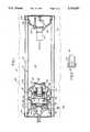
- FIG. 1illustrates a cross-sectional view of the present invention.
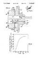
- FIG. 2illustrates an exploded view of a portion of FIG. 1.
- FIG. 3illustrates an alternate embodiment of the invention.
- FIG. 4illustrates an exploded view of a portion of FIG. 1.
- FIG. 5illustrates pressure-time profiles
- the inflator 10for inflating an air cushion such as an air bag usable within a vehicle occupant safety restraint system.
- the inflator 10comprises a pressure tank generally shown as 12.
- the pressure tankcomprises three portions including a hollow cylindrical sleeve 14 secured at one end is to a first end cap 16.
- the sleeveis also secured at end 18 to another cylindrically shaped end cap 20.
- the pressurized tank 12, in the space shown as 22,is filled and pressurized with an inert gas such as Argon. This gas may be inserted and sealed within the pressure tank through a fill tube 23 of known design.
- the pressurized gasmay also be a mixture of Argon and another inert gas such as helium.
- the amount of heliumis approximately two percent (2%) by volume of the amount of Argon gas.
- the purpose of using heliumis to provide a means for detecting defects in any of the various weld joints such as 24, 26 or 28.
- FIG. 4illustrates a typical weld joint 24. It can be seen that the sleeve 14 is spaced from the end cap 16 to permit the unrestricted migration of the stored gas to the weld joint so that any defects in such joint can be identified during the initial pressurization of the pressure tank 12. The test measures the presence of helium as known in the art.
- An optional pressure sensor 30may be secured to end cap 16.
- a sealsuch as a glass to metal seal is provided to seal an opening in the end cap 16 through which wires 34 associated with the pressure sensor are fed through.
- the end cap 20includes a necked-down portion 40 facing the interior 22 of the pressure vessel.
- the end 42 of the end cap 20is provided with an opening 44 which is closed by a rupturable, thin disk 46, preferably made of stainless steel, inconel or nickel.
- a gas generator housingSecured to an end 50 of the end cap 20 is a gas generator housing generally shown as 52. The housing 52 extends partially within the end cap 20.
- a sleeve 60Positioned within an opening 54 within the housing 52 is a sleeve 60 which includes a flange 62 adjacent the forward portion 64 of the housing 52 (see FIG. 2).
- the sleeve 60includes a narrow mouth portion 66 proximate an opening 68.
- a sliding pistonPositioned within the bore 70 formed within the sleeve 60 is a sliding piston generally shown as 72.
- the piston 72is hollow and includes at a forward end thereof a cutting edge 74.
- a burst disk 80Positioned at the rear end 76 of the piston 72 is another burst disk 80 of similar construction to burst disk 46.
- the burst disk 80encloses the hollow bore or opening 82 defined by the walls of the piston 72.
- the sliding piston 72is initially retained within the sleeve 60 by shear pins 84a and 84b.
- An alternate embodiment of the piston 72 having a pointed cutting edge 74'0is shown in FIG. 3.
- FIG. 3shows the burst disk 80 being formed as an integral part of the piston 72.
- An annular groove 78may be formed on the rear face of the disk 80 to selectively weaken same.
- the rear of the sleeve 60may be partially covered by a restraining strap 86 which may be secured such as by welding at locations 88 to the sleeve 60.
- This restraining stapmay be a thin, narrow band or alternatively, a wire.
- the purpose of the restraining strap 86will be clear from the description below. If a band is used, it is contemplated that it could be fabricated of stainless steel having a thickness of 0.050 inches (1.27 mm) and a width of approximately 0.125 inches (3.175 mm).
- a quantity of propellant material 90Positioned within the housing 52, and rearward of the sleeve 60, is a quantity of propellant material 90 (see FIG. 1) such as Arcite disclosed in U.S. Pat. No. 3,723,205, which is incorporated herein by reference.
- Arcitecan be extruded to a shape conformal with the housing 52.
- the molded propellant 90may include a plurality of axially extending passages such as 92 to control the burn rate of the propellant material 90.
- the propellant 90is supported within the propellant housing 52 by a metal retainer, 94 having a plurality of openings such as 96 coaxial with the openings 92 formed in the propellant 90.
- An initiator housing 100is secured to the propellant housing 52. Inserted within the initiator housing is an initiator or squib 102 of known variety which ignites in response to an electric control signal indicative of a crash situation. Squibs or initiators 102 or the like are well known in the art and are not described further herein.
- ignition enhancing material 110Situated upstream of the ignitor 102 and within a small cavity 108 formed in the initiator housing 100 is a small quantity of ignition enhancing material 110 which may primarily consist of boron potassium nitrate. This ignition enhancing material may be sealed within the housing 100 by encapturing same by a thin metal foil layer 112.
- the propellant 90Upon securement of the initiator housing 100 into the propellant housing 52, the propellant 90 is biased inwardly by action of a screen 104 which acts to uniformly distribute the heat, generated upon activation of the initiator 102, to the propellant 90.
- a sponge or spring element 106preferably fabricated of a silicone sponge material, provides a modest preload on the propellant to maintain same in place.
- the resilient sponge element 106includes an opening 107 so as not to interact with the flame produced by the squib 102.
- the operation of the inflator 10is as follows.
- the pressure tank 12is initially filled to a pressure of between 2,000 and 4,000 psi with Argon/helium inflation gas, however, it has been found that an inflation pressure of approximately 3,000 psi is normal for the purpose of inflating many air bags. In this condition the burst disk 46 prevents egress of the inflation gases.
- the initiator 102ignites thereby igniting the enhancing material 110 causing the propellant 90 to burn. As the propellant 90 burns, pressure is built up within the propellant housing 52 and acts on the rupture disk 80 secured to the sliding piston 72.
- This pressure which operates against the surface area of the burst disk 80will build to a sufficient magnitude to create a force adequate to shear the shear pins 84a and b causing the sliding piston 72 to move within the sleeve 60 and puncture the burst disk 46.
- the stored inflation gasimmediately exits the orifice openings 120 in the end cap 20 and flows into a manifold 130 to inflate the air bag 140 which would typically be secured about the manifold in a known manner.
- the hot products of combustion resulting from the burning propellanthave not yet mixed with the stored inflation gas and as such the puncturing of the burst disk 46 by the sliding piston 72 results in an initial, cold gas, gentle (low rate) deployment of the air bag as can be seen in the initial portions of the inflation time history as shown in FIG. 5.
- the pressure within the propellant housing 52continues to rise as a result of the burning propellant 90 until a predetermined rupture pressure of the burst disk 80 is achieved. Typically this pressure could be approximately 5,000 psi.
- the hot gases generated by the propellant 90are injected into the pressure tank 12 via the central bore 82 of the sliding piston 72.
- the injection of the hot propellant gasescauses the gases exiting the orifice openings 120 in the end portion 40 of the pressure tank 12 to be heated, resulting in an increased rate of inflation of the air bag.
- This increased rate of inflationis also shown in FIG. 5.
- FIG. 2shows the initial position of the piston 72 and also shows the stroked position of this piston (in phantom line).
- the sleeve 60includes a narrowed portion 66 which upon movement of the piston 72 causes an interference fit with the piston 72 which serves to maintain the piston in its stroked position after it has opened the rupture disk 80.
- the restraining strap 86(also shown in FIG. 2) provides a retainment for the sliding piston 72 in the event that it should stroke in reverse direction after first being exposed to the pressure of the stored Argon gas upon rupture of the burst disk 46.
- the present inventionprovides a methodology for providing the staged deployment of an air bag by selectively choosing the rupture pressure of the burst disk 80.
- the significance of thisis that the inflator 10 provides for the slow, early onset of air bag deployment which results in lower air bag deployment forces which is significant in relation to out-of-position occupants.
- any deployment doors used to enclose the air bar, in its stored conditionwould also be subjected to these lower deployment forces when they are opened, thereby providing for a more controlled opening of the deployment door.
- the rupture pressure of the burst disk 80 which permits the communication of the heated propellant gases with the stored Argon gascan be chosen so that the time between the initial soft inflation of the air bag and the more rapid inflation of the air bag due to the communication of the heated propellant gases with the stored Argon gas occurs relatively shortly thereafter.
Landscapes
- Physics & Mathematics (AREA)
- Fluid Mechanics (AREA)
- Engineering & Computer Science (AREA)
- Mechanical Engineering (AREA)
- Air Bags (AREA)
Abstract
Description
Claims (16)
Priority Applications (10)
| Application Number | Priority Date | Filing Date | Title |
|---|---|---|---|
| US07/618,428US5076607A (en) | 1990-11-27 | 1990-11-27 | Hybrid inflator |
| MX9102038AMX174031B (en) | 1990-11-27 | 1991-11-13 | HYBRID INFLATOR |
| ES92901424TES2067323T3 (en) | 1990-11-27 | 1991-11-19 | HYBRID INFLATOR. |
| KR1019930701385AKR970011515B1 (en) | 1990-11-27 | 1991-11-19 | Hybrid inflator |
| JP04501537AJP3114123B2 (en) | 1990-11-27 | 1991-11-19 | Hybrid inflator |
| DE69107093TDE69107093T2 (en) | 1990-11-27 | 1991-11-19 | HYBRID INFLATION DEVICE. |
| EP92901424AEP0558651B1 (en) | 1990-11-27 | 1991-11-19 | Hybrid inflator |
| PCT/US1991/008639WO1992009459A1 (en) | 1990-11-27 | 1991-11-19 | Hybrid inflator |
| US07/833,240US5351988A (en) | 1990-11-27 | 1992-04-14 | Hybrid inflator with staged inflation capability |
| US07/985,511US5257819A (en) | 1990-11-27 | 1992-12-02 | Hybrid inflator |
Applications Claiming Priority (1)
| Application Number | Priority Date | Filing Date | Title |
|---|---|---|---|
| US07/618,428US5076607A (en) | 1990-11-27 | 1990-11-27 | Hybrid inflator |
Related Child Applications (1)
| Application Number | Title | Priority Date | Filing Date |
|---|---|---|---|
| US80878191AContinuation-In-Part | 1990-11-27 | 1991-12-17 |
Publications (1)
| Publication Number | Publication Date |
|---|---|
| US5076607Atrue US5076607A (en) | 1991-12-31 |
Family
ID=24477625
Family Applications (1)
| Application Number | Title | Priority Date | Filing Date |
|---|---|---|---|
| US07/618,428Expired - LifetimeUS5076607A (en) | 1990-11-27 | 1990-11-27 | Hybrid inflator |
Country Status (8)
| Country | Link |
|---|---|
| US (1) | US5076607A (en) |
| EP (1) | EP0558651B1 (en) |
| JP (1) | JP3114123B2 (en) |
| KR (1) | KR970011515B1 (en) |
| DE (1) | DE69107093T2 (en) |
| ES (1) | ES2067323T3 (en) |
| MX (1) | MX174031B (en) |
| WO (1) | WO1992009459A1 (en) |
Cited By (84)
| Publication number | Priority date | Publication date | Assignee | Title |
|---|---|---|---|---|
| US5131680A (en)* | 1991-03-19 | 1992-07-21 | Trw Vehicle Safety Systems Inc. | Inflator assembly |
| US5152550A (en)* | 1991-02-05 | 1992-10-06 | Ideatech, Inc. | Air bag device for vehicles |
| WO1993011973A1 (en)* | 1991-12-17 | 1993-06-24 | Bendix-Atlantic Inflator Company | Hybrid inflator |
| US5226669A (en)* | 1991-11-07 | 1993-07-13 | Honda Giken Kogyo Kabushiki Kaisha | Gas generator for air bag system |
| US5230531A (en)* | 1990-10-22 | 1993-07-27 | Oea, Inc. | Gas generator ignition assembly using a projectile |
| WO1993021042A1 (en)* | 1992-04-14 | 1993-10-28 | Bendix-Atlantic Inflator Company | Hybrid inflator with staged inflation capability |
| US5257819A (en)* | 1990-11-27 | 1993-11-02 | Bendix Atlantic Inflator Company | Hybrid inflator |
| US5261695A (en)* | 1992-09-04 | 1993-11-16 | Ideatech, Inc. | Air bag device for vehicles |
| US5273312A (en)* | 1991-09-20 | 1993-12-28 | Trw Vehicle Safety Systems Inc. | Hybrid inflator having movable piston for releasing pressurized gas and conveying combustion products for ignition of secondary ignition material |
| US5290060A (en)* | 1992-12-14 | 1994-03-01 | Morton International, Inc. | Hybrid gas generator for air bag inflatable restraint systems |
| FR2695892A1 (en)* | 1992-09-18 | 1994-03-25 | Trw Vehicle Safety Systems | Apparatus and method for inflating an occupant restraint of a vehicle |
| DE4336356A1 (en)* | 1992-10-23 | 1994-04-28 | Trw Vehicle Safety Systems | The airbag inflator |
| DE4241221A1 (en)* | 1992-12-08 | 1994-06-09 | Dynamit Nobel Ag | Liquid gas generator for an inflatable impact protection cushion to protect a motor vehicle occupant from injuries |
| EP0604001A1 (en)* | 1992-12-24 | 1994-06-29 | Trw Vehicle Safety Systems Inc. | Inflator assembly |
| US5345876A (en)* | 1993-02-04 | 1994-09-13 | Atlantic Research Corporation | Hybrid inflator |
| US5350192A (en)* | 1993-08-11 | 1994-09-27 | Trw Vehicle Safety Systems Inc. | Inflator assembly |
| US5351989A (en)* | 1992-11-30 | 1994-10-04 | Trw Vehicle Safety Systems Inc. | Inflator assembly |
| US5362100A (en)* | 1993-10-25 | 1994-11-08 | General Motors Corporation | Control circuit for a compressed gas inflator device |
| WO1995004610A1 (en)* | 1993-08-10 | 1995-02-16 | Thiokol Corporation | Thermite compositions for use as gas generants |
| US5404263A (en)* | 1992-08-27 | 1995-04-04 | Oea, Inc. | All-glass header assembly used in an inflator system |
| US5411225A (en)* | 1993-07-26 | 1995-05-02 | Lannon; Robert G. | Reusable non-pyrotechnic countermeasure dispenser cartridge for aircraft |
| EP0652141A1 (en)* | 1993-11-09 | 1995-05-10 | Trw Inc. | Isolation member for air bag inflator |
| US5421609A (en)* | 1994-04-21 | 1995-06-06 | Morton International, Inc. | Rupture device |
| EP0658460A1 (en)* | 1993-12-13 | 1995-06-21 | Trw Vehicle Safety Systems Inc. | Apparatus and method for inflating an inflatable vehicle occupant restraint |
| US5429386A (en)* | 1993-06-07 | 1995-07-04 | Trw Vehicle Safety System Inc. | Auto ignition device for an air bag inflator |
| US5468015A (en)* | 1994-06-21 | 1995-11-21 | Trw Vehicle Safety Systems Inc. | Apparatus for inflating an inflatable vehicle occupant restraint |
| US5472229A (en)* | 1992-03-24 | 1995-12-05 | Bendix-Atlantic Inflator Company | Mounting of a thrust neutral inflator for air bag modules |
| EP0706917A1 (en) | 1994-10-12 | 1996-04-17 | Morton International, Inc. | Toroidal hybrid gas generator |
| US5513572A (en)* | 1994-05-09 | 1996-05-07 | Alliedsignal Inc. | Hybrid inflator |
| US5536040A (en)* | 1995-04-24 | 1996-07-16 | Trw Inc. | Inflator for side impact air bag |
| US5542702A (en)* | 1995-03-27 | 1996-08-06 | Morton International, Inc. | Pressurized gas inflator for vehicle occupant protection systems |
| US5551723A (en)* | 1994-07-20 | 1996-09-03 | Breed Automotive Technology, Inc. | Pulse shaping for airbag inflators |
| US5551725A (en)* | 1995-03-10 | 1996-09-03 | Ludwig; Christopher P. | Vehicle airbag inflator and related method |
| US5580085A (en)* | 1993-03-23 | 1996-12-03 | Trw Inc. | Gas augmented inflator assembly with movable closure |
| US5582426A (en)* | 1995-10-24 | 1996-12-10 | Trw Vehicle Safety Systems Inc. | Vented ignition cup in stored fluid inflator |
| US5584505A (en)* | 1993-08-20 | 1996-12-17 | Trw Inc. | Inflator assembly |
| US5584504A (en)* | 1995-03-24 | 1996-12-17 | Trw Inc. | Inflator assembly |
| US5586783A (en)* | 1994-02-24 | 1996-12-24 | Temic Bayern-Chemie Airbag Gmbh | Hybrid gas generator for filling a gas bag |
| US5590905A (en)* | 1994-12-06 | 1997-01-07 | Trw Inc. | Air bag inflator |
| US5593180A (en)* | 1995-04-24 | 1997-01-14 | Trw Inc. | Dual chamber inflator for side impact air bag |
| US5601310A (en)* | 1995-09-19 | 1997-02-11 | Atlantic Research Corporation | Hybrid inflator and method of use |
| US5611567A (en)* | 1995-12-18 | 1997-03-18 | Cartridge Actuated Devices, Inc. | Non-explosive linear release device |
| US5620204A (en)* | 1996-01-05 | 1997-04-15 | Trw Vehicle Safety Systems Inc. | Apparatus for inflating an inflatable vehicle occupant protection device |
| US5632505A (en)* | 1995-06-29 | 1997-05-27 | Trw Vehicle Safety Systems Inc. | Pressure vessel with rupturable closure wall |
| US5647924A (en)* | 1993-10-20 | 1997-07-15 | Quantic Industries, Inc. | Electrical initiator |
| US5648634A (en)* | 1993-10-20 | 1997-07-15 | Quantic Industries, Inc. | Electrical initiator |
| US5659295A (en)* | 1995-12-11 | 1997-08-19 | Bendix-Atlantic Inflator Company | Sliding piston pressure sensing device |
| US5695215A (en)* | 1996-04-24 | 1997-12-09 | Trw Inc. | Fill tube for air bag inflator |
| US5709724A (en)* | 1994-08-04 | 1998-01-20 | Coors Ceramics Company | Process for fabricating a hermetic glass-to-metal seal |
| US5709406A (en)* | 1996-02-28 | 1998-01-20 | Morton International, Inc. | Hybrid inflator with projectile gas release |
| US5863066A (en)* | 1997-03-13 | 1999-01-26 | Trw Vehicle Safety Systems Inc. | Multiple stage air bag inflator |
| US5884938A (en)* | 1996-04-15 | 1999-03-23 | Autoliv Asp Inc. | Pressurized fluid containing airbag inflator |
| US5941562A (en)* | 1996-04-15 | 1999-08-24 | Autoliv Asp | Adaptive output inflator having a selectable oxidant composition |
| US5979935A (en)* | 1997-12-05 | 1999-11-09 | Trw Inc. | Apparatus and method for sensing gas pressure inside an inflator |
| US5993230A (en)* | 1996-08-12 | 1999-11-30 | Thomas & Betts International, Inc. | Orientationless squib connector assembly for automotive air bag assemblies |
| US6010153A (en)* | 1997-02-21 | 2000-01-04 | Breed Automotive Technology, Inc. | Hybrid inflator for airbags |
| US6142518A (en)* | 1997-12-05 | 2000-11-07 | Oea, Inc. | Dual inflator apparatus including pyrotechnic inflator |
| US6189922B1 (en) | 1998-09-21 | 2001-02-20 | Autoliv Asp Inc. | Inflator with multiple initiators |
| US6233908B1 (en) | 1998-12-24 | 2001-05-22 | Autoliv Asp, Inc. | Method of introducing a leak trace material into an airbag inflator |
| US6244623B1 (en) | 2000-02-02 | 2001-06-12 | Autoliv Asp, Inc. | Flow-open inflator |
| US6274252B1 (en)* | 1994-08-04 | 2001-08-14 | Coors Ceramics Company | Hermetic glass-to-metal seal useful in headers for airbags |
| US6276953B1 (en) | 1997-12-04 | 2001-08-21 | Thoma & Betts International, Inc. | Orientationless squib connector assembly for automotive air bag assemblies |
| US6289814B1 (en) | 1996-04-15 | 2001-09-18 | Autoliv Asp, Inc. | Heat source for airbag inflation gas generation via a dissociating material |
| US6332404B1 (en) | 1996-04-15 | 2001-12-25 | Autoliv Asp, Inc. | Airbag inflation gas generation via a dissociating material and the moderation thereof |
| US6418870B1 (en) | 2000-05-31 | 2002-07-16 | Systems Engineering Associates Corporation | Torpedo launch mechanism and method |
| US20020093182A1 (en)* | 2001-01-15 | 2002-07-18 | Hideki Mizuno | Inflator |
| USRE37843E1 (en) | 1991-09-18 | 2002-09-17 | Trw Vehicle Safety Systems Inc. | Apparatus for inflating a vehicle occupant restraint using a mixture of gases |
| US6499646B1 (en)* | 2000-04-05 | 2002-12-31 | Indian Sugar And General Engineering Corp. | Fusion welded liquefiable gas cylinder with overpressure protection heads and method for making the same |
| US6543806B1 (en) | 2000-08-03 | 2003-04-08 | Nxgen Technologies Llc | Inflator for vehicle protection apparatus |
| US20030151241A1 (en)* | 2001-11-30 | 2003-08-14 | Naoki Matsuda | Inflator |
| US6634302B1 (en) | 2000-02-02 | 2003-10-21 | Autoliv Asp, Inc. | Airbag inflation gas generation |
| US20050016412A1 (en)* | 2003-02-10 | 2005-01-27 | Pepperball Technologies, Inc., A Delaware Corporation | Stabilized non-lethal projectile systems |
| US6883830B2 (en) | 2001-09-27 | 2005-04-26 | Daicel Chemical Industries, Ltd. | Pressurized medium for inflator |
| US20050188886A1 (en)* | 1996-11-18 | 2005-09-01 | Pepperball Technologies, Inc. | Non-lethal projectile systems |
| US6959649B2 (en) | 2000-12-27 | 2005-11-01 | Daicel Chemical Industries, Ltd. | Inflator |
| US20060027223A1 (en)* | 2004-05-12 | 2006-02-09 | Pepperball Technologies, Inc. | Compact projectile launcher |
| US20060086408A1 (en)* | 2004-10-26 | 2006-04-27 | Trw Airbag Systems Gmbh | Gas generator |
| US20060103124A1 (en)* | 2002-08-20 | 2006-05-18 | Thomas Marotzke | Airbag module having a gas generator |
| US20060290108A1 (en)* | 2005-06-23 | 2006-12-28 | Trw Vehicle Safety Systems Inc. | Heated gas inflator |
| US20070245919A1 (en)* | 1996-11-18 | 2007-10-25 | Pepperball Technologies, Inc. | Non-lethal projectiles for delivering an inhibiting substance to a living target |
| US20080017179A1 (en)* | 2004-05-12 | 2008-01-24 | Pepperball Technologies, Inc. | Compressed Gas Cartridge Puncture Apparatus |
| US7752974B2 (en) | 2007-09-18 | 2010-07-13 | Pepperball Technologies, Inc. | Systems, methods and apparatus for use in distributing irritant powder |
| US8439301B1 (en) | 2011-07-18 | 2013-05-14 | Systems Engineering Associates Corporation | Systems and methods for deployment and operation of unmanned aerial vehicles |
| CN106660511A (en)* | 2014-07-10 | 2017-05-10 | 关键安全体系股份有限公司 | Igniter assembly with retractable piston |
Citations (25)
| Publication number | Priority date | Publication date | Assignee | Title |
|---|---|---|---|---|
| US3663036A (en)* | 1970-06-16 | 1972-05-16 | Olin Corp | Vehicle safety device having an inflatable confinement |
| US3690695A (en)* | 1970-08-14 | 1972-09-12 | Jones Sr John L | Personnel restraint system for vehicular occupants |
| US3723205A (en)* | 1971-05-07 | 1973-03-27 | Susquehanna Corp | Gas generating composition with polyvinyl chloride binder |
| US3741580A (en)* | 1971-08-27 | 1973-06-26 | Gen Motors Corp | Occupant restraint system |
| US3756621A (en)* | 1971-11-03 | 1973-09-04 | Allied Chem | Argon compressed gas supply |
| US3773353A (en)* | 1972-09-05 | 1973-11-20 | Olin Corp | Inflating device for use with vehicle safety systems |
| US3774807A (en)* | 1971-06-08 | 1973-11-27 | Ici America Inc | Gas-generating valve |
| US3883156A (en)* | 1974-02-01 | 1975-05-13 | Wallace N Frazier | Bumper-actuated trigger mechanism for vehicle safety crash bag |
| US3895821A (en)* | 1973-06-01 | 1975-07-22 | Allied Chem | Inflation apparatus for safety device |
| US3910596A (en)* | 1973-06-01 | 1975-10-07 | Allied Chem | Inflation apparatus for safety device |
| USRE28624E (en)* | 1971-11-03 | 1975-11-25 | Argon compressed gas supply | |
| US3948540A (en)* | 1972-08-04 | 1976-04-06 | Eaton Corporation | Controlled flow fluid supply for occupant restraint systems |
| US3966226A (en)* | 1972-04-17 | 1976-06-29 | Eaton Corporation | Fluid supply for occupant restraint system |
| US3972545A (en)* | 1975-03-10 | 1976-08-03 | Thiokol Corporation | Multi-level cool gas generator |
| US4006919A (en)* | 1974-05-16 | 1977-02-08 | Eaton Corporation | Inflator assembly and flow control valve for same |
| US4007685A (en)* | 1975-07-30 | 1977-02-15 | The United States Of America As Represented By The Secretary Of The Army | Gas generator |
| US4018457A (en)* | 1972-09-05 | 1977-04-19 | Olin Corporation | Inflating device for use with vehicle safety systems |
| US4021058A (en)* | 1974-10-30 | 1977-05-03 | Nippon Soken, Inc. | Safety bag device for vehicle |
| US4136894A (en)* | 1976-07-29 | 1979-01-30 | Daicel Ltd. | Gas generator for inflatable vehicle safety bags |
| US4203616A (en)* | 1977-02-08 | 1980-05-20 | Honda Giken Kogyo Kabushiki Kaisha | Air bag device for cars |
| US4268065A (en)* | 1977-07-04 | 1981-05-19 | Hubert Granig | Device for discharging pressure gas reservoirs |
| US4358998A (en)* | 1980-02-04 | 1982-11-16 | Thiokol Corporation | Igniter for a pyrotechnic gas bag inflator |
| US4619285A (en)* | 1983-06-10 | 1986-10-28 | Futurecraft Corporation | Fluid flow control device |
| US4771914A (en)* | 1986-10-22 | 1988-09-20 | Koichi Kaneda | Air bag triggering device |
| US5022674A (en)* | 1990-04-05 | 1991-06-11 | Bendix Atlantic Inflator Company | Dual pyrotechnic hybrid inflator |
- 1990
- 1990-11-27USUS07/618,428patent/US5076607A/ennot_activeExpired - Lifetime
- 1991
- 1991-11-13MXMX9102038Apatent/MX174031B/enunknown
- 1991-11-19EPEP92901424Apatent/EP0558651B1/ennot_activeExpired - Lifetime
- 1991-11-19DEDE69107093Tpatent/DE69107093T2/ennot_activeExpired - Fee Related
- 1991-11-19KRKR1019930701385Apatent/KR970011515B1/ennot_activeExpired - Fee Related
- 1991-11-19JPJP04501537Apatent/JP3114123B2/ennot_activeExpired - Fee Related
- 1991-11-19ESES92901424Tpatent/ES2067323T3/ennot_activeExpired - Lifetime
- 1991-11-19WOPCT/US1991/008639patent/WO1992009459A1/enactiveIP Right Grant
Patent Citations (25)
| Publication number | Priority date | Publication date | Assignee | Title |
|---|---|---|---|---|
| US3663036A (en)* | 1970-06-16 | 1972-05-16 | Olin Corp | Vehicle safety device having an inflatable confinement |
| US3690695A (en)* | 1970-08-14 | 1972-09-12 | Jones Sr John L | Personnel restraint system for vehicular occupants |
| US3723205A (en)* | 1971-05-07 | 1973-03-27 | Susquehanna Corp | Gas generating composition with polyvinyl chloride binder |
| US3774807A (en)* | 1971-06-08 | 1973-11-27 | Ici America Inc | Gas-generating valve |
| US3741580A (en)* | 1971-08-27 | 1973-06-26 | Gen Motors Corp | Occupant restraint system |
| USRE28624E (en)* | 1971-11-03 | 1975-11-25 | Argon compressed gas supply | |
| US3756621A (en)* | 1971-11-03 | 1973-09-04 | Allied Chem | Argon compressed gas supply |
| US3966226A (en)* | 1972-04-17 | 1976-06-29 | Eaton Corporation | Fluid supply for occupant restraint system |
| US3948540A (en)* | 1972-08-04 | 1976-04-06 | Eaton Corporation | Controlled flow fluid supply for occupant restraint systems |
| US4018457A (en)* | 1972-09-05 | 1977-04-19 | Olin Corporation | Inflating device for use with vehicle safety systems |
| US3773353A (en)* | 1972-09-05 | 1973-11-20 | Olin Corp | Inflating device for use with vehicle safety systems |
| US3895821A (en)* | 1973-06-01 | 1975-07-22 | Allied Chem | Inflation apparatus for safety device |
| US3910596A (en)* | 1973-06-01 | 1975-10-07 | Allied Chem | Inflation apparatus for safety device |
| US3883156A (en)* | 1974-02-01 | 1975-05-13 | Wallace N Frazier | Bumper-actuated trigger mechanism for vehicle safety crash bag |
| US4006919A (en)* | 1974-05-16 | 1977-02-08 | Eaton Corporation | Inflator assembly and flow control valve for same |
| US4021058A (en)* | 1974-10-30 | 1977-05-03 | Nippon Soken, Inc. | Safety bag device for vehicle |
| US3972545A (en)* | 1975-03-10 | 1976-08-03 | Thiokol Corporation | Multi-level cool gas generator |
| US4007685A (en)* | 1975-07-30 | 1977-02-15 | The United States Of America As Represented By The Secretary Of The Army | Gas generator |
| US4136894A (en)* | 1976-07-29 | 1979-01-30 | Daicel Ltd. | Gas generator for inflatable vehicle safety bags |
| US4203616A (en)* | 1977-02-08 | 1980-05-20 | Honda Giken Kogyo Kabushiki Kaisha | Air bag device for cars |
| US4268065A (en)* | 1977-07-04 | 1981-05-19 | Hubert Granig | Device for discharging pressure gas reservoirs |
| US4358998A (en)* | 1980-02-04 | 1982-11-16 | Thiokol Corporation | Igniter for a pyrotechnic gas bag inflator |
| US4619285A (en)* | 1983-06-10 | 1986-10-28 | Futurecraft Corporation | Fluid flow control device |
| US4771914A (en)* | 1986-10-22 | 1988-09-20 | Koichi Kaneda | Air bag triggering device |
| US5022674A (en)* | 1990-04-05 | 1991-06-11 | Bendix Atlantic Inflator Company | Dual pyrotechnic hybrid inflator |
Cited By (106)
| Publication number | Priority date | Publication date | Assignee | Title |
|---|---|---|---|---|
| US5230531A (en)* | 1990-10-22 | 1993-07-27 | Oea, Inc. | Gas generator ignition assembly using a projectile |
| US5257819A (en)* | 1990-11-27 | 1993-11-02 | Bendix Atlantic Inflator Company | Hybrid inflator |
| US5351988A (en)* | 1990-11-27 | 1994-10-04 | Alliedsignal Inc. | Hybrid inflator with staged inflation capability |
| US5152550A (en)* | 1991-02-05 | 1992-10-06 | Ideatech, Inc. | Air bag device for vehicles |
| US5131680A (en)* | 1991-03-19 | 1992-07-21 | Trw Vehicle Safety Systems Inc. | Inflator assembly |
| WO1993002894A1 (en)* | 1991-08-07 | 1993-02-18 | Ideatech, Inc. | Air bag device for vehicles |
| USRE37843E1 (en) | 1991-09-18 | 2002-09-17 | Trw Vehicle Safety Systems Inc. | Apparatus for inflating a vehicle occupant restraint using a mixture of gases |
| US5348344A (en)* | 1991-09-18 | 1994-09-20 | Trw Vehicle Safety Systems Inc. | Apparatus for inflating a vehicle occupant restraint using a mixture of gases |
| US5273312A (en)* | 1991-09-20 | 1993-12-28 | Trw Vehicle Safety Systems Inc. | Hybrid inflator having movable piston for releasing pressurized gas and conveying combustion products for ignition of secondary ignition material |
| US5226669A (en)* | 1991-11-07 | 1993-07-13 | Honda Giken Kogyo Kabushiki Kaisha | Gas generator for air bag system |
| WO1993011973A1 (en)* | 1991-12-17 | 1993-06-24 | Bendix-Atlantic Inflator Company | Hybrid inflator |
| US5472229A (en)* | 1992-03-24 | 1995-12-05 | Bendix-Atlantic Inflator Company | Mounting of a thrust neutral inflator for air bag modules |
| WO1993021042A1 (en)* | 1992-04-14 | 1993-10-28 | Bendix-Atlantic Inflator Company | Hybrid inflator with staged inflation capability |
| JP3259229B2 (en) | 1992-04-14 | 2002-02-25 | アトランティック・リサーチ・コーポレーション | Inflator |
| US5404263A (en)* | 1992-08-27 | 1995-04-04 | Oea, Inc. | All-glass header assembly used in an inflator system |
| US5261695A (en)* | 1992-09-04 | 1993-11-16 | Ideatech, Inc. | Air bag device for vehicles |
| FR2695892A1 (en)* | 1992-09-18 | 1994-03-25 | Trw Vehicle Safety Systems | Apparatus and method for inflating an occupant restraint of a vehicle |
| DE4336356A1 (en)* | 1992-10-23 | 1994-04-28 | Trw Vehicle Safety Systems | The airbag inflator |
| DE4336356C2 (en)* | 1992-10-23 | 1999-01-07 | Trw Vehicle Safety Systems | Airbag inflator |
| US5351989A (en)* | 1992-11-30 | 1994-10-04 | Trw Vehicle Safety Systems Inc. | Inflator assembly |
| DE4241221A1 (en)* | 1992-12-08 | 1994-06-09 | Dynamit Nobel Ag | Liquid gas generator for an inflatable impact protection cushion to protect a motor vehicle occupant from injuries |
| US5290060A (en)* | 1992-12-14 | 1994-03-01 | Morton International, Inc. | Hybrid gas generator for air bag inflatable restraint systems |
| EP0604001A1 (en)* | 1992-12-24 | 1994-06-29 | Trw Vehicle Safety Systems Inc. | Inflator assembly |
| US5345876A (en)* | 1993-02-04 | 1994-09-13 | Atlantic Research Corporation | Hybrid inflator |
| US5580085A (en)* | 1993-03-23 | 1996-12-03 | Trw Inc. | Gas augmented inflator assembly with movable closure |
| US5429386A (en)* | 1993-06-07 | 1995-07-04 | Trw Vehicle Safety System Inc. | Auto ignition device for an air bag inflator |
| US5411225A (en)* | 1993-07-26 | 1995-05-02 | Lannon; Robert G. | Reusable non-pyrotechnic countermeasure dispenser cartridge for aircraft |
| WO1995004610A1 (en)* | 1993-08-10 | 1995-02-16 | Thiokol Corporation | Thermite compositions for use as gas generants |
| US5350192A (en)* | 1993-08-11 | 1994-09-27 | Trw Vehicle Safety Systems Inc. | Inflator assembly |
| US5584505A (en)* | 1993-08-20 | 1996-12-17 | Trw Inc. | Inflator assembly |
| US5648634A (en)* | 1993-10-20 | 1997-07-15 | Quantic Industries, Inc. | Electrical initiator |
| US5763814A (en)* | 1993-10-20 | 1998-06-09 | Quanti Industries, Inc. | Electrical initiator |
| US5647924A (en)* | 1993-10-20 | 1997-07-15 | Quantic Industries, Inc. | Electrical initiator |
| US5711531A (en)* | 1993-10-20 | 1998-01-27 | Quantic Industries, Inc. | Electrical initiator seal |
| US5728964A (en)* | 1993-10-20 | 1998-03-17 | Quantic Industries, Inc. | Electrical initiator |
| US5362100A (en)* | 1993-10-25 | 1994-11-08 | General Motors Corporation | Control circuit for a compressed gas inflator device |
| EP0652141A1 (en)* | 1993-11-09 | 1995-05-10 | Trw Inc. | Isolation member for air bag inflator |
| US5454592A (en)* | 1993-12-13 | 1995-10-03 | Trw Vehicle Safety Systems Inc. | Apparatus and method for inflating an inflatable vehicle occupant restraint |
| EP0658460A1 (en)* | 1993-12-13 | 1995-06-21 | Trw Vehicle Safety Systems Inc. | Apparatus and method for inflating an inflatable vehicle occupant restraint |
| US5586783A (en)* | 1994-02-24 | 1996-12-24 | Temic Bayern-Chemie Airbag Gmbh | Hybrid gas generator for filling a gas bag |
| US5421609A (en)* | 1994-04-21 | 1995-06-06 | Morton International, Inc. | Rupture device |
| US5513572A (en)* | 1994-05-09 | 1996-05-07 | Alliedsignal Inc. | Hybrid inflator |
| US5468015A (en)* | 1994-06-21 | 1995-11-21 | Trw Vehicle Safety Systems Inc. | Apparatus for inflating an inflatable vehicle occupant restraint |
| US5551723A (en)* | 1994-07-20 | 1996-09-03 | Breed Automotive Technology, Inc. | Pulse shaping for airbag inflators |
| US6274252B1 (en)* | 1994-08-04 | 2001-08-14 | Coors Ceramics Company | Hermetic glass-to-metal seal useful in headers for airbags |
| US5709724A (en)* | 1994-08-04 | 1998-01-20 | Coors Ceramics Company | Process for fabricating a hermetic glass-to-metal seal |
| JPH08175313A (en)* | 1994-10-12 | 1996-07-09 | Morton Internatl Inc | Hybrid inflator and hybrid inflator for vehicle occupant restraint system |
| EP0706917A1 (en) | 1994-10-12 | 1996-04-17 | Morton International, Inc. | Toroidal hybrid gas generator |
| US5590905A (en)* | 1994-12-06 | 1997-01-07 | Trw Inc. | Air bag inflator |
| US5551725A (en)* | 1995-03-10 | 1996-09-03 | Ludwig; Christopher P. | Vehicle airbag inflator and related method |
| US5584504A (en)* | 1995-03-24 | 1996-12-17 | Trw Inc. | Inflator assembly |
| US5542702A (en)* | 1995-03-27 | 1996-08-06 | Morton International, Inc. | Pressurized gas inflator for vehicle occupant protection systems |
| US5593180A (en)* | 1995-04-24 | 1997-01-14 | Trw Inc. | Dual chamber inflator for side impact air bag |
| US5536040A (en)* | 1995-04-24 | 1996-07-16 | Trw Inc. | Inflator for side impact air bag |
| US5632505A (en)* | 1995-06-29 | 1997-05-27 | Trw Vehicle Safety Systems Inc. | Pressure vessel with rupturable closure wall |
| US5601310A (en)* | 1995-09-19 | 1997-02-11 | Atlantic Research Corporation | Hybrid inflator and method of use |
| US5582426A (en)* | 1995-10-24 | 1996-12-10 | Trw Vehicle Safety Systems Inc. | Vented ignition cup in stored fluid inflator |
| US5659295A (en)* | 1995-12-11 | 1997-08-19 | Bendix-Atlantic Inflator Company | Sliding piston pressure sensing device |
| US5611567A (en)* | 1995-12-18 | 1997-03-18 | Cartridge Actuated Devices, Inc. | Non-explosive linear release device |
| US5620204A (en)* | 1996-01-05 | 1997-04-15 | Trw Vehicle Safety Systems Inc. | Apparatus for inflating an inflatable vehicle occupant protection device |
| US5709406A (en)* | 1996-02-28 | 1998-01-20 | Morton International, Inc. | Hybrid inflator with projectile gas release |
| US5884938A (en)* | 1996-04-15 | 1999-03-23 | Autoliv Asp Inc. | Pressurized fluid containing airbag inflator |
| US5941562A (en)* | 1996-04-15 | 1999-08-24 | Autoliv Asp | Adaptive output inflator having a selectable oxidant composition |
| US6332404B1 (en) | 1996-04-15 | 2001-12-25 | Autoliv Asp, Inc. | Airbag inflation gas generation via a dissociating material and the moderation thereof |
| US6289814B1 (en) | 1996-04-15 | 2001-09-18 | Autoliv Asp, Inc. | Heat source for airbag inflation gas generation via a dissociating material |
| US5695215A (en)* | 1996-04-24 | 1997-12-09 | Trw Inc. | Fill tube for air bag inflator |
| US5993230A (en)* | 1996-08-12 | 1999-11-30 | Thomas & Betts International, Inc. | Orientationless squib connector assembly for automotive air bag assemblies |
| US6203342B1 (en) | 1996-08-12 | 2001-03-20 | Thomas & Betts International, Inc. | Grounding plate for orientationless squib connector assembly for automotive air bag assemblies |
| US20070245919A1 (en)* | 1996-11-18 | 2007-10-25 | Pepperball Technologies, Inc. | Non-lethal projectiles for delivering an inhibiting substance to a living target |
| US20050188886A1 (en)* | 1996-11-18 | 2005-09-01 | Pepperball Technologies, Inc. | Non-lethal projectile systems |
| US6010153A (en)* | 1997-02-21 | 2000-01-04 | Breed Automotive Technology, Inc. | Hybrid inflator for airbags |
| US5863066A (en)* | 1997-03-13 | 1999-01-26 | Trw Vehicle Safety Systems Inc. | Multiple stage air bag inflator |
| US6276953B1 (en) | 1997-12-04 | 2001-08-21 | Thoma & Betts International, Inc. | Orientationless squib connector assembly for automotive air bag assemblies |
| US6142518A (en)* | 1997-12-05 | 2000-11-07 | Oea, Inc. | Dual inflator apparatus including pyrotechnic inflator |
| US5979935A (en)* | 1997-12-05 | 1999-11-09 | Trw Inc. | Apparatus and method for sensing gas pressure inside an inflator |
| US6189922B1 (en) | 1998-09-21 | 2001-02-20 | Autoliv Asp Inc. | Inflator with multiple initiators |
| US6233908B1 (en) | 1998-12-24 | 2001-05-22 | Autoliv Asp, Inc. | Method of introducing a leak trace material into an airbag inflator |
| US6634302B1 (en) | 2000-02-02 | 2003-10-21 | Autoliv Asp, Inc. | Airbag inflation gas generation |
| US6244623B1 (en) | 2000-02-02 | 2001-06-12 | Autoliv Asp, Inc. | Flow-open inflator |
| US6499646B1 (en)* | 2000-04-05 | 2002-12-31 | Indian Sugar And General Engineering Corp. | Fusion welded liquefiable gas cylinder with overpressure protection heads and method for making the same |
| US6418870B1 (en) | 2000-05-31 | 2002-07-16 | Systems Engineering Associates Corporation | Torpedo launch mechanism and method |
| US6543806B1 (en) | 2000-08-03 | 2003-04-08 | Nxgen Technologies Llc | Inflator for vehicle protection apparatus |
| EP1346885A4 (en)* | 2000-12-27 | 2007-03-21 | Daicel Chem | inflation |
| US6959649B2 (en) | 2000-12-27 | 2005-11-01 | Daicel Chemical Industries, Ltd. | Inflator |
| US7290796B2 (en) | 2000-12-27 | 2007-11-06 | Daicel Chemical Industries, Ltd. | Inflator |
| US20050242556A1 (en)* | 2000-12-27 | 2005-11-03 | Daicel Chemical Industries, Ltd. | Inflator |
| US20020093182A1 (en)* | 2001-01-15 | 2002-07-18 | Hideki Mizuno | Inflator |
| EP1223085A3 (en)* | 2001-01-15 | 2004-05-26 | Takata Corporation | Inflator |
| US6834885B2 (en) | 2001-01-15 | 2004-12-28 | Takata Corporation | Inflator |
| US6883830B2 (en) | 2001-09-27 | 2005-04-26 | Daicel Chemical Industries, Ltd. | Pressurized medium for inflator |
| US7134689B2 (en)* | 2001-11-30 | 2006-11-14 | Daicel Chemical Industries, Ltd. | Inflator |
| US20030151241A1 (en)* | 2001-11-30 | 2003-08-14 | Naoki Matsuda | Inflator |
| US20060103124A1 (en)* | 2002-08-20 | 2006-05-18 | Thomas Marotzke | Airbag module having a gas generator |
| US7526998B2 (en) | 2003-02-10 | 2009-05-05 | Pepperball Technologies, Inc. | Stabilized non-lethal projectile systems |
| US20050016412A1 (en)* | 2003-02-10 | 2005-01-27 | Pepperball Technologies, Inc., A Delaware Corporation | Stabilized non-lethal projectile systems |
| US20060027223A1 (en)* | 2004-05-12 | 2006-02-09 | Pepperball Technologies, Inc. | Compact projectile launcher |
| US20080017179A1 (en)* | 2004-05-12 | 2008-01-24 | Pepperball Technologies, Inc. | Compressed Gas Cartridge Puncture Apparatus |
| US20060086408A1 (en)* | 2004-10-26 | 2006-04-27 | Trw Airbag Systems Gmbh | Gas generator |
| US7641231B2 (en)* | 2004-10-26 | 2010-01-05 | Trw Airbag Systems Gmbh | Gas generator |
| US20060290108A1 (en)* | 2005-06-23 | 2006-12-28 | Trw Vehicle Safety Systems Inc. | Heated gas inflator |
| US7380820B2 (en) | 2005-06-23 | 2008-06-03 | Trw Vehicle Safety Systems Inc. | Heated gas inflator |
| US7752974B2 (en) | 2007-09-18 | 2010-07-13 | Pepperball Technologies, Inc. | Systems, methods and apparatus for use in distributing irritant powder |
| US8439301B1 (en) | 2011-07-18 | 2013-05-14 | Systems Engineering Associates Corporation | Systems and methods for deployment and operation of unmanned aerial vehicles |
| CN106660511A (en)* | 2014-07-10 | 2017-05-10 | 关键安全体系股份有限公司 | Igniter assembly with retractable piston |
| US10017149B2 (en) | 2014-07-10 | 2018-07-10 | Key Safety Systems, Inc. | Igniter assembly with retractable piston |
| CN106660511B (en)* | 2014-07-10 | 2020-03-27 | 关键安全体系股份有限公司 | Igniter assembly with retractable piston |
Also Published As
| Publication number | Publication date |
|---|---|
| DE69107093D1 (en) | 1995-03-09 |
| KR930702178A (en) | 1993-09-08 |
| JP3114123B2 (en) | 2000-12-04 |
| DE69107093T2 (en) | 1995-09-14 |
| MX9102038A (en) | 1994-01-31 |
| MX174031B (en) | 1994-04-12 |
| ES2067323T3 (en) | 1995-03-16 |
| KR970011515B1 (en) | 1997-07-11 |
| EP0558651A1 (en) | 1993-09-08 |
| JPH06503288A (en) | 1994-04-14 |
| WO1992009459A1 (en) | 1992-06-11 |
| EP0558651B1 (en) | 1995-01-25 |
Similar Documents
| Publication | Publication Date | Title |
|---|---|---|
| US5076607A (en) | Hybrid inflator | |
| US5257819A (en) | Hybrid inflator | |
| US5345876A (en) | Hybrid inflator | |
| US5351988A (en) | Hybrid inflator with staged inflation capability | |
| US5078422A (en) | Gas inflator apparatus | |
| US6106008A (en) | Hybrid airbag inflator | |
| US5931495A (en) | Ignition system for a fluid-fueled inflator | |
| US3868124A (en) | Inflating device for use with vehicle safety systems | |
| US6199905B1 (en) | High thermal efficiency inflator and passive restraints incorporating same | |
| US6857657B2 (en) | Inflator having a support member capable of sliding to open the pressure vessel | |
| EP0616578B1 (en) | Hybrid inflator | |
| US7004500B2 (en) | Dual stage inflator with extended gas delivery for a vehicular airbag system | |
| US6820898B2 (en) | Biaxial dual stage inflator with extended gas delivery for a vehicular airbag system | |
| US6155600A (en) | Safety air bag inflation device | |
| US3966224A (en) | Multiple inflation rate occupant restraint system | |
| EP1631480B1 (en) | Multiple stage inflator | |
| JP2005520734A (en) | Dual-flow inflator for vehicle airbag systems | |
| US6296274B1 (en) | Apparatus for inflating a side curtain | |
| US5880534A (en) | Sequencing system for variable level output inflators |
Legal Events
| Date | Code | Title | Description |
|---|---|---|---|
| AS | Assignment | Owner name:BENDIX-ATLANTIC INFLATOR COMPANY, 1755 MAPLELAWN D Free format text:ASSIGNMENT OF ASSIGNORS INTEREST.;ASSIGNORS:WOODS, CHARLES D.;RENFROE, DONALD W.;ROSE, JAMES M.;AND OTHERS;REEL/FRAME:005621/0450;SIGNING DATES FROM 19910102 TO 19910130 Owner name:BENDIX-ATLANTIC INFLATOR COMPANY, 1755 MAPLELAWN D Free format text:ASSIGNMENT OF ASSIGNORS INTEREST.;ASSIGNORS:FRANTOM, RICHARD L.;BISHOP, ROBERT J.;KREMER, ROBERT M.;AND OTHERS;REEL/FRAME:005621/0453;SIGNING DATES FROM 19900212 TO 19900217 | |
| STCF | Information on status: patent grant | Free format text:PATENTED CASE | |
| FPAY | Fee payment | Year of fee payment:4 | |
| FEPP | Fee payment procedure | Free format text:PAYOR NUMBER ASSIGNED (ORIGINAL EVENT CODE: ASPN); ENTITY STATUS OF PATENT OWNER: LARGE ENTITY | |
| FPAY | Fee payment | Year of fee payment:8 | |
| FPAY | Fee payment | Year of fee payment:12 | |
| AS | Assignment | Owner name:LEHMAN COMMERCIAL PAPER, INC., NEW YORK Free format text:GUARANTEE AND COLLATERAL AGREEMENT;ASSIGNOR:ATLANTIC RESEARCH CORPORATION;REEL/FRAME:020525/0682 Effective date:20071203 | |
| AS | Assignment | Owner name:BARCLAYS BANK PLC, NEW YORK Free format text:ASSIGNMENT OF SECURITY INTEREST;ASSIGNOR:LEHMAN COMMERCIAL PAPER INC.;REEL/FRAME:027068/0254 Effective date:20111014 |