US5076526A - Fastener for bicycle accessories - Google Patents
Fastener for bicycle accessoriesDownload PDFInfo
- Publication number
- US5076526A US5076526AUS07/490,731US49073190AUS5076526AUS 5076526 AUS5076526 AUS 5076526AUS 49073190 AUS49073190 AUS 49073190AUS 5076526 AUS5076526 AUS 5076526A
- Authority
- US
- United States
- Prior art keywords
- fastener
- opening
- pair
- retainer portions
- medial portion
- Prior art date
- Legal status (The legal status is an assumption and is not a legal conclusion. Google has not performed a legal analysis and makes no representation as to the accuracy of the status listed.)
- Expired - Fee Related
Links
Images


Classifications
- B—PERFORMING OPERATIONS; TRANSPORTING
- B62—LAND VEHICLES FOR TRAVELLING OTHERWISE THAN ON RAILS
- B62H—CYCLE STANDS; SUPPORTS OR HOLDERS FOR PARKING OR STORING CYCLES; APPLIANCES PREVENTING OR INDICATING UNAUTHORIZED USE OR THEFT OF CYCLES; LOCKS INTEGRAL WITH CYCLES; DEVICES FOR LEARNING TO RIDE CYCLES
- B62H5/00—Appliances preventing or indicating unauthorised use or theft of cycles; Locks integral with cycles
- B—PERFORMING OPERATIONS; TRANSPORTING
- B62—LAND VEHICLES FOR TRAVELLING OTHERWISE THAN ON RAILS
- B62J—CYCLE SADDLES OR SEATS; AUXILIARY DEVICES OR ACCESSORIES SPECIALLY ADAPTED TO CYCLES AND NOT OTHERWISE PROVIDED FOR, e.g. ARTICLE CARRIERS OR CYCLE PROTECTORS
- B62J11/00—Supporting arrangements specially adapted for fastening specific devices to cycles, e.g. supports for attaching maps
- B62J11/04—Supporting arrangements specially adapted for fastening specific devices to cycles, e.g. supports for attaching maps for bottles
- B—PERFORMING OPERATIONS; TRANSPORTING
- B62—LAND VEHICLES FOR TRAVELLING OTHERWISE THAN ON RAILS
- B62H—CYCLE STANDS; SUPPORTS OR HOLDERS FOR PARKING OR STORING CYCLES; APPLIANCES PREVENTING OR INDICATING UNAUTHORIZED USE OR THEFT OF CYCLES; LOCKS INTEGRAL WITH CYCLES; DEVICES FOR LEARNING TO RIDE CYCLES
- B62H5/00—Appliances preventing or indicating unauthorised use or theft of cycles; Locks integral with cycles
- B62H2005/008—Arrangements or adaptations for supporting U-locks on cycles
- Y—GENERAL TAGGING OF NEW TECHNOLOGICAL DEVELOPMENTS; GENERAL TAGGING OF CROSS-SECTIONAL TECHNOLOGIES SPANNING OVER SEVERAL SECTIONS OF THE IPC; TECHNICAL SUBJECTS COVERED BY FORMER USPC CROSS-REFERENCE ART COLLECTIONS [XRACs] AND DIGESTS
- Y10—TECHNICAL SUBJECTS COVERED BY FORMER USPC
- Y10S—TECHNICAL SUBJECTS COVERED BY FORMER USPC CROSS-REFERENCE ART COLLECTIONS [XRACs] AND DIGESTS
- Y10S224/00—Package and article carriers
- Y10S224/935—Carrier for cycle lock
- Y—GENERAL TAGGING OF NEW TECHNOLOGICAL DEVELOPMENTS; GENERAL TAGGING OF CROSS-SECTIONAL TECHNOLOGIES SPANNING OVER SEVERAL SECTIONS OF THE IPC; TECHNICAL SUBJECTS COVERED BY FORMER USPC CROSS-REFERENCE ART COLLECTIONS [XRACs] AND DIGESTS
- Y10—TECHNICAL SUBJECTS COVERED BY FORMER USPC
- Y10T—TECHNICAL SUBJECTS COVERED BY FORMER US CLASSIFICATION
- Y10T24/00—Buckles, buttons, clasps, etc.
- Y10T24/34—Combined diverse multipart fasteners
- Y10T24/3427—Clasp
- Y10T24/3439—Plural clasps
- Y10T24/344—Resilient type clasp
- Y10T24/3444—Circular work engageable
- Y—GENERAL TAGGING OF NEW TECHNOLOGICAL DEVELOPMENTS; GENERAL TAGGING OF CROSS-SECTIONAL TECHNOLOGIES SPANNING OVER SEVERAL SECTIONS OF THE IPC; TECHNICAL SUBJECTS COVERED BY FORMER USPC CROSS-REFERENCE ART COLLECTIONS [XRACs] AND DIGESTS
- Y10—TECHNICAL SUBJECTS COVERED BY FORMER USPC
- Y10T—TECHNICAL SUBJECTS COVERED BY FORMER US CLASSIFICATION
- Y10T24/00—Buckles, buttons, clasps, etc.
- Y10T24/44—Clasp, clip, support-clamp, or required component thereof
- Y10T24/44641—Clasp, clip, support-clamp, or required component thereof having gripping member formed from, biased by, or mounted on resilient member
- Y10T24/44769—Opposed engaging faces on gripping member formed from single piece of resilient material
Definitions
- the present inventionrelates generally to mounting means for bicycle accessories and, more particularly, to an improved fastener for releasably securing bicycle accessories, such as locks and water bottles, to a bicycle frame.
- a fastenerfor releasably securing a bicycle accessory, such as a lock, a water bottle or the like to a bicycle frame
- a bicycle framecomprising an integral body composed of a hard resilient polymer and including a pair of opposed retainer portions and a medial portion therebetween and extending along a longitudinal axis, one of the retainer portions having an opening defined by a pair of jaws with inner surfaces developed by a paraxial locus of linear increments about a first transverse axis, the medial portion having an opening with inner surfaces developed by a paraxial locus of linear increments about a second transverse axis, with the first and second transverse axes being parallel to each other and normal to the longitudinal axis.
- the paraxial locus of the one retainer portionpresenting a curved seat for snugly receiving part of a bicycle frame; with the paraxial locus of the opening in the medial portion providing a buffer for mechanically and flexibly isolating the configurations of the pair of retainer portions from each other.
- the cross sectional configurations of the opening of the medial portion and of the opening presenting the curved seat in a plane along the longitudinal axisbeing such that the medial portion's opening is cusped and defined by a curve which lies along the curve defining the curved seat and by a pair of parallel lines which are paraxial to the longitudinal axis.
- the inventionaccordingly comprises the fastener for releasably mounting a bicycle accessory to a bicycle frame of the present disclosure, its components, parts and their interrelationships, the scope of which will be indicated in the appended claims.
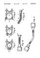
- FIG. 1is a perspective view of a fastener constructed in accordance with the present invention and shown releasably securing a lock to an upright post of a bicycle frame;
- FIG. 2is an enlarged perspective of the fastener shown in FIG. 1;
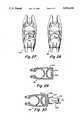
- FIG. 3is a view similar to FIG. 2 but showing a different embodiment thereof;
- FIG. 4is a plan view of the fastener shown in FIG. 2;
- FIG. 5is a plan view of the fastener shown in FIG. 3;
- FIG. 6is a perspective view of the fastener shown in FIG. 3, illustrating its geometry about a longitudinal axis and two transverse axes parallel to one another and normal to the longitudinal axis;
- FIG. 7is a fragmentary sectional view along the line 7--7 of FIG. 1;
- FIGS. 8 and 9are views similar to FIG. 7 but showing the same fastener mounted to larger diameter posts of a bicycle frame;
- FIGS. 10-18illustrate various embodiments of bolts designed to secure the fastener of the invention to bicycle posts of different sizes
- FIGS. 19-25 and 29-30in horizontal cross section, further of a fastener constructed in accordance present invention
- FIG. 20Ais a plan view of a bicycle lock provided with a member for use with the fastener illustrated in FIG. 20;
- FIG. 26is a fragmentary elevation along the line 26--26 of FIG. 25, but without also showing the post;
- FIGS. 27 and 28are perspective views of further embodiments of fasteners constructed in accordance with the present invention.
- FIGS. 31-31illustrate blister packages for displaying and selling the products of the invention.
- FIGS. 1, 2, 4, 7, 8 and 9one preferred embodiment of a fastener 10 for releasably securing a bicycle lock 12 to an upright post 14 of a bicycle frame is illustrated in FIGS. 1, 2, 4, 7, 8 and 9.
- the bicycle lock 12is comprised of a U-shaped shackle 16 and a cross bar 18 connected across the open end of the shackle 16.
- Fastener 10is an improvement over the bicycle clamp disclosed and claimed in our previous U.S. Pat. No. 4,736,921 granted Apr. 12, 1988 and assigned to KBL Corporation, which is a predecessor in name of the within assignee, the KRYPTONITE Corporation.
- the fastener 10is formed as an integral body 20 of a hard, resilient plastic material, such as a linear polyamide, including nylon, in a suitable mold and preferably by injection molding.
- the integral body 20includes a pair of opposed retainer portions 22 and 24 and a medial portion 26 therebetween.
- the retainer portions 22 and 24 and the medial portion 26extend along a longitudinal axis 28, observe FIG. 4.
- Retainer portion 22has an opening 30 defined by a pair of jaws 32, 34, with inner surfaces 36 developed by a paraxial locus of linear increments about a first transverse axis 38.
- Medial portion 26has an opening 40 with one inner surface 42 developed by a paraxial locus of linear increments about a second transverse axis 44. Another inner surface 46 is developed by a paraxial locus of linear increments about the first transverse axis 38.
- the first transverse axis 38 and the second transverse axis 44are parallel to each other and both are normal to the longitudinal axis 28.
- the paraxial locus of the retainer portion 22presents a curved seat for snugly receiving the post 14 of a bicycle frame, the curved seat having a curved cross section, note FIG. 7.
- the post 14is formed with a diameter of one inch.
- the pair of jaws 32, 34 of the retainer portion 22are flexible so as to make the opening 30 adaptable for snugly receiving a post 48, observe FIG. 8, of a bicycle frame, not shown, whose diameter is greater than that of post 14.
- the post 48is formed with a diameter of 11/8 inches.
- the pair of jaws 32, 34are in fact so flexible as to make the opening 30 defined thereby adaptable for singly receiving a post 49 whose diameter is 11/2 inches, observe FIG. 9.
- the paraxial loci of the surfaces 42 and 46 of the opening 40 in the medial portion 26provide a buffer for mechanically and flexibly isolating the configurations of the pair of opposed retainer portions 22 and 24 from each other.
- the cross sectional configurations of the opening 40 in the medial portion 26 and the opening 30 of the retainer portion 22 in a plane along the longitudinal axis 28 and normal to the transverse axes 38 and 44are such that the opening 40 is cusped and defined by a curve which is defined by the other inner surface 46, which curve is spaced from and lies along the curve of the curved seat defined by the inner surface 36.
- the opening 40is bounded by lines 41 and 43 which are paraxial to the longitudinal axis 28.
- the retainer portion 24is provided with a plurality of axial ridges 25 which are beveled at least at their upper ends.
- the pair of jaws 32 and 34are used to secure the fastener 10 to the post 14 of the bicycle by a bolt 50, which is a straight bolt or a sex bolt.
- Bolt 50preferably formed with a hexagonal head 52 to fit into a hexagonal opening 54, also can be formed as a break-away bolt illustrated in FIG. 12, with four segments separated by three break-away sections 51.
- the boltalso can be formed with a round head 53, in which case two screw drivers are needed to tighten the bolt, observe FIG. 10.
- a straight bolt or a sex boltcan still be used with the 11/8" post 48.
- an oversized bolt 56such as a bent bolt, is required.
- Bent bolt 56can be formed of two pieces, as illustrated on an enlarged scale in FIG. 14, or it can comprise three pieces, as illustrated in FIG. 11.
- the two-piece straight bolts illustrated in FIGS. 10 and 13differ one from the other in length and that the longer version's bolt is smooth for most of its axial length. This smoothness is desired lest the bolt scratches the post of the bicycle, adversely affecting its appearance.
- the same considerationsapply when the bolt is bent, see bolt 56, FIGS. 9 and 14. In all other respects, the bolts illustrated in FIGS.
- FIGS. 15 and 17are both formed with a chamfer 58.
- a bolt formed with a combination step and chamfer 59may be preferably, note FIGS. 16 and 18.
- FIGS. 3, 5 and 6A second preferred embodiment of a fastener 60 for releasably securing the bicycle lock 12 to the upright posts 14, 48 or 49 is illustrated in FIGS. 3, 5 and 6.
- Fastener 60essentially differs from the fastener 10 in being sturdier, hence heavier, in construction to accommodate heavier locks 12.
- Fastener 60also is formed as an integral body 62 of a hard, resilient plastic material, such as a linear polyamide, including nylon, in a suitable mold and preferably by injection molding. Integral body 62 also includes a pair of opposed retainer portions 64 and 66 and a medial portion 68 therebetween. The retainer portions 64 and 66 and the medial portion 68 extend along a longitudinal axis 70, note FIGS. 5 and 6. Retainer portion 64 has an opening 72 defined by a pair of jaws 74 and 76, with inner surfaces 78 developed by a paraxial locus of linear increments ⁇ C about a first transverse axis 80.
- a hard, resilient plastic materialsuch as a linear polyamide, including nylon
- Medial portion 68has an opening 82 with our inner surface 84 developed by a paraxial locus of linear increments ⁇ B about a second transverse axis 86. Another inner surface 88 is developed by a paraxial locus of linear increments ⁇ D about the first transverse axis 80.
- Retainer portion 66also has an opening 90 with inner surfaces 92 developed by a paraxial locus of linear increments ⁇ A about the second transverse axis 86. Opening 90 is larger than the opening 72.
- Transverse axes 80 and 86are parallel to each other and both are normal to the longitudinal axis 70.
- the paraxial locus ⁇ C of the retainer portion 64also presents a curved seat for snugly receiving any one of the posts 14, 48 and 49 of a bicycle frame, with the curved seat having a curved cross section.
- the pair of jaws 74 and 76also are flexible so as to make the opening 72 adaptable for snugly receiving one of the posts 14, 48 and 49, ranging in diameters from one inch to 11/2 inches.
- the paraxial loci of the surfaces 84 and 88, ⁇ B and ⁇ D respectively, of the opening 82 in the medial portion 68provide a buffer for mechanically and flexibly isolating the configurations of the pair of opposed retainer portions 64 and 66 from each other.
- the cross sectional configurations of the opening 82 in the medial portion 68 and of the opening 72 of the retainer portion 64 in a plane along the longitudinal axis 70 and normal to the transverse axes 80 and 86are such that the opening 82 is cusped and defined by a curve which is defined by the second inner surface 88, which curve is spaced from and lies along the curve of the curved seat defined by the inner surface 78.
- the opening 82is bounded by lines 83 and 85 which are not parallel but rather convergent to the longitudinal axis 70 in the direction of the jaws 74, 76.
- the retainer portion 66features a smooth inner surface 92. If desired, the inner surface 92 also can be provided with a plurality of ridges, just like the ridges 25 of the retainer portion 24. Still further, the fastener 60, unlike the fastener 10, is provided with a pair of stabilizing extensions 94 and 96.
- stabilizing extensions 94 and 96are intended firstly, to give added strength to the fastener 60 in the medial portion 68 thereof, and, secondly, to give added stability to the fastener 60, when mounted to the post 14, against vertical tilting when a heavy bicycle lock is inserted therein.
- FIGS. 19 and 21-24The embodiments of a fastener according to the invention and illustrated in FIGS. 19 and 21-24 have been developed to secure bicycle locks that have configurations other than circular. In all other respects, the fasteners illustrated therein are just the like the fasteners 10 or 60 shown and described above.
- FIG. 19a fastener 100 formed with an integral body of hard, resilient plastic material that includes a pair of opposed retainer portions 102 and 104 and a medial portion 106 therebetween.
- Retainer portion 102has an opening 108 defined by a pair of jaws 110 and 112 with inner surfaces 114 developed by a paraxial locus of linear increments about a first transverse axis, just like retainer portions 22 or 64 above.
- this first retainer portionwith its opening defined by the pair of jaws, has been omitted for sake of brevity, it being understood that they also are flexible so as to accommodate bicycle posts of sizes ranging form one inch to 11/2 inches.
- the fastener 100differs from the fasteners 10 and 60 in that the retainer portion 104 has an opening 116 with a cross sectional configuration which is octogonal to accommodate octogonal shaped locks or accessories.
- the medial portion 106features an opening 118 that is cusped, with one inner surface 113 being circular about the axis of opening 108, but a second inner surface 115 which is not circular about the axis of the opening 116. This second surface 115 preferably follows the shape of the opening 116. If desired, the second surface 115 also can be formed circular about the axis of the opening 116.
- the fasteners illustrated in fragmentary section in FIGS. 21-24respectively illustrate second retainer portions 120, 122, 124 and 126 whose internal cross sectional configuration is square, oval, pentagonal and hexagonal, respectively.
- the respective medial portions of these fastenersare cusped, with a first circular surface about the first transverse axis of the corresponding first retainer portion.
- the second surface of the cusped interior of the medial portionpreferably and for the most part follows the configuration of the second retainer portion. This second surface of the cusped interior however, also can be circular if desired, observe FIG. 22.
- FIG. 20there is illustrated another embodiment of a fastener 130 according to the invention and formed with an integral body of hard, resilient plastic material that includes a pair of opposed retainer portions 132 and 134 and a medial portion 136 therebetween.
- Retainer portion 132also has an opening 138 defined by a pair of jaws 140, 142, with inner surfaces 144 developed by a paraxial locus of linear increments about a first transverse axis, just like in the fastener 10 and 60.
- the medial portion 136also has an opening 146 which is cusped and formed just as opening 40 of the fastener 10, note FIG. 4.
- the second retainer portion 134is, however, unlike those above described and instead is formed with an opening 148 defined by a semicircle 150 and a diameter 152.
- a plurality of ridges 154can be provided about these surfaces bounding the opening 148, as shown, or the ridges 154 may be omitted, if desired.
- the opening 148 of the fastener 130is designed to receive an appropriately shaped mounting member 156, observe FIG. 20A, of a bicycle accessory, herein illustrated as another lock 158.
- the mounting member 156preferably is formed as an integral part of the bicycle accessory, which may include a water bottle, a first aid kit, or the like.
- FIGS. 25-26there is illustrated in horizontal cross section and in vertical elevation respectively, a fastener 160 according to the invention and formed with an integral body of hard, resilient plastic material that includes a pair of opposed retainer portions 162 and 164 and a medial portion 166 therebetween.
- Retainer portion 162has an opening 168 defined by a pair of jaws 170, 172 and with inner surfaces also developed by a paraxial locus of linear increments about a first transverse axis 174. It will be noted that, unlike the opening 30 of the fastener 10, the opening 168 is bounded by a semi-circle, and the jaws 170, 172, do not feature any holes to accommodate a bolt.
- a hole 176is provided centrally through both walls 173 and 175 defining the retainer portions 162 and 164 centrally in the medial portion 166, with the hole 176 being horizontally aligned to admit therethrough a mounting screw 178.
- the screw 178is used to mount the fastener 160 to a post 180 of a bicycle frame.
- the opening of the second retainer portion 164is circular about a second transverse axis 182 and the opening formed within the medial portion 166 is cusped, just like in the fastener 10, observe FIG. 4.
- fasteners 186 and 188 illustrated in FIGS. 27 and 28are designed to be mounted over protruding water bottle mounts, not shown, that are provided on upright posts of certain bicycles. Such protruding water bottle mounts are designed to be accommodated either within a hole 190 or a hole 192 formed within a depression 194. In all other respects, both fasteners 186 and 188 are identical with the fastener 10 described above.
- fasteners 196 and 198 illustrated respectively in FIGS. 29 and 30are designed to secure to a post of a bicycle frame another accessory, namely a derailleur 202.
- Fastener 196is similar to the fastener 130 illustrated in FIG. 20. It differs therefrom only with respect to a second retainer portion 200 which is smaller than the retainer portion 134 of the fastener 130, and that it is provided with a pair of mounting holes 204 and 206.
- Fastener 198differs from the fastener 196 only with respect to the specifics of mounting the derailleur 202 thereto.
- the rear mounting wall 208 of the second retainer portion 210is thicker and, in lieu of the mounting holes 204, 206, is formed with a mounting bracket 212. Bracket 212 is designed to secure thereto, via a pin 214, a clamp 216.
- a second pin 218in turn is designed flexibly to secure thereto the derailleur 202.
- FIGS. 31-33are illustrated three types of blister packages 220, 222 and 224, indicating one type of display of the products of the invention.
- blister package 220displays a bicycle lock 226, the fastener 10, and a number of bolts 228.
- Blister package 222displays the fastener 10 and the bolts 228, and blister package 224 displays only the bolts 228.
Landscapes
- Engineering & Computer Science (AREA)
- Mechanical Engineering (AREA)
- Connection Of Plates (AREA)
Abstract
Description
Claims (30)
Priority Applications (1)
| Application Number | Priority Date | Filing Date | Title |
|---|---|---|---|
| US07/490,731US5076526A (en) | 1990-03-07 | 1990-03-07 | Fastener for bicycle accessories |
Applications Claiming Priority (1)
| Application Number | Priority Date | Filing Date | Title |
|---|---|---|---|
| US07/490,731US5076526A (en) | 1990-03-07 | 1990-03-07 | Fastener for bicycle accessories |
Publications (1)
| Publication Number | Publication Date |
|---|---|
| US5076526Atrue US5076526A (en) | 1991-12-31 |
Family
ID=23949233
Family Applications (1)
| Application Number | Title | Priority Date | Filing Date |
|---|---|---|---|
| US07/490,731Expired - Fee RelatedUS5076526A (en) | 1990-03-07 | 1990-03-07 | Fastener for bicycle accessories |
Country Status (1)
| Country | Link |
|---|---|
| US (1) | US5076526A (en) |
Cited By (30)
| Publication number | Priority date | Publication date | Assignee | Title |
|---|---|---|---|---|
| USD335814S (en) | 1991-09-09 | 1993-05-25 | Ara Dabandjian | Bicycle lock mounting bracket |
| USD343349S (en) | 1991-08-12 | 1994-01-18 | Byrd Jr Richard H | U-lock spacer barrier |
| US5386961A (en)* | 1993-04-26 | 1995-02-07 | Interseng Hardware Company L.T.D. | Multi-directional mounting unit for mounting a bicycle lock on a tubular frame |
| US5405113A (en)* | 1994-01-24 | 1995-04-11 | Jaw; Chin-Woei | Bicycle padlock holder |
| USD358542S (en) | 1993-12-06 | 1995-05-23 | Byrd Jr Richard H | U-lock spacer barrier |
| US5458308A (en)* | 1993-12-27 | 1995-10-17 | Lin; Wen-Yii | U-type lock supporter |
| US5538167A (en)* | 1995-03-03 | 1996-07-23 | Winner International Royalty Corporation | Holder for securing a bicycle accessory to a bicycle frame |
| US5546776A (en)* | 1994-11-21 | 1996-08-20 | Sun; Min-Hsiung | Padlock and lock holder unit |
| US5551609A (en)* | 1994-05-09 | 1996-09-03 | Best; Paul S. | Bicycle rack with integral lock holder |
| EP0776817A2 (en) | 1995-12-01 | 1997-06-04 | Kryptonite Corporation | Bicycle lock bracket |
| US5653365A (en)* | 1996-06-12 | 1997-08-05 | Simple Locksmith Co., Ltd. | Supporting bracket of lock for bicycle |
| US5662255A (en)* | 1995-11-30 | 1997-09-02 | Lu; Chien-Chzh | Lock holder for fastening to a motorcycle for carrying a motorcycle lock |
| US5709113A (en)* | 1996-03-20 | 1998-01-20 | Winner International Royalty Corporation | Self-storing security device |
| US5833188A (en)* | 1994-12-20 | 1998-11-10 | Twofish Unlimited | Accessory mounting apparatus |
| US6195846B1 (en) | 1999-08-04 | 2001-03-06 | Robert Douglas Studdiford | Fastener having a block with cradle and method |
| US6321961B1 (en) | 1999-09-03 | 2001-11-27 | Kryptonite Corporation | Bicycle retention bracket |
| WO2002024516A1 (en) | 2000-09-22 | 2002-03-28 | Kryptonite Corporation | Bicycle lock holder |
| US6557808B1 (en)* | 2002-02-13 | 2003-05-06 | Renny Tse-Haw Ling | Two-piece detachable holder |
| EP1352820A1 (en)* | 2002-04-08 | 2003-10-15 | ABUS August Bremicker Söhne KG | Article attachment device for cycles |
| US20080230102A1 (en)* | 2007-03-20 | 2008-09-25 | Emily Blumenthal | Umbrella Attachment Device |
| US20090050681A1 (en)* | 2006-05-04 | 2009-02-26 | Mattel, Inc. | Octagonal containers |
| EP1854711A3 (en)* | 2006-05-12 | 2010-11-17 | ABUS August Bremicker Söhne KG | Mounting for a bicycle lock |
| US9079626B2 (en) | 2011-05-25 | 2015-07-14 | Robert David Zuraski | Portable lock mounting assemblies |
| US9340997B2 (en) | 2011-05-25 | 2016-05-17 | Ingersoll-Rand Company | Lock mounting assemblies for transportation devices |
| US20160368552A1 (en)* | 2015-06-22 | 2016-12-22 | ABUS August Bremicker Söhne KG | Holder |
| US20170135502A1 (en)* | 2015-11-18 | 2017-05-18 | Nam Thanh Nguyen | Display and storage bottle clip for fingernail lacquer bottles |
| USD798689S1 (en)* | 2015-09-17 | 2017-10-03 | Bell Sports, Inc. | Bicycle lock |
| US10961778B2 (en)* | 2016-08-11 | 2021-03-30 | Bobo Ladders Llc | Boat or recreational vehicle ladder apparatus |
| US12169036B2 (en) | 2020-07-29 | 2024-12-17 | Ctking, Llc | Flexible U-bolt assembly |
| US20250034911A1 (en)* | 2023-07-24 | 2025-01-30 | John Gillespie | Device and method for storing a lock |
Citations (22)
| Publication number | Priority date | Publication date | Assignee | Title |
|---|---|---|---|---|
| GB189711325A (en)* | 1897-05-06 | 1898-04-23 | John Frederick Sargeant | Improvements in Supports for Umbrellas, Guards, Sails, and the like, attachable to Velocipedes, Motor Cars, and like Vehicles. |
| US765213A (en)* | 1904-02-01 | 1904-07-19 | Robert W Thompson | Memorandum attachment for telephones. |
| US795782A (en)* | 1905-07-25 | Arthur H Porter | Lantern-holder. | |
| US1402725A (en)* | 1919-12-11 | 1922-01-03 | Howard L Pippen | Cycle lock |
| US1629859A (en)* | 1926-03-02 | 1927-05-24 | Lot F Burke | Lock holder |
| GB555662A (en)* | 1942-05-19 | 1943-09-01 | Douglas Nield | Improvements connected with clips for cycle pumps or the like |
| US2686029A (en)* | 1952-08-25 | 1954-08-10 | Charles F Raymond | Bracket for attaching flagpoles to parking meters |
| US2916237A (en)* | 1956-07-05 | 1959-12-08 | Mc Graw Edison Co | Electric service bracket for pipe mounting |
| US3581354A (en)* | 1969-09-16 | 1971-06-01 | Enco Mfg Co | Instrument clamp |
| US3591211A (en)* | 1969-08-28 | 1971-07-06 | Massey Ferguson Inc | Support bar clamp |
| US3747166A (en)* | 1971-05-21 | 1973-07-24 | Instrumentation Industries | Hose holder |
| US3848783A (en)* | 1973-04-12 | 1974-11-19 | Fort Lock Corp | Bicycle lock carrying bracket |
| US3924426A (en)* | 1973-11-23 | 1975-12-09 | Ernest Zane | Lock for bicycles and the like |
| US3967475A (en)* | 1975-04-04 | 1976-07-06 | Zane Michael S | Combination bicycle lock and mounting bracket |
| DE2818943A1 (en)* | 1977-04-29 | 1978-11-02 | Kbl Corp | LOCK FOR A BICYCLE OR DGL. WITH FASTENING PART |
| US4176770A (en)* | 1978-08-28 | 1979-12-04 | Tumbleweed Enterprises | Motorcycle canteen |
| FR2441079A1 (en)* | 1978-11-10 | 1980-06-06 | Obertino & Fils Jean | Two=way clip securing ticket on round bar - uses twin preformed metal strips riveted together back to back to obtain elastic pincers at each end |
| DE3008984A1 (en)* | 1980-03-08 | 1981-09-17 | Carl Hepting & Co, Lederwaren- und Gürtelfabrik, GmbH, 7000 Stuttgart | Securing clamp for motorcycle pannier - has two sliding clamp halves to grip frame with adjustable fitting |
| US4436232A (en)* | 1981-11-16 | 1984-03-13 | Kbl Corporation | Bracket for motorcycle lock |
| US4545224A (en)* | 1983-10-27 | 1985-10-08 | Kbl Corporation | Bicycle lock |
| US4730470A (en)* | 1986-09-05 | 1988-03-15 | Kbl Corp. | Security lock |
| US4736921A (en)* | 1985-05-24 | 1988-04-12 | Kbl Corporation | Clamp for holding bicycle lock |
- 1990
- 1990-03-07USUS07/490,731patent/US5076526A/ennot_activeExpired - Fee Related
Patent Citations (23)
| Publication number | Priority date | Publication date | Assignee | Title |
|---|---|---|---|---|
| US795782A (en)* | 1905-07-25 | Arthur H Porter | Lantern-holder. | |
| GB189711325A (en)* | 1897-05-06 | 1898-04-23 | John Frederick Sargeant | Improvements in Supports for Umbrellas, Guards, Sails, and the like, attachable to Velocipedes, Motor Cars, and like Vehicles. |
| US765213A (en)* | 1904-02-01 | 1904-07-19 | Robert W Thompson | Memorandum attachment for telephones. |
| US1402725A (en)* | 1919-12-11 | 1922-01-03 | Howard L Pippen | Cycle lock |
| US1629859A (en)* | 1926-03-02 | 1927-05-24 | Lot F Burke | Lock holder |
| GB555662A (en)* | 1942-05-19 | 1943-09-01 | Douglas Nield | Improvements connected with clips for cycle pumps or the like |
| US2686029A (en)* | 1952-08-25 | 1954-08-10 | Charles F Raymond | Bracket for attaching flagpoles to parking meters |
| US2916237A (en)* | 1956-07-05 | 1959-12-08 | Mc Graw Edison Co | Electric service bracket for pipe mounting |
| US3591211A (en)* | 1969-08-28 | 1971-07-06 | Massey Ferguson Inc | Support bar clamp |
| US3581354A (en)* | 1969-09-16 | 1971-06-01 | Enco Mfg Co | Instrument clamp |
| US3747166A (en)* | 1971-05-21 | 1973-07-24 | Instrumentation Industries | Hose holder |
| US3848783A (en)* | 1973-04-12 | 1974-11-19 | Fort Lock Corp | Bicycle lock carrying bracket |
| US3924426A (en)* | 1973-11-23 | 1975-12-09 | Ernest Zane | Lock for bicycles and the like |
| US3967475A (en)* | 1975-04-04 | 1976-07-06 | Zane Michael S | Combination bicycle lock and mounting bracket |
| DE2818943A1 (en)* | 1977-04-29 | 1978-11-02 | Kbl Corp | LOCK FOR A BICYCLE OR DGL. WITH FASTENING PART |
| US4155231A (en)* | 1977-04-29 | 1979-05-22 | Kbl Corporation | Bicycle lock and bracket |
| US4176770A (en)* | 1978-08-28 | 1979-12-04 | Tumbleweed Enterprises | Motorcycle canteen |
| FR2441079A1 (en)* | 1978-11-10 | 1980-06-06 | Obertino & Fils Jean | Two=way clip securing ticket on round bar - uses twin preformed metal strips riveted together back to back to obtain elastic pincers at each end |
| DE3008984A1 (en)* | 1980-03-08 | 1981-09-17 | Carl Hepting & Co, Lederwaren- und Gürtelfabrik, GmbH, 7000 Stuttgart | Securing clamp for motorcycle pannier - has two sliding clamp halves to grip frame with adjustable fitting |
| US4436232A (en)* | 1981-11-16 | 1984-03-13 | Kbl Corporation | Bracket for motorcycle lock |
| US4545224A (en)* | 1983-10-27 | 1985-10-08 | Kbl Corporation | Bicycle lock |
| US4736921A (en)* | 1985-05-24 | 1988-04-12 | Kbl Corporation | Clamp for holding bicycle lock |
| US4730470A (en)* | 1986-09-05 | 1988-03-15 | Kbl Corp. | Security lock |
Cited By (42)
| Publication number | Priority date | Publication date | Assignee | Title |
|---|---|---|---|---|
| USD343349S (en) | 1991-08-12 | 1994-01-18 | Byrd Jr Richard H | U-lock spacer barrier |
| USD335814S (en) | 1991-09-09 | 1993-05-25 | Ara Dabandjian | Bicycle lock mounting bracket |
| US5386961A (en)* | 1993-04-26 | 1995-02-07 | Interseng Hardware Company L.T.D. | Multi-directional mounting unit for mounting a bicycle lock on a tubular frame |
| USD358542S (en) | 1993-12-06 | 1995-05-23 | Byrd Jr Richard H | U-lock spacer barrier |
| US5458308A (en)* | 1993-12-27 | 1995-10-17 | Lin; Wen-Yii | U-type lock supporter |
| US5405113A (en)* | 1994-01-24 | 1995-04-11 | Jaw; Chin-Woei | Bicycle padlock holder |
| US5551609A (en)* | 1994-05-09 | 1996-09-03 | Best; Paul S. | Bicycle rack with integral lock holder |
| US5546776A (en)* | 1994-11-21 | 1996-08-20 | Sun; Min-Hsiung | Padlock and lock holder unit |
| US5833188A (en)* | 1994-12-20 | 1998-11-10 | Twofish Unlimited | Accessory mounting apparatus |
| US5538167A (en)* | 1995-03-03 | 1996-07-23 | Winner International Royalty Corporation | Holder for securing a bicycle accessory to a bicycle frame |
| US5662255A (en)* | 1995-11-30 | 1997-09-02 | Lu; Chien-Chzh | Lock holder for fastening to a motorcycle for carrying a motorcycle lock |
| EP0776817A2 (en) | 1995-12-01 | 1997-06-04 | Kryptonite Corporation | Bicycle lock bracket |
| US5647520A (en)* | 1995-12-01 | 1997-07-15 | Kryptonite Corporation | Bicycle lock bracket with splines |
| EP0776817A3 (en)* | 1995-12-01 | 1998-02-04 | Kryptonite Corporation | Bicycle lock bracket |
| US5709113A (en)* | 1996-03-20 | 1998-01-20 | Winner International Royalty Corporation | Self-storing security device |
| US5653365A (en)* | 1996-06-12 | 1997-08-05 | Simple Locksmith Co., Ltd. | Supporting bracket of lock for bicycle |
| US6195846B1 (en) | 1999-08-04 | 2001-03-06 | Robert Douglas Studdiford | Fastener having a block with cradle and method |
| US6321961B1 (en) | 1999-09-03 | 2001-11-27 | Kryptonite Corporation | Bicycle retention bracket |
| WO2002024516A1 (en) | 2000-09-22 | 2002-03-28 | Kryptonite Corporation | Bicycle lock holder |
| US6557808B1 (en)* | 2002-02-13 | 2003-05-06 | Renny Tse-Haw Ling | Two-piece detachable holder |
| EP1352820A1 (en)* | 2002-04-08 | 2003-10-15 | ABUS August Bremicker Söhne KG | Article attachment device for cycles |
| US20090050681A1 (en)* | 2006-05-04 | 2009-02-26 | Mattel, Inc. | Octagonal containers |
| US8240547B2 (en) | 2006-05-04 | 2012-08-14 | Mattel, Inc. | Octagonal containers |
| EP1854711A3 (en)* | 2006-05-12 | 2010-11-17 | ABUS August Bremicker Söhne KG | Mounting for a bicycle lock |
| US20080230102A1 (en)* | 2007-03-20 | 2008-09-25 | Emily Blumenthal | Umbrella Attachment Device |
| US7631654B2 (en)* | 2007-03-20 | 2009-12-15 | Emily Blumenthal | Umbrella attachment device |
| US9822557B2 (en) | 2011-05-25 | 2017-11-21 | Schlage Lock Company Llc | Portable lock mounting assemblies |
| US10501135B2 (en)* | 2011-05-25 | 2019-12-10 | Schlage Lock Company Llc | Lock mounting assemblies for transportation devices |
| US11745815B2 (en) | 2011-05-25 | 2023-09-05 | Schlage Lock Company Llc | Lock mounting assemblies for transportation devices |
| US11110980B2 (en) | 2011-05-25 | 2021-09-07 | Schlage Lock Company Llc | Lock mounting assemblies for transportation devices |
| US10711491B2 (en) | 2011-05-25 | 2020-07-14 | Schlage Lock Company Llc | Portable lock mounting assemblies |
| US9079626B2 (en) | 2011-05-25 | 2015-07-14 | Robert David Zuraski | Portable lock mounting assemblies |
| US10035552B2 (en) | 2011-05-25 | 2018-07-31 | Schlage Lock Company Llc | Lock mounting assemblies for transportation devices |
| US9340997B2 (en) | 2011-05-25 | 2016-05-17 | Ingersoll-Rand Company | Lock mounting assemblies for transportation devices |
| US20190061849A1 (en)* | 2011-05-25 | 2019-02-28 | Schlage Lock Company Llc | Lock mounting assemblies for transportation devices |
| US10081404B2 (en)* | 2015-06-22 | 2018-09-25 | ABUS August Bremicker Söhne KG | Holder |
| US20160368552A1 (en)* | 2015-06-22 | 2016-12-22 | ABUS August Bremicker Söhne KG | Holder |
| USD798689S1 (en)* | 2015-09-17 | 2017-10-03 | Bell Sports, Inc. | Bicycle lock |
| US20170135502A1 (en)* | 2015-11-18 | 2017-05-18 | Nam Thanh Nguyen | Display and storage bottle clip for fingernail lacquer bottles |
| US10961778B2 (en)* | 2016-08-11 | 2021-03-30 | Bobo Ladders Llc | Boat or recreational vehicle ladder apparatus |
| US12169036B2 (en) | 2020-07-29 | 2024-12-17 | Ctking, Llc | Flexible U-bolt assembly |
| US20250034911A1 (en)* | 2023-07-24 | 2025-01-30 | John Gillespie | Device and method for storing a lock |
Similar Documents
| Publication | Publication Date | Title |
|---|---|---|
| US5076526A (en) | Fastener for bicycle accessories | |
| US4736921A (en) | Clamp for holding bicycle lock | |
| US5649632A (en) | Fixture assembly for pipe materials | |
| US5957352A (en) | Tool holding device designed to be attached to a wheelbarrow | |
| US7334499B2 (en) | Grip for handlebar of bicycle | |
| US5435473A (en) | Lockable fishing rod holder | |
| US5743411A (en) | Open frame, self standing bicycle parking module | |
| US5476202A (en) | Automobile mounted multiple bike and ski racks | |
| US5372287A (en) | Article carrier | |
| US20170037884A1 (en) | Adaptable fastening mechanisms for various sized tubing | |
| US20080001046A1 (en) | Portable sign and barricade assemblies and plastic molded uprights and light and flag mounts therefor | |
| US3380697A (en) | Portable steps for climbing trees or poles | |
| WO1996019132A1 (en) | Bicycle accessory mounting apparatus | |
| EP0613112B1 (en) | Display holder | |
| US20040021042A1 (en) | Ring-post fastener | |
| US20100263583A1 (en) | Flag-Mounting Device for Vehicles | |
| US20040020954A1 (en) | Offset holding device | |
| US20040037667A1 (en) | Ring-post fastener | |
| WO1998041439A1 (en) | Side loading water bottle holder | |
| US5167353A (en) | "U" post bracket for bicycles | |
| US20240032689A1 (en) | Bottle storage device | |
| US5119690A (en) | Handlebar assembly for cycles | |
| US20030222184A1 (en) | Axial oval mount for elongate article having a flexible tie | |
| US20120037677A1 (en) | Container holder for a bicycle | |
| US5538167A (en) | Holder for securing a bicycle accessory to a bicycle frame |
Legal Events
| Date | Code | Title | Description |
|---|---|---|---|
| AS | Assignment | Owner name:KRYPTONITE CORPORATION, 95 FREEPORT STREET, BOSTON Free format text:ASSIGNMENT OF ASSIGNORS INTEREST.;ASSIGNOR:ZANE, PETER L.;REEL/FRAME:005641/0083 Effective date:19900307 | |
| FEPP | Fee payment procedure | Free format text:PAYOR NUMBER ASSIGNED (ORIGINAL EVENT CODE: ASPN); ENTITY STATUS OF PATENT OWNER: SMALL ENTITY | |
| AS | Assignment | Owner name:BAYBANK, MASSACHUSETTS Free format text:SECURITY INTEREST;ASSIGNOR:KRYPTONITE CORPORATION;REEL/FRAME:006554/0456 Effective date:19921125 | |
| REMI | Maintenance fee reminder mailed | ||
| FEPP | Fee payment procedure | Free format text:PAYER NUMBER DE-ASSIGNED (ORIGINAL EVENT CODE: RMPN); ENTITY STATUS OF PATENT OWNER: SMALL ENTITY | |
| LAPS | Lapse for failure to pay maintenance fees | ||
| FP | Lapsed due to failure to pay maintenance fee | Effective date:19960103 | |
| AS | Assignment | Owner name:SCHLAGE LOCK COMPANY, INDIANA Free format text:MERGER;ASSIGNOR:KRYPTONITE CORPORATION;REEL/FRAME:030999/0944 Effective date:20020501 | |
| AS | Assignment | Owner name:JPMORGAN CHASE BANK, N.A., AS ADMINISTRATIVE AGENT Free format text:SECURITY AGREEMENT;ASSIGNOR:SCHLAGE LOCK COMPANY LLC;REEL/FRAME:031831/0091 Effective date:20131126 | |
| AS | Assignment | Owner name:JPMORGAN CHASE BANK, N.A., AS ADMINISTRATIVE AGENT Free format text:SECURITY AGREEMENT;ASSIGNOR:SCHLAGE LOCK COMPANY LLC;REEL/FRAME:034173/0001 Effective date:20141015 | |
| STCH | Information on status: patent discontinuation | Free format text:PATENT EXPIRED DUE TO NONPAYMENT OF MAINTENANCE FEES UNDER 37 CFR 1.362 |