US5073982A - Apparatus for connecting multiple passive stars in a fiber optic network - Google Patents
Apparatus for connecting multiple passive stars in a fiber optic networkDownload PDFInfo
- Publication number
- US5073982A US5073982AUS07/402,195US40219589AUS5073982AUS 5073982 AUS5073982 AUS 5073982AUS 40219589 AUS40219589 AUS 40219589AUS 5073982 AUS5073982 AUS 5073982A
- Authority
- US
- United States
- Prior art keywords
- signal
- passive
- stars
- combination
- set forth
- Prior art date
- Legal status (The legal status is an assumption and is not a legal conclusion. Google has not performed a legal analysis and makes no representation as to the accuracy of the status listed.)
- Expired - Fee Related
Links
- 239000000835fiberSubstances0.000titleclaimsabstractdescription20
- 230000005540biological transmissionEffects0.000claimsabstractdescription20
- 238000012360testing methodMethods0.000claimsdescription15
- 230000000903blocking effectEffects0.000claimsdescription7
- 230000008054signal transmissionEffects0.000claimsdescription4
- 230000002457bidirectional effectEffects0.000claimsdescription2
- 230000003287optical effectEffects0.000description15
- 230000000694effectsEffects0.000description10
- 238000010586diagramMethods0.000description3
- 238000002592echocardiographyMethods0.000description2
- 238000003780insertionMethods0.000description2
- 230000037431insertionEffects0.000description2
- 230000007704transitionEffects0.000description2
- WWSJZGAPAVMETJ-UHFFFAOYSA-N2-[4-[2-(2,3-dihydro-1H-inden-2-ylamino)pyrimidin-5-yl]-3-ethoxypyrazol-1-yl]-1-(2,4,6,7-tetrahydrotriazolo[4,5-c]pyridin-5-yl)ethanoneChemical compoundC1C(CC2=CC=CC=C12)NC1=NC=C(C=N1)C=1C(=NN(C=1)CC(=O)N1CC2=C(CC1)NN=N2)OCCWWSJZGAPAVMETJ-UHFFFAOYSA-N0.000description1
- 238000004891communicationMethods0.000description1
- 239000002131composite materialSubstances0.000description1
- 238000010276constructionMethods0.000description1
- 238000013461designMethods0.000description1
- 230000004927fusionEffects0.000description1
- 230000002401inhibitory effectEffects0.000description1
- 238000000034methodMethods0.000description1
- 230000005693optoelectronicsEffects0.000description1
- 230000000737periodic effectEffects0.000description1
- 238000011084recoveryMethods0.000description1
- 238000009877renderingMethods0.000description1
- 238000012552reviewMethods0.000description1
- 230000035945sensitivityEffects0.000description1
- 238000012546transferMethods0.000description1
Images


Classifications
- H—ELECTRICITY
- H04—ELECTRIC COMMUNICATION TECHNIQUE
- H04B—TRANSMISSION
- H04B10/00—Transmission systems employing electromagnetic waves other than radio-waves, e.g. infrared, visible or ultraviolet light, or employing corpuscular radiation, e.g. quantum communication
- H04B10/27—Arrangements for networking
- H04B10/271—Combination of different networks, e.g. star and ring configuration in the same network or two ring networks interconnected
- H—ELECTRICITY
- H04—ELECTRIC COMMUNICATION TECHNIQUE
- H04B—TRANSMISSION
- H04B10/00—Transmission systems employing electromagnetic waves other than radio-waves, e.g. infrared, visible or ultraviolet light, or employing corpuscular radiation, e.g. quantum communication
- H04B10/27—Arrangements for networking
- H04B10/272—Star-type networks or tree-type networks
- H04B10/2725—Star-type networks without a headend
Definitions
- the present inventionis concerned with local area networks, and more particularly, with fiber optic token bus networks utilizing active and passive star couplers.
- Fiber optic networksutilize various architectures or interconnect techniques for providing communication access between all nodes or users on the network. Configurations such as rings, tapped linear buses and star coupled buses are common examples of such architectures. Star coupled networks have several known advantages over other types of networks.
- An optical star coupleris a passive, optical mixing element of either a transmissive or reflective variety.
- the transmissive star coupler(which uses a fusion region for the signal mixing) is the more common of the two. Any signal entering an input port of a passive star is divided and sent to all output ports, creating an effective bus interconnection. There is, however, a practical limit to the size (i.e., number of ports) that can be constructed, an exemplary number being 64.
- apparatusfor use in a fiber optic network which includes first an second passive stars and means providing a bidirectional signal transmission path between each of the passive stars and the apparatus.
- the apparatuscomprises in combination first means adapted for storing a value representing the round trip signal delay time between the apparatus and each of the passive stars, second means adapted to receive a signal from each of the passive stars, third means adapted to transmit the signal to each of the passive stars, fourth means coupled to the second and third means and adapted to respond to a signal received from one of the passive stars for blocking transmission of a signal back to that passive star during the time duration that the signal is being received from the one passive star, and fifth means coupled to the first means and the second means and adapted to block receipt of a signal from the other of the passive stars for a time which is a function of the duration of the received signal plus the time of the round trip signal delay stored in the first means.
- FIG. 1is a typical passive star coupler connected to multiple users or more particularly the network interface portions thereof in accordance with the prior art and which is used in conjunction with the present invention
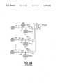
- FIG. 2is a local area network system including a plurality of the passive star couplers of FIG. 1 interconnected with an active component star;
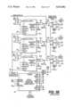
- FIGS. 3A and 3Bhereinafter collectively, FIG. 3, illustrate selected portions of an active star structure of the type utilized in FIG. 2;
- FIG. 4illustrates the structure of a portion of FIG. 3 concerned with determining and storing round-trip delay time between the active star and each passive star coupler to which it is connected;
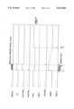
- FIGS. 5, 6 and 7are timing diagrams useful in understanding the operation of FIGS. 3 and 4.
- Passive star coupler 10 or passive star 10is available from a number of manufacturers, such as Model No. TCS64X64, manufactured by Canstar, 3900 Victoria Park Avenue, North York, Ontario, Canada.
- Passive star 10has N signal input terminals 12-1, 12-2 . . . 12-N and N signal output terminals 14-1, 14-2 . . . 14-N, each coupled to an associated network interface unit.
- Two exemplary network interface units 16-1 and 16-Nare illustrated. Connection between the passive star 10 and network interface unit 16 is by means of fiber optic transmission lines such as 18-1, 18-N, 20-1 and 20-N.
- the purpose of the network interface unitis to convert between electrical signals utilized by users such as user 1 connected to network interface unit 16-1, and corresponding optical signals utilized by optical transmission line 18 and passive star 10.
- the network's interface unitsare standard devices available from a number of manufacturers such as Model MFV-21, available from Computrol, 15 Ethan Allen Highway, Ridgefield, Conn.
- fiber optic transmission line 18-1connects between the transmitter (X) output of network interface unit 16-1 and input 12-1 of passive star 10 allowing electrical signals generated by user 1 to be transmitted as optical signals over transmission line 18-1.
- a typical output of passive star 10such as 14-1 is connected via optical transmission line 20-1 to the receiving (R) input of network interface 16-1 where the optical signal passing through transmission line 20-1 is connected to an electrical signal and passed to user 1.
- the network of FIG. 1commonly operates in what is known as a token bus configuration. That is, only one user, and therefore one network interface unit at a time, transmits a desired signal beginning with the address of the desired user. Assuming, for example, that user 1 wishes to transmit a signal via network interface 1 to a selected one of the plurality of network interface units 16 and users, the signal produced by user 1 is converted to an optical signal and passed via transmission line 18-1 to passive star coupler 10. A signal input at any of the input terminals 12-1 . . . 12-N of passive star coupler 10 are transmitted to all output terminals 14-1 . . . 14-N and to all of the respective network interface units including, in this instance, network interface 16-1.
- User 1has circuitry (not illustrated) which identifies the received signal over transmission line 20-1 as being not its destination and does not utilize the signal. However, the signal is transmitted, as indicated above, to all other network interface units and therefore to all other users to be used by the selected one of them.
- a limited number of userscan be connected to any one of passive star couplers 10, an exemplary number being 64. It is not possible to add more users by simply connecting one set of output and input terminals of one passive star respectively, to one set of input and output terminals of an additional passive star since the signal sent to this additional star from any originating passive star will be reflected back from all receiving stars causing multiple reflections on the overall star network. In addition, the insertion loss of the additional passive star may cause excessive signal attenuation, rendering the signal non-recoverable at the network interface unit receivers.
- an active star arrangementis illustrated in which a plurality of passive stars 10, for example 10-1, 10-2 . . . 10-N, are coupled to active star 30.
- the number of users N connected to a passive staris not necessarily the same as the number of passive stars N that can be connected to an active star.
- Each passive star 10is of the type illustrated in FIG. 1 and may be coupled to multiple users as illustrated in FIGS. 1 and 2.
- Each passive star and its usersis termed a sub-network.
- the problem in general with such an arrangement as illustrated in FIG. 2is that, when a signal is transmitted to active star 30, it behaves similarly to a typical passive star in that it transmits signals received at any input terminal back to all passive stars including the one that transmitted to it in the first place, causing undesired signal reflections.
- WDMWavelength Division Multiplexing
- Active star 30includes a plurality of input terminals 32-1 . . . 32-N and a like plurality of output terminals 34-1 . . . 34-N.
- Input terminal 32-1is connected via a fiber optic transmission line 36-1 to passive star 10-1 (FIG. 2) while output terminal 34-1 is connected via fiber optic cable 38-1 to an input of passive star 10-1 (FIG. 2).
- Other passive starsare connected in a similar manner to various ones of the input terminals 32 and output terminals 34 of active star 30.
- Each input terminal such as 32-1 within active star 30is connected to a fiber optic receiver (FOR) such as 40-1 which converts optical signals received thereat into electrical signals.
- FORfiber optic receiver
- each output terminal such as 34-1is coupled to receive an optical signal from a fiber optic transmitter (FOX) such as 42-1 which acts to convert electrical signals received at its input terminal 44 into optical signals for transmission over transmission line 38-1.
- FXfiber optic transmitter
- Transmitters 42-2, 42-N and other transmittersare of a similar type as transmitter 42-1 and perform in a similar manner.
- Fiber optic receivers 40-2, 40-N, and other fiber optic receiversare similar in construction and operation to fiber optic receiver 40-1.
- the output of fiber optic receiver 40-1is connected to an activity detector circuit 44-1 and as one input to an AND gate 46-1.
- Activity detector 44-1is responsive to the presence of an input signal at fiber optic receiver 40-1 to produce a pulse corresponding in time and time duration to that of the input signal at output AD 1 .
- the pulseitself will be appropriately referred to as AD 1 .
- Activity detectors 44-2, 44-N and other activity detectors 44-X(not shown) operate in a similar manner to that described for activity detector 44-1.
- the outputs of AND gates 46-1, 46-2, 46-N and of other AND gates 46-Xare coupled to respective inputs of an OR gate 48.
- the output of OR gate 48is optionally coupled to data recovery (restrobe) and reclocking circuitry (not shown and not relevant to the purposes of the present invention).
- the output of AND gate 50-1is coupled to one input (A) of a multiplexer 52-1.
- the output of multiplexer 50-1is coupled to the input of FOX 42-1.
- FOX 42converts electrical signals received thereat into optical signals for transmission to terminal 34-1 and thence to the input of the passive star 10-1 to which fiber optic transmitter 42-1 is coupled. Similar remarks apply to the interconnection of other AND gates 50-X, multiplexers 52-X and associated fiber optic transmitters 42-X where X is 2 through N.
- each circuit 60-Xprovides a means to determine and store the round trip signal delay to its respective star 10-X and to inhibit transmission and receipt of messages to and from the various passive stars.
- each activity detector 44-Xexcept for one, are coupled to respective inputs of OR gates 62-X, the outputs of which are coupled to the DELAY START x input of respective modules 60-X.
- the one exception in each caseis the particular AD x signal associated with that module.
- signal AD 2is not applied to OR gate 62-2.
- Sequencer 64is essentially a timing circuit responsive to the various AD x signals and other external signals applied thereto for providing various output timed pulses as indicated in FIGS. 5, 6 and 7. From a review of FIGS. 5, 6 and 7 a person of ordinary skill in the art could easily construct sequencer 64 so no further details thereof will be given.
- a set of three timing outputs, INIT x , START x and CALC x from sequencer 60is coupled to similarly legended inputs of a respective module 60-X.
- An ENABLE output from sequencer 64is coupled to and enables a signal generator 66 to produce a signal burst output of predetermined value at GEN OUT.
- GEN OUTis coupled as a second (B) input to each of multiplexers 52-X.
- the various CALC x outputs from sequencer 64are coupled to select (SEL) inputs of respective multiplexers 52-X to determine which signal input, that at A or B, is output to FOX 42-X.
- the output ENIN x of each module 60-Xis coupled to a second input of NAND gate 54-X and to a second input of AND gate 46-X.
- the output of NAND gate 54-Xis a signal ENOUT x (enable output X) and is coupled to an AND gate 50-X.
- a clock oscillator 68produces periodic pulses of frequency f which are coupled to the CK inputs of each of modules 60-X.
- An exemplary frequencyis 100 MHz.
- CALC xis coupled to the UP/DOWN input of a standard digital counter 70 to make the counter count up or down depending on the value, logic level 1 (hereinafter LL1) of the CALC x signal.
- LL1logic level 1
- CALC xis also coupled to the input of an inverter 72, the output of which is OPERATE x , and to one input of AND gate 74.
- the AD x inputis coupled to the second input of gate 74 while its output is coupled to one input of OR gate 76 and the clock input of a latch 78.
- the output of OR gate 76is coupled to the STOP COUNT input of counter 70.
- the DELAY START x input to module X and the output from an inverter 72are coupled to the two inputs of AND gate 80, the output of which is coupled to the input of + (positive) and - (negative) pulse generators 82 and 84, respectively.
- the output of generator 84 and the START x inputare coupled to respective inputs of OR gate 86, the output of which is coupled to the START COUNT input of counter 70.
- the output of generator 82is coupled to the LOAD input of counter 70 and the reset (R) input of flip-flop 88.
- the Q output of latch 78is coupled over multiconductor wires, indicated as such by cross-hatching 90, to the LOAD DATA input of counter 70, while the Q OUT output of counter 70 is coupled to the D input of latch 78.
- the CK input to module 60is coupled to the CLOCK input of counter 70.
- a module 60-Xwhere X may be any number from 1 to N, after a sub-network comprising a passive star coupler 10 (FIG. 1) and users, if any, connected thereto has been added to the overall network comprising other passive star couplers, other users, and active star 30.
- a passive starAfter a passive star has been added to the network, a first requirement is to determine the round trip signal delay time from the active star to the newly added passive star and back to the active star.
- the timing diagram of FIG. 5will be used as an aid to explain how the round trip delay is calculated.
- a typically longer ENABLE pulseis also produced by sequencer 64.
- the ENABLE pulseas illustrated in FIGS. 3 and 5, commencing at time T 1 (FIG. 5) triggers signal generator 66 to produce a predetermined test signal for a duration T 2 -T 1 .
- the outputmay be of any desired value which is understood to be a test signal and not a data signal.
- the signal GEN OUTis transmitted to all multiplexers 52-X. However, only one multiplexer, that which is selected by an appropriate CALC x signal will pass the GEN OUT signal to its associated FOX and to the newly added passive star.
- the transmitted test signalwill be received from the passive star at the appropriate terminal 32-X as an optical signal and converted by FOR 40-X into an equivalent electrical signal.
- activity detector 44-Xwith the CALC x signal at LL1 and AD x also LL1, AND gate 74 is enabled.
- the resulting LL1 output pulseenables OR gate 76 to issue a STOP COUNT pulse to counter 70.
- the LL1 signal from enabled AND gate 74also enables the clock input of latch 78 to receive the count to which counter 70 has been driven into latch 78 via the Q OUT terminal of counter 70 and the D input terminal of latch 78.
- the count value in latch 78represents the round trip time of a signal to go between a passive star associated with latch 78 and the active star in both directions.
- CALC xis driven to LL0 (FIG. 5), due to the AD x signal being applied to the DONE x input of sequencer 64 in FIG. 3 and the active star is ready to receive data from and transmit data to the new passive star X.
- the delay valuemay be calculated by external means, and then be loaded into the appropriate passive star sub-network's latch. This could simplify the complexity of the active star's circuitry.
- the LL1 signal AD 1is applied to the AD terminal of module 60-1 but no action occurs since the LL0 CALC signal inhibits AND gate 74. Further, since AD 1 is not applied to OR gate 62-1 no LL1 delay START 1 signal is generated. With ENIN 1 at LL1 and AD 1 at LL1, ENOUT 1 is at LL0, inhibiting AND gate 50-1 so the message from passive star 1 is not retransmitted to passive star 1.
- the LL1 AD 1 signal marking the presence of a message from passive, star 1causes DELAY START x (X ⁇ 1) to go to LL1 for the duration of the message.
- the LL1 leading edge of the delay start pulsecauses plus or "positive edge" pulse generator 82 to produce a momentary pulse at time T 0 (FIG. 7) causing the counter 70 to load with the value stored in its related latch 78. It will be understood that the value stored in each latch 78 is typically different from all others and therefore the counters 70 will each contain a different value from the others.
- the pulse from + pulse generator 82resets flip-flop 88 causing its output, ENIN x to be at a LL0.
- the LL0blocks input from all other passive stars at AND gates 46X (FIG. 3).
Landscapes
- Engineering & Computer Science (AREA)
- Computing Systems (AREA)
- Physics & Mathematics (AREA)
- Electromagnetism (AREA)
- Computer Networks & Wireless Communication (AREA)
- Signal Processing (AREA)
- Small-Scale Networks (AREA)
Abstract
Description
Claims (14)
Priority Applications (1)
| Application Number | Priority Date | Filing Date | Title |
|---|---|---|---|
| US07/402,195US5073982A (en) | 1989-09-01 | 1989-09-01 | Apparatus for connecting multiple passive stars in a fiber optic network |
Applications Claiming Priority (1)
| Application Number | Priority Date | Filing Date | Title |
|---|---|---|---|
| US07/402,195US5073982A (en) | 1989-09-01 | 1989-09-01 | Apparatus for connecting multiple passive stars in a fiber optic network |
Publications (1)
| Publication Number | Publication Date |
|---|---|
| US5073982Atrue US5073982A (en) | 1991-12-17 |
Family
ID=23590923
Family Applications (1)
| Application Number | Title | Priority Date | Filing Date |
|---|---|---|---|
| US07/402,195Expired - Fee RelatedUS5073982A (en) | 1989-09-01 | 1989-09-01 | Apparatus for connecting multiple passive stars in a fiber optic network |
Country Status (1)
| Country | Link |
|---|---|
| US (1) | US5073982A (en) |
Cited By (31)
| Publication number | Priority date | Publication date | Assignee | Title |
|---|---|---|---|---|
| US5301056A (en)* | 1991-12-16 | 1994-04-05 | Motorola, Inc. | Optical distribution system |
| US5327277A (en)* | 1991-06-04 | 1994-07-05 | Alcatel N.V. | Method and apparatus for determining equalization delays in a transmission system and related apparatus |
| US5341232A (en)* | 1989-02-20 | 1994-08-23 | Licentia Patent-Verwaltung-Gmbh | Star-shaped network for data communication between stations |
| US5351241A (en)* | 1992-12-24 | 1994-09-27 | Intel Corporation | Twisted pair ethernet hub for a star local area network |
| US5485458A (en)* | 1993-03-05 | 1996-01-16 | Apple Computer, Inc. | Bus interconnect circuit including port control logic for a multiple node communication network |
| EP0645653A3 (en)* | 1993-08-27 | 1996-02-07 | Siemens Ag | Combined transmission and reception electro-optical device for optical fibers, in particular for use in a fiber-optic bus. |
| US5493657A (en)* | 1993-06-21 | 1996-02-20 | Apple Computer, Inc. | High speed dominant mode bus for differential signals |
| US5510920A (en)* | 1991-01-07 | 1996-04-23 | Fuji Xerox Co., Ltd. | Local area network |
| US5513369A (en)* | 1991-08-05 | 1996-04-30 | Ncr Corporation | Star coupler device including means for connecting multiple star couplers together in a cascaded relationship |
| US5523879A (en)* | 1991-04-26 | 1996-06-04 | Fuji Xerox Co., Ltd. | Optical link amplifier and a wavelength multiplex laser oscillator |
| US5579486A (en)* | 1993-01-14 | 1996-11-26 | Apple Computer, Inc. | Communication node with a first bus configuration for arbitration and a second bus configuration for data transfer |
| US5847852A (en)* | 1994-12-15 | 1998-12-08 | Nec Corporation | Optical network |
| RU2128885C1 (en)* | 1997-02-24 | 1999-04-10 | Военная академия Ракетных войск стратегического назначения им.Петра Великого | Fiber-optic information and diagnostic signal transmission system |
| DE19810287A1 (en)* | 1998-03-10 | 1999-09-16 | Bayerische Motoren Werke Ag | Databus for communication between several subscribers e.g. in vehicle |
| DE19810294A1 (en)* | 1998-03-10 | 1999-09-16 | Bayerische Motoren Werke Ag | Data bus for several subscribers that exchange data messages via at least one electrical cable e.g. in vehicle |
| US6211985B1 (en)* | 1997-08-08 | 2001-04-03 | Tyco Submarine Systems Ltd. | Remote monitoring of an optical transmission system using line monitoring signals |
| US20020048274A1 (en)* | 2000-08-10 | 2002-04-25 | Peter Fuhrmann | Activity detection in a star node with a plurality of coupled network nodes |
| US6744985B1 (en)* | 1998-03-10 | 2004-06-01 | Bayerische Motoren Werke Aktiengesellschaft | Data bus for a plurality of nodes |
| US20060171714A1 (en)* | 2005-02-02 | 2006-08-03 | Calix Networks, Inc. | Electrically shared passive optical network |
| RU2325764C2 (en)* | 2006-07-07 | 2008-05-27 | Институт вычислительных технологий СО РАН | Method of optical data transmission in optical fibre communication lines and device for its implementation |
| US7440697B1 (en) | 1998-03-10 | 2008-10-21 | Bayerische Motoren Werke Aktiengesellschaft | Data bus for a plurality of nodes |
| RU2362271C1 (en)* | 2007-11-01 | 2009-07-20 | Открытое акционерное общество "Информационные телекоммуникационные технологии" (ОАО "Интелтех") | Fibre-optic transmission system for detecting attempts at unauthorised access |
| RU2362270C2 (en)* | 2007-09-17 | 2009-07-20 | Открытое акционерное общество "Информационные телекоммуникационные технологии" (ОАО "Интелтех") | Fibre-optic transmission system for emergency situations |
| RU2380834C1 (en)* | 2008-06-23 | 2010-01-27 | Юрий Федорович Кутаев | Method for laser space communications and facility for its implementation |
| US20100028004A1 (en)* | 2008-08-01 | 2010-02-04 | Masaru Nishino | Optical communication device, optical communication system, optical output control method and program |
| US20100034210A1 (en)* | 2006-09-06 | 2010-02-11 | Nxp, B.V. | Cluster coupler in a time triggered network |
| RU2400933C1 (en)* | 2009-02-24 | 2010-09-27 | Федеральное государственное учреждение "Государственный научно-исследовательский испытательный институт проблем технической защиты информации Федеральной службы по техническому и экспортному контролю" | Method of information transfer in fibre optic system of data transfer with spectral multiplex |
| WO2011031186A1 (en)* | 2009-09-14 | 2011-03-17 | Grishachev Vladimir Vasilievich | Fiber-optic detector for detecting threats of verbal information leaks |
| US20120106960A1 (en)* | 2010-10-29 | 2012-05-03 | Lockheed Martin Corporation | Reliable load-balanced multi-photonic star configuration |
| RU2715176C1 (en)* | 2019-04-09 | 2020-02-25 | Федеральное государственное бюджетное учреждение "16 Центральный научно-исследовательский испытательный ордена Красной Звезды институт имени маршала войск связи А.И. Белова" Министерства обороны Российской Федерации | Apparatus for assessing acoustic environment of inspected object |
| US11133957B2 (en) | 2019-05-29 | 2021-09-28 | Trane International Inc. | HVAC controller area network hybrid network topology |
Citations (19)
| Publication number | Priority date | Publication date | Assignee | Title |
|---|---|---|---|---|
| US4227260A (en)* | 1978-11-06 | 1980-10-07 | The Singer Company | Electronic active star element for an optical data transmission system |
| US4270029A (en)* | 1978-03-23 | 1981-05-26 | Kokusai Denshin Denwa Kabushiki Kaisha | Selection system for digital signal repeaters |
| US4494185A (en)* | 1981-04-16 | 1985-01-15 | Ncr Corporation | Data processing system employing broadcast packet switching |
| US4516272A (en)* | 1982-02-15 | 1985-05-07 | Ricoh Company, Ltd. | Communication network |
| US4543666A (en)* | 1982-09-23 | 1985-09-24 | Siemens Aktiengesellschaft | Optical coupler network for coupling a plurality of subscriber transmitters to a plurality of subscriber receivers by means of optical star couplers |
| US4630254A (en)* | 1984-10-26 | 1986-12-16 | Trw Inc. | Controlled star network |
| US4641371A (en)* | 1985-01-16 | 1987-02-03 | Westinghouse Electric Corp. | Multi-star fiber optic network |
| US4644587A (en)* | 1981-12-03 | 1987-02-17 | Ricoh Company, Ltd. | Optical data communication system |
| US4646361A (en)* | 1983-03-10 | 1987-02-24 | Nec Corporation | Optical star repeater |
| US4654889A (en)* | 1985-02-05 | 1987-03-31 | Westinghouse Electric Corp. | Multi-star fiber optic network with improved access time |
| US4688260A (en)* | 1985-10-09 | 1987-08-18 | Westinghouse Electric Corp. | High-reliability fiber optic repeater |
| US4701909A (en)* | 1986-07-24 | 1987-10-20 | American Telephone And Telegraph Company, At&T Bell Laboratories | Collision detection technique for an optical passive star local area network using CSMA/CD |
| US4701756A (en)* | 1985-09-10 | 1987-10-20 | Burr William E | Fault-tolerant hierarchical network |
| US4712859A (en)* | 1985-09-19 | 1987-12-15 | Bell Communications Research, Inc. | Distributed star network |
| US4747094A (en)* | 1984-09-11 | 1988-05-24 | Kokusai Denshin Denwa Co., Ltd. | Signal coupling system for optical repeater system |
| US4781427A (en)* | 1985-09-19 | 1988-11-01 | The Mitre Corporation | Active star centered fiber optic local area network |
| US4797951A (en)* | 1985-11-23 | 1989-01-10 | International Computers Limited | Parallel optical data transmission system |
| US4805196A (en)* | 1987-04-29 | 1989-02-14 | Gte Laboratories Incorporated | Line delay compensation for digital transmission systems utilizing low power line drivers |
| US4977593A (en)* | 1987-11-27 | 1990-12-11 | British Telecommunications Plc | Optical communications network |
- 1989
- 1989-09-01USUS07/402,195patent/US5073982A/ennot_activeExpired - Fee Related
Patent Citations (19)
| Publication number | Priority date | Publication date | Assignee | Title |
|---|---|---|---|---|
| US4270029A (en)* | 1978-03-23 | 1981-05-26 | Kokusai Denshin Denwa Kabushiki Kaisha | Selection system for digital signal repeaters |
| US4227260A (en)* | 1978-11-06 | 1980-10-07 | The Singer Company | Electronic active star element for an optical data transmission system |
| US4494185A (en)* | 1981-04-16 | 1985-01-15 | Ncr Corporation | Data processing system employing broadcast packet switching |
| US4644587A (en)* | 1981-12-03 | 1987-02-17 | Ricoh Company, Ltd. | Optical data communication system |
| US4516272A (en)* | 1982-02-15 | 1985-05-07 | Ricoh Company, Ltd. | Communication network |
| US4543666A (en)* | 1982-09-23 | 1985-09-24 | Siemens Aktiengesellschaft | Optical coupler network for coupling a plurality of subscriber transmitters to a plurality of subscriber receivers by means of optical star couplers |
| US4646361A (en)* | 1983-03-10 | 1987-02-24 | Nec Corporation | Optical star repeater |
| US4747094A (en)* | 1984-09-11 | 1988-05-24 | Kokusai Denshin Denwa Co., Ltd. | Signal coupling system for optical repeater system |
| US4630254A (en)* | 1984-10-26 | 1986-12-16 | Trw Inc. | Controlled star network |
| US4641371A (en)* | 1985-01-16 | 1987-02-03 | Westinghouse Electric Corp. | Multi-star fiber optic network |
| US4654889A (en)* | 1985-02-05 | 1987-03-31 | Westinghouse Electric Corp. | Multi-star fiber optic network with improved access time |
| US4701756A (en)* | 1985-09-10 | 1987-10-20 | Burr William E | Fault-tolerant hierarchical network |
| US4712859A (en)* | 1985-09-19 | 1987-12-15 | Bell Communications Research, Inc. | Distributed star network |
| US4781427A (en)* | 1985-09-19 | 1988-11-01 | The Mitre Corporation | Active star centered fiber optic local area network |
| US4688260A (en)* | 1985-10-09 | 1987-08-18 | Westinghouse Electric Corp. | High-reliability fiber optic repeater |
| US4797951A (en)* | 1985-11-23 | 1989-01-10 | International Computers Limited | Parallel optical data transmission system |
| US4701909A (en)* | 1986-07-24 | 1987-10-20 | American Telephone And Telegraph Company, At&T Bell Laboratories | Collision detection technique for an optical passive star local area network using CSMA/CD |
| US4805196A (en)* | 1987-04-29 | 1989-02-14 | Gte Laboratories Incorporated | Line delay compensation for digital transmission systems utilizing low power line drivers |
| US4977593A (en)* | 1987-11-27 | 1990-12-11 | British Telecommunications Plc | Optical communications network |
Cited By (41)
| Publication number | Priority date | Publication date | Assignee | Title |
|---|---|---|---|---|
| US5341232A (en)* | 1989-02-20 | 1994-08-23 | Licentia Patent-Verwaltung-Gmbh | Star-shaped network for data communication between stations |
| US5510920A (en)* | 1991-01-07 | 1996-04-23 | Fuji Xerox Co., Ltd. | Local area network |
| US5773345A (en)* | 1991-04-26 | 1998-06-30 | Fuji Xerox Co., Ltd. | Optical link amplifier and a wavelength multiplex laser oscillator |
| US5570226A (en)* | 1991-04-26 | 1996-10-29 | Fuji Xerox Co., Ltd. | Optical link amplifier and a wavelength multiplex laser oscillator |
| US5523879A (en)* | 1991-04-26 | 1996-06-04 | Fuji Xerox Co., Ltd. | Optical link amplifier and a wavelength multiplex laser oscillator |
| US5327277A (en)* | 1991-06-04 | 1994-07-05 | Alcatel N.V. | Method and apparatus for determining equalization delays in a transmission system and related apparatus |
| US5513369A (en)* | 1991-08-05 | 1996-04-30 | Ncr Corporation | Star coupler device including means for connecting multiple star couplers together in a cascaded relationship |
| US5301056A (en)* | 1991-12-16 | 1994-04-05 | Motorola, Inc. | Optical distribution system |
| US5351241A (en)* | 1992-12-24 | 1994-09-27 | Intel Corporation | Twisted pair ethernet hub for a star local area network |
| US5579486A (en)* | 1993-01-14 | 1996-11-26 | Apple Computer, Inc. | Communication node with a first bus configuration for arbitration and a second bus configuration for data transfer |
| US5485458A (en)* | 1993-03-05 | 1996-01-16 | Apple Computer, Inc. | Bus interconnect circuit including port control logic for a multiple node communication network |
| US5493657A (en)* | 1993-06-21 | 1996-02-20 | Apple Computer, Inc. | High speed dominant mode bus for differential signals |
| EP0645653A3 (en)* | 1993-08-27 | 1996-02-07 | Siemens Ag | Combined transmission and reception electro-optical device for optical fibers, in particular for use in a fiber-optic bus. |
| US5847852A (en)* | 1994-12-15 | 1998-12-08 | Nec Corporation | Optical network |
| RU2128885C1 (en)* | 1997-02-24 | 1999-04-10 | Военная академия Ракетных войск стратегического назначения им.Петра Великого | Fiber-optic information and diagnostic signal transmission system |
| US6211985B1 (en)* | 1997-08-08 | 2001-04-03 | Tyco Submarine Systems Ltd. | Remote monitoring of an optical transmission system using line monitoring signals |
| US6366381B1 (en) | 1997-08-08 | 2002-04-02 | Tycom (Us) Inc. | Remote monitoring of an optical transmission system using line monitoring signals |
| US6744985B1 (en)* | 1998-03-10 | 2004-06-01 | Bayerische Motoren Werke Aktiengesellschaft | Data bus for a plurality of nodes |
| DE19810287A1 (en)* | 1998-03-10 | 1999-09-16 | Bayerische Motoren Werke Ag | Databus for communication between several subscribers e.g. in vehicle |
| US7440697B1 (en) | 1998-03-10 | 2008-10-21 | Bayerische Motoren Werke Aktiengesellschaft | Data bus for a plurality of nodes |
| DE19810294A1 (en)* | 1998-03-10 | 1999-09-16 | Bayerische Motoren Werke Ag | Data bus for several subscribers that exchange data messages via at least one electrical cable e.g. in vehicle |
| US20020048274A1 (en)* | 2000-08-10 | 2002-04-25 | Peter Fuhrmann | Activity detection in a star node with a plurality of coupled network nodes |
| US7035224B2 (en)* | 2000-08-10 | 2006-04-25 | Koninklijke Philips Electronics N.V. | Activity detection in a star node with a plurality of coupled network nodes |
| US20060171714A1 (en)* | 2005-02-02 | 2006-08-03 | Calix Networks, Inc. | Electrically shared passive optical network |
| RU2325764C2 (en)* | 2006-07-07 | 2008-05-27 | Институт вычислительных технологий СО РАН | Method of optical data transmission in optical fibre communication lines and device for its implementation |
| US9137042B2 (en)* | 2006-09-06 | 2015-09-15 | Nxp, B.V. | Cluster coupler in a time triggered network |
| US20100034210A1 (en)* | 2006-09-06 | 2010-02-11 | Nxp, B.V. | Cluster coupler in a time triggered network |
| RU2362270C2 (en)* | 2007-09-17 | 2009-07-20 | Открытое акционерное общество "Информационные телекоммуникационные технологии" (ОАО "Интелтех") | Fibre-optic transmission system for emergency situations |
| RU2362271C1 (en)* | 2007-11-01 | 2009-07-20 | Открытое акционерное общество "Информационные телекоммуникационные технологии" (ОАО "Интелтех") | Fibre-optic transmission system for detecting attempts at unauthorised access |
| RU2380834C1 (en)* | 2008-06-23 | 2010-01-27 | Юрий Федорович Кутаев | Method for laser space communications and facility for its implementation |
| US20100028004A1 (en)* | 2008-08-01 | 2010-02-04 | Masaru Nishino | Optical communication device, optical communication system, optical output control method and program |
| RU2421912C2 (en)* | 2008-08-01 | 2011-06-20 | Нек Корпорейшн | Device of optical communication, system of optical communication, method and programme to control output of optical signals |
| US8190023B2 (en) | 2008-08-01 | 2012-05-29 | Nec Corporation | Optical communication device, optical communication system, optical output control method and program |
| RU2400933C1 (en)* | 2009-02-24 | 2010-09-27 | Федеральное государственное учреждение "Государственный научно-исследовательский испытательный институт проблем технической защиты информации Федеральной службы по техническому и экспортному контролю" | Method of information transfer in fibre optic system of data transfer with spectral multiplex |
| WO2011031186A1 (en)* | 2009-09-14 | 2011-03-17 | Grishachev Vladimir Vasilievich | Fiber-optic detector for detecting threats of verbal information leaks |
| RU2428798C2 (en)* | 2009-09-14 | 2011-09-10 | Владимир Васильевич Гришачев | Fibre optic detector of voice information leakage threats via fibre optic communications |
| US20120106960A1 (en)* | 2010-10-29 | 2012-05-03 | Lockheed Martin Corporation | Reliable load-balanced multi-photonic star configuration |
| US8467682B2 (en)* | 2010-10-29 | 2013-06-18 | Lockheed Martin Corporation | Reliable load-balanced multi-photonic star configuration |
| RU2715176C1 (en)* | 2019-04-09 | 2020-02-25 | Федеральное государственное бюджетное учреждение "16 Центральный научно-исследовательский испытательный ордена Красной Звезды институт имени маршала войск связи А.И. Белова" Министерства обороны Российской Федерации | Apparatus for assessing acoustic environment of inspected object |
| US11133957B2 (en) | 2019-05-29 | 2021-09-28 | Trane International Inc. | HVAC controller area network hybrid network topology |
| US11729018B2 (en) | 2019-05-29 | 2023-08-15 | Trane International Inc. | HVAC controller area network hybrid network topology |
Similar Documents
| Publication | Publication Date | Title |
|---|---|---|
| US5073982A (en) | Apparatus for connecting multiple passive stars in a fiber optic network | |
| US4850042A (en) | Dual media local area network interfacing | |
| US4797901A (en) | Circuit arrangement for testing a passive bus network with the carrier sense multiple access with collisions detection method | |
| US4700344A (en) | Processor overrun circuit | |
| CA1204847A (en) | Device for transmitting coded messages between stations | |
| FR2527030A1 (en) | MULTIPLEX TIME TRANSMISSION SYSTEM | |
| CA1209712A (en) | Method and installation for sending digital data | |
| US4288869A (en) | Half-duplex/simplex digital signal converter | |
| JP2002507086A (en) | Data bus for multiple nodes | |
| EP0166915B1 (en) | Communication system | |
| US4809363A (en) | Method for automatic level matching in a local network, in particular a multicomputer arrangement, comprising a bus system having light waveguides, for the purpose of collision recognition | |
| US4333176A (en) | Data extraction means for use in a data transmission system | |
| US4882580A (en) | Communication system | |
| FR2553245A1 (en) | DATA TRANSMISSION SYSTEM | |
| US5513369A (en) | Star coupler device including means for connecting multiple star couplers together in a cascaded relationship | |
| US4229623A (en) | Receiving means for use in a high speed, low noise digital data communication system | |
| FR2556913A1 (en) | DEVICE FOR SEMAPHORIC TERMINALS FOR SIGNALING SYSTEM NO. 7 | |
| SU1392573A1 (en) | Device for simulating data transmission and processing system | |
| US3727008A (en) | Dial pulse and multiple frequency signalling sender/multiple frequency signalling receiver apparatus | |
| RU2050018C1 (en) | Device for receiving and transmission of binary signals | |
| EP0515519A1 (en) | Network interconnection apparatus | |
| SU1352443A1 (en) | Information transmission device | |
| Farrington et al. | An optical-fiber multiterminal data system for aircraft | |
| JP3881088B2 (en) | Computer equipment | |
| SU1727213A1 (en) | Device for control over access to common communication channel |
Legal Events
| Date | Code | Title | Description |
|---|---|---|---|
| AS | Assignment | Owner name:GENERAL ELECTRIC COMPANY A CORP. OF NEW YORK Free format text:ASSIGNMENT OF ASSIGNORS INTEREST.;ASSIGNORS:VIOLA, JEFFREY P.;SERGI, JOSEPH B.;REEL/FRAME:005118/0980 Effective date:19890825 | |
| CC | Certificate of correction | ||
| AS | Assignment | Owner name:MARTIN MARIETTA CORPORATION, MARYLAND Free format text:ASSIGNMENT OF ASSIGNORS INTEREST;ASSIGNOR:GENERAL ELECTRIC COMPANY;REEL/FRAME:007046/0736 Effective date:19940322 | |
| FEPP | Fee payment procedure | Free format text:PAYOR NUMBER ASSIGNED (ORIGINAL EVENT CODE: ASPN); ENTITY STATUS OF PATENT OWNER: LARGE ENTITY | |
| FPAY | Fee payment | Year of fee payment:4 | |
| AS | Assignment | Owner name:LOCKHEED MARTIN CORPORATION, MARYLAND Free format text:ASSIGNMENT OF ASSIGNORS INTEREST;ASSIGNOR:MARTIN MARIETTA CORPORATION;REEL/FRAME:008628/0518 Effective date:19960128 | |
| FPAY | Fee payment | Year of fee payment:8 | |
| AS | Assignment | Owner name:L-3 COMMUNICATIONS CORPORATION, NEW YORK Free format text:ASSIGNMENT OF ASSIGNORS INTEREST;ASSIGNOR:LOCKHEED MARTIN CORPORATION, A CORP. OF MD;REEL/FRAME:010180/0073 Effective date:19970430 | |
| REMI | Maintenance fee reminder mailed | ||
| LAPS | Lapse for failure to pay maintenance fees | ||
| STCH | Information on status: patent discontinuation | Free format text:PATENT EXPIRED DUE TO NONPAYMENT OF MAINTENANCE FEES UNDER 37 CFR 1.362 | |
| FP | Lapsed due to failure to pay maintenance fee | Effective date:20031217 |