US5073166A - Method and apparatus for emplacement of a gastrostomy catheter - Google Patents
Method and apparatus for emplacement of a gastrostomy catheterDownload PDFInfo
- Publication number
- US5073166A US5073166AUS07/311,685US31168589AUS5073166AUS 5073166 AUS5073166 AUS 5073166AUS 31168589 AUS31168589 AUS 31168589AUS 5073166 AUS5073166 AUS 5073166A
- Authority
- US
- United States
- Prior art keywords
- section
- configuration
- anchor
- tube
- anchoring means
- Prior art date
- Legal status (The legal status is an assumption and is not a legal conclusion. Google has not performed a legal analysis and makes no representation as to the accuracy of the status listed.)
- Expired - Lifetime
Links
- 238000000034methodMethods0.000titleclaimsdescription45
- 238000003780insertionMethods0.000claimsabstractdescription93
- 230000037431insertionEffects0.000claimsabstractdescription93
- 239000012528membraneSubstances0.000claimsabstractdescription31
- 230000002829reductive effectEffects0.000claimsdescription7
- 238000004891communicationMethods0.000claimsdescription6
- 230000000284resting effectEffects0.000claimsdescription5
- 238000004873anchoringMethods0.000claims64
- 239000011248coating agentSubstances0.000claims1
- 238000000576coating methodMethods0.000claims1
- 230000000295complement effectEffects0.000claims1
- 230000007246mechanismEffects0.000abstractdescription146
- 210000002784stomachAnatomy0.000abstractdescription61
- 238000007789sealingMethods0.000abstractdescription3
- 210000004051gastric juiceAnatomy0.000abstractdescription2
- 210000004379membraneAnatomy0.000description24
- 239000012530fluidSubstances0.000description17
- 210000003815abdominal wallAnatomy0.000description10
- 238000013461designMethods0.000description10
- 230000035611feedingEffects0.000description9
- 239000000463materialSubstances0.000description7
- 229940079593drugDrugs0.000description6
- 239000003814drugSubstances0.000description6
- 210000003238esophagusAnatomy0.000description6
- 208000015181infectious diseaseDiseases0.000description5
- 230000014759maintenance of locationEffects0.000description5
- 235000015097nutrientsNutrition0.000description5
- 238000001839endoscopyMethods0.000description4
- 238000002483medicationMethods0.000description4
- 230000002496gastric effectEffects0.000description3
- 210000002445nippleAnatomy0.000description3
- 239000004033plasticSubstances0.000description3
- 238000011282treatmentMethods0.000description3
- 210000001835visceraAnatomy0.000description3
- 235000001674Agaricus brunnescensNutrition0.000description2
- 230000008901benefitEffects0.000description2
- 230000008878couplingEffects0.000description2
- 238000010168coupling processMethods0.000description2
- 238000005859coupling reactionMethods0.000description2
- 238000002695general anesthesiaMethods0.000description2
- 230000002458infectious effectEffects0.000description2
- 208000014674injuryDiseases0.000description2
- 239000002184metalSubstances0.000description2
- 210000004303peritoneumAnatomy0.000description2
- 230000008733traumaEffects0.000description2
- 206010002091AnaesthesiaDiseases0.000description1
- 229920001875EbonitePolymers0.000description1
- 239000004743PolypropyleneSubstances0.000description1
- 230000001154acute effectEffects0.000description1
- 239000000853adhesiveSubstances0.000description1
- 230000001070adhesive effectEffects0.000description1
- 230000037005anaesthesiaEffects0.000description1
- 239000000560biocompatible materialSubstances0.000description1
- 230000000740bleeding effectEffects0.000description1
- 238000005219brazingMethods0.000description1
- 230000006835compressionEffects0.000description1
- 238000007906compressionMethods0.000description1
- 230000001010compromised effectEffects0.000description1
- 230000006837decompressionEffects0.000description1
- 230000003247decreasing effectEffects0.000description1
- 238000011161developmentMethods0.000description1
- 238000000502dialysisMethods0.000description1
- 201000010099diseaseDiseases0.000description1
- 208000037265diseases, disorders, signs and symptomsDiseases0.000description1
- 238000009826distributionMethods0.000description1
- 239000013013elastic materialSubstances0.000description1
- 210000003195fasciaAnatomy0.000description1
- 239000000835fiberSubstances0.000description1
- 210000005095gastrointestinal systemAnatomy0.000description1
- 230000035876healingEffects0.000description1
- 230000036541healthEffects0.000description1
- 230000000774hypoallergenic effectEffects0.000description1
- 238000007689inspectionMethods0.000description1
- 238000005304joiningMethods0.000description1
- 230000000670limiting effectEffects0.000description1
- 239000003589local anesthetic agentSubstances0.000description1
- 230000007774longtermEffects0.000description1
- 230000000474nursing effectEffects0.000description1
- 230000035764nutritionEffects0.000description1
- 235000016709nutritionNutrition0.000description1
- 210000000056organAnatomy0.000description1
- 210000003200peritoneal cavityAnatomy0.000description1
- 206010034674peritonitisDiseases0.000description1
- -1polypropylenePolymers0.000description1
- 229920001155polypropylenePolymers0.000description1
- 229910052710siliconInorganic materials0.000description1
- 239000010703siliconSubstances0.000description1
- 230000007480spreadingEffects0.000description1
- 238000003892spreadingMethods0.000description1
- 239000000126substanceSubstances0.000description1
- 239000013589supplementSubstances0.000description1
- 238000001356surgical procedureMethods0.000description1
- 230000007704transitionEffects0.000description1
Images


Classifications
- A—HUMAN NECESSITIES
- A61—MEDICAL OR VETERINARY SCIENCE; HYGIENE
- A61M—DEVICES FOR INTRODUCING MEDIA INTO, OR ONTO, THE BODY; DEVICES FOR TRANSDUCING BODY MEDIA OR FOR TAKING MEDIA FROM THE BODY; DEVICES FOR PRODUCING OR ENDING SLEEP OR STUPOR
- A61M39/00—Tubes, tube connectors, tube couplings, valves, access sites or the like, specially adapted for medical use
- A61M39/02—Access sites
- A61M39/0247—Semi-permanent or permanent transcutaneous or percutaneous access sites to the inside of the body
- A—HUMAN NECESSITIES
- A61—MEDICAL OR VETERINARY SCIENCE; HYGIENE
- A61J—CONTAINERS SPECIALLY ADAPTED FOR MEDICAL OR PHARMACEUTICAL PURPOSES; DEVICES OR METHODS SPECIALLY ADAPTED FOR BRINGING PHARMACEUTICAL PRODUCTS INTO PARTICULAR PHYSICAL OR ADMINISTERING FORMS; DEVICES FOR ADMINISTERING FOOD OR MEDICINES ORALLY; BABY COMFORTERS; DEVICES FOR RECEIVING SPITTLE
- A61J15/00—Feeding-tubes for therapeutic purposes
- A61J15/0015—Gastrostomy feeding-tubes
- A—HUMAN NECESSITIES
- A61—MEDICAL OR VETERINARY SCIENCE; HYGIENE
- A61J—CONTAINERS SPECIALLY ADAPTED FOR MEDICAL OR PHARMACEUTICAL PURPOSES; DEVICES OR METHODS SPECIALLY ADAPTED FOR BRINGING PHARMACEUTICAL PRODUCTS INTO PARTICULAR PHYSICAL OR ADMINISTERING FORMS; DEVICES FOR ADMINISTERING FOOD OR MEDICINES ORALLY; BABY COMFORTERS; DEVICES FOR RECEIVING SPITTLE
- A61J15/00—Feeding-tubes for therapeutic purposes
- A61J15/0026—Parts, details or accessories for feeding-tubes
- A61J15/003—Means for fixing the tube inside the body, e.g. balloons, retaining means
- A61J15/0034—Retainers adjacent to a body opening to prevent that the tube slips through, e.g. bolsters
- A61J15/0038—Retainers adjacent to a body opening to prevent that the tube slips through, e.g. bolsters expandable, e.g. umbrella type
- A—HUMAN NECESSITIES
- A61—MEDICAL OR VETERINARY SCIENCE; HYGIENE
- A61M—DEVICES FOR INTRODUCING MEDIA INTO, OR ONTO, THE BODY; DEVICES FOR TRANSDUCING BODY MEDIA OR FOR TAKING MEDIA FROM THE BODY; DEVICES FOR PRODUCING OR ENDING SLEEP OR STUPOR
- A61M25/00—Catheters; Hollow probes
- A61M25/01—Introducing, guiding, advancing, emplacing or holding catheters
- A61M25/02—Holding devices, e.g. on the body
- A61M25/04—Holding devices, e.g. on the body in the body, e.g. expansible
- A—HUMAN NECESSITIES
- A61—MEDICAL OR VETERINARY SCIENCE; HYGIENE
- A61J—CONTAINERS SPECIALLY ADAPTED FOR MEDICAL OR PHARMACEUTICAL PURPOSES; DEVICES OR METHODS SPECIALLY ADAPTED FOR BRINGING PHARMACEUTICAL PRODUCTS INTO PARTICULAR PHYSICAL OR ADMINISTERING FORMS; DEVICES FOR ADMINISTERING FOOD OR MEDICINES ORALLY; BABY COMFORTERS; DEVICES FOR RECEIVING SPITTLE
- A61J15/00—Feeding-tubes for therapeutic purposes
- A61J15/0003—Nasal or oral feeding-tubes, e.g. tube entering body through nose or mouth
- A61J15/0007—Nasal or oral feeding-tubes, e.g. tube entering body through nose or mouth inserted by using a guide-wire
- A—HUMAN NECESSITIES
- A61—MEDICAL OR VETERINARY SCIENCE; HYGIENE
- A61J—CONTAINERS SPECIALLY ADAPTED FOR MEDICAL OR PHARMACEUTICAL PURPOSES; DEVICES OR METHODS SPECIALLY ADAPTED FOR BRINGING PHARMACEUTICAL PRODUCTS INTO PARTICULAR PHYSICAL OR ADMINISTERING FORMS; DEVICES FOR ADMINISTERING FOOD OR MEDICINES ORALLY; BABY COMFORTERS; DEVICES FOR RECEIVING SPITTLE
- A61J15/00—Feeding-tubes for therapeutic purposes
- A61J15/0026—Parts, details or accessories for feeding-tubes
- A61J15/0053—Means for fixing the tube outside of the body, e.g. by a special shape, by fixing it to the skin
- A61J15/0061—Means for fixing the tube outside of the body, e.g. by a special shape, by fixing it to the skin fixing at an intermediate position on the tube, i.e. tube protruding the fixing means
- A—HUMAN NECESSITIES
- A61—MEDICAL OR VETERINARY SCIENCE; HYGIENE
- A61M—DEVICES FOR INTRODUCING MEDIA INTO, OR ONTO, THE BODY; DEVICES FOR TRANSDUCING BODY MEDIA OR FOR TAKING MEDIA FROM THE BODY; DEVICES FOR PRODUCING OR ENDING SLEEP OR STUPOR
- A61M25/00—Catheters; Hollow probes
- A61M25/01—Introducing, guiding, advancing, emplacing or holding catheters
- A61M25/02—Holding devices, e.g. on the body
- A61M2025/0213—Holding devices, e.g. on the body where the catheter is attached by means specifically adapted to a part of the human body
- A61M2025/0233—Holding devices, e.g. on the body where the catheter is attached by means specifically adapted to a part of the human body specifically adapted for attaching to a body wall by means which are on both sides of the wall, e.g. for attaching to an abdominal wall
- A—HUMAN NECESSITIES
- A61—MEDICAL OR VETERINARY SCIENCE; HYGIENE
- A61M—DEVICES FOR INTRODUCING MEDIA INTO, OR ONTO, THE BODY; DEVICES FOR TRANSDUCING BODY MEDIA OR FOR TAKING MEDIA FROM THE BODY; DEVICES FOR PRODUCING OR ENDING SLEEP OR STUPOR
- A61M39/00—Tubes, tube connectors, tube couplings, valves, access sites or the like, specially adapted for medical use
- A61M39/02—Access sites
- A61M39/0247—Semi-permanent or permanent transcutaneous or percutaneous access sites to the inside of the body
- A61M2039/0255—Semi-permanent or permanent transcutaneous or percutaneous access sites to the inside of the body for access to the gastric or digestive system
- A—HUMAN NECESSITIES
- A61—MEDICAL OR VETERINARY SCIENCE; HYGIENE
- A61M—DEVICES FOR INTRODUCING MEDIA INTO, OR ONTO, THE BODY; DEVICES FOR TRANSDUCING BODY MEDIA OR FOR TAKING MEDIA FROM THE BODY; DEVICES FOR PRODUCING OR ENDING SLEEP OR STUPOR
- A61M39/00—Tubes, tube connectors, tube couplings, valves, access sites or the like, specially adapted for medical use
- A61M39/02—Access sites
- A61M39/0247—Semi-permanent or permanent transcutaneous or percutaneous access sites to the inside of the body
- A61M2039/0273—Semi-permanent or permanent transcutaneous or percutaneous access sites to the inside of the body for introducing catheters into the body
- A—HUMAN NECESSITIES
- A61—MEDICAL OR VETERINARY SCIENCE; HYGIENE
- A61M—DEVICES FOR INTRODUCING MEDIA INTO, OR ONTO, THE BODY; DEVICES FOR TRANSDUCING BODY MEDIA OR FOR TAKING MEDIA FROM THE BODY; DEVICES FOR PRODUCING OR ENDING SLEEP OR STUPOR
- A61M39/00—Tubes, tube connectors, tube couplings, valves, access sites or the like, specially adapted for medical use
- A61M39/02—Access sites
- A61M39/0247—Semi-permanent or permanent transcutaneous or percutaneous access sites to the inside of the body
- A61M2039/0297—Semi-permanent or permanent transcutaneous or percutaneous access sites to the inside of the body at least part of it being inflatable, e.g. for anchoring, sealing or removing
- A—HUMAN NECESSITIES
- A61—MEDICAL OR VETERINARY SCIENCE; HYGIENE
- A61M—DEVICES FOR INTRODUCING MEDIA INTO, OR ONTO, THE BODY; DEVICES FOR TRANSDUCING BODY MEDIA OR FOR TAKING MEDIA FROM THE BODY; DEVICES FOR PRODUCING OR ENDING SLEEP OR STUPOR
- A61M2210/00—Anatomical parts of the body
- A61M2210/10—Trunk
- A61M2210/1042—Alimentary tract
- A61M2210/1053—Stomach
Definitions
- This inventionrelates to a new gastrostomy feeding tube or catheter and method of insertion.
- Gastrostomy feedingshave been utilized since the late 1800s as a means of providing enteral nutrition to a patient who could not chew or swallow but otherwise had a functional gastro-intestinal system.
- the gastrostomy catheterallows the delivery of nutrients directly into the stomach of the patient.
- the PEG procedurecan be divided into two types of procedures, the "push” (or “stick) procedure and the "pull” procedure.
- This inventionrelates to the development of a new gastrostomy catheter designed as a new type of "push” procedure.
- an endoscopeis inserted through the esophagus of the patient, and the stomach is then inflated.
- a cannula or needleis then inserted through the stomach wall, and a string is inserted through the needle.
- the needlemay then be removed.
- the stringis grasped by means of a snare passing through the endoscope, and the endoscope and snare are pulled up through the esophagus, such that one end of the string comes out through the mouth, leaving the other end protruding through the opening made by the needle.
- a gastrostomy catheteris then tied to the end of the string which protrudes from the mouth, conventionally by means of another string attached at one end of the gastrostomy catheter.
- the catheteris then pulled down into the stomach, by pulling on the end of the string which protrudes through the opening in the stomach, and is pulled through the opening as well, usually being provided with a tapered dilator at the leading end to assist in passing through the stomach wall.
- the catheteris held in place by a retention means against the interior of the abdominal wall. Another retention means is placed on the exterior, so as to hold the catheter in place against the stomach.
- the endoscopeis reinserted to ensure proper placement of the catheter.
- the pull procedurehas several disadvantages, one of which is the fact that, for both emplacement and removal, an endoscope must be inserted into the patient's esophagus, requiring anesthesia and causing discomfort to the patient. Also, the catheter itself must pass through the patient's esophagus, once for emplacement and once for removal. This becomes even more problematic when secondary or replacement catheters are put in place, since each time the catheter is changed, the "pull" procedure must again be followed, with increased likelihood of trauma, infections, and other complications.
- the pull procedureis particularly difficult to carry out when a patient has an obstruction in the esophagus, which is a problem compounded by the fact that it is just such people who are likely to need the procedure.
- Another disadvantagearises from the fact that infectious or cancerous matter may be drawn from a diseased area in, for example, the throat, down into the stomach, with the possibility of spreading the disease further, especially to the area around the freshly formed opening in the stomach.
- Percutaneous gastrostomy techniquesare described in detail in articles by R. Miller, et al., "The Russell percutaneous endoscopic gastrostomy: key technical steps,” Gastrointestinal Endoscopy 1988: 34; 339-342, and T. Russell, et al., "Percutaneous Gastrostomy--A New Simplified and Cost-Effective Technique," American Journal of Surgery 1984:148; 132-137, which are incorporated herein by reference.
- a needleis first inserted into the stomach (at a site located by endoscopy, as with the pull procedure), and then a guide wire is inserted through a lumen in the needle.
- a small incisionis then made in the fascia next to the guide wire, after which an interiorly lubricated sheath having a splittable seam is guided, along with a tapered dilator, over the guide wire and into the stomach.
- the dilator and guide wireare removed, and a balloon catheter is inserted through the lubricated central lumen of the sheath.
- a distal balloon of the catheteris then inflated, and the sheath is peeled or split away along its seam or seams, thus leaving the catheter emplaced in the stomach. Sutures are provided to maintain tension of the balloon against the peritoneum.
- a disadvantage of the Russell procedureis that the splittable sheath is necessarily larger in diameter than the catheter which is inserted through it for emplacement within the stomach. Therefore, the opening into the stomach is made overly large, making sealing difficult and increasing the likelihood of infection.
- the sheathmay not be made too narrow, or the physician will not be able to insert the catheter through it, and thus there is a trade-off between insertability of the catheter and the quality of the seal once the catheter is in place.
- a gastrostomy catheterAfter a gastrostomy catheter is in place, it is desirable to replace it after a time with a secondary, or replacement catheter.
- a typical replacement catheteruses a flexible, enlarged tip attached at the distal end of the catheter.
- a rigid rodis inserted through a lumen of the catheter into the enlarged tip, and is pressed against the inside of the tip, thus stretching it out and decreasing its diameter.
- the tipis then inserted through the opening into the stomach, and the rod is removed, allowing the tip once again to enlarge, thus providing an anchor against removal of the catheter.
- This type of catheterdoes not provide a very reliable anchor, however, because the flexible tip may be stretched into a reduced-diameter configuration simply by a pull on the portion of the catheter which is exterior to the opening. Thus, there is always the concern that an accidental force on the catheter will result in its removal, perhaps with consequent damage to the area surrounding the opening and bleeding of the patient.
- a larger expanded diameterleads to a more reliable anchor, and is especially necessary in a flexible-tip design.
- a larger expanded diameterrequires a greater amount of material in the tip, and thus when the rod is used to stretch the tip out longitudinally, in order to reduce its diameter for insertion, this greater amount of material limits the minimum diameter, such that the tip, even when in its reduced state, may have a diameter appreciably larger than the diameter of the catheter. This leads to undesirable enlargement of the opening into the patient, resulting in less reliable sealing around the catheter once it is in place, and in greater likelihood of infection at the insertion site.
- Replacement cathetersoften have a shorter length than primary catheters, and thus there is the problem of possible fluid leakage from the stomach through the catheter. This is not so much a problem with a longer catheter, because back-pressure is developed by the fluid. Thus, with a shorter catheter, it is helpful to provide a valve somewhere along the catheter.
- valve used with replacement cathetersis screwed to the proximal end of the catheter. This has the disadvantage of being bulky and relatively expensive, and of requiring at least a two-part system.
- the internal retention mechanisma mechanically operated “mushroom” locking mechanism, is activated. Tension is placed on the catheter to position the stomach against the abdominal wall.
- This inventionprovides a simplified method of inserting all types of hollow and flexible catheters without the need for a dilator or an introducer sleeve.
- Another object of this inventionis to provide a permanent and secure method of fixing the catheter to the internal organ of the patient without the use of a balloon, a fixed ring, large plugs, or the like.
- the inventioncomprises a method and apparatus for emplacement of a gastrostomy catheter within a stomach.
- a gastrostomy catheter of the invention for primary emplacementincludes a proximal end, a main body, and a distal end, with a locking mechanism attached at the distal end.
- the locking mechanismincludes a first end, a second end, and a plurality of hinged legs carried therebetween.
- the locking mechanismhas a fully extended configuration and a retracted configuration. In the fully extended configuration, the outer diameter of the locking mechanism closely matches the outer diameter of the gastrostomy catheter. In the retracted configuration, branches of each of the hinged legs are pulled back until they meet one another, until a T-shaped cross section is achieved, and the outer diameter of the T-shape is much greater than the outer diameter of the gastrostomy catheter.
- the distal end of the locking mechanismincludes an inner bore and two locking knobs, and in addition includes both lateral and terminal ports.
- the proximal end of the gastrostomy catheteris configured for receiving conventional medical apparatus for providing nutrients, medications, or the like into the stomach of the patient.
- a plugis provided for closing off the lumen of the gastrostomy catheter.
- a flexible, elastic membraneis provided over the locking mechanism, and seals with the gastrostomy catheter and distal end of the locking mechanism.
- a continuous fluid passageis thus formed by the lumen of the gastrostomy catheter, the interior of the membrane, and the interior bore of the distal end of the locking mechanism.
- An insertion toolis used, which is preferably a long rigid rod with a handle and a plurality of longitudinal grooves at its distal end, each groove having a right-angled portion set back from the distal end.
- the insertion toolis inserted through the bore of the gastrostomy catheter until the longitudinal grooves receive the locking knobs of the distal end of the locking mechanism, and the insertion tool is then rotated such that the locking knobs enter the right-angled portions, thus locking the distal end of the insertion tool and the gastrostomy catheter with respect to longitudinal motion.
- a conventional needleis first inserted into the stomach of a patient, at a site located by endoscopy, and a flexible guide wire is inserted through a lumen in the needle.
- the needleis then removed, and the insertion tool and gastrostomy catheter (locked together as described above) are inserted over the guide wire, slightly enlarging the opening originally made by the needle.
- the gastrostomy catheteris somewhat flexible, such that it will fit tightly into this opening, and the insertion tool provides rigidity so that the catheter may be inserted through the opening.
- the locking mechanism of the primary insertion catheteris gradually tapered at its distal end, and the distal end of the locking mechanism is also gradually tapered and closely matches the diameter of the distal end of the locking mechanism, so as to minimize the enlargement of the opening into the stomach. This minimizes trauma to the patient, and provides a good seal against the passage of fluids or infectious material.
- a retaining ring or buttonis slidably attached to the exterior of the gastrostomy catheter, and is slid against the skin of the stomach of the patient.
- the operator of the devicepulls back on the insertion tool, until the locking mechanism is in its expanded configuration.
- the insertion toolis then removed, by first rotating it so as to disengage it from the locking mechanism, and then pulling it axially outwards.
- the expanded configuration of the locking mechanismis maintained by the tension of the membrane, which is elastic and contracts against the locking mechanism.
- the locking mechanismis biased slightly from the orthogonal when in the expanded configuration, such that the membrane, exerting an axially inward force on the mechanism, maintains it tightly in its expanded configuration.
- the gastrostomy catheteris maintained tightly in place by the retaining ring on the exterior of the patient's stomach and the locking mechanism on the interior thereof.
- the catheter tip of the inventioncan be introduced into the internal organs of the body, such as the gastric cavity, and then locked into place with the insertion tool. This provides permanent placement, secure against being accidentally dislodged by an unintentional pull, but permits easy removal with the appropriate tool.
- the retaining ringmay be unitary with or firmly attached to the gastrostomy catheter.
- the distal end of the locking mechanismmay be rounded, and the proximal end of the catheter is shorter, and includes an adaptor for accommodating conventional apparatus for supplying medicines, nutrients, or the like.
- a one-way flexible valveis preferably provided within the bore of the gastrostomy catheter to prevent backflow of gastric juices, medications, or the like.
- An alternative embodiment to the locking mechanismincludes detents on the branches of the mechanism, which interlock when the mechanism is expanded, thus maintaining the mechanism in the expanded configuration. In this embodiment, there is no need for the membrane described above relative to the earlier embodiments.
- the legs of the locking mechanismare biased forward by means of angles recesses situated in the body of the catheter, which are configured to closely match surfaces of the branches, such that, upon expansion of the mechanism, a predetermined angle is achieved by the mechanism.
- the locking mechanism and a main shaft of the catheterare held together by the engagement of teeth or threads attached to each, such that the effective length of the catheter may be altered. This allows for versatility in accommodating different widths of abdominal walls, such that one design of catheter may be used for many different patients.
- Another embodiment of the inventionincludes a locking mechanism with interior, axially disposed teeth carried on the distal end of the mechanism, which interlock with teeth carried on a collar attached to the branches of the mechanism.
- the teethinterlock with one another when the physician pulls back on the insertion tool, thus expanding the mechanism.
- the teethare allowed to disengage when the insertion tool is pulled yet further back, and the mechanism then collapses into a nonexpanded configuration, for removal of the catheter from the patient.
- a removal toolis provided for disengaging certain of the foregoing embodiments of the catheter of the invention, the tool having a shaft which is rectangular in cross section, such that when it is inserted into a central bore of the catheter, it engages the locking knobs carried in the distal end of the locking mechanism. The tool is then pushed forward, thereby disengaging the locking mechanism, which collapses into its nonexpanded configuration for removal from the patient.
- the rectangular shape of the shaftis such that it preferably cannot be received into a bore of the distal end of the locking mechanism, such that the tool can be used only for removal, and not for insertion, of catheters of the invention.
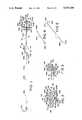
- FIG. 1shows a catheter and insertion tool according to the invention.
- FIG. 1Ashows an alternative embodiment of the insertion tool shown in FIG. 1.
- FIG. 1Bis an enlarged view of a portion of FIG. 1A.
- FIG. 2shows a locking mechanism of the invention in a partially extended configuration.
- FIG. 3shows the locking mechanism of FIG. 2 in a fully expanded configuration.
- FIG. 4shows a needle for use with the invention.
- FIG. 5shows a guide wire for use with the invention.
- FIG. 6shows an alternative embodiment to the apparatus of FIG. 1.
- FIG. 7shows a retaining ring for use with the invention.
- FIG. 8shows an alternative embodiment of the apparatus of FIG. 6, showing a detent mechanism.
- FIG. 9shows another alternative embodiment to the apparatus of FIG. 6, showing another detent mechanism.
- FIG. 9Ashows a releasing tool for releasing the locking mechanism of the invention.
- FIG. 10shows another alternative embodiment to the apparatus of FIG. 6.
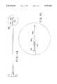
- FIG. 11is a detailed drawing, with dimensions in inches and angles in degrees, of a preferred embodiment of the invention.
- FIG. 11Ais a view like that of FIG. 11 of another embodiment of the invention.
- FIGS. 11B and 11Care close-up views of the areas designated in FIG. 11A by arcs 11B and 11C, respectively.
- FIG. 11Dis a close-up view of the forward portion of the device shown in FIG. 11A.
- FIG. 12is a sectional drawing taken along line 12--12 of FIG. 11.
- FIG. 13is a sectional drawing taken along line 13--13 of FIG. 11.
- FIG. 14shows an alternative embodiment to the apparatus of FIG. 1.
- FIG. 15shows the apparatus of FIG. 10 in use with a feeding catheter.
- FIG. 16is a top view of a portion of the apparatus of FIG. 15.
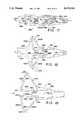
- FIGS. 17-22show various views and configurations of an alternative embodiment to the locking mechanism of the invention.
- FIGS. 23-24show an insertion tool for use with the embodiment of FIGS. 17-22.
- FIG. 1shows a gastrostomy feeding catheter 10 according to the invention, which is preferably of a hypoallergenic, biocompatible, flexible substance such as silicon.
- the catheter 10includes a proximal end 20 which is adapted for receiving medical apparatus in a conventional manner.
- a plug 30is carried on a flap 40, which is attached in a flexible or hinged fashion to the proximal end 20.
- the plug 30is adapted to fit snugly into a central bore 15 of the proximal end 20.
- the catheter 10also includes a distal end 50, and a locking mechanism or anchor 60 is attached, as shown in FIGS. 1-3.
- the mechanism 60is preferably formed of a rigid, biocompatible material such as polypropylene or the like.
- the mechanism 60is generally cylindrical in configuration, and includes a first end 70 which is provided with annular ridges or teeth 80, which are angled to the right from the point of view of FIGS. 1-3.
- the distal end 50 of the catheter 10has an inner diameter which closely conforms to the outer diameter of the first end 70.
- the distal end 50may be fused, glued, or otherwise joined to the first end 70.
- One manner of joining theseis to fit the distal end 50 tightly over the first end 70, as shown in FIG. 3, slightly distending the end 50 in doing so.
- the elasticity of the material from which the catheter 10 is formedcauses the end 50 to contract tightly against the ridges 80, thus forming a reliable connection between the catheter 10 and the mechanism 60.
- the mechanism 60also includes a second end 90, which is generally frustoconical or tapered in shape, and includes a bore 100. Disposed within the bore 100 is at least one, but preferably two, locking knobs 110, with a function to be described below.
- the second end 90is provided with lateral ports 120 and a terminal port 130, which are exit ports for fluid introduced into the catheter 10.
- the mechanism 60also includes a central portion 140 comprising legs 150, 160, 170 and 180.
- the first end 70, the second end 90, and the central portion 140are preferably formed in a unitary fashion.
- each leg 150-180is attached in a hinged fashion at hinges 190 to the first end 70, and is also attached in a hinged fashion at hinges 200 to the second end 90.
- Each legis also hinged in the middle, forming two branches for each leg, namely, branches 150A-B, 160A-B, 170A-B, and 180A-B.
- the branches 150A and 150Bare hinged together at a hinge 210, and likewise the branches of each of the legs 160, 170 and 180 are hinged at hinges 220, 230, and 240, respectively.
- the locking mechanism 60may be configured to be fully extended, such that the branches 150A, 160A, 170A and 180A are substantially collinear with the branches 150B, 160B, 170B and 180B, and are substantially parallel to one another.
- FIG. 2shows a partially extended configuration
- FIGS. 1 and 3show a completely expanded position, wherein branches 150A, 160A, 170A and 180A are substantially parallel to and adjacent the branches 150B, 160B, 170B and 180B, respectively.
- the legs 150-180are configured such that they are angled forwardly when the mechanism 60 is in its expanded configuration.
- a flexible, somewhat elastic membrane 105is fitted over the locking mechanism 60, and overlaps the distal end 50 in the region of the ridges 80, as shown in FIGS. 1 and 3.
- the membrane 105covers the legs 150-180, and also is tightly configured to match the outer diameter of the second end 90 of the locking mechanism 60.
- the membrane 105forms a fluid-tight seal with the catheter 10 and the end 90. Fluid passing through the bore 15, shown in FIG. 1, also passes the locking mechanism 60 and out through the ports 100 and 120 without any leakage between the membrane 105 and the catheter 10 or between the membrane 105 and the second end 90, thus forming a continuous fluid channel in the interior of the catheter 10 and the membrane 105 between the proximal end 20 and the second end 90.
- the elasticity and flexibility of the membrane 105are selected such that when the mechanism 60 is in the configuration shown in FIGS. 1 and 3, the membrane 105 contracts tightly against the mechanism 160.
- the mechanism 60may be repeatedly drawn into the configuration shown in FIGS. 2 and 3, respectively, by pulling or pushing on the first end 70 with respect to the second end 90, and each configuration is maintained until affirmative force is applied towards the other configuration
- the branches 150A-180Aare in the preferred embodiment slightly longer than the branches 150B-180B, and the branches are configured (as discussed in detail relative to FIG. 11 below) such that, when the locking mechanism 60 is in the expanded configuration, the branches will lie at somewhat less than a right angle to the catheter 10, as shown in FIG. 1.
- the mechanism 60is maintained in this configuration by the axially inward force exerted by the membrane 105 between the legs 150-180 and the distal end 50 of the catheter 10.
- both the expanded and collapsed (or collinear, extended) configurations of the mechanism 60are resting configurations. That is, there is no tool or force necessary to maintain these configurations; rather, they are stable configurations. This is unlike the apparatus and methods of conventional design, wherein distal end buttons have partially collapsed configurations, but only when a force is affirmatively applied thereto.
- FIG. 11shows a detailed drawing of a locking mechanism 700 which is an alternative to the embodiment of the locking mechanism 60 of FIG. 1, wherein the structure of the branches 150-180 is identical, but with slightly altered features in the collar of the mechanism.
- FIGS. 11A-11Dshow detailed drawings of a locking mechanism, also referred to by the numeral 700, which is substantially identical to the mechanism 60.
- reference to FIG. 11should be understood also to apply to FIGS. 11A-11D, although, as seen from an inspection of these figures, there are certain structural and design differences.
- the mechanism 700 shown in FIG. 11includes a shaft 710 and a collar 720.
- the mechanism 700includes four legs 150-180, as in the above-discussed embodiments, although only legs 160 and 170 are shown in FIG. 11.
- Each of the branches 150A-180Ais attached to the collar 720 and forms an angle 730 with respect thereto.
- this angle 730is approximately 42 degrees.
- this angleis preferably approximately 82 degrees.
- the angle Bis 100 degrees.
- angle 740is formed between each of the branches 150B-180B by the surfaces 810 at the forward ends of the branches 150B-180B, and the surfaces 820 formed on the forward end 750.
- angle 740is 100 degrees (which is the supplement of the angle 730) when the mechanism 700 is in its flat configuration, i.e. when the branches 150A-180A and the branches 150B-180B are substantially collinear to one another.
- angle 740is such that branches 150B-180B lean forwardly when the mechanism 700 is in its fully expanded configuration (as in FIG. 3), resulting, in this embodiment, in an 80 degree angle for angle A between the branches 150B-180B and a central axis 830 of the shaft 710.
- angles 730 and 740are usable, such as 82 degrees and 98 degrees, respectively, or other combinations of angles which result in a sufficient angle for the branches 150-180 when the locking mechanism is in its expanded configuration such that the mechanism will be held in place by the axially inward force of the surrounding membrane.
- angle 730should be less than 90 degrees and angle 740 should be greater than 90 degrees; and when the mechanism 700 is in its expanded configuration, angle A should be less than 90 degrees, while angle B should be greater than 90 degrees.
- the sum of angles A and Bwill be 180 degrees
- Branches 150A-180Aare joined to the collar 720 by means of interior hinges 760, and branches 150B-180B are joined to the forward end 750 by interior hinges 770.
- the hinges 760 and 770may be plastic membranes formed in a unitary fashion with the collar 720 and the branches 150A-180A, and with the branches 150B-180B and the forward end 750, respectively.
- a stop 780is disposed between each pair of branches 150A-150B, 160A-160B, 170A-170B, and 180A-180B.
- Each stop 780is joined to the adjacent branches by exterior hinge membranes 790 and 800, and may be formed in a unitary fashion with the respective branches.
- the stop 780is preferably triangular in shape, and abuts against the ends 782, 784, 786 and 788 of the branches 160A, 160B, 170A and 170B, respectively.
- the angles of the edges of the stop 780 and of the ends 782-788are such that, when the mechanism 700 (or 60) is in the configuration of FIG.
- each pair of branchesis in a parallel configuration; but the branches are prevented from sliding against one another by the stop 780, which exerts a binding force against each of the branches.
- any force on the mechanism 700 from, for example, the stomach wallis distributed by the stop 780 to the branches, and is further transmitted by the branches to the surface 820.
- the predetermined combination of anglesresults in such external forces actually causing the mechanism to seat even more tightly in its expanded configuration. The distribution of forces lowers the likelihood that a force at any particular point will cause failure or collapse of the mechanism.
- An insertion tool 250(shown in FIG. 1) is utilized with the invention, comprising a long, rigid, preferably metal rod 260, a handle 270, and a tip 280.
- the tip 280includes a frustoconical or tapered section 290, which is adapted in size and shape to closely match the shape of the bore 100 of the second end 90 of the locking mechanism 60.
- a groove 300runs parallel to the length of the tip 280 and extends to the end of the section 290, and includes an angled portion 310, which is preferably at substantially a right angle to the length of the tip 280, as shown in FIG. 1. Other angles than a right angle may be used for the portion 300, including acute angles.
- Another groove(not separately shown) is provided symmetrically opposite to the groove 300, and also includes an angled portion, such as angled portion 310.
- the disposition of the hinges 760, 770, 790 and 800, coupled with the presence of the insertion tool within the bore 715 of the shaft 710,ensures that the branches 150A-180A and 150B-180B can move only outwards.
- the branches 150A-180A and 150B-180Bbuckle outwardly; if it were not for the radial offset of the hinges, the branches might jam up against one another, without moving outwardly. Because of the tool 250 being within the mechanism 60, there is no chance that the branches will buckle inwardly against one another.
- the branchestake on their forwardly-angled configuration of FIG. 3, and the stops 780 prevent the branches 150A-180A from moving further relative to the branches 150B-180B.
- a forceis exerted by the membrane 105 in an inwardly axial direction against the legs 150-180, which keeps the mechanism 700 (or the mechanisms 60) in the expanded configuration, and provides high stability which is enhanced further by any pressure of the stomach wall against the branches 150A-180A.
- the outer diameter of the mechanism 60is independent of the number of branches or legs which it includes, and the expanded diameter is independent of the collapsed diameter.
- a retaining button or locking ring 320is configured to fit in a tight, frictional manner over the catheter 10.
- the locking ring 320includes a collar 330, a plurality of raised, radially disposed ridges 340, air vents 350 alternating with the ridges 340, and air gaps 360 formed between the ridges 340.
- the locking ring 320is utilized in a manner described below, and as further described in U.S. Pat. No. 4,666,433, which is incorporated herein by reference.
- the device as shown in FIGS. 1-3 and 7is utilized in the following manner.
- a needle 370 having a lumen 380(see FIG. 4) is inserted through the skin and into the stomach.
- a guide wire 390(shown in FIG. 5) is then inserted through the lumen 380.
- the guide wire 390includes a bight 400 at its distal end 410, and is preferably formed of a tightly coiled metal, brazed at its distal tip 430, to maintain the coiled configuration. Brazing may also be used to maintain the shape of the bight 400. Other means of maintaining the coiled configuration and the bight shape may be used, including adhesives, welds, or the like.
- the bight 400is flexible, as is the entire guide wire 390, such that it may be straightened out to be inserted through the lumen 380 and into the stomach. Once the distal end 410 of the guide wire 390 passes out of the tip of the lumen 380 and into the stomach, it returns to its bight-shaped configuration.
- the needle 370may be removed.
- the insertion tool 250is inserted through the bore 15 of the catheter 10, such that its tip 280 passes through the bore 100 of the locking mechanism second end 90.
- the tip 280passes into the bore 100, resistance is met thereto by the knobs 110 within the bore 100, and the insertion tool 250 is rotated until the grooves 300 align with the knobs 110, at which point the tip 280 may pass further into the bore 100, until the knobs 110 contact the right-angled portions 310.
- the insertion tool 250is then rotated (clockwise as viewed from left to right in FIG. 1), such that the knobs 110 are within the portions 310, and prevent further longitudinal movement of the insertion tool 250 relative to the locking mechanism 60.
- the insertion tool and gastrostomy catheter 10are then slid in tandem over the guide wire 390, a bore 440 (shown in part in FIG. 1) being provided through the center of the insertion tool 250 to accommodate the guide wire 390.
- the catheter 10is thereby inserted through the opening originally formed by the needle 370 and into the patient's stomach (or other area under treatment), with the rigidity of the tool 250 supporting the catheter during insertion, allowing it to be pushed through the opening made by the needle 370.
- the conical shapes of the tip 280 and of the end 90allow the insertion tool 250 and the catheter 10 to pass into the opening to the patient's stomach with minimal enlargement thereof, ensuring a tight fit for the catheter 10. This is further ensured by configuring the very end of the tip 280 outer diameter closely matches the diameter of the second end 90 at the point of contact, so that there is an essentially continuous and gradual increase in the diameter of the combined apparatus.
- the section 290 of the tip 280is extremely long and tapered, and is sharp as a standard cannula or needle at its distal end, such that the tool 250 may be used for initial insertion of the catheter, without the need for an extra needle and guide wire.
- the tool 250is still, in this embodiment, used for manipulating the mechanism 60.
- the locking mechanism 60When the locking mechanism 60 is in its fully extended position, it has an outer diameter which is substantially the same as the outer diameter of the catheter 10, such that the mechanism 60 provides minimal resistance to insertion of the catheter into the stomach. This avoids the necessity of creating a hole with a diameter larger than the gastrostomy catheter through the stomach wall to accommodate the locking mechanism.
- the catheter 10, being of a flexible, somewhat elastic materialis slightly stretched as the insertion tool is used to place the catheter within the stomach. Since the catheter has a larger diameter than that of the needle 370, the catheter 10 or catheter 510 enlarges the opening originally made with the needle 370. This results in a very tight fit with the opening, which reduces or eliminates the problem of gastric leakage. The fit of the catheter is made even tighter by the fact that it is stretched thin while it is being inserted, such that it reexpands upon release of the tension on it, filling the opening snugly.
- the guide wireis preferably long enough such that its proximal tip 420 extends out of the handle 270 when the insertion tool 250 and catheter 10 are in place.
- the guide wire 390may be removed once the tool 250 and catheter 10 are positioned, simply by pulling on its proximal tip 420.
- the operator of the devicepulls back on the insertion tool 250, which brings the locking mechanism 60 into the configuration shown in FIGS. 1 and 3. This is done by the operator holding his or her fingers against the skin, one on either side of the catheter 10, and lightly squeezing the catheter. The tool 250 is then pulled back, thus opening the mechanism 60 up while the fingers maintain the catheter in place.
- the operatorpulls outward on the catheter, to seat the mechanism 60 against the inner wall of the stomach. Then, the operator slides the locking ring 350 against the skin 450, such that the catheter 10 is maintained tightly in place by the locking mechanism 60 and the locking ring 320. Then, the insertion tool 250 is rotated counterclockwise, such that the grooves 300 align with the knobs 110, and the insertion tool 250 is then removed. At this point, the gastrostomy catheter 10 is fixed in place, and conventional medical apparatus may be attached to the proximal end 20 for enteral feeding, delivery of medications, or the like.
- the catheter 10When the catheter 10 is emplaced as described above, the patient's skin 450 will contact the ridges 340 of the locking ring 320, and the inner surface 460 of the patient's stomach will be adjacent the locking mechanism 60, as shown in simplified fashion in FIG. 1.
- the ring 320may be positioned for a tight fit by sliding it relative to the catheter 10. It is helpful to pull back on the catheter 10, thus stretching it slightly--due to opposing forces from the pulling force and the anchor (i.e. mechanism 60), respectively--and then sliding the button or locking ring 320 against the patient's skin. Tension on the catheter is then maintained between the ring 320 and the anchor 60, resulting in a firm clamping configuration against the stomach wall and the skin of the patient.
- the insertion tool 250is reinserted such that the knobs 110 are again slid into the grooves 300 and then into the portions 310, and the insertion tool 250 is pushed inwardly until the locking mechanism 60 takes on the fully extended position. The insertion tool is then removed, and the catheter 10 may then be withdrawn from the stomach.
- the catheterconstitutes a primary catheter, i.e. a catheter for initial insertion into the patient. It is customary, or may be necessary for health reasons, to replace the primary catheter after a period of time with a secondary catheter, which maintains access to the patient's stomach for continued treatment.
- FIG. 6Such a secondary catheter incorporating the present invention is shown in FIG. 6, wherein the locking mechanism 60 is as described above, but an insertion tool 470 having a blunt end 480 is used rather than the insertion tool 250.
- the tool 470need not be hollow, as with the tool 250.
- the end 480includes grooves 300 and portions 310, which coact with the knobs 110 (shown in FIG. 6) in the same fashion as described above relative to FIG. 1-3.
- the catheter 510 of this embodimentdiffers in several respects from the catheter 10, including that the locking mechanism includes a rounded or blunt distal end or tip 525.
- the tapered end 90 of the catheter 10 shown in FIG. 1is unnecessary in this embodiment, because the opening has already been formed in the patient. It is for this reason that both the end 480 and the end 525 are rounded or blunt.
- a retaining button 490is provided, and includes a relatively rigid, exteriorly threaded shaft 500.
- the catheter 510also includes a relatively rigid shaft 520 which is preferably formed in unitary fashion with the shaft 500.
- the shafts 500 and 520are in fact a continuous, generally cylindrical tube of moderately hard rubber or soft plastic, and are provided with circumferential grooves 522, as shown in FIG. 8.
- the total length of the shafts 500 and 520may be varied by varying the length of the overlap region 524, which is accomplished by either pushing the shaft 500 towards the shaft 520 to maximize the overlap 524, thus minimizing the total length of the shafts 500 and 520; or by pulling them apart, thus minimizing the overlap 524 and maximizing the total length.
- the shafts 500 and 520are maintained in their relative positions by the moderate stiffness of the material from which they are formed and by the grooves 522, which provide friction against relative longitudinal movement.
- the shafts 500 and 520may be provided with threads, such that their total length (and overlap) is governed by the degree to which they are threaded together.
- the button 490 in a preferred embodimentmay be of substantially the same design as the button 320.
- a one-way valve 530is carried by a rigid T-stem 540, which itself is carried tightly within the button 490.
- the T-stem 540may be provided with an annular flange 550, and the valve 530 includes a corresponding annular groove 560 for retention purposes.
- the valve 530is preferably formed of a flexible rubber, plastic, or other material, such that fluids may pass from left to right from the point of view of FIG. 6, but not from right to left.
- the rigidity of the shaft T-stem 540prevents accidental opening of the valve 530 due to pressure or squeezing of the catheter.
- the T-stem 540is removable, along with the valve 530, by pulling outwardly on the T-stem, which may be desired, for instance, for decompression of the peritoneal cavity.
- the valve 530is provided to compensate for the fact that the shaft 520 is made relatively short in this embodiment.
- the length of the catheter 10 between the proximal end 20 and the distal end 50is relatively long, such that, if fluids travel up the shaft thereof, they are prevented from exiting the proximal end 20 by back-pressure or head within the catheter.
- the valve 530is provided to keep such fluids from exiting the patient via the catheter 510.
- the design of the catheter 510is such that a wide variety of sizes of catheters may be made, with variations both in diameter and length; and this is also true for the catheter 10.
- the identical structure of the valve 530may be used in a larger-diameter catheter merely by enlarging the diameter of the valve itself.
- the sliding locking ring 320allows this longer proximal end of the catheter 10, whereas the nonsliding retaining button 490, shown in FIG. 6, causes the catheter 510 to be shorter because of the limiting factor of the distance of the button 490 from the locking mechanism 545.
- the catheter 510may be provided with an additional proximal length to the left of button 490, to provide the pressure or head necessary to keep fluids from flowing out of the stomach through the catheter 510.
- the valve 530may be dispensed with.
- the button 490is provided with a plug 570, which is attached in a hinged or otherwise flexible fashion to the main portion of the button 490, such as by means of a rubber flap 580.
- the plug 570fits snugly into the bore 960, and is provided with an annular groove 495 for interacting with an annular groove 495 within the bore 960, as shown in FIG. 10.
- the catheter 510is used in conjunction with the insertion tool 470 in much the same manner as the device described relative to FIG. 1 above. However, because the catheter 510 is a secondary catheter, the opening for access to the patient's stomach, i.e. the track or stoma, is already formed when the catheter 510 is put to use.
- the insertion tool 470is first inserted through the bore 590 of the catheter 510, for which purpose the plug 570 must be pulled out of the end of the button 490.
- the valve 530is removed by pulling the T-stem 540 out, and then the tool 470 is inserted so that the knobs 110 are positioned into the portions 310 via the grooves 300, as described relative to the first embodiment.
- the catheter 510is then inserted through the opening into the patient's stomach, and the locking mechanism 545 is pulled into its locking configuration, shown in FIGS. 3 and 6.
- the insertion tool 470is then removed, and the valve 530 is replaced along with the T-stem 540. Medications, nutrients or the like may then be provided through the catheter 510, and will exit through the lateral ports 120 and the terminal port 100.
- the shafts 500 and 520are preferably adjusted as described above such that the distance between the button 490 and the locking mechanism 60 is approximately the same distance as that between the outer layer of skin 450 and the inner wall of the stomach 460 (shown in FIG. 1), for a tight fit. As described below relative to FIGS. 8 and 9, this distance may be made adjustable so that a single design of catheter may accommodate a variety of different lengths. This is particularly important for gastrostomy applications, since it is desirable that the stomach is firmly pressed against the abdominal wall, so that the two heal together while the catheter is in place. Such healing is useful especially for long-term emplacement of feeding catheters; without it, stomach fluids may leak into the peritoneum, causing peritonitis and other complications.
- the necessary firmness of the pressure on the stomach and the abdominal wallis achieved in the present invention both by the adjustability of the apparatus and by the fact that the anchor of the invention is formed from a rigid material.
- FIG. 8shows an alternative embodiment to the gastrostomy catheter 510 shown in FIG. 6, incorporating a locking mechanism 615 which may be utilized either with the catheter 510 or the catheter 10.
- the catheter 600is identical to the catheter 510, except for the locking mechanism.
- catheter 600is a secondary catheter, for use after a primary catheter (such as catheter 10) has been removed.
- branches 150A-180Ainclude locking detents 150C-180C.
- branches 150B-180Binclude locking detents 150D-180D, which are configured to interlock with the detents 150C-180C. For instance, as shown in FIG. 8, detent 160C clips into detent 160D, and detent 170C clips into detent 170D.
- a single detentmay be utilized, or, as in FIG. 9, multiple detents may be utilized on the legs 150-180.
- the use of multiple detentshas the advantage of providing a tighter locking configuration, while the use of a single detent for each branch has the advantage of being easier to snap into and out of the locking configuration.
- FIG. 9Ashows a releasing tool 610 having a handle 620 and a shaft 630.
- the bore 15 of the catheter 10 (shown in FIG. 1) and the bore 515 of the catheter 510 (shown in FIG. 6)are rectangular in cross section, and closely match the shape of the shaft 630.
- the bore 100 (see FIG. 3) and the bore 535 of the tip 525 (see FIG. 6)are circular in cross section.
- the catheter 510 or the catheter 600When the catheter 10, the catheter 510 or the catheter 600 is in the expanded configuration (as shown in FIGS. 1, 6, and 8-9 respectively), and the releasing tool 620 is inserted into the bore (15, 515 or bore 555 of mechanism 615) of the catheter such that the shaft 630 passes through the bore, a forward end 640 of the shaft 630 contacts the forward end 750 at a region just distal of the hinges 770, at which region the cross-section of the interior of the mechanism goes from a rectangular cross-section to a circular cross-section.
- the rectangular cross-sectionaccommodates the tool 620 whereas the circular cross-section does not, so that pushing the tool 620 against the transition region forces branches 150B-180B away from branches 150A-180A. This returns the catheter to its non-locking position, such that it may be removed from the patient.
- the tool 610cannot be used to lock a mechanism (60, 545 or 615) in place, because the shaft 630 is configured such that it cannot engage the locking knobs 110 in such a manner as to pull back on the knobs.
- the tool 610is a discriminatory tool, which can disengage but not engage the locking mechanisms of the respective catheters. This is a useful tool for medical technicians or nurses who are qualified to remove, but are not authorized to emplace, gastrostomy catheters.
- FIG. 10A detailed view of an alternative embodiment of the catheter 510 shown in FIG. 6 appears in FIG. 10.
- the locking mechanism 655includes a collar 650 having external teeth 660.
- the catheter 645 of FIG. 10includes a shaft 670 having a forward end 680 with internal teeth 690 which interlock with the teeth 660.
- the locking mechanism 655may be moved closer to or farther from the retaining button 490, thus accommodating a variety of thicknesses of abdominal walls.
- FIG. 14shows an alternative embodiment of the primary cathether 10 FIG. 1, including a mechanism 840 similar to that of FIG. 10, surrounded by a membrane 850.
- the mechanism 840 in this embodimentincludes a collar 860 with exterior teeth 870 which interlock with interior teeth 880 of a shaft 890.
- the mechanism 840 shown in FIG. 14includes a tip 90 identical to the tip 90 shown in FIG. 1.
- FIG. 15shows the use of the catheter 645 shown in FIG. 10 in conjunction with a feeding adaptor 900, used for providing medicines, nutrients, or the like to the patient.
- FIG. 16shows a top view of the configuration of FIG. 15, with the button 490 having ridges 910 for spacing the button 490 from the skin of the patient. The ridges 910 are shown in dotted fashion in FIG. 16, and are disposed on the underside of the button 490.
- a coupling catheter port adaptor 920is attached to the adaptor 900 by means of a connecting arm 930 having forwardly-angled ridges 940.
- the adaptor 900is slightly elastic, and has an interior diameter which closely matches an exterior diameter of the exterior ridges 940. Thus, the adaptor 900 may be stretched slightly to fit over the ridges 940, and the forward angling of the ridges 940 keeps the catheter in place.
- the coupling adaptor 920includes a nipple 950 which fits tightly within the bore 960 of the button 490, and which includes an annular groove 925 which, like the groove 575 of the plug 570 (shown in FIG. 10), maintains the nipple 950 within the bore 960.
- the adaptor 900includes, at its proximal end 905, a med port 915 with a female luer connector for accommodating any standard male luer connector.
- the end 905also has a catheter port 905, which fits conventional feeding bag connectors.
- the adaptor 920which may take on a variety of sizes and configurations, may be used to couple a variety of catheters 900 with different sizes of catheters 645.
- the arm 930 and the nipple 950form a right angle, although other angles may be used.
- FIGS. 17-22show an alternative embodiment of the invention
- FIGS. 23-24show an applicator for use with the embodiment of the invention shown in FIGS. 17-21.
- a locking mechanism 970is provided, having legs 1010, 1020, 1030 and 1040. Note that only legs 1020 and 1030 are shown in FIGS. 17-20.
- leg 1010-1040includes a first branch and a second branch.
- leg 1010includes a first branch 1010A and second branch 1010B
- leg 1020includes a first branch 1020A and a second branch 1020B
- leg 1030includes a first branch 1030A and a second branch 1030B
- leg 1040includes a first branch 1040A and a second branch 1040B.
- the mechanism 970includes a tip 980 having internal ratchet teeth 990, as shown in FIGS. 17-20.
- Attached to the branches 1010A-1040Ais a collar 1000 having exterior ratchet teeth 1050.
- the collar 1000includes a locking knob 1070 in an interior bore 1080 thereof.
- a membrane 1060Carried in a sealed fashion rearwardly of the legs 1010-1040 is a membrane 1060, which is itself connected in a sealed fashion to a catheter 1090 as shown in FIG. 21.
- the tip 980includes a bore 1100 which is in communication with the bore 1080, which in turn is in communication with a lumen 1110 of the catheter 1090. Ports 1120 may be provided in the tip 970.
- the initial configuration of the mechanism 970, ready for insertion into the patient,is shown in FIG. 17.
- the mechanism 970is inserted into the opening into the stomach, as described above with respect to the earlier-discussed embodiments of the invention. This is accomplished by means of an insertion tool 1130 (shown in FIG. 23), which has a forward end 1140.
- the end 1140includes a longitudinal groove 1150 which includes a portion 1160 at an angle (preferably a right angle) with respect to the longitudinal portion of the groove 1150.
- the insertion toolhas a shaft 1180 with an interior, longitudinal bore, in which a shaft 1175 having an end 1170 is slidably carried. Attached to the shaft 1175 is a handle 1185, and attached to the shaft 1180 is a handle 1190. A stop 1195 may be provided on the tip 1170 to prevent the shaft 1180 from slipping off the end of the shaft 1175; a complet stroke of the shaft 1180 relative to the shaft 1180 is then defined by the distance between the handles 1185 and 1190 when the end 1140 abuts the stop 1195.
- the tip 1170is inserted into the bore 1100, and is twisted until the groove 1150 engages the locking knob 1070.
- the tool 1130may be twisted such that the locking knob 1070 is seated within the portion 1160. Then, the physician or operator of the mechanism retracts the forward end 1140 by pulling backwards on the handle 1190 (while holding the catheter so that the mechanism is not retracted), thus bringing the mechanism 970 into the position shown in FIGS. 18, 21 and 22.
- the relative lengths of the shaft 1175 and the shaft 1180are such that one complete longitudinal movement of the handle 1190 from its forwardmost position relative to the handle 1185 to its rearmost position, or one complete stroke as defined above, corresponds in distance to the difference in the configurations of FIGS. 17 and 18, respectively. That is, when the handle 1190 (and hence the forward end 1170 and the collar 1000) moved back one complete stroke, the mechanism 970 goes from the collapsed configuration of FIG. 17 to the expanded configuration of FIG. 18.
- the tool 1130is then once again twisted such that the locking button is situated within the groove 1150, and the tool 1130 is then withdrawn.
- the catheter 1190 and mechanism 970may be maintained in place by a retaining ring slid against the skin of the patient, as described above.
- the forward end 1140is again inserted into the bore 1080, and the locking knob 1070 is once again seated within the portion 1160.
- the userthen pulls back on the handle 1190 in complete stroke, such that the mechanism 970 takes on the intermediate configuration shown in FIG. 19.
- Another complete strokethen collapses the mechanism 970 to a collinear configuration, as shown in FIG. 20.
- the mechanism 970may be removed from the patient.
- the collar 1000is prevented from moving forwardly with respect to the tip 980, once the teeth have engaged one another.
- the mechanism 970is in the configuration shown in FIG. 18, it is firmly locked in place, providing a reliable anchor for the catheter 1090.
- the force of the abdominal wall against the membrane 1060 and the branches 1010A-1040Aworks to keep the mechanism in place. Once this force is removed, however (such as if the mechanism is pushed further into the stomach so that the abdominal wall no longer contacts the membrane 1060), the collar 1000 is not prevented from moving rearwardly with respect to the tip 980; and thus, the mechanism 970 may be collapsed as shown in FIG. 20 and described above. Therefore, in removing the mechanism 970 as described above, it is preferable to first separate the membrane 1060 from contact with the patient.
- Hinges 1200, 1210 and 1220are provided (see FIGS. 19 and 20), and are configured such that the mechanism 970 may take on each of the configurations shown in FIGS. 17-20.
- hinges 1210connect the collar 1100 with the branches 1010A-1040A, and are preferably thin membrane hinges dispose away from the bore 1080 (see FIG. 17) such that when collar 1000 is moved to the left from the point of view of FIG. 17, branches 1010A-1040A will be urged radially outward.
- hinges 1200are preferably thin membrane hinges, as shown in FIG. 17 and 20, connecting branches 1010A-1040A to branches 1010B-1040B, respectively.
- Hinges 1200are preferably disposed on the interior side of the respective branches, as shown in FIG. 20.
- hinges 1220are preferably membrane hinges formed on the outside of their respective connections between the branches 1010B-1040B and the tip 980, as shown in FIGS. 19 and 20. This is to assist the legs 1010-1040 in being urged outwardly when the collar 1000 is pulled to the left from the point of view of FIGS. 17-20.
- the method and apparatus of the inventionmay be used not only in the form of primary and secondary gastrostomy catheters, but may be used in any application where it is desired to place a catheter or other such device into a patient, to provide fluids, allow for insertion of endoscopic or fiber optic apparatus, and other treatments.
- the present inventionis especially useful where the pull procedure is not available, such as for use with certain organs or parts of the body where access can be had only from one direction.
Landscapes
- Health & Medical Sciences (AREA)
- Life Sciences & Earth Sciences (AREA)
- Animal Behavior & Ethology (AREA)
- General Health & Medical Sciences (AREA)
- Public Health (AREA)
- Veterinary Medicine (AREA)
- Heart & Thoracic Surgery (AREA)
- Biophysics (AREA)
- Engineering & Computer Science (AREA)
- Anesthesiology (AREA)
- Biomedical Technology (AREA)
- Pulmonology (AREA)
- Hematology (AREA)
- Gastroenterology & Hepatology (AREA)
- Media Introduction/Drainage Providing Device (AREA)
Abstract
Description
Claims (50)
Priority Applications (2)
| Application Number | Priority Date | Filing Date | Title |
|---|---|---|---|
| US07/311,685US5073166A (en) | 1989-02-15 | 1989-02-15 | Method and apparatus for emplacement of a gastrostomy catheter |
| PCT/US1991/008326WO1993008855A1 (en) | 1989-02-15 | 1991-11-06 | Method and apparatus for emplacement of a gastrostomy catheter |
Applications Claiming Priority (1)
| Application Number | Priority Date | Filing Date | Title |
|---|---|---|---|
| US07/311,685US5073166A (en) | 1989-02-15 | 1989-02-15 | Method and apparatus for emplacement of a gastrostomy catheter |
Publications (1)
| Publication Number | Publication Date |
|---|---|
| US5073166Atrue US5073166A (en) | 1991-12-17 |
Family
ID=23207995
Family Applications (1)
| Application Number | Title | Priority Date | Filing Date |
|---|---|---|---|
| US07/311,685Expired - LifetimeUS5073166A (en) | 1989-02-15 | 1989-02-15 | Method and apparatus for emplacement of a gastrostomy catheter |
Country Status (2)
| Country | Link |
|---|---|
| US (1) | US5073166A (en) |
| WO (1) | WO1993008855A1 (en) |
Cited By (181)
| Publication number | Priority date | Publication date | Assignee | Title |
|---|---|---|---|---|
| US5112347A (en)* | 1991-05-14 | 1992-05-12 | Taheri Syde A | Embolectomy catheter, and method of operating same |
| US5248302A (en)* | 1992-08-05 | 1993-09-28 | Biosearch Medical Products Inc. | Percutaneous obturatable internal anchoring device |
| WO1993019660A1 (en)* | 1992-04-03 | 1993-10-14 | Baylor College Of Medicine | Gene therapy using the intestine |
| US5259367A (en)* | 1991-10-25 | 1993-11-09 | Sandoz Ltd. | Devices and methods for placement of feeding tubes |
| US5267969A (en)* | 1992-10-08 | 1993-12-07 | Abbott Laboratories | External retaining device for feeding tube or the like |
| WO1994004214A1 (en)* | 1992-08-14 | 1994-03-03 | Wayne State University | Retaining apparatus and procedure for transseptal catheterization |
| WO1994015657A1 (en)* | 1993-01-13 | 1994-07-21 | Direct Trends International Ltd. | Apparatus and method for maintaining a tracheal stoma |
| USD350201S (en) | 1992-10-08 | 1994-08-30 | Abbott Laboratories | External retaining device for a feeding tube |
| USD350393S (en) | 1992-12-08 | 1994-09-06 | Teleflex, Inc. | Low profile gastrostomy catheter |
| US5354283A (en)* | 1994-01-07 | 1994-10-11 | Little Rapids Corporation | Trocar retention apparatus |
| US5356391A (en)* | 1992-06-22 | 1994-10-18 | Medical Innovations Corp. | Flexible retainer flange for gastrostomy tube and the method of installing it |
| US5374254A (en)* | 1990-11-29 | 1994-12-20 | Buma; Shelley J. | Catheters with adjustable external locking bolsters |
| US5403326A (en)* | 1993-02-01 | 1995-04-04 | The Regents Of The University Of California | Method for performing a gastric wrap of the esophagus for use in the treatment of esophageal reflux |
| US5443449A (en)* | 1991-03-01 | 1995-08-22 | Applied Medical Resources Corporation | Cholangiography catheter |
| US5458583A (en)* | 1993-01-07 | 1995-10-17 | Medical Innovations Corporation | Gastrostomy catheter system |
| US5460603A (en)* | 1993-04-08 | 1995-10-24 | Massachusetts Institute Of Technology | Method and apparatus for preventing back flow in gastroenterological feeding system |
| US5571116A (en)* | 1994-10-02 | 1996-11-05 | United States Surgical Corporation | Non-invasive treatment of gastroesophageal reflux disease |
| US5628746A (en)* | 1989-01-18 | 1997-05-13 | Applied Medical Resources Corporation | Dilatation catheter assembly with cutting element and method of using the same |
| US5702365A (en)* | 1992-09-08 | 1997-12-30 | King; Toby St. John | Daul-lumen catheter |
| US5718691A (en)* | 1994-02-28 | 1998-02-17 | Russo; Ronald D. | Gastrostomy feeding port with a positively sealing one-way entrance valve |
| US5720734A (en)* | 1994-02-28 | 1998-02-24 | Wilson-Cook Medical, Inc. | Gastrostomy feeding ports |
| WO1998015309A1 (en)* | 1996-10-07 | 1998-04-16 | Applied Medical Resources Corporation | Apparatus and method for surgically accessing a body cavity |
| WO1998018506A1 (en)* | 1996-10-25 | 1998-05-07 | Bousquet Gerald G | Transcutaneous access device |
| EP0824929A3 (en)* | 1996-08-23 | 1998-05-20 | Fresenius AG | Percutaneous eneteral feeding catheter |
| US5803925A (en)* | 1995-01-17 | 1998-09-08 | Allergan | IOL insertion apparatus with covalently bonded lubricant |
| US5810810A (en) | 1992-04-23 | 1998-09-22 | Scimed Life Systems, Inc. | Apparatus and method for sealing vascular punctures |
| US5830125A (en)* | 1993-08-12 | 1998-11-03 | Scribner-Browne Medical Design Incorporated | Catheter introducer with suture capability |
| US5853399A (en)* | 1995-05-26 | 1998-12-29 | Sasaki; Hiroshi | Medical instruments and systems for puncturing an organ |
| US5855569A (en)* | 1996-03-14 | 1999-01-05 | Fuji Photo Optical Co., Ltd. | Expandable anchor mechanism for use in endoscopic biopsy channel |
| US5857999A (en)* | 1995-05-05 | 1999-01-12 | Imagyn Medical Technologies, Inc. | Small diameter introducer for laparoscopic instruments |
| US5860960A (en)* | 1996-01-11 | 1999-01-19 | C. R. Bard, Inc. | Bolster for corporeal access tube assembly |
| US5861002A (en)* | 1991-10-18 | 1999-01-19 | Desai; Ashvin H. | Endoscopic surgical instrument |
| US5902285A (en)* | 1997-01-27 | 1999-05-11 | Novartis Nutrition Ag | Jejunal feeding tube |
| US5902282A (en)* | 1996-12-26 | 1999-05-11 | Johnson & Johnson Medical, Inc. | Step-down catheter |
| US5941855A (en)* | 1997-10-03 | 1999-08-24 | Applied Medical Technology, Inc. | Gastrostomy device package and method of assembly |
| US5942277A (en)* | 1996-07-10 | 1999-08-24 | Allergan | IOL insertion apparatus and method for making and using same |
| USD418220S (en)* | 1998-03-26 | 1999-12-28 | Applied Medical Technology, Inc. | Low profile balloon feeding device |
| US6036673A (en)* | 1996-01-11 | 2000-03-14 | C. R. Bard, Inc. | Bolster for corporeal access tube assembly |
| US6039714A (en)* | 1998-05-12 | 2000-03-21 | Novartis Nutrition Ag | Collapsible retention bolster for gastrostomy and other ostomy tubes |
| US6063085A (en) | 1992-04-23 | 2000-05-16 | Scimed Life Systems, Inc. | Apparatus and method for sealing vascular punctures |
| US6077243A (en)* | 1996-01-11 | 2000-06-20 | C.R. Bard, Inc. | Retention balloon for a corporeal access tube assembly |
| US6083230A (en)* | 1997-07-30 | 2000-07-04 | Allergan | Method for making IOL insertion apparatus |
| WO2000061016A1 (en)* | 1999-04-09 | 2000-10-19 | Karl Storz Gmbh & Co. Kg | Device for producing a transcutaneous access to a hollow viscus in the interior of the body |
| US6165156A (en)* | 1996-04-02 | 2000-12-26 | Avitar, Inc. | Device and method for fastening a catheter |
| US6231591B1 (en) | 1991-10-18 | 2001-05-15 | 2000 Injectx, Inc. | Method of localized fluid therapy |
| US6248111B1 (en) | 1999-08-06 | 2001-06-19 | Allergan Sales, Inc. | IOL insertion apparatus and methods for using same |
| US6283975B1 (en) | 1996-07-10 | 2001-09-04 | Allergan Sales, Inc. | IOL insertion apparatus and method for making and using same |
| WO2001037915A3 (en)* | 1999-11-25 | 2002-03-14 | Ssl Int Plc | Medical device |
| US6364858B1 (en) | 1998-03-31 | 2002-04-02 | Applied Medical Research, Inc. | Collapsible internal bolster for gastrostomy device |
| US6461296B1 (en)* | 1998-06-26 | 2002-10-08 | 2000 Injectx, Inc. | Method and apparatus for delivery of genes, enzymes and biological agents to tissue cells |
| US20030073908A1 (en)* | 1996-04-26 | 2003-04-17 | 2000 Injectx, Inc. | Method and apparatus for delivery of genes, enzymes and biological agents to tissue cells |
| US6579254B1 (en)* | 2000-06-19 | 2003-06-17 | Portex, Inc. | Medication adapter and method for use thereof |
| US20030139703A1 (en)* | 2000-12-14 | 2003-07-24 | Jeffrey Burkett | Tube device for feeding and method for the same |
| US20030225369A1 (en)* | 2002-05-31 | 2003-12-04 | Kimberly-Clark Worldwide, Inc. | Low profile transpyloric jejunostomy system |
| WO2003101519A1 (en)* | 2002-05-31 | 2003-12-11 | Kimberly-Clark Worldwide, Inc. | Low profile transplyoric jejunostomy system |
| US20040002647A1 (en)* | 1991-10-18 | 2004-01-01 | Ashvin Desai | Gel injection treatment of body parts |
| US20040006344A1 (en)* | 2002-07-02 | 2004-01-08 | Nguyen Thanh Van | Expandable percutaneous sheath |
| WO2004030722A3 (en)* | 2002-10-02 | 2004-06-17 | Civco Medical Instr Corp | Catheter including non-inflatable expandable elements |
| US20040171988A1 (en)* | 2002-03-08 | 2004-09-02 | Pierino Moretti | Combine needle and dilator device for central venous and arterial catheterization |
| US20040176788A1 (en)* | 2003-03-07 | 2004-09-09 | Nmt Medical, Inc. | Vacuum attachment system |
| US20040186349A1 (en)* | 2002-12-24 | 2004-09-23 | Usgi Medical Corp. | Apparatus and methods for achieving endoluminal access |
| US20040254545A1 (en)* | 2003-06-16 | 2004-12-16 | Rider Dean Loller | Method and apparatus for extending feeding tube longevity |
| USD500133S1 (en) | 2003-08-06 | 2004-12-21 | Kimberly-Clarke Worldwide, Inc. | Bolster |
| USD500132S1 (en) | 2003-08-06 | 2004-12-21 | Kimberly-Clark Worldwide, Inc. | Bolster |
| USD500552S1 (en) | 2003-08-06 | 2005-01-04 | Kimberly-Clark Worldwide, Inc. | Bolster |
| USD500853S1 (en) | 2003-08-06 | 2005-01-11 | Kimberly-Clarke Worldwide, Inc. | Bolster |
| US20050033268A1 (en)* | 2003-08-06 | 2005-02-10 | Kimberly-Clark Worldwide, Inc. | Connector with protrusion adapted for interconnection with second member |
| US20050033269A1 (en)* | 2003-08-06 | 2005-02-10 | Kimberly-Clark Worldwide, Inc. | Ferrule and enteral tube incorporating a ferrule |
| WO2005011463A2 (en) | 2003-07-01 | 2005-02-10 | Usgi Medical Inc. | Methods and apparatus for gastric reduction |
| US20050075605A1 (en)* | 1999-04-16 | 2005-04-07 | Lyon Thomas R. | Clear view cannula |
| US20050085771A1 (en)* | 1999-04-16 | 2005-04-21 | Lyon Thomas R. | Clear view cannula |
| US20050154357A1 (en)* | 2004-01-13 | 2005-07-14 | Pinel Lloyd J. | Controlled gastric bolus feeding device |
| EP1161273A4 (en)* | 1999-02-24 | 2005-08-17 | Sherwood Serv Ag | Securing device for a low profile gastrostomy tube |
| US6939361B1 (en) | 1999-09-22 | 2005-09-06 | Nmt Medical, Inc. | Guidewire for a free standing intervascular device having an integral stop mechanism |
| US20050240141A1 (en)* | 2004-04-26 | 2005-10-27 | Peter Aliski | Stent kidney curl improvements |
| US20050240280A1 (en)* | 2004-04-26 | 2005-10-27 | Peter Aliski | Ureteral stent |
| US20050240277A1 (en)* | 2004-04-26 | 2005-10-27 | Peter Aliski | Stent with flexible elements |
| US20050240278A1 (en)* | 2004-04-26 | 2005-10-27 | Peter Aliski | Stent improvements |
| US20050255039A1 (en)* | 1998-06-26 | 2005-11-17 | Pro Surg, Inc., A California Corporation | Gel injection treatment of breast, fibroids & endometrial ablation |
| US7066914B2 (en) | 2000-07-12 | 2006-06-27 | Bird Products Corporation | Catheter having a tip with an elongated collar |
| US7070587B2 (en) | 1999-02-24 | 2006-07-04 | Sherwood Services Ag | Securing device for a low profile gastrostomy tube having an inflatable balloon |
| US20060167406A1 (en)* | 2005-01-26 | 2006-07-27 | Radius International Ltd. Partnership | Catheter |
| WO2006111416A1 (en)* | 2005-04-21 | 2006-10-26 | Covidien Ag | Intracorporeal indwelling equipment |
| US20060270989A1 (en)* | 2005-05-27 | 2006-11-30 | Mcmichael Donald J | Gastric fastening system |
| US20060270993A1 (en)* | 2005-05-27 | 2006-11-30 | Mcmichael Donald J | Clamp for flexible tube |
| US20060287666A1 (en)* | 2005-06-15 | 2006-12-21 | Usgi Medical Inc. | Apparatus and methods for endoluminal advancement |
| US7156827B2 (en) | 2000-06-19 | 2007-01-02 | Smiths Medical Asd, Inc. | Adapter for localized treatment through a tracheal tube and method for use thereof |
| US20070088258A1 (en)* | 2005-10-13 | 2007-04-19 | Tyco Healthcare Group, Lp | Trocar anchor |
| US7226466B2 (en) | 2001-09-06 | 2007-06-05 | Nmt Medical, Inc. | Flexible delivery system |
| US20070149850A1 (en)* | 2005-12-22 | 2007-06-28 | Spivey James T | Endoscope endcap attachment tool |
| US20070219500A1 (en)* | 2006-01-12 | 2007-09-20 | Wright Clifford A | Universal catheter securement device |
| EP1836980A1 (en)* | 2006-03-22 | 2007-09-26 | Ethicon Endo-Surgery, Inc. | Intubation device for enteral feeding |
| US20070225647A1 (en)* | 2006-03-23 | 2007-09-27 | Luther Ronald B | Flush entrance hemostasis valve with unobstructed passageway |
| US20070233005A1 (en)* | 2006-04-03 | 2007-10-04 | Mcmichael Donald J | Surgical fastening tool |
| US20070239171A1 (en)* | 2006-03-30 | 2007-10-11 | Ethicon Endo-Surgery, Inc. | Medical snaring device |
| US20070239137A1 (en)* | 2006-03-30 | 2007-10-11 | Ethicon Endo-Surgery, Inc. | Intubation device for colonic decompression |
| US20070265617A1 (en)* | 2006-05-15 | 2007-11-15 | Applied Medical Resources Corporation | Dilation catheter assembly with bipolar cutting element |
| US20070287962A1 (en)* | 2004-04-30 | 2007-12-13 | Nippon Sherwood Medical Industries, Ltd. | Gastrostomy Tube Extension Device |
| USD561329S1 (en) | 2006-10-04 | 2008-02-05 | Kimberly-Clark Worldwide, Inc. | Low profile transpyloric jejunostomy catheter |
| US20080058730A1 (en)* | 2006-08-31 | 2008-03-06 | Cook Incorporated | Rotationally actuated fixation mechanism |
| US20080077043A1 (en)* | 2006-08-25 | 2008-03-27 | Manu Malbrain | Enteral feeding catheter and apparatus for determining the intra-abdominal pressure of a patient |
| US20080097491A1 (en)* | 2006-08-28 | 2008-04-24 | Fred Gobel | Tissue to tissue anchoring device and method of using the same |
| US20080121553A1 (en)* | 2006-08-28 | 2008-05-29 | Fred Gobel | Percutaneous gastrointestinal anchoring kit |
| US7416554B2 (en) | 2002-12-11 | 2008-08-26 | Usgi Medical Inc | Apparatus and methods for forming and securing gastrointestinal tissue folds |
| US20080208208A1 (en)* | 2004-04-30 | 2008-08-28 | Sherwood Services Ag | Gastrostomy Tube Extension Device |
| US7473266B2 (en) | 2003-03-14 | 2009-01-06 | Nmt Medical, Inc. | Collet-based delivery system |
| US7549424B2 (en) | 1991-10-18 | 2009-06-23 | Pro Surg, Inc. | Method and apparatus for tissue treatment with laser and electromagnetic radiation |
| USRE40863E1 (en)* | 1992-04-23 | 2009-07-21 | Boston Scientific Scimed, Inc. | Apparatus and method for sealing vascular punctures |
| US20090209972A1 (en)* | 2008-02-20 | 2009-08-20 | Loushin Michael K H | Ventilation Device and Insertion System Therefor |
| US20090216186A1 (en)* | 2008-02-26 | 2009-08-27 | Nath Iyunni Venkata Sesha Sayi | Feeding tube |
| US7591803B2 (en) | 1997-05-29 | 2009-09-22 | Venetec International, Inc. | Medical line anchoring system |
| JP2009225998A (en)* | 2008-03-24 | 2009-10-08 | Sumitomo Bakelite Co Ltd | Connector |
| US7618426B2 (en) | 2002-12-11 | 2009-11-17 | Usgi Medical, Inc. | Apparatus and methods for forming gastrointestinal tissue approximations |
| US7648492B2 (en) | 2002-10-01 | 2010-01-19 | Venetec International, Inc. | Catheter securement device |
| US7658747B2 (en) | 2003-03-12 | 2010-02-09 | Nmt Medical, Inc. | Medical device for manipulation of a medical implant |
| US7666203B2 (en) | 2003-11-06 | 2010-02-23 | Nmt Medical, Inc. | Transseptal puncture apparatus |
| US7678132B2 (en) | 2001-09-06 | 2010-03-16 | Ovalis, Inc. | Systems and methods for treating septal defects |
| US7691112B2 (en) | 2003-09-11 | 2010-04-06 | Nmt Medical, Inc. | Devices, systems, and methods for suturing tissue |
| US7740640B2 (en) | 2001-09-06 | 2010-06-22 | Ovalis, Inc. | Clip apparatus for closing septal defects and methods of use |
| US20100168569A1 (en)* | 2008-12-30 | 2010-07-01 | Sliwa John W | Image-guided ablation system and method for monitoring an ablation procedure |
| US7803137B2 (en) | 2006-03-22 | 2010-09-28 | Ethicon Endo-Surgery, Inc. | Intubation system for use with an endoscope |
| US7806873B2 (en) | 2006-07-13 | 2010-10-05 | Venetec International, Inc. | Intravenous securement device with adhesively interconnected anchoring component and permeable adhesive strip |
| US7846179B2 (en) | 2005-09-01 | 2010-12-07 | Ovalis, Inc. | Suture-based systems and methods for treating septal defects |
| ITMO20090169A1 (en)* | 2009-06-26 | 2010-12-27 | De Magistris Ludovico Ambrosi | ENTERAL NUTRITION DEVICE |
| US7879013B2 (en) | 2005-12-21 | 2011-02-01 | Venetec International, Inc. | Intravenous catheter anchoring device |
| US20110028904A1 (en)* | 2009-07-30 | 2011-02-03 | Tyco Healthcare Group Lp | Stylet and Catheter Set |
| US20110034775A1 (en)* | 2009-02-25 | 2011-02-10 | Lozman Philip R | Surgical Retention Port and Method of Use |
| US7892203B2 (en) | 2004-09-09 | 2011-02-22 | Onset Medical Corporation | Expandable transluminal sheath |
| US7942884B2 (en) | 2002-12-11 | 2011-05-17 | Usgi Medical, Inc. | Methods for reduction of a gastric lumen |
| US7942898B2 (en) | 2002-12-11 | 2011-05-17 | Usgi Medical, Inc. | Delivery systems and methods for gastric reduction |
| US7955340B2 (en) | 1999-06-25 | 2011-06-07 | Usgi Medical, Inc. | Apparatus and methods for forming and securing gastrointestinal tissue folds |
| US7976518B2 (en) | 2005-01-13 | 2011-07-12 | Corpak Medsystems, Inc. | Tubing assembly and signal generator placement control device and method for use with catheter guidance systems |
| US7988690B2 (en) | 2004-01-30 | 2011-08-02 | W.L. Gore & Associates, Inc. | Welding systems useful for closure of cardiac openings |
| US8052649B2 (en) | 2005-09-19 | 2011-11-08 | Venetec International, Inc. | Medical tubing securement assembly and methods of use |
| US8052648B2 (en) | 2005-12-21 | 2011-11-08 | Venetec International, Inc. | Intravenous catheter anchoring device |
| US8070826B2 (en) | 2001-09-07 | 2011-12-06 | Ovalis, Inc. | Needle apparatus for closing septal defects and methods for using such apparatus |
| US8162898B1 (en) | 2005-04-18 | 2012-04-24 | Venetec International, Inc. | Venipuncture base plate assembly and method of using same |
| US8257394B2 (en) | 2004-05-07 | 2012-09-04 | Usgi Medical, Inc. | Apparatus and methods for positioning and securing anchors |
| JP2012176097A (en)* | 2011-02-25 | 2012-09-13 | Nihon Covidien Kk | Fistula catheter extender and catheter set having the extender |
| JP2012192182A (en)* | 2011-03-14 | 2012-10-11 | C R Bard Inc | Biased internal bolster for medical device |
| US8292910B2 (en) | 2003-11-06 | 2012-10-23 | Pressure Products Medical Supplies, Inc. | Transseptal puncture apparatus |
| WO2012106200A3 (en)* | 2011-01-28 | 2012-12-20 | Covidien Lp | Fistula catheter |
| US8366706B2 (en) | 2007-08-15 | 2013-02-05 | Cardiodex, Ltd. | Systems and methods for puncture closure |
| US8372072B2 (en) | 2003-02-04 | 2013-02-12 | Cardiodex Ltd. | Methods and apparatus for hemostasis following arterial catheterization |
| US8435236B2 (en) | 2004-11-22 | 2013-05-07 | Cardiodex, Ltd. | Techniques for heat-treating varicose veins |
| US8574240B2 (en) | 2011-01-07 | 2013-11-05 | Preceptis Medical, Inc. | Stabilization system and aspiration device with protected cutting edge |
| US8579936B2 (en) | 2005-07-05 | 2013-11-12 | ProMed, Inc. | Centering of delivery devices with respect to a septal defect |
| US8597277B2 (en) | 2004-09-09 | 2013-12-03 | Onset Medical Corporation | Expandable transluminal sheath |
| US20140066905A1 (en)* | 2012-08-29 | 2014-03-06 | Sayco Pty. Ltd. | Catheter Grip and Catheter Assembly |
| US8715244B2 (en) | 2009-07-07 | 2014-05-06 | C. R. Bard, Inc. | Extensible internal bolster for a medical device |
| US8726909B2 (en) | 2006-01-27 | 2014-05-20 | Usgi Medical, Inc. | Methods and apparatus for revision of obesity procedures |
| US20140187939A1 (en)* | 2012-10-10 | 2014-07-03 | Olympus Medical Systems Corp. | Treatment instrument |
| US8821392B2 (en) | 2009-02-25 | 2014-09-02 | Joint Product Solutions, Llc | Surgical retention port and method of use |
| US8834370B2 (en) | 2011-12-15 | 2014-09-16 | Cook Medical Technologies Llc | Ultrasonic percutaneous enteral feeding tube |
| WO2014164277A1 (en)* | 2013-03-12 | 2014-10-09 | University Of Florida Research Foundation, Inc. | Devices and methods for securing an anti-leak feeding tube for gastric and/or intestinal use |
| US8870916B2 (en) | 2006-07-07 | 2014-10-28 | USGI Medical, Inc | Low profile tissue anchors, tissue anchor systems, and methods for their delivery and use |
| US9028441B2 (en) | 2011-09-08 | 2015-05-12 | Corpak Medsystems, Inc. | Apparatus and method used with guidance system for feeding and suctioning |
| US9039661B2 (en) | 2011-05-24 | 2015-05-26 | Fresenius Kabi Deutschland Gmbh | Tube for the enteral feeding of a patient |
| WO2015103094A1 (en)* | 2013-12-30 | 2015-07-09 | H. Lee Moffitt Cancer Center And Research Institute, Inc. | Locking brakes for enteral feeding tube retention member |
| US20150196730A1 (en)* | 2012-07-23 | 2015-07-16 | University Of Utah Research Foundation | Indwelling urinary catheter |
| US9138560B2 (en) | 2006-01-12 | 2015-09-22 | Venetec International, Inc. | Universal catheter securement device |
| US9211234B2 (en) | 2010-09-27 | 2015-12-15 | Avent, Inc. | Configurable percutaneous endoscopic gastrostomy tube |
| US9241735B2 (en) | 2003-12-05 | 2016-01-26 | Onset Medical Corporation | Expandable percutaneous sheath |
| US20160143816A1 (en)* | 2013-06-20 | 2016-05-26 | Hadasit Medical Research Services And Development Ltd. | Devices and methods for percutaneous endoscopic gastrostomy and other ostomy procedures |
| US9370448B2 (en) | 2012-06-15 | 2016-06-21 | Preceptis Medical, Inc. | Insertion system for deploying a ventilation device |
| US9468740B2 (en) | 2000-03-10 | 2016-10-18 | Venetec International, Inc. | Medical anchoring system |
| US9480821B2 (en) | 2008-06-30 | 2016-11-01 | Venetec International, Inc. | Anchoring system for a medical article |
| US9642987B2 (en) | 2005-08-31 | 2017-05-09 | C.R. Bard, Inc. | Anchoring system for a catheter |
| US9682224B2 (en) | 2004-06-29 | 2017-06-20 | C. R. Bard, Inc. | Method and systems for providing fluid communication with a gastrostomy tube |
| US9895514B2 (en) | 2014-01-27 | 2018-02-20 | Maddoc Medical Products, Inc. | Medical device securement system and method |
| US10322262B2 (en) | 2009-05-21 | 2019-06-18 | C. R. Bard, Inc. | Medical device securement system |
| US10426708B2 (en) | 2014-12-23 | 2019-10-01 | Fidmi Medical Ltd. | Devices and methods for percutaneous endoscopic gastronomy and other ostomy procedures |
| US10537714B2 (en) | 2009-11-11 | 2020-01-21 | Venetec International, Inc. | Stabilizing device for an extension set |
| WO2020113159A1 (en)* | 2018-11-30 | 2020-06-04 | Quick Tube Medical, Llc | Method and apparatus for treating tension pneumothorax using a rapid deployment chest port |
| US10702304B2 (en) | 2014-12-23 | 2020-07-07 | Fidmi Medical Ltd. | Devices and methods for ports to living tissue and/or lumens and related procedures |
| US10729887B2 (en) | 2013-03-15 | 2020-08-04 | C. R. Bard, Inc. | Securement device having an integral strap and dressing |
| US20200397667A1 (en)* | 2018-02-14 | 2020-12-24 | Cornell University | Self collapsing feeding tube with cleaning mechanism |
| US20230102684A1 (en)* | 2020-06-04 | 2023-03-30 | Quick Tube Medical, Llc | Method and apparatus for treating tension pneumothorax using a rapid deployment chest port |
| US11793544B2 (en) | 2016-06-29 | 2023-10-24 | Fidmi Medical Ltd. | Measuring device |
| US11844913B2 (en) | 2012-03-23 | 2023-12-19 | Boston Scientific Medical Device Limited | Transseptal puncture apparatus and method for using the same |
| US12059536B2 (en) | 2019-02-01 | 2024-08-13 | Becton, Dickinson And Company | Stabilization device, system, and methods thereof for integrated catheters |
Citations (9)
| Publication number | Priority date | Publication date | Assignee | Title |
|---|---|---|---|---|
| US1969831A (en)* | 1934-04-19 | 1934-08-14 | Williams Alonzo Jedson | Syringe for use by veterinaries |
| US3713447A (en)* | 1971-08-16 | 1973-01-30 | E Adair | Suprapubic shunt |
| US4069826A (en)* | 1976-09-03 | 1978-01-24 | Barlow Mfg. Corporation | Surgical tube adapter clamp |
| US4393873A (en)* | 1980-03-10 | 1983-07-19 | Nawash Michael S | Gastrostomy and other percutaneous transport tubes |
| US4627838A (en)* | 1983-12-09 | 1986-12-09 | Bard Limited | Stylet actuated winged catheter |
| US4655752A (en)* | 1983-10-24 | 1987-04-07 | Acufex Microsurgical, Inc. | Surgical cannula |
| US4666433A (en)* | 1984-11-05 | 1987-05-19 | Medical Innovations Corporation | Gastrostomy feeding device |
| US4685901A (en)* | 1984-11-05 | 1987-08-11 | Medical Innovations Corporation | Gastro-jejunal feeding device |
| US4701163A (en)* | 1984-11-05 | 1987-10-20 | Medical Innovations Corporation | Gastrostomy feeding device |
- 1989
- 1989-02-15USUS07/311,685patent/US5073166A/ennot_activeExpired - Lifetime
- 1991
- 1991-11-06WOPCT/US1991/008326patent/WO1993008855A1/enactiveApplication Filing
Patent Citations (9)
| Publication number | Priority date | Publication date | Assignee | Title |
|---|---|---|---|---|
| US1969831A (en)* | 1934-04-19 | 1934-08-14 | Williams Alonzo Jedson | Syringe for use by veterinaries |
| US3713447A (en)* | 1971-08-16 | 1973-01-30 | E Adair | Suprapubic shunt |
| US4069826A (en)* | 1976-09-03 | 1978-01-24 | Barlow Mfg. Corporation | Surgical tube adapter clamp |
| US4393873A (en)* | 1980-03-10 | 1983-07-19 | Nawash Michael S | Gastrostomy and other percutaneous transport tubes |
| US4655752A (en)* | 1983-10-24 | 1987-04-07 | Acufex Microsurgical, Inc. | Surgical cannula |
| US4627838A (en)* | 1983-12-09 | 1986-12-09 | Bard Limited | Stylet actuated winged catheter |
| US4666433A (en)* | 1984-11-05 | 1987-05-19 | Medical Innovations Corporation | Gastrostomy feeding device |
| US4685901A (en)* | 1984-11-05 | 1987-08-11 | Medical Innovations Corporation | Gastro-jejunal feeding device |
| US4701163A (en)* | 1984-11-05 | 1987-10-20 | Medical Innovations Corporation | Gastrostomy feeding device |
Non-Patent Citations (6)
| Title |
|---|
| Miller et al., (1988) Gastrointestinal Endoscopy 34(4):339 342.* |
| Miller et al., (1988) Gastrointestinal Endoscopy 34(4):339-342. |
| Russell et al., (1984) American Journal of Surgery 148:132 137.* |
| Russell et al., (1984) American Journal of Surgery 148:132-137. |
| Techniques of Percutaneous Gastrostomy, edited by Jeffrey L. Ponsky, M. C., published by Igaku Shoin, 1988, pp. 1 171.* |
| Techniques of Percutaneous Gastrostomy, edited by Jeffrey L. Ponsky, M. C., published by Igaku-Shoin, 1988, pp. 1-171. |
Cited By (295)
| Publication number | Priority date | Publication date | Assignee | Title |
|---|---|---|---|---|
| US5628746A (en)* | 1989-01-18 | 1997-05-13 | Applied Medical Resources Corporation | Dilatation catheter assembly with cutting element and method of using the same |
| US5374254A (en)* | 1990-11-29 | 1994-12-20 | Buma; Shelley J. | Catheters with adjustable external locking bolsters |
| US5443449A (en)* | 1991-03-01 | 1995-08-22 | Applied Medical Resources Corporation | Cholangiography catheter |
| US5112347A (en)* | 1991-05-14 | 1992-05-12 | Taheri Syde A | Embolectomy catheter, and method of operating same |
| US7549424B2 (en) | 1991-10-18 | 2009-06-23 | Pro Surg, Inc. | Method and apparatus for tissue treatment with laser and electromagnetic radiation |
| US6231591B1 (en) | 1991-10-18 | 2001-05-15 | 2000 Injectx, Inc. | Method of localized fluid therapy |
| US20040002647A1 (en)* | 1991-10-18 | 2004-01-01 | Ashvin Desai | Gel injection treatment of body parts |
| US5861002A (en)* | 1991-10-18 | 1999-01-19 | Desai; Ashvin H. | Endoscopic surgical instrument |
| US5259367A (en)* | 1991-10-25 | 1993-11-09 | Sandoz Ltd. | Devices and methods for placement of feeding tubes |
| US5821235A (en)* | 1992-04-03 | 1998-10-13 | Baylor College Of Medicine | Gene therapy using the intestine |
| WO1993019660A1 (en)* | 1992-04-03 | 1993-10-14 | Baylor College Of Medicine | Gene therapy using the intestine |
| USRE40863E1 (en)* | 1992-04-23 | 2009-07-21 | Boston Scientific Scimed, Inc. | Apparatus and method for sealing vascular punctures |
| US5810810A (en) | 1992-04-23 | 1998-09-22 | Scimed Life Systems, Inc. | Apparatus and method for sealing vascular punctures |
| US6063085A (en) | 1992-04-23 | 2000-05-16 | Scimed Life Systems, Inc. | Apparatus and method for sealing vascular punctures |
| US5356391A (en)* | 1992-06-22 | 1994-10-18 | Medical Innovations Corp. | Flexible retainer flange for gastrostomy tube and the method of installing it |
| US5248302A (en)* | 1992-08-05 | 1993-09-28 | Biosearch Medical Products Inc. | Percutaneous obturatable internal anchoring device |
| WO1994004214A1 (en)* | 1992-08-14 | 1994-03-03 | Wayne State University | Retaining apparatus and procedure for transseptal catheterization |
| US5312341A (en)* | 1992-08-14 | 1994-05-17 | Wayne State University | Retaining apparatus and procedure for transseptal catheterization |
| US5702365A (en)* | 1992-09-08 | 1997-12-30 | King; Toby St. John | Daul-lumen catheter |
| USD350201S (en) | 1992-10-08 | 1994-08-30 | Abbott Laboratories | External retaining device for a feeding tube |
| US5267969A (en)* | 1992-10-08 | 1993-12-07 | Abbott Laboratories | External retaining device for feeding tube or the like |
| USD350393S (en) | 1992-12-08 | 1994-09-06 | Teleflex, Inc. | Low profile gastrostomy catheter |
| US5458583A (en)* | 1993-01-07 | 1995-10-17 | Medical Innovations Corporation | Gastrostomy catheter system |
| WO1994015657A1 (en)* | 1993-01-13 | 1994-07-21 | Direct Trends International Ltd. | Apparatus and method for maintaining a tracheal stoma |
| US5403326A (en)* | 1993-02-01 | 1995-04-04 | The Regents Of The University Of California | Method for performing a gastric wrap of the esophagus for use in the treatment of esophageal reflux |
| US5460603A (en)* | 1993-04-08 | 1995-10-24 | Massachusetts Institute Of Technology | Method and apparatus for preventing back flow in gastroenterological feeding system |
| US5830125A (en)* | 1993-08-12 | 1998-11-03 | Scribner-Browne Medical Design Incorporated | Catheter introducer with suture capability |
| US5354283A (en)* | 1994-01-07 | 1994-10-11 | Little Rapids Corporation | Trocar retention apparatus |
| US5720734A (en)* | 1994-02-28 | 1998-02-24 | Wilson-Cook Medical, Inc. | Gastrostomy feeding ports |
| US5718691A (en)* | 1994-02-28 | 1998-02-17 | Russo; Ronald D. | Gastrostomy feeding port with a positively sealing one-way entrance valve |
| US5897562A (en)* | 1994-10-02 | 1999-04-27 | United States Surgical Corporation | Non-invasive apparatus for treatment of gastroesophageal reflux disease |
| US5571116A (en)* | 1994-10-02 | 1996-11-05 | United States Surgical Corporation | Non-invasive treatment of gastroesophageal reflux disease |
| US5676674A (en)* | 1994-10-02 | 1997-10-14 | Bolanos; Henry | Non-invasive treatment of gastroesophageal reflux disease |
| US5803925A (en)* | 1995-01-17 | 1998-09-08 | Allergan | IOL insertion apparatus with covalently bonded lubricant |
| US5857999A (en)* | 1995-05-05 | 1999-01-12 | Imagyn Medical Technologies, Inc. | Small diameter introducer for laparoscopic instruments |
| US5853399A (en)* | 1995-05-26 | 1998-12-29 | Sasaki; Hiroshi | Medical instruments and systems for puncturing an organ |
| US5882331A (en)* | 1995-05-26 | 1999-03-16 | Sasaki; Hiroshi | Methods for puncturing an organ within a body cavity |
| US6099508A (en)* | 1995-07-07 | 2000-08-08 | Bousquet; Gerald G. | Transcutaneous access device |
| US5860960A (en)* | 1996-01-11 | 1999-01-19 | C. R. Bard, Inc. | Bolster for corporeal access tube assembly |
| US5891113A (en)* | 1996-01-11 | 1999-04-06 | C. R. Bard, Inc. | Corporeal access tube assembly |
| US5910128A (en)* | 1996-01-11 | 1999-06-08 | C. R. Bard, Inc. | Retention balloon and corporeal access tube assembly |
| US6036673A (en)* | 1996-01-11 | 2000-03-14 | C. R. Bard, Inc. | Bolster for corporeal access tube assembly |
| US5865816A (en)* | 1996-01-11 | 1999-02-02 | C. R. Bard, Inc. | Percutaneous endoscopic gastrostomy tube assembly and method |
| US6077243A (en)* | 1996-01-11 | 2000-06-20 | C.R. Bard, Inc. | Retention balloon for a corporeal access tube assembly |
| US5855569A (en)* | 1996-03-14 | 1999-01-05 | Fuji Photo Optical Co., Ltd. | Expandable anchor mechanism for use in endoscopic biopsy channel |
| US6165156A (en)* | 1996-04-02 | 2000-12-26 | Avitar, Inc. | Device and method for fastening a catheter |
| US20030073908A1 (en)* | 1996-04-26 | 2003-04-17 | 2000 Injectx, Inc. | Method and apparatus for delivery of genes, enzymes and biological agents to tissue cells |
| US6679891B2 (en) | 1996-07-10 | 2004-01-20 | Advanced Medical Optics, Inc. | IOL insertion apparatus and method for making and using same |
| US6398788B1 (en) | 1996-07-10 | 2002-06-04 | Allergan | Method for making and using IOL insertion apparatus |
| US5942277A (en)* | 1996-07-10 | 1999-08-24 | Allergan | IOL insertion apparatus and method for making and using same |
| US6283975B1 (en) | 1996-07-10 | 2001-09-04 | Allergan Sales, Inc. | IOL insertion apparatus and method for making and using same |
| EP0824929A3 (en)* | 1996-08-23 | 1998-05-20 | Fresenius AG | Percutaneous eneteral feeding catheter |
| WO1998015309A1 (en)* | 1996-10-07 | 1998-04-16 | Applied Medical Resources Corporation | Apparatus and method for surgically accessing a body cavity |
| US5935107A (en)* | 1996-10-07 | 1999-08-10 | Applied Medical Resources Corporation | Apparatus and method for surgically accessing a body cavity |
| WO1998018506A1 (en)* | 1996-10-25 | 1998-05-07 | Bousquet Gerald G | Transcutaneous access device |
| US5902282A (en)* | 1996-12-26 | 1999-05-11 | Johnson & Johnson Medical, Inc. | Step-down catheter |
| US5902285A (en)* | 1997-01-27 | 1999-05-11 | Novartis Nutrition Ag | Jejunal feeding tube |
| US7666167B2 (en) | 1997-05-29 | 2010-02-23 | Venetec International, Inc. | Medical line anchoring system |
| US7591803B2 (en) | 1997-05-29 | 2009-09-22 | Venetec International, Inc. | Medical line anchoring system |
| US8506531B2 (en) | 1997-05-29 | 2013-08-13 | Venetec International, Inc. | Medical line anchoring system |
| US6083230A (en)* | 1997-07-30 | 2000-07-04 | Allergan | Method for making IOL insertion apparatus |
| US5941855A (en)* | 1997-10-03 | 1999-08-24 | Applied Medical Technology, Inc. | Gastrostomy device package and method of assembly |
| USD418220S (en)* | 1998-03-26 | 1999-12-28 | Applied Medical Technology, Inc. | Low profile balloon feeding device |
| US6364858B1 (en) | 1998-03-31 | 2002-04-02 | Applied Medical Research, Inc. | Collapsible internal bolster for gastrostomy device |
| US6039714A (en)* | 1998-05-12 | 2000-03-21 | Novartis Nutrition Ag | Collapsible retention bolster for gastrostomy and other ostomy tubes |
| US20050255039A1 (en)* | 1998-06-26 | 2005-11-17 | Pro Surg, Inc., A California Corporation | Gel injection treatment of breast, fibroids & endometrial ablation |
| US6461296B1 (en)* | 1998-06-26 | 2002-10-08 | 2000 Injectx, Inc. | Method and apparatus for delivery of genes, enzymes and biological agents to tissue cells |
| US7070587B2 (en) | 1999-02-24 | 2006-07-04 | Sherwood Services Ag | Securing device for a low profile gastrostomy tube having an inflatable balloon |
| EP1161273A4 (en)* | 1999-02-24 | 2005-08-17 | Sherwood Serv Ag | Securing device for a low profile gastrostomy tube |
| US6540738B2 (en) | 1999-04-09 | 2003-04-01 | Karl Storz Gmbh & Co. Kg | Apparatus for providing transcutaneous access to an internal hollow organ |
| WO2000061016A1 (en)* | 1999-04-09 | 2000-10-19 | Karl Storz Gmbh & Co. Kg | Device for producing a transcutaneous access to a hollow viscus in the interior of the body |
| DE19916088A1 (en)* | 1999-04-09 | 2000-10-26 | Storz Karl Gmbh & Co Kg | Device for creating a transcutaneous access to an internal hollow organ |
| US20050085771A1 (en)* | 1999-04-16 | 2005-04-21 | Lyon Thomas R. | Clear view cannula |
| US20050075605A1 (en)* | 1999-04-16 | 2005-04-07 | Lyon Thomas R. | Clear view cannula |
| US7955340B2 (en) | 1999-06-25 | 2011-06-07 | Usgi Medical, Inc. | Apparatus and methods for forming and securing gastrointestinal tissue folds |
| US6248111B1 (en) | 1999-08-06 | 2001-06-19 | Allergan Sales, Inc. | IOL insertion apparatus and methods for using same |
| US6939361B1 (en) | 1999-09-22 | 2005-09-06 | Nmt Medical, Inc. | Guidewire for a free standing intervascular device having an integral stop mechanism |
| WO2001037915A3 (en)* | 1999-11-25 | 2002-03-14 | Ssl Int Plc | Medical device |
| AU776488B2 (en)* | 1999-11-25 | 2004-09-09 | Coloplast A/S | Medical device |
| US7766877B1 (en)* | 1999-11-25 | 2010-08-03 | Coloplast A/S | Medical device and a set of parts for the assembly thereof |
| US9468740B2 (en) | 2000-03-10 | 2016-10-18 | Venetec International, Inc. | Medical anchoring system |
| US6579254B1 (en)* | 2000-06-19 | 2003-06-17 | Portex, Inc. | Medication adapter and method for use thereof |
| US7156827B2 (en) | 2000-06-19 | 2007-01-02 | Smiths Medical Asd, Inc. | Adapter for localized treatment through a tracheal tube and method for use thereof |
| US7066914B2 (en) | 2000-07-12 | 2006-06-27 | Bird Products Corporation | Catheter having a tip with an elongated collar |
| US20030139703A1 (en)* | 2000-12-14 | 2003-07-24 | Jeffrey Burkett | Tube device for feeding and method for the same |
| US6960199B2 (en)* | 2000-12-14 | 2005-11-01 | J&R Medical Devices, Inc. | Method for feeding with a tube |
| US8758401B2 (en) | 2001-09-06 | 2014-06-24 | ProMed, Inc. | Systems and methods for treating septal defects |
| US7678132B2 (en) | 2001-09-06 | 2010-03-16 | Ovalis, Inc. | Systems and methods for treating septal defects |
| US7226466B2 (en) | 2001-09-06 | 2007-06-05 | Nmt Medical, Inc. | Flexible delivery system |
| US7740640B2 (en) | 2001-09-06 | 2010-06-22 | Ovalis, Inc. | Clip apparatus for closing septal defects and methods of use |
| US7686828B2 (en) | 2001-09-06 | 2010-03-30 | Ovalis, Inc. | Systems and methods for treating septal defects |
| US8070826B2 (en) | 2001-09-07 | 2011-12-06 | Ovalis, Inc. | Needle apparatus for closing septal defects and methods for using such apparatus |
| US8747483B2 (en) | 2001-09-07 | 2014-06-10 | ProMed, Inc. | Needle apparatus for closing septal defects and methods for using such apparatus |
| US20040171988A1 (en)* | 2002-03-08 | 2004-09-02 | Pierino Moretti | Combine needle and dilator device for central venous and arterial catheterization |
| US20030225369A1 (en)* | 2002-05-31 | 2003-12-04 | Kimberly-Clark Worldwide, Inc. | Low profile transpyloric jejunostomy system |
| WO2003101519A1 (en)* | 2002-05-31 | 2003-12-11 | Kimberly-Clark Worldwide, Inc. | Low profile transplyoric jejunostomy system |
| US20040006344A1 (en)* | 2002-07-02 | 2004-01-08 | Nguyen Thanh Van | Expandable percutaneous sheath |
| US7914555B2 (en) | 2002-07-02 | 2011-03-29 | Warsaw Orthopedic, Inc. | Expandable percutaneous sheath |
| US20060036276A1 (en)* | 2002-07-02 | 2006-02-16 | Sdgi Holdings, Inc. | Expandable percutaneous sheath |
| US8034072B2 (en)* | 2002-07-02 | 2011-10-11 | Warsaw Orthopedic, Inc. | Expandable percutaneous sheath |
| US7329268B2 (en)* | 2002-07-02 | 2008-02-12 | Warsaw Orthopedic, Inc. | Expandable percutaneous sheath |
| US20060142795A1 (en)* | 2002-07-02 | 2006-06-29 | Nguyen Thanh V | Expandable percutaneous sheath |
| US8641678B2 (en) | 2002-10-01 | 2014-02-04 | Venetec International, Inc. | Catheter securement device |
| US7935084B2 (en) | 2002-10-01 | 2011-05-03 | Venetec International, Inc. | Catheter securement device |
| US7648492B2 (en) | 2002-10-01 | 2010-01-19 | Venetec International, Inc. | Catheter securement device |
| WO2004030722A3 (en)* | 2002-10-02 | 2004-06-17 | Civco Medical Instr Corp | Catheter including non-inflatable expandable elements |
| US6929621B2 (en) | 2002-10-02 | 2005-08-16 | Civco Medical Instruments Co., Inc. | Drainage catheter with bifurcating tip |
| US20050273078A1 (en)* | 2002-10-02 | 2005-12-08 | Whitmore Willet F Iii | Catheter |
| US8216260B2 (en) | 2002-12-11 | 2012-07-10 | Usgi Medical, Inc. | Apparatus and methods for forming and securing gastrointestinal tissue folds |
| US7416554B2 (en) | 2002-12-11 | 2008-08-26 | Usgi Medical Inc | Apparatus and methods for forming and securing gastrointestinal tissue folds |
| US7618426B2 (en) | 2002-12-11 | 2009-11-17 | Usgi Medical, Inc. | Apparatus and methods for forming gastrointestinal tissue approximations |
| US7942898B2 (en) | 2002-12-11 | 2011-05-17 | Usgi Medical, Inc. | Delivery systems and methods for gastric reduction |
| US7942884B2 (en) | 2002-12-11 | 2011-05-17 | Usgi Medical, Inc. | Methods for reduction of a gastric lumen |
| US8066719B2 (en) | 2002-12-11 | 2011-11-29 | Ewers Richard C | Apparatus and methods for forming gastrointestinal tissue approximations |
| US8262676B2 (en) | 2002-12-11 | 2012-09-11 | Usgi Medical, Inc. | Apparatus and methods for forming gastrointestinal tissue approximations |
| US7955253B2 (en) | 2002-12-24 | 2011-06-07 | Usgi Medical, Inc. | Apparatus and methods for achieving endoluminal access |
| US20060100480A1 (en)* | 2002-12-24 | 2006-05-11 | Usgi Medical Inc. | Apparatus and methods for achieving endoluminal access |
| US20040186349A1 (en)* | 2002-12-24 | 2004-09-23 | Usgi Medical Corp. | Apparatus and methods for achieving endoluminal access |
| US8372072B2 (en) | 2003-02-04 | 2013-02-12 | Cardiodex Ltd. | Methods and apparatus for hemostasis following arterial catheterization |
| US20040176788A1 (en)* | 2003-03-07 | 2004-09-09 | Nmt Medical, Inc. | Vacuum attachment system |
| US7658747B2 (en) | 2003-03-12 | 2010-02-09 | Nmt Medical, Inc. | Medical device for manipulation of a medical implant |
| US7473266B2 (en) | 2003-03-14 | 2009-01-06 | Nmt Medical, Inc. | Collet-based delivery system |
| US20040254545A1 (en)* | 2003-06-16 | 2004-12-16 | Rider Dean Loller | Method and apparatus for extending feeding tube longevity |
| US20070106232A1 (en)* | 2003-06-16 | 2007-05-10 | Rider Ii Deal L | Method and apparatus for extending feeding tube longevity |
| WO2005011463A3 (en)* | 2003-07-01 | 2005-09-22 | Usgi Medical Inc | Methods and apparatus for gastric reduction |
| WO2005011463A2 (en) | 2003-07-01 | 2005-02-10 | Usgi Medical Inc. | Methods and apparatus for gastric reduction |
| USD500853S1 (en) | 2003-08-06 | 2005-01-11 | Kimberly-Clarke Worldwide, Inc. | Bolster |
| US20050033269A1 (en)* | 2003-08-06 | 2005-02-10 | Kimberly-Clark Worldwide, Inc. | Ferrule and enteral tube incorporating a ferrule |
| USD500133S1 (en) | 2003-08-06 | 2004-12-21 | Kimberly-Clarke Worldwide, Inc. | Bolster |
| USD500132S1 (en) | 2003-08-06 | 2004-12-21 | Kimberly-Clark Worldwide, Inc. | Bolster |
| US20050033268A1 (en)* | 2003-08-06 | 2005-02-10 | Kimberly-Clark Worldwide, Inc. | Connector with protrusion adapted for interconnection with second member |
| USD500552S1 (en) | 2003-08-06 | 2005-01-04 | Kimberly-Clark Worldwide, Inc. | Bolster |
| US7691112B2 (en) | 2003-09-11 | 2010-04-06 | Nmt Medical, Inc. | Devices, systems, and methods for suturing tissue |
| US8292910B2 (en) | 2003-11-06 | 2012-10-23 | Pressure Products Medical Supplies, Inc. | Transseptal puncture apparatus |
| US7666203B2 (en) | 2003-11-06 | 2010-02-23 | Nmt Medical, Inc. | Transseptal puncture apparatus |
| US8992556B2 (en) | 2003-11-06 | 2015-03-31 | Pressure Products Medical Supplies, Inc. | Transseptal puncture apparatus |
| US8157829B2 (en) | 2003-11-06 | 2012-04-17 | Pressure Products Medical Supplies, Inc. | Transseptal puncture apparatus |
| US9241735B2 (en) | 2003-12-05 | 2016-01-26 | Onset Medical Corporation | Expandable percutaneous sheath |
| US10349976B2 (en) | 2003-12-05 | 2019-07-16 | Onset Medical, Inc. | Expandable percutaneous sheath |
| US20050154357A1 (en)* | 2004-01-13 | 2005-07-14 | Pinel Lloyd J. | Controlled gastric bolus feeding device |
| US7794436B2 (en)* | 2004-01-13 | 2010-09-14 | Lloyd Jay Pinel | Controlled gastric bolus feeding device |
| US7988690B2 (en) | 2004-01-30 | 2011-08-02 | W.L. Gore & Associates, Inc. | Welding systems useful for closure of cardiac openings |
| US20050240280A1 (en)* | 2004-04-26 | 2005-10-27 | Peter Aliski | Ureteral stent |
| US20050240141A1 (en)* | 2004-04-26 | 2005-10-27 | Peter Aliski | Stent kidney curl improvements |
| US20050240277A1 (en)* | 2004-04-26 | 2005-10-27 | Peter Aliski | Stent with flexible elements |
| US20050240278A1 (en)* | 2004-04-26 | 2005-10-27 | Peter Aliski | Stent improvements |
| US7470247B2 (en)* | 2004-04-26 | 2008-12-30 | Gyrus Acmi, Inc. | Ureteral stent |
| US7507218B2 (en) | 2004-04-26 | 2009-03-24 | Gyrus Acmi, Inc. | Stent with flexible elements |
| US8622968B2 (en) | 2004-04-30 | 2014-01-07 | Covidien Lp | Gastrostomy tube extension device |
| US8147454B2 (en) | 2004-04-30 | 2012-04-03 | Tyco Healthcare Group Lp | Gastrostomy tube extension device |
| US20070287962A1 (en)* | 2004-04-30 | 2007-12-13 | Nippon Sherwood Medical Industries, Ltd. | Gastrostomy Tube Extension Device |
| US20080208208A1 (en)* | 2004-04-30 | 2008-08-28 | Sherwood Services Ag | Gastrostomy Tube Extension Device |
| US7967787B2 (en) | 2004-04-30 | 2011-06-28 | Tyco Healtcare Group Lp | Gastrostomy tube extension device |
| US8257394B2 (en) | 2004-05-07 | 2012-09-04 | Usgi Medical, Inc. | Apparatus and methods for positioning and securing anchors |
| US9682224B2 (en) | 2004-06-29 | 2017-06-20 | C. R. Bard, Inc. | Method and systems for providing fluid communication with a gastrostomy tube |
| US8764704B2 (en) | 2004-09-09 | 2014-07-01 | Onset Medical Corporation | Expandable transluminal sheath |
| US7892203B2 (en) | 2004-09-09 | 2011-02-22 | Onset Medical Corporation | Expandable transluminal sheath |
| US8348892B2 (en) | 2004-09-09 | 2013-01-08 | Onset Medical Corporation | Expandable transluminal sheath |
| US9801619B2 (en) | 2004-09-09 | 2017-10-31 | Onset Medical Corporation | Expandable transluminal sheath |
| US8597277B2 (en) | 2004-09-09 | 2013-12-03 | Onset Medical Corporation | Expandable transluminal sheath |
| US8435236B2 (en) | 2004-11-22 | 2013-05-07 | Cardiodex, Ltd. | Techniques for heat-treating varicose veins |
| US9579488B2 (en) | 2005-01-13 | 2017-02-28 | Corpak Medsystems, Inc. | Tubing assembly and signal generator placement control device and method for use with catheter guidance systems |
| US9889277B2 (en) | 2005-01-13 | 2018-02-13 | Avent, Inc. | Tubing assembly and signal generator placement control device and method for use with catheter guidance systems |
| US9131956B2 (en) | 2005-01-13 | 2015-09-15 | Corpak Medsystems, Inc. | Tubing assembly and signal generator placement control device and method for use with catheter guidance systems |
| US10549074B2 (en) | 2005-01-13 | 2020-02-04 | Avent, Inc. | Tubing assembly and signal generation placement device and method for use with catheter guidance systems |
| US7976518B2 (en) | 2005-01-13 | 2011-07-12 | Corpak Medsystems, Inc. | Tubing assembly and signal generator placement control device and method for use with catheter guidance systems |
| US20060167406A1 (en)* | 2005-01-26 | 2006-07-27 | Radius International Ltd. Partnership | Catheter |
| US7914497B2 (en) | 2005-01-26 | 2011-03-29 | Radius International Limited Partnership | Catheter |
| US8162898B1 (en) | 2005-04-18 | 2012-04-24 | Venetec International, Inc. | Venipuncture base plate assembly and method of using same |
| WO2006111416A1 (en)* | 2005-04-21 | 2006-10-26 | Covidien Ag | Intracorporeal indwelling equipment |
| US20100057013A1 (en)* | 2005-04-21 | 2010-03-04 | Tyco Healthcare Group Lp | Intracorporeal indwelling equipment |
| US20060270993A1 (en)* | 2005-05-27 | 2006-11-30 | Mcmichael Donald J | Clamp for flexible tube |
| WO2006130213A1 (en)* | 2005-05-27 | 2006-12-07 | Kimberly-Clark Worldwide, Inc. | Gastric fastening system |
| US20060270989A1 (en)* | 2005-05-27 | 2006-11-30 | Mcmichael Donald J | Gastric fastening system |
| US7549200B2 (en) | 2005-05-27 | 2009-06-23 | Kimberly-Clark Worldwide, Inc. | Clamp for flexible tube |
| US20060287666A1 (en)* | 2005-06-15 | 2006-12-21 | Usgi Medical Inc. | Apparatus and methods for endoluminal advancement |
| US8579936B2 (en) | 2005-07-05 | 2013-11-12 | ProMed, Inc. | Centering of delivery devices with respect to a septal defect |
| US9642987B2 (en) | 2005-08-31 | 2017-05-09 | C.R. Bard, Inc. | Anchoring system for a catheter |
| US10561815B2 (en) | 2005-08-31 | 2020-02-18 | C. R. Bard, Inc. | Anchoring system for a catheter |
| US11813407B2 (en) | 2005-08-31 | 2023-11-14 | C. R. Bard, Inc. | Anchoring system for a catheter |
| US7846179B2 (en) | 2005-09-01 | 2010-12-07 | Ovalis, Inc. | Suture-based systems and methods for treating septal defects |
| US8052649B2 (en) | 2005-09-19 | 2011-11-08 | Venetec International, Inc. | Medical tubing securement assembly and methods of use |
| US8679067B2 (en) | 2005-09-19 | 2014-03-25 | Venetec International, Inc. | Medical tubing securement assembly and methods of use |
| US8177756B2 (en) | 2005-09-19 | 2012-05-15 | Venetec International, Inc. | Medical tubing securement assembly and methods of use |
| US7811251B2 (en)* | 2005-10-13 | 2010-10-12 | Tyco Healthcare Group Lp | Trocar anchor |
| AU2006225262B2 (en)* | 2005-10-13 | 2011-10-20 | Covidien Lp | Trocar anchor |
| US20070088258A1 (en)* | 2005-10-13 | 2007-04-19 | Tyco Healthcare Group, Lp | Trocar anchor |
| US20090182279A1 (en)* | 2005-10-13 | 2009-07-16 | Tyco Healthcare Group Lp | Trocar anchor |
| US8052648B2 (en) | 2005-12-21 | 2011-11-08 | Venetec International, Inc. | Intravenous catheter anchoring device |
| US7879013B2 (en) | 2005-12-21 | 2011-02-01 | Venetec International, Inc. | Intravenous catheter anchoring device |
| US9616200B2 (en) | 2005-12-21 | 2017-04-11 | Venetc International, Inc. | Intravenous catheter anchoring device |
| US8915885B2 (en) | 2005-12-21 | 2014-12-23 | Venetec International, Inc. | Intravenous catheter anchoring device |
| US20070149850A1 (en)* | 2005-12-22 | 2007-06-28 | Spivey James T | Endoscope endcap attachment tool |
| US9138560B2 (en) | 2006-01-12 | 2015-09-22 | Venetec International, Inc. | Universal catheter securement device |
| US20090093769A1 (en)* | 2006-01-12 | 2009-04-09 | Venetec International, Inc. | Universal catheter securement device |
| US9526871B2 (en) | 2006-01-12 | 2016-12-27 | Venetec International, Inc. | Universal catheter securement device |
| US20070219500A1 (en)* | 2006-01-12 | 2007-09-20 | Wright Clifford A | Universal catheter securement device |
| US8016792B2 (en) | 2006-01-12 | 2011-09-13 | Venetec International, Inc. | Universal catheter securement device |
| US8016793B2 (en) | 2006-01-12 | 2011-09-13 | Venetec International, Inc. | Universal catheter securement device |
| US8333736B2 (en) | 2006-01-12 | 2012-12-18 | Venetec International, Inc. | Universal catheter securement device |
| US20090024090A2 (en)* | 2006-01-12 | 2009-01-22 | Venetec International, Inc. | Universal catheter securement device |
| US8726909B2 (en) | 2006-01-27 | 2014-05-20 | Usgi Medical, Inc. | Methods and apparatus for revision of obesity procedures |
| US7771396B2 (en) | 2006-03-22 | 2010-08-10 | Ethicon Endo-Surgery, Inc. | Intubation device for enteral feeding |
| EP1836980A1 (en)* | 2006-03-22 | 2007-09-26 | Ethicon Endo-Surgery, Inc. | Intubation device for enteral feeding |
| US7803137B2 (en) | 2006-03-22 | 2010-09-28 | Ethicon Endo-Surgery, Inc. | Intubation system for use with an endoscope |
| AU2007201156B2 (en)* | 2006-03-22 | 2012-08-09 | Ethicon Endo-Surgery, Inc. | Intubation device for enteral feeding |
| US20070225694A1 (en)* | 2006-03-22 | 2007-09-27 | Ethicon Endo-Surgery, Inc. | Intubation device for enteral feeding |
| US20070225647A1 (en)* | 2006-03-23 | 2007-09-27 | Luther Ronald B | Flush entrance hemostasis valve with unobstructed passageway |
| US20100010447A1 (en)* | 2006-03-23 | 2010-01-14 | Luther Ronald B | Flush entrance hemostasis valve with unobstructed passageway |
| US8506534B2 (en) | 2006-03-23 | 2013-08-13 | Luther Needlesafe Products, Inc. | Flush entrance hemostasis valve with unobstructed passageway |
| US8123727B2 (en)* | 2006-03-23 | 2012-02-28 | Luther Needlesafe Products, Inc. | Flush entrance hemostasis valve with unobstructed passageway |
| US20070239171A1 (en)* | 2006-03-30 | 2007-10-11 | Ethicon Endo-Surgery, Inc. | Medical snaring device |
| US20070239137A1 (en)* | 2006-03-30 | 2007-10-11 | Ethicon Endo-Surgery, Inc. | Intubation device for colonic decompression |
| US20070233005A1 (en)* | 2006-04-03 | 2007-10-04 | Mcmichael Donald J | Surgical fastening tool |
| US20070265617A1 (en)* | 2006-05-15 | 2007-11-15 | Applied Medical Resources Corporation | Dilation catheter assembly with bipolar cutting element |
| US8870916B2 (en) | 2006-07-07 | 2014-10-28 | USGI Medical, Inc | Low profile tissue anchors, tissue anchor systems, and methods for their delivery and use |
| US7985206B2 (en) | 2006-07-13 | 2011-07-26 | Venetec International, Inc. | Intravenous securement device with adhesively interconnected anchoring component and permeable adhesive strip |
| US8172807B2 (en) | 2006-07-13 | 2012-05-08 | Venetec International, Inc. | Intravenous securement device with adhesively interconnected anchoring component and permeable adhesive strip |
| US7806873B2 (en) | 2006-07-13 | 2010-10-05 | Venetec International, Inc. | Intravenous securement device with adhesively interconnected anchoring component and permeable adhesive strip |
| US20080077043A1 (en)* | 2006-08-25 | 2008-03-27 | Manu Malbrain | Enteral feeding catheter and apparatus for determining the intra-abdominal pressure of a patient |
| US20080121553A1 (en)* | 2006-08-28 | 2008-05-29 | Fred Gobel | Percutaneous gastrointestinal anchoring kit |
| US7582098B2 (en) | 2006-08-28 | 2009-09-01 | Kimberly-Clark Wolrdwide, Inc. | Percutaneous gastrointestinal anchoring kit |
| US20080097491A1 (en)* | 2006-08-28 | 2008-04-24 | Fred Gobel | Tissue to tissue anchoring device and method of using the same |
| WO2008027375A3 (en)* | 2006-08-31 | 2008-07-24 | Cook Inc | Rotationally actuated fixation mechanism |
| US20080058730A1 (en)* | 2006-08-31 | 2008-03-06 | Cook Incorporated | Rotationally actuated fixation mechanism |
| US8241250B2 (en) | 2006-08-31 | 2012-08-14 | Cook Medical Technologies Llc | Rotationally actuated fixation mechanism |
| USD561329S1 (en) | 2006-10-04 | 2008-02-05 | Kimberly-Clark Worldwide, Inc. | Low profile transpyloric jejunostomy catheter |
| US8366706B2 (en) | 2007-08-15 | 2013-02-05 | Cardiodex, Ltd. | Systems and methods for puncture closure |
| US9782298B2 (en) | 2008-02-20 | 2017-10-10 | Preceptis Medical, Inc. | Ventilation device and insertion system therefor |
| US10624792B2 (en) | 2008-02-20 | 2020-04-21 | Preceptis Medical, Inc. | Ventilation device and insertion system therefor |
| US9023059B2 (en) | 2008-02-20 | 2015-05-05 | Preceptis Medical, Inc. | Ventilation device and insertion system therefor |
| US11771598B2 (en) | 2008-02-20 | 2023-10-03 | Preceptis Medical, Llc | Ventilation device and insertion system therefor |
| US20090209972A1 (en)* | 2008-02-20 | 2009-08-20 | Loushin Michael K H | Ventilation Device and Insertion System Therefor |
| US20090216186A1 (en)* | 2008-02-26 | 2009-08-27 | Nath Iyunni Venkata Sesha Sayi | Feeding tube |
| US8057429B2 (en) | 2008-02-26 | 2011-11-15 | Nath Iyunni Venkata Sesha Sayi | Feeding tube |
| JP2009225998A (en)* | 2008-03-24 | 2009-10-08 | Sumitomo Bakelite Co Ltd | Connector |
| US9974929B2 (en) | 2008-06-30 | 2018-05-22 | Venetec International, Inc. | Anchoring system for a medical article |
| US9480821B2 (en) | 2008-06-30 | 2016-11-01 | Venetec International, Inc. | Anchoring system for a medical article |
| US20100168569A1 (en)* | 2008-12-30 | 2010-07-01 | Sliwa John W | Image-guided ablation system and method for monitoring an ablation procedure |
| US9089287B2 (en)* | 2008-12-30 | 2015-07-28 | St. Jude Medical, Atrial Fibrillation Division, Inc. | Image-guided ablation system and method for monitoring an ablation procedure |
| US20110034775A1 (en)* | 2009-02-25 | 2011-02-10 | Lozman Philip R | Surgical Retention Port and Method of Use |
| US8409085B2 (en) | 2009-02-25 | 2013-04-02 | Joint Product Solutions, Llc | Surgical retention port and method of use |
| US8821392B2 (en) | 2009-02-25 | 2014-09-02 | Joint Product Solutions, Llc | Surgical retention port and method of use |
| US8771179B2 (en) | 2009-02-25 | 2014-07-08 | Joint Product Solutions, Llc | Surgical retention port and method of use |
| US10322262B2 (en) | 2009-05-21 | 2019-06-18 | C. R. Bard, Inc. | Medical device securement system |
| ITMO20090169A1 (en)* | 2009-06-26 | 2010-12-27 | De Magistris Ludovico Ambrosi | ENTERAL NUTRITION DEVICE |
| WO2011018682A3 (en)* | 2009-06-26 | 2011-05-05 | Azzolini, Graziano | Device for enteral feeding |
| US9572751B2 (en) | 2009-07-07 | 2017-02-21 | C. R. Bard, Inc. | Extensible internal bolster for a medical device |
| US8715244B2 (en) | 2009-07-07 | 2014-05-06 | C. R. Bard, Inc. | Extensible internal bolster for a medical device |
| US20110028904A1 (en)* | 2009-07-30 | 2011-02-03 | Tyco Healthcare Group Lp | Stylet and Catheter Set |
| US8226613B2 (en) | 2009-07-30 | 2012-07-24 | Tyco Healthcare Group Lp | Stylet and catheter set |
| EP2279702A3 (en)* | 2009-07-30 | 2011-11-09 | Tyco Healthcare Group, LP | Stylet and catheter set |
| US10537714B2 (en) | 2009-11-11 | 2020-01-21 | Venetec International, Inc. | Stabilizing device for an extension set |
| US9211234B2 (en) | 2010-09-27 | 2015-12-15 | Avent, Inc. | Configurable percutaneous endoscopic gastrostomy tube |
| US8574240B2 (en) | 2011-01-07 | 2013-11-05 | Preceptis Medical, Inc. | Stabilization system and aspiration device with protected cutting edge |
| US8979868B2 (en) | 2011-01-07 | 2015-03-17 | Preceptis Medical, Inc. | Stabilization system and aspiration device with rapid diagnostics |
| WO2012106200A3 (en)* | 2011-01-28 | 2012-12-20 | Covidien Lp | Fistula catheter |
| JP2012176097A (en)* | 2011-02-25 | 2012-09-13 | Nihon Covidien Kk | Fistula catheter extender and catheter set having the extender |
| JP2012192182A (en)* | 2011-03-14 | 2012-10-11 | C R Bard Inc | Biased internal bolster for medical device |
| US9039661B2 (en) | 2011-05-24 | 2015-05-26 | Fresenius Kabi Deutschland Gmbh | Tube for the enteral feeding of a patient |
| US9028441B2 (en) | 2011-09-08 | 2015-05-12 | Corpak Medsystems, Inc. | Apparatus and method used with guidance system for feeding and suctioning |
| US9918907B2 (en) | 2011-09-08 | 2018-03-20 | Avent, Inc. | Method for electromagnetic guidance of feeding and suctioning tube assembly |
| US8834370B2 (en) | 2011-12-15 | 2014-09-16 | Cook Medical Technologies Llc | Ultrasonic percutaneous enteral feeding tube |
| US11844913B2 (en) | 2012-03-23 | 2023-12-19 | Boston Scientific Medical Device Limited | Transseptal puncture apparatus and method for using the same |
| US12023224B2 (en) | 2012-06-15 | 2024-07-02 | Preceptis Medical, Inc. | Insertion system for deploying a ventilation device |
| US9370448B2 (en) | 2012-06-15 | 2016-06-21 | Preceptis Medical, Inc. | Insertion system for deploying a ventilation device |
| US10695224B2 (en) | 2012-06-15 | 2020-06-30 | Preceptis Medical, Inc. | Insertion system for deploying a ventilation device |
| US9950138B2 (en)* | 2012-07-23 | 2018-04-24 | University Of Utah Research Foundation | Indwelling urinary catheter |
| US20150196730A1 (en)* | 2012-07-23 | 2015-07-16 | University Of Utah Research Foundation | Indwelling urinary catheter |
| US20140066905A1 (en)* | 2012-08-29 | 2014-03-06 | Sayco Pty. Ltd. | Catheter Grip and Catheter Assembly |
| CN103751899B (en)* | 2012-08-29 | 2018-02-13 | 赛可私人有限公司 | Modular catheter and conduit tube component |
| CN103751899A (en)* | 2012-08-29 | 2014-04-30 | 赛可私人有限公司 | Catheter grip and catheter assembly |
| US9345855B2 (en)* | 2012-08-29 | 2016-05-24 | Sayco Pty. Ltd. | Catheter grip and catheter assembly |
| US20140187939A1 (en)* | 2012-10-10 | 2014-07-03 | Olympus Medical Systems Corp. | Treatment instrument |
| US9782328B2 (en) | 2013-03-12 | 2017-10-10 | University Of Florida Research Foundation, Inc. | Devices and methods for securing an anti-leak feeding tube for gastric and/or intestinal use |
| WO2014164277A1 (en)* | 2013-03-12 | 2014-10-09 | University Of Florida Research Foundation, Inc. | Devices and methods for securing an anti-leak feeding tube for gastric and/or intestinal use |
| US10729887B2 (en) | 2013-03-15 | 2020-08-04 | C. R. Bard, Inc. | Securement device having an integral strap and dressing |
| US11478616B2 (en) | 2013-03-15 | 2022-10-25 | C. R. Bard, Inc. | Securement device having an integral strap and dressing |
| US20160143816A1 (en)* | 2013-06-20 | 2016-05-26 | Hadasit Medical Research Services And Development Ltd. | Devices and methods for percutaneous endoscopic gastrostomy and other ostomy procedures |
| US10695270B2 (en)* | 2013-06-20 | 2020-06-30 | Hadasit Medical Research Services And Development Ltd. | Devices and methods for percutaneous endoscopic gastrostomy and other ostomy procedures |
| WO2015103094A1 (en)* | 2013-12-30 | 2015-07-09 | H. Lee Moffitt Cancer Center And Research Institute, Inc. | Locking brakes for enteral feeding tube retention member |
| US10492999B2 (en) | 2013-12-30 | 2019-12-03 | H. Lee Moffitt Cancer Center And Research Institute, Inc. | Locking brakes for enteral feeding tube retention member |
| US11565083B2 (en) | 2014-01-27 | 2023-01-31 | Maddoc Medical Products, Inc. | Medical device securement system and method |
| US9895514B2 (en) | 2014-01-27 | 2018-02-20 | Maddoc Medical Products, Inc. | Medical device securement system and method |
| US10232145B2 (en) | 2014-01-27 | 2019-03-19 | Maddoc Medical Products, Inc. | Medical device securement system and method |
| US10561825B2 (en) | 2014-01-27 | 2020-02-18 | Maddoc Medical Products, Inc. | Medical device securement system and method |
| US10463837B2 (en) | 2014-01-27 | 2019-11-05 | Maddoc Medical Products, Inc. | Medical device securement system and method |
| US10702304B2 (en) | 2014-12-23 | 2020-07-07 | Fidmi Medical Ltd. | Devices and methods for ports to living tissue and/or lumens and related procedures |
| US10426708B2 (en) | 2014-12-23 | 2019-10-01 | Fidmi Medical Ltd. | Devices and methods for percutaneous endoscopic gastronomy and other ostomy procedures |
| US11638594B2 (en) | 2014-12-23 | 2023-05-02 | Fidmi Medical Ltd. | Replaceable inner tube |
| US11793544B2 (en) | 2016-06-29 | 2023-10-24 | Fidmi Medical Ltd. | Measuring device |
| US20200397667A1 (en)* | 2018-02-14 | 2020-12-24 | Cornell University | Self collapsing feeding tube with cleaning mechanism |
| WO2020113159A1 (en)* | 2018-11-30 | 2020-06-04 | Quick Tube Medical, Llc | Method and apparatus for treating tension pneumothorax using a rapid deployment chest port |
| US12059536B2 (en) | 2019-02-01 | 2024-08-13 | Becton, Dickinson And Company | Stabilization device, system, and methods thereof for integrated catheters |
| US20230102684A1 (en)* | 2020-06-04 | 2023-03-30 | Quick Tube Medical, Llc | Method and apparatus for treating tension pneumothorax using a rapid deployment chest port |
Also Published As
| Publication number | Publication date |
|---|---|
| WO1993008855A1 (en) | 1993-05-13 |
Similar Documents
| Publication | Publication Date | Title |
|---|---|---|
| US5073166A (en) | Method and apparatus for emplacement of a gastrostomy catheter | |
| EP1379180B1 (en) | Apparatus for the insertion of a medical device | |
| JP4539976B2 (en) | Medical catheter assembly | |
| AU2002364299B2 (en) | Low profile adaptor for use with a medical catheter | |
| US6918871B2 (en) | Method for accessing cavity | |
| US7824368B2 (en) | Method for endoscopic, transgastric access into the abdominal cavity | |
| US8663271B2 (en) | In-dwelling port for access into a body | |
| AU2007201155B2 (en) | Intubation system for use with an endoscope | |
| US20100261962A1 (en) | Natural orifice transluminal endoscopic surgery overtube and method of introducing multiple endoscopes | |
| JPH09511934A (en) | Surgical access device and access method | |
| EP2155038B1 (en) | Medical retractor and stabilizing assembly | |
| AU2007201260A1 (en) | Medical snaring device | |
| WO2010075032A2 (en) | Low-profile external fitting | |
| US20050267415A1 (en) | Medical devices and methods of use | |
| AU2007201261A1 (en) | Intubation device for colonic decompression | |
| US10155102B2 (en) | System and method for external percutaneous connections | |
| JP2024523402A (en) | Gastrostomy tube device and method of use thereof |
Legal Events
| Date | Code | Title | Description |
|---|---|---|---|
| AS | Assignment | Owner name:MEDICAL INNOVATIONS CORPORATION, CALIFORNIA Free format text:ASSIGNMENT OF ASSIGNORS INTEREST.;ASSIGNORS:PARKS, STEPHEN K.;FISHMAN, UDI;NUCKOLLS, DAMON M.;REEL/FRAME:005044/0659 Effective date:19890413 | |
| STCF | Information on status: patent grant | Free format text:PATENTED CASE | |
| FEPP | Fee payment procedure | Free format text:PAYOR NUMBER ASSIGNED (ORIGINAL EVENT CODE: ASPN); ENTITY STATUS OF PATENT OWNER: LARGE ENTITY | |
| FEPP | Fee payment procedure | Free format text:PAYER NUMBER DE-ASSIGNED (ORIGINAL EVENT CODE: RMPN); ENTITY STATUS OF PATENT OWNER: LARGE ENTITY Free format text:PAYOR NUMBER ASSIGNED (ORIGINAL EVENT CODE: ASPN); ENTITY STATUS OF PATENT OWNER: LARGE ENTITY Free format text:PAT HLDR NO LONGER CLAIMS SMALL ENT STAT AS SMALL BUSINESS (ORIGINAL EVENT CODE: LSM2); ENTITY STATUS OF PATENT OWNER: LARGE ENTITY | |
| FPAY | Fee payment | Year of fee payment:4 | |
| FPAY | Fee payment | Year of fee payment:8 | |
| AS | Assignment | Owner name:BALLARD MEDICAL PRODUCTS, UTAH Free format text:ASSIGNMENT OF ASSIGNORS INTEREST;ASSIGNOR:MEDICAL INNOVATIONS CORPORATION;REEL/FRAME:013608/0442 Effective date:20021219 | |
| FPAY | Fee payment | Year of fee payment:12 | |
| AS | Assignment | Owner name:KIMBERLY-CLARK WORLDWIDE, INC., WISCONSIN Free format text:ASSIGNMENT OF ASSIGNORS INTEREST;ASSIGNOR:BALLARD MEDICAL PRODUCTS, INC.;REEL/FRAME:019805/0150 Effective date:20070910 |