US5073094A - Zero net external displacement implantable pump and driver - Google Patents
Zero net external displacement implantable pump and driverDownload PDFInfo
- Publication number
- US5073094A US5073094AUS07/121,649US12164987AUS5073094AUS 5073094 AUS5073094 AUS 5073094AUS 12164987 AUS12164987 AUS 12164987AUS 5073094 AUS5073094 AUS 5073094A
- Authority
- US
- United States
- Prior art keywords
- chambers
- pump
- bellows
- fluid
- base member
- Prior art date
- Legal status (The legal status is an assumption and is not a legal conclusion. Google has not performed a legal analysis and makes no representation as to the accuracy of the status listed.)
- Expired - Lifetime
Links
- 238000006073displacement reactionMethods0.000titleclaimsabstractdescription24
- 239000012530fluidSubstances0.000claimsabstractdescription52
- 238000007906compressionMethods0.000claimsabstractdescription23
- 230000006835compressionEffects0.000claimsabstractdescription23
- 230000009471actionEffects0.000claimsabstractdescription20
- 210000001124body fluidAnatomy0.000claimsabstractdescription11
- 239000010839body fluidSubstances0.000claimsabstractdescription11
- 230000000151anti-reflux effectEffects0.000claimsdescription7
- 239000004945silicone rubberSubstances0.000claimsdescription6
- 238000002513implantationMethods0.000claimsdescription4
- 229920002379silicone rubberPolymers0.000claimsdescription4
- 230000001105regulatory effectEffects0.000claims6
- 206010003445AscitesDiseases0.000abstractdescription6
- 210000004303peritoneumAnatomy0.000abstractdescription2
- 210000001519tissueAnatomy0.000description5
- 238000005086pumpingMethods0.000description4
- 239000000463materialSubstances0.000description3
- 230000001419dependent effectEffects0.000description2
- 229920002529medical grade siliconePolymers0.000description2
- 210000003200peritoneal cavityAnatomy0.000description2
- 239000007787solidSubstances0.000description2
- CDFSOKHNACTNPU-GHUQRRHWSA-N3-[(1r,3s,5s,8r,9s,10s,11r,13r,17r)-1,5,11,14-tetrahydroxy-10,13-dimethyl-3-[(2r,3r,4r,5s,6s)-3,4,5-trihydroxy-6-methyloxan-2-yl]oxy-2,3,4,6,7,8,9,11,12,15,16,17-dodecahydro-1h-cyclopenta[a]phenanthren-17-yl]-2h-furan-5-oneChemical compoundO[C@@H]1[C@H](O)[C@H](O)[C@H](C)O[C@H]1O[C@@H]1C[C@@]2(O)CC[C@H]3C4(O)CC[C@H](C=5COC(=O)C=5)[C@@]4(C)C[C@@H](O)[C@@H]3[C@@]2(C)[C@H](O)C1CDFSOKHNACTNPU-GHUQRRHWSA-N0.000description1
- 238000009825accumulationMethods0.000description1
- 239000000853adhesiveSubstances0.000description1
- 230000001070adhesive effectEffects0.000description1
- 210000003567ascitic fluidAnatomy0.000description1
- 239000000560biocompatible materialSubstances0.000description1
- 239000008280bloodSubstances0.000description1
- 210000004369bloodAnatomy0.000description1
- 239000011248coating agentSubstances0.000description1
- 238000000576coating methodMethods0.000description1
- 230000008878couplingEffects0.000description1
- 238000010168coupling processMethods0.000description1
- 238000005859coupling reactionMethods0.000description1
- 238000009792diffusion processMethods0.000description1
- 238000007598dipping methodMethods0.000description1
- 238000007907direct compressionMethods0.000description1
- 230000009977dual effectEffects0.000description1
- 239000004816latexSubstances0.000description1
- 229920000126latexPolymers0.000description1
- 230000007246mechanismEffects0.000description1
- 239000002184metalSubstances0.000description1
- 230000004048modificationEffects0.000description1
- 238000012986modificationMethods0.000description1
- 229920003052natural elastomerPolymers0.000description1
- 229920001194natural rubberPolymers0.000description1
- 231100000252nontoxicToxicity0.000description1
- 230000003000nontoxic effectEffects0.000description1
- 229920001343polytetrafluoroethylenePolymers0.000description1
- 230000009467reductionEffects0.000description1
- 229920000260silasticPolymers0.000description1
- 239000000725suspensionSubstances0.000description1
- 229920003051synthetic elastomerPolymers0.000description1
- 239000005061synthetic rubberSubstances0.000description1
- 230000009885systemic effectEffects0.000description1
- 210000005166vasculatureAnatomy0.000description1
Images


Classifications
- A—HUMAN NECESSITIES
- A61—MEDICAL OR VETERINARY SCIENCE; HYGIENE
- A61M—DEVICES FOR INTRODUCING MEDIA INTO, OR ONTO, THE BODY; DEVICES FOR TRANSDUCING BODY MEDIA OR FOR TAKING MEDIA FROM THE BODY; DEVICES FOR PRODUCING OR ENDING SLEEP OR STUPOR
- A61M5/00—Devices for bringing media into the body in a subcutaneous, intra-vascular or intramuscular way; Accessories therefor, e.g. filling or cleaning devices, arm-rests
- A61M5/14—Infusion devices, e.g. infusing by gravity; Blood infusion; Accessories therefor
- A61M5/142—Pressure infusion, e.g. using pumps
- A61M5/14244—Pressure infusion, e.g. using pumps adapted to be carried by the patient, e.g. portable on the body
- A61M5/14276—Pressure infusion, e.g. using pumps adapted to be carried by the patient, e.g. portable on the body specially adapted for implantation
- F—MECHANICAL ENGINEERING; LIGHTING; HEATING; WEAPONS; BLASTING
- F04—POSITIVE - DISPLACEMENT MACHINES FOR LIQUIDS; PUMPS FOR LIQUIDS OR ELASTIC FLUIDS
- F04B—POSITIVE-DISPLACEMENT MACHINES FOR LIQUIDS; PUMPS
- F04B43/00—Machines, pumps, or pumping installations having flexible working members
- F04B43/08—Machines, pumps, or pumping installations having flexible working members having tubular flexible members
- F04B43/086—Machines, pumps, or pumping installations having flexible working members having tubular flexible members with two or more tubular flexible members in parallel
- F—MECHANICAL ENGINEERING; LIGHTING; HEATING; WEAPONS; BLASTING
- F04—POSITIVE - DISPLACEMENT MACHINES FOR LIQUIDS; PUMPS FOR LIQUIDS OR ELASTIC FLUIDS
- F04B—POSITIVE-DISPLACEMENT MACHINES FOR LIQUIDS; PUMPS
- F04B9/00—Piston machines or pumps characterised by the driving or driven means to or from their working members
- F04B9/02—Piston machines or pumps characterised by the driving or driven means to or from their working members the means being mechanical
- F04B9/04—Piston machines or pumps characterised by the driving or driven means to or from their working members the means being mechanical the means being cams, eccentrics or pin-and-slot mechanisms
- F04B9/045—Piston machines or pumps characterised by the driving or driven means to or from their working members the means being mechanical the means being cams, eccentrics or pin-and-slot mechanisms the means being eccentrics
- A—HUMAN NECESSITIES
- A61—MEDICAL OR VETERINARY SCIENCE; HYGIENE
- A61M—DEVICES FOR INTRODUCING MEDIA INTO, OR ONTO, THE BODY; DEVICES FOR TRANSDUCING BODY MEDIA OR FOR TAKING MEDIA FROM THE BODY; DEVICES FOR PRODUCING OR ENDING SLEEP OR STUPOR
- A61M2202/00—Special media to be introduced, removed or treated
- A61M2202/04—Liquids
- A61M2202/0401—Ascitics
- A—HUMAN NECESSITIES
- A61—MEDICAL OR VETERINARY SCIENCE; HYGIENE
- A61M—DEVICES FOR INTRODUCING MEDIA INTO, OR ONTO, THE BODY; DEVICES FOR TRANSDUCING BODY MEDIA OR FOR TAKING MEDIA FROM THE BODY; DEVICES FOR PRODUCING OR ENDING SLEEP OR STUPOR
- A61M27/00—Drainage appliance for wounds or the like, i.e. wound drains, implanted drains
- A61M27/002—Implant devices for drainage of body fluids from one part of the body to another
Definitions
- This inventionrelates to a zero net external displacement implantable pump and driver intended primarily for use in connection with an implantable anti-reflux fluid displacement peritoneovenous shunt used to transfer an unwanted accumulation of body fluids from a body cavity to a site where it can be processed by the body.
- the primary use for the shuntis in the treatment of patients with ascites by the displacement of accumulated peritoneal cavity fluid into the systemic venous circulation.
- the pump of the present inventionincludes a pair of bellows type displacement chambers.
- a rocker actionallows the compression stroke of one chamber to cause an expension stroke of the other chamber by internal mechanical coupling. Thus no spring return force is needed.
- the operatoralternately compresses the two sides of the pump in a rocking action. Each stroke needs only to overcome the valve opening pressure, the fluid flow resistance and any net pressure difference between the peritoneal cavity and the blood stream. If there is resistance to movement by the overlaying tissue, this is overcome by direct compression force and does not need any preset spring force. Although there is zero net displacement of the tissue, the area overlaying the pump must move to allow mechanical energy to be transferred to do the pumping work when the pump is used alone in the manually operated mode.
- the pumpcomprises a pair of bellows chambers in side-by-side relation.
- An inlet to and a discharge outlet from each of the chambersis provided.
- a check valveis provided in each of the inlet and outlet flow lines to regulate one way flow through the pump.
- a rocker plateis provided which overlies both of the pump chambers and is pivotable on an axis between the chambers. Rocking of the plate alternately compresses each of the chambers to draw fluid into one chamber and discharge fluid from the other.
- the pumpmay be manually or mechanically operated.
- the pumpmay be single or double acting. That is, in a single action pump fluid is drawn first into one chamber on the first stroke of the rocking plate, transferred to the other chamber on the next stroke, and then discharged to the bloodstream of the patient on the following stroke as the first chamber is being refilled.
- a double acting pumpas one chamber is being filled the contents of the other chamber are being discharged to the bloodstream. On the next stroke the contents of the first chamber are discharged directly to the bloodstream as the other chamber is being refilled directly from the peritoneal fluid collector.
- FIG. 1is an exploded view in section showing the essential components of the pump according to the present invention
- FIG. 2is an elevation in section of the assembled pump components
- FIG. 3is a plan view of the assembled pump, partially in section on the line 3--3 of FIG. 2, and in the direction of the arrows;
- FIG. 4is a side elevation in partial section on the line 4--4 of FIG. 2, and in the direction of the arrows;
- FIG. 5is an elevation in section of the assembled pump in one pumping mode
- FIG. 6is a similar section showing the pump in the other pumping mode
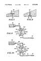
- FIG. 7is a sectional view, on an enlarged scale of one form of flap check valve for the inlet to the pump chambers;
- FIG. 8is a similar sectional view of a flap check valve for the outlet from the pump chambers
- FIG. 9is a schematic representation of a peritoneovenous shunt system including a single action pump
- FIG. 10is a similar representation of a system including a double action pump
- FIG. 11is a schematic plan view of one form of driver for the pump of the present invention.
- FIG. 12is a section on the line 12--12 of FIG. 11 and in the direction of the arrows;
- FIG. 13is a section on the line 13--13 of FIG. 11 and in the direction of the arrows;
- FIG. 14shows the several different operating positions of the driver mechanism.
- the pumpis comprised of three basic components, an elastomeric bladder 11, a solid generally rigid base member 10, and a rocker plate 13.
- the pump 10is of overall flat generally cylindrical configuration of a size adapted to be implanted under the skin of a living animal, including humans.
- Bladder 11may be formed, for example, by dipping a form of proper configuration into a suspension of natural or synthetic rubber or rubber-like latex.
- a preferred materialis medical grade silicone rubber.
- Bladder 11includes circular top and bottom walls 14 and 15, respectively, and annular side wall 16. At least one bellows pleat 17 and 18 is formed in the bladder side wall on opposite sides thereof. A tongue 19 depends from the inside top wall 14 of the bladder along a diameter of the top wall spaced equidistant from the bellows pleats 17 and 18.
- top and bottomand the like is in relation to the elements as shown in the drawings. This is independent of the positioning of those elements in the assembled pump when implanted for use in a living being.
- Base member 12is generally in the form of a flat solid cylinder having a bottom wall 20, annular side wall 21, and a pair of top faces 22 and 23 tapering downwardly from a diametric center line at the top of the base member.
- a groove 24is formed in the top surface of the base member along the center line separating the tapered faces 22 and 23.
- Bladder 11 and base member 12are of such a size and shape that when assembled tongue 19 fits into and engages groove 24 in close generally fluid-tight engagement.
- Bladder bottom wall 15 and base member bottom wall 20 and bladder annular side wall 16 and base member side wall 21are also in close generally fluid-tight engagement with one another.
- a first fluid chamber 25is formed in the space between base member tapered top face 22, bellows pleat 17 and the adjacent half of the bladder top wall.
- a second fluid chamber 26is similarly formed between the base member face 23, bellows pleat 18 and the other half of the bladder top wall.
- FIGS. 1 through 6there is an inlet port 27 to chamber 25 which is adapted to be connected through means (not shown) to a source of fluid to be transferred, such as an ascites fluid collector.
- Port 27is closed by a flexible flap member 28 functioning as a check valve to regulate one way flow through the pump chamber.
- An outlet port 29 from chamber 25connects through passage 30 to inlet port 31 to chamber 26.
- Port 31is closed by flexible flap 32 forming a further check valve.
- Discharge port 33 from chamber 26connects through a further flap valve 34 to a flow line 35 for discharge of the fluid to the bloodstream, for example.
- FIG. 7shows a typical inlet port flap check valve 36 in greater detail.
- the port at the end of passage 37is closed by a flexible flap 38, preferably recessed below the surface of the base member.
- FIG. 8shows a typical discharge port flap check valve 39 in greater detail.
- the discharge port at the end of passage 40is closed by flexible flap 41 which is preferably recessed within the base member.
- FIG. 9illustrates schematically the use of a single action pump 10A of slightly different configuration in a peritoneovenous shunt system and the manner in which flow line connections are made.
- the pump 10Ais connected through a flow line in the form of flexible tubing 42 to an ascites fluid collector 43 of the type disclosed in Buchwald et al U.S. Pat. No. 4,657,530.
- a fluid from the collector 43 and tubing 44enters the chamber through check valve 36.
- that fluidis forced through discharge port 34 and passage 45 and on the concurrent expansion stroke of chamber 26A is drawn through check valve 36 into the chamber.
- catheter 46On the compression stroke of chamber 26A that fluid is forced through the discharge port and check valve 39 into catheter 46 for transfer to a body site, such as the venous system, where the fluid may be processed by the body.
- a body sitesuch as the venous system
- the catheter 46is fitted with a check valve catheter tip 47 of the type disclosed in Dorman U.S. Pat. No. 4,657,536.
- FIG. 10illustrates schematically a similar peritoneovenous shunt system utilizing a double action pump 10B according to the present invention. Twice as much fluid is pumped by each stroke in the double action configuration.
- Pump chamber 25Bis connected through flow lines in the form of flexible tubing 48 and 49 to collector 43.
- Chamber 25Bis also connected through a flow line in the form of tubing 50 to catheter 51 for discharge of the fluid through tip 47.
- Chamber 26Bis also connected to collector 43 through flow lines in the form of tubing 52 and 49 and to the catheter 51 through tubing 53.
- FIGS. 11 through 14there is shown one form of automated power drive for the pump according to the present invention.
- the pump 10is enclosed in a cavity within housing 54.
- a rocker plate 55is provided with a pair of depending leg members 56 and 57 spaced at opposite ends of the diametric center line which overlies the diametric center line of the pump.
- the rocker plateis journaled for limited pivotal rocking movement.
- a rigid link in the form of arm 58is fixedly attached to the rocker leg member 56 for concurrent movement.
- the opposite end of arm 58is provided with a cam slot 60 in which a roller cam 61 reciprocates. Roller cam 61 is journaled for rotation relative to the end of a crank arm 62 driven through a gear box 63 of appropriate reduction by motor 64.
- Motor 64is powered by battery 65. Operation of the motor 64 by battery 65 is actuated through electronic control means 66 dependent upon the needs of the patient in whom the pump is implanted.
- the electronic controlmay be as simple as a pressure-sensitive on-off switch, or the motor may be operated in a preprogrammed timed sequence, or the like.
- Battery 65should be rechargeable by means of a power telemetry system commonly used for implanted electronic devices.
- the electronically driven pumpincludes a metal bellows 67 comprised of a stack of a plurality of concentric flat annular rings secured together alternately at their inner and outer peripheries. The topmost ring is secured to the rocker plate 55.
- the pump 10may be hermetically sealed within the bellows, flow lines to and from the pump being through connections, not shown, in the bottom plate of the bellows.
- the drive unitis a separate sealed unit that supplies only mechanical power to the pump unit. No body fluids enter the drive housing where sensitive electronic components may be located. Any diffusion of fluids through the pump components held in the driver housing cavity are returned to the body and cannot enter the drive unit.
- All of the implantable pump structure which is in contact with body fluids or tissueis composed of inert stable non-toxic biocompatible materials.
- a preferred material for components such as tubular flow linesis medical grade silicone rubber tubing. Connections may be sealed with medical grade Silastic adhesive.
- the motor driven pump housingmay be sealed and coated with silicone rubber, or polytetrafluoroethylene (Teflon), or similar material compatible with body fluids and well known for the coating of devices to be implanted within the body.
- peritoneovenous shunt systemis sized to meet particular needs.
- the componentsshould be as small as possible, consistent with the needs of the patient, to facilitate implantation.
Landscapes
- Engineering & Computer Science (AREA)
- Health & Medical Sciences (AREA)
- General Engineering & Computer Science (AREA)
- Mechanical Engineering (AREA)
- Hematology (AREA)
- Heart & Thoracic Surgery (AREA)
- Biomedical Technology (AREA)
- Life Sciences & Earth Sciences (AREA)
- Animal Behavior & Ethology (AREA)
- General Health & Medical Sciences (AREA)
- Public Health (AREA)
- Veterinary Medicine (AREA)
- Anesthesiology (AREA)
- Vascular Medicine (AREA)
- External Artificial Organs (AREA)
Abstract
Description
Claims (17)
Priority Applications (1)
| Application Number | Priority Date | Filing Date | Title |
|---|---|---|---|
| US07/121,649US5073094A (en) | 1987-11-17 | 1987-11-17 | Zero net external displacement implantable pump and driver |
Applications Claiming Priority (1)
| Application Number | Priority Date | Filing Date | Title |
|---|---|---|---|
| US07/121,649US5073094A (en) | 1987-11-17 | 1987-11-17 | Zero net external displacement implantable pump and driver |
Publications (1)
| Publication Number | Publication Date |
|---|---|
| US5073094Atrue US5073094A (en) | 1991-12-17 |
Family
ID=22397988
Family Applications (1)
| Application Number | Title | Priority Date | Filing Date |
|---|---|---|---|
| US07/121,649Expired - LifetimeUS5073094A (en) | 1987-11-17 | 1987-11-17 | Zero net external displacement implantable pump and driver |
Country Status (1)
| Country | Link |
|---|---|
| US (1) | US5073094A (en) |
Cited By (24)
| Publication number | Priority date | Publication date | Assignee | Title |
|---|---|---|---|---|
| US5643207A (en)* | 1995-04-28 | 1997-07-01 | Medtronic, Inc. | Implantable techniques for infusing a therapeutic agent with endogenous bodily fluid |
| US6589198B1 (en)* | 1998-01-29 | 2003-07-08 | David Soltanpour | Implantable micro-pump assembly |
| US6749598B1 (en)* | 1999-01-11 | 2004-06-15 | Flowmedica, Inc. | Apparatus and methods for treating congestive heart disease |
| US6994700B2 (en) | 2002-09-20 | 2006-02-07 | Flowmedica, Inc. | Apparatus and method for inserting an intra-aorta catheter through a delivery sheath |
| US7063679B2 (en) | 2002-09-20 | 2006-06-20 | Flowmedica, Inc. | Intra-aortic renal delivery catheter |
| US7122019B1 (en) | 2000-11-28 | 2006-10-17 | Flowmedica Inc. | Intra-aortic renal drug delivery catheter |
| US20070075008A1 (en)* | 2003-10-14 | 2007-04-05 | Kutushov Mikhail V | System for correcting biological fluid |
| US20070255261A1 (en)* | 2006-04-27 | 2007-11-01 | Haase James M | Infusion device with active and passive check valves |
| US7329236B2 (en) | 1999-01-11 | 2008-02-12 | Flowmedica, Inc. | Intra-aortic renal drug delivery catheter |
| US7364566B2 (en) | 2002-09-20 | 2008-04-29 | Flowmedica, Inc. | Method and apparatus for intra-aortic substance delivery to a branch vessel |
| US7481803B2 (en) | 2000-11-28 | 2009-01-27 | Flowmedica, Inc. | Intra-aortic renal drug delivery catheter |
| US7585836B2 (en) | 2004-05-14 | 2009-09-08 | Goodson Iv Harry Burt | Bi-lateral local renal delivery for treating congestive heart failure and for BNP therapy |
| US7766961B2 (en) | 2003-06-05 | 2010-08-03 | Angio Dynamics, Inc. | Systems and methods for performing bi-lateral interventions or diagnosis in branched body lumens |
| US7771401B2 (en) | 2006-06-08 | 2010-08-10 | Angiodynamics, Inc. | Selective renal cannulation and infusion systems and methods |
| US7780628B1 (en) | 1999-01-11 | 2010-08-24 | Angiodynamics, Inc. | Apparatus and methods for treating congestive heart disease |
| US7914503B2 (en) | 2002-09-20 | 2011-03-29 | Angio Dynamics | Method and apparatus for selective material delivery via an intra-renal catheter |
| US7993325B2 (en) | 2002-09-20 | 2011-08-09 | Angio Dynamics, Inc. | Renal infusion systems and methods |
| WO2012134608A3 (en)* | 2011-03-31 | 2013-01-03 | Carrier Corporation | Expander system |
| US8518011B2 (en) | 2004-03-04 | 2013-08-27 | Angiodynamics, Inc. | Sheath for use in peripheral interventions |
| WO2020257439A1 (en)* | 2019-06-19 | 2020-12-24 | Cylerus, Inc. | Compression-activated refillable pump for controlled drug delivery |
| WO2021211797A1 (en)* | 2020-04-17 | 2021-10-21 | Analog Devices, Inc. | Fluid delivery device |
| US11587839B2 (en) | 2019-06-27 | 2023-02-21 | Analog Devices, Inc. | Device with chemical reaction chamber |
| US11604084B2 (en) | 2021-04-15 | 2023-03-14 | Analog Devices, Inc. | Sensor package |
| US11796367B2 (en) | 2021-05-07 | 2023-10-24 | Analog Devices, Inc. | Fluid control system |
Citations (11)
| Publication number | Priority date | Publication date | Assignee | Title |
|---|---|---|---|---|
| US5770A (en)* | 1848-09-12 | Double-bellows pump | ||
| US14690A (en)* | 1856-04-15 | John ericsson | ||
| US20045A (en)* | 1858-04-27 | Blowing apparatus | ||
| US2334525A (en)* | 1942-07-11 | 1943-11-16 | Ernest A Zadig | Pump |
| US3330902A (en)* | 1964-07-14 | 1967-07-11 | Nakazawa Shinji | Conservator for oil-filled transformer |
| US3809087A (en)* | 1973-05-17 | 1974-05-07 | R Lewis | Closed wound suction apparatus having biased plate members |
| US4058857A (en)* | 1976-02-12 | 1977-11-22 | Runge Thomas M | Cardiac replacement pumping devices |
| US4265241A (en)* | 1979-02-28 | 1981-05-05 | Andros Incorporated | Implantable infusion device |
| US4335835A (en)* | 1978-12-26 | 1982-06-22 | Anatros Corporation | Device for the intravenous or enteric infusion of liquids into the human body at a predetermined constant rate |
| US4657536A (en)* | 1979-04-13 | 1987-04-14 | Regents Of The University Of Minnesota | Check valve catheter |
| US4657530A (en)* | 1984-04-09 | 1987-04-14 | Henry Buchwald | Compression pump-catheter |
- 1987
- 1987-11-17USUS07/121,649patent/US5073094A/ennot_activeExpired - Lifetime
Patent Citations (11)
| Publication number | Priority date | Publication date | Assignee | Title |
|---|---|---|---|---|
| US5770A (en)* | 1848-09-12 | Double-bellows pump | ||
| US14690A (en)* | 1856-04-15 | John ericsson | ||
| US20045A (en)* | 1858-04-27 | Blowing apparatus | ||
| US2334525A (en)* | 1942-07-11 | 1943-11-16 | Ernest A Zadig | Pump |
| US3330902A (en)* | 1964-07-14 | 1967-07-11 | Nakazawa Shinji | Conservator for oil-filled transformer |
| US3809087A (en)* | 1973-05-17 | 1974-05-07 | R Lewis | Closed wound suction apparatus having biased plate members |
| US4058857A (en)* | 1976-02-12 | 1977-11-22 | Runge Thomas M | Cardiac replacement pumping devices |
| US4335835A (en)* | 1978-12-26 | 1982-06-22 | Anatros Corporation | Device for the intravenous or enteric infusion of liquids into the human body at a predetermined constant rate |
| US4265241A (en)* | 1979-02-28 | 1981-05-05 | Andros Incorporated | Implantable infusion device |
| US4657536A (en)* | 1979-04-13 | 1987-04-14 | Regents Of The University Of Minnesota | Check valve catheter |
| US4657530A (en)* | 1984-04-09 | 1987-04-14 | Henry Buchwald | Compression pump-catheter |
Cited By (37)
| Publication number | Priority date | Publication date | Assignee | Title |
|---|---|---|---|---|
| US5643207A (en)* | 1995-04-28 | 1997-07-01 | Medtronic, Inc. | Implantable techniques for infusing a therapeutic agent with endogenous bodily fluid |
| US6589198B1 (en)* | 1998-01-29 | 2003-07-08 | David Soltanpour | Implantable micro-pump assembly |
| US6749598B1 (en)* | 1999-01-11 | 2004-06-15 | Flowmedica, Inc. | Apparatus and methods for treating congestive heart disease |
| US7780628B1 (en) | 1999-01-11 | 2010-08-24 | Angiodynamics, Inc. | Apparatus and methods for treating congestive heart disease |
| US7341570B2 (en) | 1999-01-11 | 2008-03-11 | Flowmedica, Inc. | Apparatus and methods for treating congestive heart disease |
| US7335192B2 (en) | 1999-01-11 | 2008-02-26 | Flowmedica, Inc. | Apparatus and methods for treating congestive heart disease |
| US7329236B2 (en) | 1999-01-11 | 2008-02-12 | Flowmedica, Inc. | Intra-aortic renal drug delivery catheter |
| US7481803B2 (en) | 2000-11-28 | 2009-01-27 | Flowmedica, Inc. | Intra-aortic renal drug delivery catheter |
| US7122019B1 (en) | 2000-11-28 | 2006-10-17 | Flowmedica Inc. | Intra-aortic renal drug delivery catheter |
| US7364566B2 (en) | 2002-09-20 | 2008-04-29 | Flowmedica, Inc. | Method and apparatus for intra-aortic substance delivery to a branch vessel |
| US8585678B2 (en) | 2002-09-20 | 2013-11-19 | Angiodynamics, Inc. | Method and apparatus for intra-aortic substance delivery to a branch vessel |
| US7104981B2 (en) | 2002-09-20 | 2006-09-12 | Flowmedica, Inc. | Apparatus and method for inserting an intra-aorta catheter through a delivery sheath |
| US7063679B2 (en) | 2002-09-20 | 2006-06-20 | Flowmedica, Inc. | Intra-aortic renal delivery catheter |
| US7241273B2 (en) | 2002-09-20 | 2007-07-10 | Flowmedica, Inc. | Intra-aortic renal delivery catheter |
| US7914503B2 (en) | 2002-09-20 | 2011-03-29 | Angio Dynamics | Method and apparatus for selective material delivery via an intra-renal catheter |
| US7563247B2 (en) | 2002-09-20 | 2009-07-21 | Angiodynamics, Inc. | Intra-aortic renal delivery catheter |
| US8012121B2 (en) | 2002-09-20 | 2011-09-06 | Angiodynamics, Inc. | Method and apparatus for selective material delivery via an intra-renal catheter |
| US7993325B2 (en) | 2002-09-20 | 2011-08-09 | Angio Dynamics, Inc. | Renal infusion systems and methods |
| US6994700B2 (en) | 2002-09-20 | 2006-02-07 | Flowmedica, Inc. | Apparatus and method for inserting an intra-aorta catheter through a delivery sheath |
| US7766961B2 (en) | 2003-06-05 | 2010-08-03 | Angio Dynamics, Inc. | Systems and methods for performing bi-lateral interventions or diagnosis in branched body lumens |
| US20070075008A1 (en)* | 2003-10-14 | 2007-04-05 | Kutushov Mikhail V | System for correcting biological fluid |
| US7601133B2 (en)* | 2003-10-14 | 2009-10-13 | Evgeny Pavlovich Germanov | System for correcting biological fluid |
| US8518011B2 (en) | 2004-03-04 | 2013-08-27 | Angiodynamics, Inc. | Sheath for use in peripheral interventions |
| US7585836B2 (en) | 2004-05-14 | 2009-09-08 | Goodson Iv Harry Burt | Bi-lateral local renal delivery for treating congestive heart failure and for BNP therapy |
| US20070255261A1 (en)* | 2006-04-27 | 2007-11-01 | Haase James M | Infusion device with active and passive check valves |
| US8323267B2 (en) | 2006-04-27 | 2012-12-04 | Medtronic, Inc. | Infusion device with active and passive check valves |
| WO2007127858A3 (en)* | 2006-04-27 | 2008-01-03 | Medtronic Inc | Infusion device with active and passive check valves |
| US7771401B2 (en) | 2006-06-08 | 2010-08-10 | Angiodynamics, Inc. | Selective renal cannulation and infusion systems and methods |
| US9316419B2 (en) | 2011-03-31 | 2016-04-19 | Carrier Corporation | Expander system |
| WO2012134608A3 (en)* | 2011-03-31 | 2013-01-03 | Carrier Corporation | Expander system |
| WO2020257439A1 (en)* | 2019-06-19 | 2020-12-24 | Cylerus, Inc. | Compression-activated refillable pump for controlled drug delivery |
| US11587839B2 (en) | 2019-06-27 | 2023-02-21 | Analog Devices, Inc. | Device with chemical reaction chamber |
| WO2021211797A1 (en)* | 2020-04-17 | 2021-10-21 | Analog Devices, Inc. | Fluid delivery device |
| US11712516B2 (en) | 2020-04-17 | 2023-08-01 | Analog Devices, Inc. | Fluid delivery device |
| EP4135792A4 (en)* | 2020-04-17 | 2024-04-17 | Analog Devices, Inc. | Fluid delivery device |
| US11604084B2 (en) | 2021-04-15 | 2023-03-14 | Analog Devices, Inc. | Sensor package |
| US11796367B2 (en) | 2021-05-07 | 2023-10-24 | Analog Devices, Inc. | Fluid control system |
Similar Documents
| Publication | Publication Date | Title |
|---|---|---|
| US5073094A (en) | Zero net external displacement implantable pump and driver | |
| US5813410A (en) | Internal body pump and systems employing same | |
| US4302854A (en) | Electrically activated ferromagnetic/diamagnetic vascular shunt for left ventricular assist | |
| US4610658A (en) | Automated peritoneovenous shunt | |
| DE69701461T2 (en) | BREAST PUMP FOR SUCTIONING BOTH BREASTS | |
| US5429584A (en) | Cardiac assist method and apparatus | |
| US4381567A (en) | Hydraulically actuated total cardiac prosthesis with reversible pump and three-way ventricular valving | |
| CA1329450C (en) | Quick-connect, totally implantable cardiac prosthesis with floating membranes and removable sensitive elements | |
| EP0288466B1 (en) | Pump | |
| US7588530B2 (en) | Devices, systems and methods for assisting blood flow | |
| US4411603A (en) | Diaphragm type blood pump for medical use | |
| US4650485A (en) | Total artificial heart | |
| US4576606A (en) | Implantable blood pump | |
| CA2004295A1 (en) | Primary fluid actuated, secondary fluid propelling system | |
| ITRM990052A1 (en) | SINGLE CHAMBER BLOOD PUMP. | |
| WO1993017730A1 (en) | Artificial heart | |
| EP0156781B1 (en) | Blood pump | |
| US4389737A (en) | Hydraulically actuated cardiac prosthesis with three-way ventricular valving | |
| JPH0288055A (en) | Integrated pennis | |
| US3771174A (en) | Artificial heart utilizing blood pulsing fluid oscillators | |
| AU641371B2 (en) | Positive displacement pump | |
| EP0661961B1 (en) | Linear motion, muscle-actuated cardiac assist device | |
| US3636570A (en) | Mechanical heart system | |
| CN115337533A (en) | An artificial whole heart operating device | |
| US5578077A (en) | Mechanical heart, body fluid and drug infusion pump |
Legal Events
| Date | Code | Title | Description |
|---|---|---|---|
| AS | Assignment | Owner name:REGENTS OF THE UNIVERSITY OF MINNESOTA, MINNEAPOLI Free format text:ASSIGNMENT OF ASSIGNORS INTEREST.;ASSIGNORS:DORMAN, FRANK D.;WIGNESS, BRUCE D.;REEL/FRAME:004813/0269 Effective date:19871109 | |
| STCF | Information on status: patent grant | Free format text:PATENTED CASE | |
| FEPP | Fee payment procedure | Free format text:PAYOR NUMBER ASSIGNED (ORIGINAL EVENT CODE: ASPN); ENTITY STATUS OF PATENT OWNER: SMALL ENTITY | |
| FPAY | Fee payment | Year of fee payment:4 | |
| CC | Certificate of correction | ||
| FPAY | Fee payment | Year of fee payment:8 | |
| AS | Assignment | Owner name:IMPLANTABLE DEVICES LIMITED PARTNERSHIP, MINNESOTA Free format text:EXCLUSIVE LICENSE AGREEMENT;ASSIGNOR:REGENTS OF THE UNIVERSITY OF MINNESOTA;REEL/FRAME:012841/0892 Effective date:20001229 | |
| FPAY | Fee payment | Year of fee payment:12 | |
| AS | Assignment | Owner name:NATIONAL INSTITUTES OF HEALTH (NIH), U.S. DEPT. OF Free format text:CONFIRMATORY LICENSE;ASSIGNOR:UNIVERSITY OF MINNESOTA TWIN CITIES;REEL/FRAME:021114/0414 Effective date:19950802 |