US5072732A - NMR instrument for testing for fluid constituents - Google Patents
NMR instrument for testing for fluid constituentsDownload PDFInfo
- Publication number
- US5072732A US5072732AUS07/427,001US42700189AUS5072732AUS 5072732 AUS5072732 AUS 5072732AUS 42700189 AUS42700189 AUS 42700189AUS 5072732 AUS5072732 AUS 5072732A
- Authority
- US
- United States
- Prior art keywords
- coil
- magnet
- glucose
- test region
- sample
- Prior art date
- Legal status (The legal status is an assumption and is not a legal conclusion. Google has not performed a legal analysis and makes no representation as to the accuracy of the status listed.)
- Expired - Lifetime
Links
- 238000012360testing methodMethods0.000titleclaimsabstractdescription54
- 239000000470constituentSubstances0.000titleclaimsabstractdescription13
- 239000012530fluidSubstances0.000titleclaimsdescription8
- 238000005481NMR spectroscopyMethods0.000claimsabstractdescription25
- 230000004044responseEffects0.000claimsdescription6
- 230000000977initiatory effectEffects0.000claimsdescription2
- WQZGKKKJIJFFOK-GASJEMHNSA-NGlucoseNatural productsOC[C@H]1OC(O)[C@H](O)[C@@H](O)[C@@H]1OWQZGKKKJIJFFOK-GASJEMHNSA-N0.000abstractdescription50
- 239000008103glucoseSubstances0.000abstractdescription50
- XLYOFNOQVPJJNP-UHFFFAOYSA-NwaterSubstancesOXLYOFNOQVPJJNP-UHFFFAOYSA-N0.000abstractdescription20
- 210000004369bloodAnatomy0.000abstractdescription19
- 239000008280bloodSubstances0.000abstractdescription19
- 238000001228spectrumMethods0.000abstractdescription19
- 210000001124body fluidAnatomy0.000abstractdescription9
- 239000010839body fluidSubstances0.000abstractdescription9
- -1for exampleSubstances0.000abstract1
- 239000000523sampleSubstances0.000description49
- NOESYZHRGYRDHS-UHFFFAOYSA-NinsulinChemical compoundN1C(=O)C(NC(=O)C(CCC(N)=O)NC(=O)C(CCC(O)=O)NC(=O)C(C(C)C)NC(=O)C(NC(=O)CN)C(C)CC)CSSCC(C(NC(CO)C(=O)NC(CC(C)C)C(=O)NC(CC=2C=CC(O)=CC=2)C(=O)NC(CCC(N)=O)C(=O)NC(CC(C)C)C(=O)NC(CCC(O)=O)C(=O)NC(CC(N)=O)C(=O)NC(CC=2C=CC(O)=CC=2)C(=O)NC(CSSCC(NC(=O)C(C(C)C)NC(=O)C(CC(C)C)NC(=O)C(CC=2C=CC(O)=CC=2)NC(=O)C(CC(C)C)NC(=O)C(C)NC(=O)C(CCC(O)=O)NC(=O)C(C(C)C)NC(=O)C(CC(C)C)NC(=O)C(CC=2NC=NC=2)NC(=O)C(CO)NC(=O)CNC2=O)C(=O)NCC(=O)NC(CCC(O)=O)C(=O)NC(CCCNC(N)=N)C(=O)NCC(=O)NC(CC=3C=CC=CC=3)C(=O)NC(CC=3C=CC=CC=3)C(=O)NC(CC=3C=CC(O)=CC=3)C(=O)NC(C(C)O)C(=O)N3C(CCC3)C(=O)NC(CCCCN)C(=O)NC(C)C(O)=O)C(=O)NC(CC(N)=O)C(O)=O)=O)NC(=O)C(C(C)CC)NC(=O)C(CO)NC(=O)C(C(C)O)NC(=O)C1CSSCC2NC(=O)C(CC(C)C)NC(=O)C(NC(=O)C(CCC(N)=O)NC(=O)C(CC(N)=O)NC(=O)C(NC(=O)C(N)CC=1C=CC=CC=1)C(C)C)CC1=CN=CN1NOESYZHRGYRDHS-UHFFFAOYSA-N0.000description20
- LFQSCWFLJHTTHZ-UHFFFAOYSA-NEthanolChemical compoundCCOLFQSCWFLJHTTHZ-UHFFFAOYSA-N0.000description18
- 102000004877InsulinHuman genes0.000description10
- 108090001061InsulinProteins0.000description10
- 229940125396insulinDrugs0.000description10
- 210000002966serumAnatomy0.000description9
- 238000004458analytical methodMethods0.000description8
- 238000000034methodMethods0.000description8
- 239000000463materialSubstances0.000description7
- 206010012601diabetes mellitusDiseases0.000description6
- 238000010586diagramMethods0.000description6
- 210000003462veinAnatomy0.000description6
- 239000000126substanceSubstances0.000description5
- 210000001367arteryAnatomy0.000description4
- 210000004204blood vesselAnatomy0.000description4
- 238000003745diagnosisMethods0.000description3
- 229940079593drugDrugs0.000description3
- 239000003814drugSubstances0.000description3
- 230000000737periodic effectEffects0.000description3
- 238000005070samplingMethods0.000description3
- 210000001519tissueAnatomy0.000description3
- 241001465754MetazoaSpecies0.000description2
- 239000000654additiveSubstances0.000description2
- 230000000996additive effectEffects0.000description2
- WQZGKKKJIJFFOK-VFUOTHLCSA-Nbeta-D-glucoseChemical compoundOC[C@H]1O[C@@H](O)[C@H](O)[C@@H](O)[C@@H]1OWQZGKKKJIJFFOK-VFUOTHLCSA-N0.000description2
- 210000000988bone and boneAnatomy0.000description2
- 210000004905finger nailAnatomy0.000description2
- 238000002513implantationMethods0.000description2
- 230000006698inductionEffects0.000description2
- 239000007924injectionSubstances0.000description2
- 238000002347injectionMethods0.000description2
- 210000000282nailAnatomy0.000description2
- 238000012545processingMethods0.000description2
- 230000009466transformationEffects0.000description2
- 235000013522vodkaNutrition0.000description2
- QTBSBXVTEAMEQO-UHFFFAOYSA-MAcetateChemical groupCC([O-])=OQTBSBXVTEAMEQO-UHFFFAOYSA-M0.000description1
- 108010015776Glucose oxidaseProteins0.000description1
- 239000004366Glucose oxidaseSubstances0.000description1
- JVTAAEKCZFNVCJ-UHFFFAOYSA-MLactateChemical compoundCC(O)C([O-])=OJVTAAEKCZFNVCJ-UHFFFAOYSA-M0.000description1
- 230000004913activationEffects0.000description1
- 230000002411adverseEffects0.000description1
- 230000008901benefitEffects0.000description1
- 230000008859changeEffects0.000description1
- 230000006835compressionEffects0.000description1
- 238000007906compressionMethods0.000description1
- 238000002059diagnostic imagingMethods0.000description1
- 238000012631diagnostic techniqueMethods0.000description1
- 201000010099diseaseDiseases0.000description1
- 208000037265diseases, disorders, signs and symptomsDiseases0.000description1
- 230000001747exhibiting effectEffects0.000description1
- 230000006870functionEffects0.000description1
- 229940116332glucose oxidaseDrugs0.000description1
- 235000019420glucose oxidaseNutrition0.000description1
- 125000002791glucosyl groupChemical groupC1([C@H](O)[C@@H](O)[C@H](O)[C@H](O1)CO)*0.000description1
- 230000005802health problemEffects0.000description1
- 238000003384imaging methodMethods0.000description1
- 239000007943implantSubstances0.000description1
- 238000009434installationMethods0.000description1
- 230000002452interceptive effectEffects0.000description1
- 230000005415magnetizationEffects0.000description1
- 125000002496methyl groupChemical group[H]C([H])([H])*0.000description1
- 125000000325methylidene groupChemical group[H]C([H])=*0.000description1
- 238000012986modificationMethods0.000description1
- 230000004048modificationEffects0.000description1
- 238000012544monitoring processMethods0.000description1
- 239000002324mouth washSubstances0.000description1
- 238000000655nuclear magnetic resonance spectrumMethods0.000description1
- 230000003647oxidationEffects0.000description1
- 238000007254oxidation reactionMethods0.000description1
- 230000035515penetrationEffects0.000description1
- 230000001766physiological effectEffects0.000description1
- 230000036470plasma concentrationEffects0.000description1
- 230000008569processEffects0.000description1
- 230000008439repair processEffects0.000description1
- 238000011160researchMethods0.000description1
Images


Classifications
- A—HUMAN NECESSITIES
- A61—MEDICAL OR VETERINARY SCIENCE; HYGIENE
- A61B—DIAGNOSIS; SURGERY; IDENTIFICATION
- A61B5/00—Measuring for diagnostic purposes; Identification of persons
- A61B5/68—Arrangements of detecting, measuring or recording means, e.g. sensors, in relation to patient
- A61B5/6846—Arrangements of detecting, measuring or recording means, e.g. sensors, in relation to patient specially adapted to be brought in contact with an internal body part, i.e. invasive
- A61B5/6867—Arrangements of detecting, measuring or recording means, e.g. sensors, in relation to patient specially adapted to be brought in contact with an internal body part, i.e. invasive specially adapted to be attached or implanted in a specific body part
- A61B5/6876—Blood vessel
- A—HUMAN NECESSITIES
- A61—MEDICAL OR VETERINARY SCIENCE; HYGIENE
- A61B—DIAGNOSIS; SURGERY; IDENTIFICATION
- A61B5/00—Measuring for diagnostic purposes; Identification of persons
- A61B5/05—Detecting, measuring or recording for diagnosis by means of electric currents or magnetic fields; Measuring using microwaves or radio waves
- A61B5/055—Detecting, measuring or recording for diagnosis by means of electric currents or magnetic fields; Measuring using microwaves or radio waves involving electronic [EMR] or nuclear [NMR] magnetic resonance, e.g. magnetic resonance imaging
- A—HUMAN NECESSITIES
- A61—MEDICAL OR VETERINARY SCIENCE; HYGIENE
- A61B—DIAGNOSIS; SURGERY; IDENTIFICATION
- A61B5/00—Measuring for diagnostic purposes; Identification of persons
- A61B5/145—Measuring characteristics of blood in vivo, e.g. gas concentration or pH-value ; Measuring characteristics of body fluids or tissues, e.g. interstitial fluid or cerebral tissue
- A61B5/14532—Measuring characteristics of blood in vivo, e.g. gas concentration or pH-value ; Measuring characteristics of body fluids or tissues, e.g. interstitial fluid or cerebral tissue for measuring glucose, e.g. by tissue impedance measurement
- A—HUMAN NECESSITIES
- A61—MEDICAL OR VETERINARY SCIENCE; HYGIENE
- A61B—DIAGNOSIS; SURGERY; IDENTIFICATION
- A61B5/00—Measuring for diagnostic purposes; Identification of persons
- A61B5/68—Arrangements of detecting, measuring or recording means, e.g. sensors, in relation to patient
- A61B5/6801—Arrangements of detecting, measuring or recording means, e.g. sensors, in relation to patient specially adapted to be attached to or worn on the body surface
- A61B5/6813—Specially adapted to be attached to a specific body part
- A61B5/6825—Hand
- A61B5/6826—Finger
- A—HUMAN NECESSITIES
- A61—MEDICAL OR VETERINARY SCIENCE; HYGIENE
- A61B—DIAGNOSIS; SURGERY; IDENTIFICATION
- A61B5/00—Measuring for diagnostic purposes; Identification of persons
- A61B5/68—Arrangements of detecting, measuring or recording means, e.g. sensors, in relation to patient
- A61B5/6801—Arrangements of detecting, measuring or recording means, e.g. sensors, in relation to patient specially adapted to be attached to or worn on the body surface
- A61B5/683—Means for maintaining contact with the body
- A61B5/6838—Clamps or clips
- A—HUMAN NECESSITIES
- A61—MEDICAL OR VETERINARY SCIENCE; HYGIENE
- A61B—DIAGNOSIS; SURGERY; IDENTIFICATION
- A61B5/00—Measuring for diagnostic purposes; Identification of persons
- A61B5/68—Arrangements of detecting, measuring or recording means, e.g. sensors, in relation to patient
- A61B5/6846—Arrangements of detecting, measuring or recording means, e.g. sensors, in relation to patient specially adapted to be brought in contact with an internal body part, i.e. invasive
- A61B5/6879—Means for maintaining contact with the body
- A61B5/6884—Clamps or clips
- G—PHYSICS
- G01—MEASURING; TESTING
- G01R—MEASURING ELECTRIC VARIABLES; MEASURING MAGNETIC VARIABLES
- G01R33/00—Arrangements or instruments for measuring magnetic variables
- G01R33/20—Arrangements or instruments for measuring magnetic variables involving magnetic resonance
- G01R33/44—Arrangements or instruments for measuring magnetic variables involving magnetic resonance using nuclear magnetic resonance [NMR]
- G01R33/46—NMR spectroscopy
- G01R33/465—NMR spectroscopy applied to biological material, e.g. in vitro testing
Definitions
- This inventionprimarily relates to a method and to an instrument for use in medical diagnosis, and in particular, to detecting and determining glucose concentration in blood.
- Diabetesis a health problem affecting many individuals and its prevalence is increasing.
- the usual treatment for diabetesis single or multiple insulin injections daily.
- Insulinis available in slowly or rapidly absorbed forms, which may be injected alone or in combination. Such insulin injections have been effective in treating the disease and in prolonging life.
- testingis periodic, and thus the administration of insulin is periodic which can result in wide variations in glucose concentration over time and peaks in the glucose concentration. Such variations can have physiological effects which may be adverse to the patient.
- the litmus-type systemhas the disadvantage in that it is invasive and the patient is periodically and repeatedly pricked for blood samples.
- breathalyzer testsmay be inaccurate in that non-ingested alcohol, such as in mouthwashes, will provide false results.
- Nuclear magnetic resonanceis a diagnostic technique which is used widely for medical imaging and medical diagnosis.
- the test objectis subjected to a first or biasing magnetic field to align previously randomly oriented 1 H protons in the nuclei and a second field or burst of energy to increase the energy of a selected nucleus.
- the second magnetic field or energy sourceis turned of, the return to the first alignment releases energy which is detected and analyzed.
- This releaseis analyzed or processed to form an image or spectrum. From the spectrum, the presence of particular molecular bonds can be observed and associated with various molecules or materials from which the concentration of that molecule or material can be determined.
- NMR machinesare most frequently used for imaging sections of a human body and require large magnets, for example, superconducting magnets. The machines are therefore quite large and expensive. Furthermore, the NMR testing of fluids has required invasive sample withdrawal techniques, which sample was then tested in the larger machines.
- This inventionprovides a method and a portable NMR instrument for use in noninvasively analyzing body fluids for the concentration of various constituents.
- a diabeticcan use the instrument to noninvasively and substantially instantaneously analyze his blood for glucose, thereby eliminating the need to invasively obtain a blood sample which is then tested.
- a patientcan periodically, frequent-y if necessary, a nd painlessly analyze his blood for glucose concentration.
- This devicemay also be useful in analyzing body fluids for alcohol or drugs.
- the deviceis portable and provided with means for receiving an extremity of the patient, such as a finger, and exposing the extremity to a first or biasing magnetic field and a second field or energy source.
- Sensorsare provided for sensing the rates of relaxation or energy release so as to develop the spectrum.
- Analytical meansare coupled to the sensors for receiving and analyzing the signals emitted discriminating between various peaks, comparing the amplitude or height of various peaks, such as water and glucose, and normalizing the analysis by reference to a standard sample so as to obtain the concentration of constituents in the tested materials.
- the first or biasing magnetfor providing the first magnetic field.
- the biasing magnetis physically much smaller than the magnets used in standard NMR machines.
- the magnetmay be one pound in weight and may exhibit a field strength of at least five to six kilogauss.
- Another componentis a coil apparatus for applying a second field or energy to the test sample and sensing the energy released therefrom. A single coil or multiple coils can be used.
- Yet another important element of this inventionis the electronic circuit used for the analysis. This circuit is controlled by a microprocessor that is programmed to control the application of the second field or energy source and cooperates in detecting and analyzing the spectra received from the sample when the field is relaxed. Operation of the microprocessor is disclosed herein.
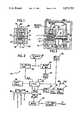
- FIG. 1is a vertical cross-sectional view of an instrument according to this invention
- FIG. 2is a vertical cross-sectional view taken along line 2--2 of FIG. 1 and also showing a housing and other components;
- FIG. 3is a block-type schematic diagram for the circuitry to operate the instrument
- FIGS. 4a to 4care flow charts showing the operation of the instrument
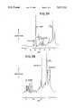
- FIGS. 5a and 5bare representative NMR spectrums showing the water, glucose peaks and alcohol used for analysis
- FIG. 6is a schematic diagram showing a threecoil system for use in the instrument
- FIG. 7is a schematic diagram showing the electrical connections for the three-coil system of FIG. 6;
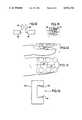
- FIG. 8shows an NMR probe for implantation in a body
- FIG. 9is a schematic block-type diagram of the electrical circuit for use with the implantable probe of FIG. 8;
- FIG. 10shows a human arm having a distended vein for NMR testing
- FIG. 11is a fragmentary and sectional view of a magnetic probe for use in NMR analysis using a surface blood vessel
- FIG. 12is a schematic representation of an alternative circuit arrangement for use with separate energizing and receiving coils
- FIG. 13is a schematic representation of the coil and magnet relationships which may be used in an arrangement of the type shown in FIG. 12;
- FIG. 14is a schematic representation of a multicoil arrangement
- FIG. 15is a top view of the elements of FIG. 14.
- FIG. 16is a side view of an alternative C-shaped magnet which may replace the magnetic structure of FIGS. 1 and 2.
- FIGS. 1-3a first embodiment of the test instrument is shown. Other embodiments and features will be discussed after consideration of principal features of this invention by way of the first embodiment.
- the test instrument 10is shown as including a boxshaped assembly which defines a finger-receiving recess 12 therein.
- the assemblyincludes a body section 14 defined by the top, bottom and elongated side walls 16, 18, 20 and 22 and the back wall 24.
- the assemblyis enclosed in a two piece cover or housing 25A and 25B within which the electronic components discussed hereinafter are also enclosed. Alternatively, the electronics can be enclosed in a separate housing connected to the body section.
- a pair of first or biasing permanent magnets 26 and 28form the top and bottom walls 18 and 22, are positioned opposite one another and provide the first aligning magnetic field.
- poles of the respective magnetsare aligned so that the field is additive and provide constructive interference, and the pole pieces or shoes shape the magnetic field in the finger-receiving recess 12.
- This alignmentis shown by the "X" designation which indicates that the magnetic field from the magnets passes through the recess 12 in the same direction, in FIG. 2, into the paper.
- a sample holder or container 34 for a standard sample starting apparatus 30is shown positioned in the recess.
- the apparatusincludes a compression biasing spring 32 pressing at one end against the back wall 24 and against the rear wall 30 of sample holder 34 at the other end.
- the holder 34is mounted on a post-like member 35, which is guided through an aperture 37.
- a start switch 36is mounted to the back wall offset from the member 35 so that when the sample holder 34 is pushed against the spring toward the back wall, the holder will depress the start switch to start operation of the instrument. Release of the sample holder will release the switch.
- the switchmay also be mounted outside, say beneath the head 39, and operated upon movement of the head 39.
- a surface coil 38is mounted in the housing adjacent one of the permanent magnets 26 and 28.
- the coilproduces the second field and acts as a source of energy for realignment and for sensing purposes.
- the second field produced by the surface coilis transverse to the first or permanent magnet field.
- the surface coilhas been selected for this embodiment because the depth of magnetization (i.e., extent of penetration of the field) is related to the diameter of the coil and can thus be controlled.
- the surface coil 38may be a single coil for both energization and sensing.
- the coilcan also be an assembly in which there are multiple coils, each of which are for energization and sensing.
- the coilmay be an assembly of at least two coils, where at least one is for energization and at least one other coil is for sensing. These alternatives are shown in FIGS. 13, 14 and 15.
- the cover or housing 25A and 25B for the electronicsis provided with an electronic interlock system (schematically shown as 56 in FIG. 3) so that unauthorized opening or removal of the cover will disable the electronics described hereinafter, thereby preventing unauthorized tampering or repair of the device which could destroy calibration and result in improper usage.
- an electronic interlock system(schematically shown as 56 in FIG. 3) so that unauthorized opening or removal of the cover will disable the electronics described hereinafter, thereby preventing unauthorized tampering or repair of the device which could destroy calibration and result in improper usage.
- testis run by the patient inserting his finger into the instrument and pushing the sample holder toward the back wall 24 and into engagement with the start switch 36 to start the analysis as described hereinafter.
- the fingeris positioned so that the fingernail is located adjacent the surface coil. This positioning is chosen as the fingernail is dead tissue but has a bed of active blood vessels positioned just below the nail. These vessels are believed to provide an accurate testing site. In many other test sites, live body tissue or bone must be penetrated in order to test blood in a vessel, which means that the tissue or bone will emit signals due to testing which act as noise and may interfere with analysis of the blood for glucose concentration.
- the finger regionis preferable, since the nail is essentially dead material and produces little, if any, interfering noise, thereby increasing the signal to noise ratio. It is believed that other body extremities can be tested, for example, the ear of either a human or other animals.
- the testing circuit 40includes a battery power supply 42.
- a commercial AC power supply and battery chargermay be used to supply energy to the battery.
- Depression of the start switchactivates the circuit and, thereby the microprocessor 44.
- the microprocessoractivates an RF generator and cyclically-operated gate 46, which excites the surface coil 38 (or coil assembly) for applying the second field, raising the energy state and realigning the nuclei.
- the RF generatoris deactivated, thereby permitting the nuclei (dipoles) to relax or return to the first alignment.
- the surface coildetects the energy released during relaxation and realignment. Those signals are received by receiver/gate 48, converted from analog signals to digital signals by the A/D converter 50 and fed to the microprocessor 44.
- a read only memory (ROM) 52is provided for storing the program for use with the microprocessor in calibrating the machine and analyzing and displaying test results. If separate coils are used, then the circuit is changed so that the RF generator is connected to the energizing coil and the receiver is connected to the sensing coil as shown in FIG. 12.
- the ROMis continuously energized by the battery 54.
- a cover interlock switch 56is provided between the ROM 52 and battery 54 to deenergize the ROM in the event the electronics cover 25A or 25B is opened, removed or tampered with. In such an event, the switch 56 is opened and the program in the ROM is erased.
- the ROMmay be selected from the well-known classes of electrically erasable or alterable ROM's.
- the specific function of the ROM-cover interlock arrangementmay be selected as desired, i.e., to generate an error message on the panel display, or simply to disable the apparatus from operating or exhibiting any panel display.
- Various other forms of electronic-type interlocksare well-known in the computer art.
- the testing circuit 40also includes a display 58, preferably digital, which is connected to the microprocessor and a group of status lamps (read 60, calibrate 62, display 64 and error 66). which indicate the status of the system's operation.
- a display 58preferably digital, which is connected to the microprocessor and a group of status lamps (read 60, calibrate 62, display 64 and error 66). which indicate the status of the system's operation.
- the ROM 52includes a program as represented by the flow chart of FIGS. 4a -4c, whereby operation of the tester is controlled.
- the operation of the testeris as follows:
- a fingeris inserted to depress the sample holder and activate the start switch.
- the fingeris tested.
- the standard sample test resultsare compared with predetermined calibration data previously entered in memory to determine if the standard sample data reading is still within preset and allowable tolerances.
- the finger test resultsare compared with the sample standard test result data and the finger data is normalized and proportioned to determine glucose concentration.
- FIGS. 4a through 4cthe various phases of the microprocessor and ROM are shown. These phases can considered as follows:
- the flow chartbegins with depression of the starting switch 36, initiation of the program and activation of the read light 60.
- a one second homodecoupling pulse(or a plurality of pulses) to saturate the water peak is activated.
- a five microsecond sample pulseis taken, and the free induction decay output from the A/D converter is noted.
- the data pointsare stored in the memory 45 and the process is repeated (i.e., looped) perhaps one hundred times.
- the right-hand columnthere is shown a series of diagrams representing, the one second homodecoupling pulse, the five microsecond sampling pulse, the decay, and a Fourier transformation of the decay data points.
- the amplitude (Amp.) of the responseis recorded along the Y-axis. After the samplings, the read lamp is deactivated, the accumulated responses are multiplied by an exponential decay to provide line broadening, a Fourier transformation is run, and a spectrum is stored as the chemical shifts versus the peak height as patient data.
- the standard sample reading cycleis next activated.
- the calibrate lightis turned on, and the start switch is released.
- one second homodecoupling pulse(or plurality of pulses) is provided, a five microsecond sampling pulse is taken, the free induction decay is recorded, and the data points are stored in the memory 45.
- the systemis then repeated again, perhaps one hundred times.
- the accumulated responsesare multiplied by an exponential decay to improve line broadening, Fourier transforms are run and the spectrum of chemical shifts versus peak height is stored as sample data.
- the standard sampleinitially contains predetermined amounts of the constituent material or materials being tested for and acts as a reference level.
- the next stepis an operational check where the spectrum of chemical shifts versus peak height data for the standard sample is recalled and compared to the standard data previously taken within allowable tolerances. If the error is not within an acceptable tolerance, the error display lamp 66 is lit and the operator notified. If the data is within an allowable error, the system proceeds to the next step. It is noted that on the right-hand side of FIG. 4c that a comparison is shown between the standard sample data and standard sample spectrum showing the allowable shifts, peak height and frequency with amplitude plotted along the Y-axis.
- the next stepis to normalize the patient data and standard sample data for equal water heights.
- the patient datais recalled and the standard sample data is recalled.
- the patient data water peak heightis scaled to match the standard sample data water peak height.
- the systemthen executes the next step which is to calculate the glucose level.
- a ratiois obtained of the patient data glucose peak height and the standard sample data peak height. This ratio is then multiplied by the known standard sample glucose to water ratio to obtain the patient reading and multiplied by a concentration factor (K) from the standard sample and expressed in milligrams per deciliter or some other convenient unit. Then the patient glucose level is displayed in relation to plasma level. Normal glucose concentration is ninety milligrams per deciliter.
- the standard sampleis prepared having a known glucose concentration expressed, for example, in milligram of glucose/deciliter of water (mg/dl) and is referred to as K.
- the patient's water peak heightis normalized by determining the ratio of water standard peak height/water patient peak height. This ratio can be referred to as gain.
- the patient's glucose peak heightis normalize d by multiplying the patient glucose peak height by the gain. The result is the normalized patient glucose ##EQU1##
- FIG. 5aa 1 H typical blood spectrum is shown with the water (H 2 O) and glucose peaks clearly shown. It is the ratio of the peak heights as determined from the calibration and test samples that permit determination of the test sample glucose concentration.
- FIG. 5ashows the work of Jay Block, "Analysis of Serum by High Yield NMR", Clin. Chem. 28/9, 1983, (1982) taken from normal blood serum. Sample volume is 0.4 ml serum to which has been added 0.1 ml of 2 H 2 O for field lock. In addition, 10 mmol/1 of TSP was added to the 2 H 2 O to serve as a reference to assign chemical shifts and peak area. The work was done on a WM 500 Burker spectrometer.
- FIG. 5bis an enlarged portion of the 1 H blood spectrum of FIG. 5a showing the ethanol and water peaks, as also reported by Bock and showing the spectrum of serum obtained 30 minutes after ingestin 30 ml of vodka and water peaks, as also reported by Bock and is included to show a spectrum of serum obtained 30 minutes after ingesting 30 ml of vodka.
- the ethanol concentration measured by routine gaschromatographic methodwas only 30 mg/1, while the methyl resonance of ethanol at 1.20 ppm was detected with better than 40:1 signal to noise ratio.
- the methylene resonanceis buried in the glucose region.
- a large peakappears at 1.93 ppm, the position of acetate, presumably derived from the oxidation of ingested ethanol.
- the ethanol resonancehad a much greater intensity and dominated the spectra.
- FIG. 6Another embodiment 70 of this invention is shown in FIG. 6.
- three coil pairs 72, 74 and 76are provided which lie in the same plane and are equally spaced, that is at equally spaced 60° intervals.
- the coilsare arranged to provide constructive interference at the center of the coils where a sample (such as a finger or test tube) is to be located.
- These coil pairsact as the energization or realignment coil and as the sensor, in a manner similar to the surface coil described hereinbefore. This arrangement is believed to provide better signal discrimination by increasing the signal-to-noise ratio.
- the coilsare mounted in a housing similar to that shown in FIGS. 1 and 2 and are controlled by a circuit and in the manner similar to that described in connection with FIG. 3. Physically, the standard and sample is inserted into one of the coils, such as the test tube 78 into coil 72. The portion to be tested is located at the center of the coils as shown.
- test sampleis then tested as described above with coils first acting as the energization or realignment magnets and then as sensors or receivers.
- coilsfirst acting as the energization or realignment magnets and then as sensors or receivers.
- this systemoperates in the same manner as above.
- FIGS. 8 and 9In those cases in which it may be desirable to implant a portion of the instrument, reference is made to FIGS. 8 and 9.
- a third embodiment 80is shown in FIG. 8, which is constructed to surround a blood vessel which is internal of or within a body, for example, a vein or artery in the body.
- the test deviceincludes the principal magnet 82, which in this case is C-shaped and a pair of RF coils 84.
- the vein or artery 86is positioned between the coil pairs and the poles of the magnet. By so doing, blood in the vein or artery is subjected to the first magnetic field, and the energization or realignment field and relaxation is sensed by coils 84.
- test instrument 90is constructed for surgical implantation as shown in FIG. 9.
- Such a devicehas two component parts: one part is the internal or implanted portion 92 and the other part is the external or power supply and sensing part 94.
- the two partsare electronically coupled by transformer-like members as described h®r®in.
- an external AC power supply 96is inductively coupled to an internal power supply 98.
- the internal power supply 98powers the NMR unit 100, which is connected to probe and magnet unit 102. Signals from the probe and magnet are received by the receiver 104, which is inductively coupled to the microprocessor 106, through the coil element 108. The microprocessor then provides an output to the digital display 110 of the glucose concentration.
- the magnet and probe assembly 102is in the same form as that in FIG. 8 and is positioned to surround an artery.
- the signal processingis performed by the microprocessor in the same manner as with the other embodiments, particularly FIG. 3.
- a surface blood vesselis distended and used to analyze for glucose concentration.
- a surface blood vesselis distended and used to analyze for glucose concentration.
- FIGS. 10 and 11Such an embodiment is shown in FIGS. 10 and 11, where a patient's arm 120 is shown surrounded by a pressurizable cuff 122 for causing a vein 124 to protrude or distend from the skin surface.
- the NMR unitis fitted on either side of the protruding vessel at the surface of the arm.
- a C-shaped permanent magnet 126is arranged so that its north and south poles (N & S) are on opposite sides of the vessel.
- a surface coil 128, like that in FIGS. 1-2,is employed for energization and realignment and sensing. Testing circuitry of the type shown in FIG. 3 is also employed in the embodiment of FIGS. 10 and II.
- a principal advantage of the test instrument shown hereinis that the device is smaller than the large NMR test instruments now used at hospitals, etc.
- the present instrumentsinclude a large principal magnet for surrounding the body of a patient.
- the principal magnetmay be smaller so that the instrument may be mounted on a table top, carried in a brief case, or be even smaller.
- the magnetIn order to achieve such a device, the magnet must be small in size, be of a comparatively light weight, such as one pound, and still exhibit an adequate field strength. Adequate strengths should be on the order of at least five to six kilogauss.
- One particularly suitable material containing Neodyniumis manufactured by General Motors Corporation.
- FIG. 12shows the generator and gate 46 and the receiver 46 and gate 48, respectively, connected to separate transmit and receive coils 38', 38".
- FIG. 13shows an embodiment of the coils 38' and 38" along with the field directions, including the bias field Ho, at 90° with respect to one another.
- FIGS. 14 and 15illustrate the use of a plurality of surface coils 38", which are connected for additive fields, as a single transmit/receive arrangement.
- FIG. 16shows an alternate bias magnet, similar to that shown in FIG. 11
- the magnet 138comprises a pair of spaced pole pieces 132, 134, which define a gap for receiving, in this example, a finger.
Landscapes
- Health & Medical Sciences (AREA)
- Life Sciences & Earth Sciences (AREA)
- Physics & Mathematics (AREA)
- Molecular Biology (AREA)
- General Health & Medical Sciences (AREA)
- Animal Behavior & Ethology (AREA)
- Veterinary Medicine (AREA)
- Biomedical Technology (AREA)
- Heart & Thoracic Surgery (AREA)
- Medical Informatics (AREA)
- Pathology (AREA)
- Surgery (AREA)
- Biophysics (AREA)
- Engineering & Computer Science (AREA)
- Public Health (AREA)
- High Energy & Nuclear Physics (AREA)
- Nuclear Medicine, Radiotherapy & Molecular Imaging (AREA)
- Spectroscopy & Molecular Physics (AREA)
- Condensed Matter Physics & Semiconductors (AREA)
- General Physics & Mathematics (AREA)
- Vascular Medicine (AREA)
- Radiology & Medical Imaging (AREA)
- Emergency Medicine (AREA)
- Optics & Photonics (AREA)
- Measurement Of The Respiration, Hearing Ability, Form, And Blood Characteristics Of Living Organisms (AREA)
- Investigating Or Analysing Biological Materials (AREA)
Abstract
Description
Claims (1)
Priority Applications (1)
| Application Number | Priority Date | Filing Date | Title |
|---|---|---|---|
| US07/427,001US5072732A (en) | 1986-09-04 | 1989-10-23 | NMR instrument for testing for fluid constituents |
Applications Claiming Priority (2)
| Application Number | Priority Date | Filing Date | Title |
|---|---|---|---|
| US06/904,000US4875486A (en) | 1986-09-04 | 1986-09-04 | Instrument and method for non-invasive in vivo testing for body fluid constituents |
| US07/427,001US5072732A (en) | 1986-09-04 | 1989-10-23 | NMR instrument for testing for fluid constituents |
Related Parent Applications (1)
| Application Number | Title | Priority Date | Filing Date |
|---|---|---|---|
| US06/904,000ContinuationUS4875486A (en) | 1986-09-04 | 1986-09-04 | Instrument and method for non-invasive in vivo testing for body fluid constituents |
Publications (1)
| Publication Number | Publication Date |
|---|---|
| US5072732Atrue US5072732A (en) | 1991-12-17 |
Family
ID=27027253
Family Applications (1)
| Application Number | Title | Priority Date | Filing Date |
|---|---|---|---|
| US07/427,001Expired - LifetimeUS5072732A (en) | 1986-09-04 | 1989-10-23 | NMR instrument for testing for fluid constituents |
Country Status (1)
| Country | Link |
|---|---|
| US (1) | US5072732A (en) |
Cited By (55)
| Publication number | Priority date | Publication date | Assignee | Title |
|---|---|---|---|---|
| US5183045A (en)* | 1988-06-17 | 1993-02-02 | Otsuka Electronic Co., Ltd. | Nmr measuring method and measuring apparatus for tissue of a living body |
| US5296811A (en)* | 1991-11-22 | 1994-03-22 | Instrumentarium Corp. | Magnetic resonance imaging apparatus and method |
| US5317265A (en)* | 1992-09-16 | 1994-05-31 | Weinstock Ronald J | Computerized magnetic resonance analyzer |
| US5322682A (en)* | 1992-08-06 | 1994-06-21 | The Regents Of The University Of California | Method for quantitatively measuring and mapping stored iron in tissue using MRI |
| US5375597A (en)* | 1993-10-13 | 1994-12-27 | Howell; Jerome C. | Digital magnetic resonance shock-monitoring method |
| US5398681A (en)* | 1992-12-10 | 1995-03-21 | Sunshine Medical Instruments, Inc. | Pocket-type instrument for non-invasive measurement of blood glucose concentration |
| US5448992A (en)* | 1992-12-10 | 1995-09-12 | Sunshine Medical Instruments, Inc. | Method and apparatus for non-invasive phase sensitive measurement of blood glucose concentration |
| US5592086A (en)* | 1992-09-16 | 1997-01-07 | Weinstock; Ronald J. | Automated computerized magnetic resonance detector and analyzer |
| US5666956A (en)* | 1996-05-20 | 1997-09-16 | Buchert; Janusz Michal | Instrument and method for non-invasive monitoring of human tissue analyte by measuring the body's infrared radiation |
| US5685300A (en)* | 1994-04-01 | 1997-11-11 | Kuenstner; J. Todd | Noninvasive and in-vitro measurement of glucose and cholesterol by nuclear magnetic resonance spectroscopy |
| US5833610A (en)* | 1995-08-31 | 1998-11-10 | Research Development Corporation Of Japan | Magnetic resonance imaging of cerebral blood flow and diagnosis of diabetes |
| US5978694A (en)* | 1997-02-27 | 1999-11-02 | Uri Rapoport | Method and apparatus for detecting a magnetically responsive substance |
| WO2000045697A1 (en)* | 1997-02-27 | 2000-08-10 | Uri Rapoport | Method and apparatus for detecting a magnetically responsive substance |
| US6285448B1 (en) | 1997-05-05 | 2001-09-04 | J. Todd Kuenstner | Clinical analyte determination by infrared spectroscopy |
| EP1132047A1 (en)* | 2000-03-06 | 2001-09-12 | Medos SA | Mini-invasive nuclear magnetic resonance spectroscopy catheter probe |
| EP1132048A1 (en)* | 2000-03-06 | 2001-09-12 | Medos SA | Implantable nuclear magnetic resonance spectrometer |
| US6317618B1 (en)* | 1999-06-02 | 2001-11-13 | Odin Technologies Ltd. | Transportable intraoperative magnetic resonance imaging apparatus |
| GB2366867A (en)* | 2000-09-14 | 2002-03-20 | Rolls Royce Plc | NMR detection of contaminants or additives in oil |
| US6393310B1 (en) | 1998-09-09 | 2002-05-21 | J. Todd Kuenstner | Methods and systems for clinical analyte determination by visible and infrared spectroscopy |
| US6690166B2 (en)* | 2001-09-26 | 2004-02-10 | Southwest Research Institute | Nuclear magnetic resonance technology for non-invasive characterization of bone porosity and pore size distributions |
| US20040058386A1 (en)* | 2001-01-15 | 2004-03-25 | Wishart David Scott | Automatic identificaiton of compounds in a sample mixture by means of nmr spectroscopy |
| US20040167801A1 (en)* | 1998-04-30 | 2004-08-26 | James Say | Analyte monitoring device and methods of use |
| US20040193031A1 (en)* | 1999-12-28 | 2004-09-30 | Pindi Products, Inc. | Method and apparatus for non-invasive analysis of blood glucose |
| US20040227494A1 (en)* | 2003-05-15 | 2004-11-18 | Cal Swanson | Constant voltage discharge device |
| US20050024053A1 (en)* | 2003-07-29 | 2005-02-03 | Care Ian C.D. | Fluid monitoring arrangement |
| US20050203363A1 (en)* | 2002-09-24 | 2005-09-15 | Pendragon Medical Ltd. | Device for the measurement of glucose concentrations |
| KR100757891B1 (en) | 2005-11-29 | 2007-09-11 | 한국전자통신연구원 | Non-invasive contact type bio signal measuring apparatus and method |
| US20080088308A1 (en)* | 2005-01-14 | 2008-04-17 | Carpenter Scott E | Methods of In Vitro Analysis Using Time-Domain Nmr Spectroscopy |
| US20080319293A1 (en)* | 2007-06-21 | 2008-12-25 | Pindi Products, Inc. | Sample scanning and analysis system and methods for using the same |
| US20090198175A1 (en)* | 1998-04-30 | 2009-08-06 | Abbott Diabetes Care Inc. | Analyte Monitoring Device and Methods of Use |
| US20090312615A1 (en)* | 2005-11-10 | 2009-12-17 | Andreas Caduff | Device for Determining the Glucose Level in Body Tissue |
| US20100065751A1 (en)* | 2007-06-21 | 2010-03-18 | Pindi Products, Inc. | Non-invasive scanning apparatuses |
| US20100069731A1 (en)* | 2007-06-21 | 2010-03-18 | Pindi Products, Inc. | Non-Invasive Weight and Performance Management |
| US20100072386A1 (en)* | 2007-06-21 | 2010-03-25 | Pindi Products, Inc. | Non-Invasive Determination of Characteristics of a Sample |
| US20100072994A1 (en)* | 2006-11-08 | 2010-03-25 | T2 Biosystems , Inc. | Nmr systems for in vivo detection of analytes |
| US20120197107A1 (en)* | 2011-01-31 | 2012-08-02 | Case Western Reserve University | Glucose analyzing blood examiner (gabe) |
| US8259299B2 (en) | 2007-06-21 | 2012-09-04 | Rf Science & Technology Inc. | Gas scanning and analysis |
| US8287454B2 (en) | 1998-04-30 | 2012-10-16 | Abbott Diabetes Care Inc. | Analyte monitoring device and methods of use |
| US8346337B2 (en) | 1998-04-30 | 2013-01-01 | Abbott Diabetes Care Inc. | Analyte monitoring device and methods of use |
| US8465425B2 (en) | 1998-04-30 | 2013-06-18 | Abbott Diabetes Care Inc. | Analyte monitoring device and methods of use |
| US8652043B2 (en) | 2001-01-02 | 2014-02-18 | Abbott Diabetes Care Inc. | Analyte monitoring device and methods of use |
| US8688188B2 (en) | 1998-04-30 | 2014-04-01 | Abbott Diabetes Care Inc. | Analyte monitoring device and methods of use |
| US20140194715A1 (en)* | 2011-01-31 | 2014-07-10 | Case Western Reserve University | Glucose Analyzing Blood Examiner |
| DE102012224334A1 (en)* | 2012-12-21 | 2014-07-17 | Bernd Diehl | Method for determining the blood alcohol concentration by means of quantitative NMR spectroscopy |
| US20150018638A1 (en)* | 2012-02-08 | 2015-01-15 | Anatech Advanced Nmr Alorithms Technologies Ltd. | Apparatus and method for non-invasive measurement of blood parameters |
| US8974386B2 (en) | 1998-04-30 | 2015-03-10 | Abbott Diabetes Care Inc. | Analyte monitoring device and methods of use |
| US9066695B2 (en) | 1998-04-30 | 2015-06-30 | Abbott Diabetes Care Inc. | Analyte monitoring device and methods of use |
| CN105433954A (en)* | 2015-12-18 | 2016-03-30 | 深圳市柳迪科技有限公司 | Non-invasive blood glucose detection equipment |
| CN105486646A (en)* | 2014-10-07 | 2016-04-13 | 精工爱普生株式会社 | Signal detection method, calibration curve creation method, quantification method |
| US9772388B2 (en) | 2011-09-28 | 2017-09-26 | Koninklijke Philips N.V. | Method and system for quantifying hepatic fat in humans |
| US20190271749A1 (en)* | 2018-03-05 | 2019-09-05 | Texas Tech University System | Method and system for non-invasive measurement of metabolic health |
| WO2020127028A1 (en)* | 2018-12-20 | 2020-06-25 | Robert Bosch Gmbh | Nmr measuring apparatus having a sensor device for intracorporeal arrangement |
| US20200367795A1 (en)* | 2018-01-18 | 2020-11-26 | New York University | System and method for blood glucose monitoring using magnetic resonance spectroscopy |
| US11237237B2 (en) | 2018-09-14 | 2022-02-01 | 10250929 Canada Inc. | Method and system for in-vivo, and non-invasive measurement of metabolite levels |
| US12245849B2 (en) | 2023-08-08 | 2025-03-11 | Synex Medical Inc. | System and method for nuclear magnetic resonance measurement of blood analyte levels |
Citations (1)
| Publication number | Priority date | Publication date | Assignee | Title |
|---|---|---|---|---|
| US4875486A (en)* | 1986-09-04 | 1989-10-24 | Advanced Techtronics, Inc. | Instrument and method for non-invasive in vivo testing for body fluid constituents |
- 1989
- 1989-10-23USUS07/427,001patent/US5072732A/ennot_activeExpired - Lifetime
Patent Citations (1)
| Publication number | Priority date | Publication date | Assignee | Title |
|---|---|---|---|---|
| US4875486A (en)* | 1986-09-04 | 1989-10-24 | Advanced Techtronics, Inc. | Instrument and method for non-invasive in vivo testing for body fluid constituents |
Cited By (155)
| Publication number | Priority date | Publication date | Assignee | Title |
|---|---|---|---|---|
| US5183045A (en)* | 1988-06-17 | 1993-02-02 | Otsuka Electronic Co., Ltd. | Nmr measuring method and measuring apparatus for tissue of a living body |
| US5296811A (en)* | 1991-11-22 | 1994-03-22 | Instrumentarium Corp. | Magnetic resonance imaging apparatus and method |
| US5322682A (en)* | 1992-08-06 | 1994-06-21 | The Regents Of The University Of California | Method for quantitatively measuring and mapping stored iron in tissue using MRI |
| US5317265A (en)* | 1992-09-16 | 1994-05-31 | Weinstock Ronald J | Computerized magnetic resonance analyzer |
| US5517119A (en)* | 1992-09-16 | 1996-05-14 | Weinstock; Ronald J. | Automated computerized magnetic resonance detector and analyzer |
| US5592086A (en)* | 1992-09-16 | 1997-01-07 | Weinstock; Ronald J. | Automated computerized magnetic resonance detector and analyzer |
| US5671301A (en)* | 1992-12-10 | 1997-09-23 | Sunshine Medical Instruments, Inc. | Optical phase modulator for high resolution phase measurements |
| US5398681A (en)* | 1992-12-10 | 1995-03-21 | Sunshine Medical Instruments, Inc. | Pocket-type instrument for non-invasive measurement of blood glucose concentration |
| US5448992A (en)* | 1992-12-10 | 1995-09-12 | Sunshine Medical Instruments, Inc. | Method and apparatus for non-invasive phase sensitive measurement of blood glucose concentration |
| US5375597A (en)* | 1993-10-13 | 1994-12-27 | Howell; Jerome C. | Digital magnetic resonance shock-monitoring method |
| US5685300A (en)* | 1994-04-01 | 1997-11-11 | Kuenstner; J. Todd | Noninvasive and in-vitro measurement of glucose and cholesterol by nuclear magnetic resonance spectroscopy |
| US5833610A (en)* | 1995-08-31 | 1998-11-10 | Research Development Corporation Of Japan | Magnetic resonance imaging of cerebral blood flow and diagnosis of diabetes |
| US5666956A (en)* | 1996-05-20 | 1997-09-16 | Buchert; Janusz Michal | Instrument and method for non-invasive monitoring of human tissue analyte by measuring the body's infrared radiation |
| US5978694A (en)* | 1997-02-27 | 1999-11-02 | Uri Rapoport | Method and apparatus for detecting a magnetically responsive substance |
| WO2000045697A1 (en)* | 1997-02-27 | 2000-08-10 | Uri Rapoport | Method and apparatus for detecting a magnetically responsive substance |
| US6285448B1 (en) | 1997-05-05 | 2001-09-04 | J. Todd Kuenstner | Clinical analyte determination by infrared spectroscopy |
| US8840553B2 (en) | 1998-04-30 | 2014-09-23 | Abbott Diabetes Care Inc. | Analyte monitoring device and methods of use |
| US8372005B2 (en) | 1998-04-30 | 2013-02-12 | Abbott Diabetes Care Inc. | Analyte monitoring device and methods of use |
| US8734346B2 (en) | 1998-04-30 | 2014-05-27 | Abbott Diabetes Care Inc. | Analyte monitoring device and methods of use |
| US8688188B2 (en) | 1998-04-30 | 2014-04-01 | Abbott Diabetes Care Inc. | Analyte monitoring device and methods of use |
| US8672844B2 (en) | 1998-04-30 | 2014-03-18 | Abbott Diabetes Care Inc. | Analyte monitoring device and methods of use |
| US8670815B2 (en) | 1998-04-30 | 2014-03-11 | Abbott Diabetes Care Inc. | Analyte monitoring device and methods of use |
| US8666469B2 (en) | 1998-04-30 | 2014-03-04 | Abbott Diabetes Care Inc. | Analyte monitoring device and methods of use |
| US8660627B2 (en) | 1998-04-30 | 2014-02-25 | Abbott Diabetes Care Inc. | Analyte monitoring device and methods of use |
| US8738109B2 (en) | 1998-04-30 | 2014-05-27 | Abbott Diabetes Care Inc. | Analyte monitoring device and methods of use |
| US8744545B2 (en) | 1998-04-30 | 2014-06-03 | Abbott Diabetes Care Inc. | Analyte monitoring device and methods of use |
| US8649841B2 (en) | 1998-04-30 | 2014-02-11 | Abbott Diabetes Care Inc. | Analyte monitoring device and methods of use |
| US20040167801A1 (en)* | 1998-04-30 | 2004-08-26 | James Say | Analyte monitoring device and methods of use |
| US8641619B2 (en) | 1998-04-30 | 2014-02-04 | Abbott Diabetes Care Inc. | Analyte monitoring device and methods of use |
| US8622906B2 (en) | 1998-04-30 | 2014-01-07 | Abbott Diabetes Care Inc. | Analyte monitoring device and methods of use |
| US8617071B2 (en) | 1998-04-30 | 2013-12-31 | Abbott Diabetes Care Inc. | Analyte monitoring device and methods of use |
| US8612159B2 (en) | 1998-04-30 | 2013-12-17 | Abbott Diabetes Care Inc. | Analyte monitoring device and methods of use |
| US8597189B2 (en) | 1998-04-30 | 2013-12-03 | Abbott Diabetes Care Inc. | Analyte monitoring device and methods of use |
| US8480580B2 (en) | 1998-04-30 | 2013-07-09 | Abbott Diabetes Care Inc. | Analyte monitoring device and methods of use |
| US8473021B2 (en) | 1998-04-30 | 2013-06-25 | Abbott Diabetes Care Inc. | Analyte monitoring device and methods of use |
| US8465425B2 (en) | 1998-04-30 | 2013-06-18 | Abbott Diabetes Care Inc. | Analyte monitoring device and methods of use |
| US10478108B2 (en) | 1998-04-30 | 2019-11-19 | Abbott Diabetes Care Inc. | Analyte monitoring device and methods of use |
| US8409131B2 (en) | 1998-04-30 | 2013-04-02 | Abbott Diabetes Care Inc. | Analyte monitoring device and methods of use |
| US8391945B2 (en) | 1998-04-30 | 2013-03-05 | Abbott Diabetes Care Inc. | Analyte monitoring device and methods of use |
| US8774887B2 (en) | 1998-04-30 | 2014-07-08 | Abbott Diabetes Care Inc. | Analyte monitoring device and methods of use |
| US8380273B2 (en) | 1998-04-30 | 2013-02-19 | Abbott Diabetes Care Inc. | Analyte monitoring device and methods of use |
| US8366614B2 (en) | 1998-04-30 | 2013-02-05 | Abbott Diabetes Care Inc. | Analyte monitoring device and methods of use |
| US8734348B2 (en) | 1998-04-30 | 2014-05-27 | Abbott Diabetes Care Inc. | Analyte monitoring device and methods of use |
| US20090198175A1 (en)* | 1998-04-30 | 2009-08-06 | Abbott Diabetes Care Inc. | Analyte Monitoring Device and Methods of Use |
| US9326714B2 (en) | 1998-04-30 | 2016-05-03 | Abbott Diabetes Care Inc. | Analyte monitoring device and methods of use |
| US9072477B2 (en) | 1998-04-30 | 2015-07-07 | Abbott Diabetes Care Inc. | Analyte monitoring device and methods of use |
| US9066694B2 (en) | 1998-04-30 | 2015-06-30 | Abbott Diabetes Care Inc. | Analyte monitoring device and methods of use |
| US9066697B2 (en) | 1998-04-30 | 2015-06-30 | Abbott Diabetes Care Inc. | Analyte monitoring device and methods of use |
| US9066695B2 (en) | 1998-04-30 | 2015-06-30 | Abbott Diabetes Care Inc. | Analyte monitoring device and methods of use |
| US9042953B2 (en) | 1998-04-30 | 2015-05-26 | Abbott Diabetes Care Inc. | Analyte monitoring device and methods of use |
| US20100099969A1 (en)* | 1998-04-30 | 2010-04-22 | Abbott Diabetes Care Inc. | Analyte Monitoring Device and Methods of Use |
| US20100099968A1 (en)* | 1998-04-30 | 2010-04-22 | Abbott Diabetes Care Inc. | Analyte Monitoring Device and Methods of Use |
| US20100100078A1 (en)* | 1998-04-30 | 2010-04-22 | Abbott Diabetes Care Inc. | Analyte Monitoring Device and Methods of Use |
| US20100268048A1 (en)* | 1998-04-30 | 2010-10-21 | Abbott Diabetes Care Inc. | Analyte Monitoring Device and Methods of Use |
| US9014773B2 (en) | 1998-04-30 | 2015-04-21 | Abbott Diabetes Care Inc. | Analyte monitoring device and methods of use |
| US8357091B2 (en) | 1998-04-30 | 2013-01-22 | Abbott Diabetes Care Inc. | Analyte monitoring device and methods of use |
| US9011331B2 (en) | 1998-04-30 | 2015-04-21 | Abbott Diabetes Care Inc. | Analyte monitoring device and methods of use |
| US8162829B2 (en) | 1998-04-30 | 2012-04-24 | Abbott Diabetes Care Inc. | Analyte monitoring device and methods of use |
| US8175673B2 (en) | 1998-04-30 | 2012-05-08 | Abbott Diabetes Care Inc. | Analyte monitoring device and methods of use |
| US8224413B2 (en) | 1998-04-30 | 2012-07-17 | Abbott Diabetes Care Inc. | Analyte monitoring device and methods of use |
| US8226557B2 (en) | 1998-04-30 | 2012-07-24 | Abbott Diabetes Care Inc. | Analyte monitoring device and methods of use |
| US8226555B2 (en) | 1998-04-30 | 2012-07-24 | Abbott Diabetes Care Inc. | Analyte monitoring device and methods of use |
| US8226558B2 (en) | 1998-04-30 | 2012-07-24 | Abbott Diabetes Care Inc. | Analyte monitoring device and methods of use |
| US8231532B2 (en) | 1998-04-30 | 2012-07-31 | Abbott Diabetes Care Inc. | Analyte monitoring device and methods of use |
| US8974386B2 (en) | 1998-04-30 | 2015-03-10 | Abbott Diabetes Care Inc. | Analyte monitoring device and methods of use |
| US8235896B2 (en) | 1998-04-30 | 2012-08-07 | Abbott Diabetes Care Inc. | Analyte monitoring device and methods of use |
| US8255031B2 (en)* | 1998-04-30 | 2012-08-28 | Abbott Diabetes Care Inc. | Analyte monitoring device and methods of use |
| US8880137B2 (en) | 1998-04-30 | 2014-11-04 | Abbott Diabetes Care Inc. | Analyte monitoring device and methods of use |
| US8260392B2 (en) | 1998-04-30 | 2012-09-04 | Abbott Diabetes Care Inc. | Analyte monitoring device and methods of use |
| US8265726B2 (en) | 1998-04-30 | 2012-09-11 | Abbott Diabetes Care Inc. | Analyte monitoring device and methods of use |
| US8273022B2 (en) | 1998-04-30 | 2012-09-25 | Abbott Diabetes Care Inc. | Analyte monitoring device and methods of use |
| US8275439B2 (en) | 1998-04-30 | 2012-09-25 | Abbott Diabetes Care Inc. | Analyte monitoring device and methods of use |
| US8287454B2 (en) | 1998-04-30 | 2012-10-16 | Abbott Diabetes Care Inc. | Analyte monitoring device and methods of use |
| US8306598B2 (en) | 1998-04-30 | 2012-11-06 | Abbott Diabetes Care Inc. | Analyte monitoring device and methods of use |
| US8346337B2 (en) | 1998-04-30 | 2013-01-01 | Abbott Diabetes Care Inc. | Analyte monitoring device and methods of use |
| US8346336B2 (en) | 1998-04-30 | 2013-01-01 | Abbott Diabetes Care Inc. | Analyte monitoring device and methods of use |
| US8353829B2 (en) | 1998-04-30 | 2013-01-15 | Abbott Diabetes Care Inc. | Analyte monitoring device and methods of use |
| US6393310B1 (en) | 1998-09-09 | 2002-05-21 | J. Todd Kuenstner | Methods and systems for clinical analyte determination by visible and infrared spectroscopy |
| US6317618B1 (en)* | 1999-06-02 | 2001-11-13 | Odin Technologies Ltd. | Transportable intraoperative magnetic resonance imaging apparatus |
| US7316649B2 (en)* | 1999-12-28 | 2008-01-08 | Pindi Products, Inc. | Method and apparatus for non-invasive analysis of blood glucose |
| US20040193031A1 (en)* | 1999-12-28 | 2004-09-30 | Pindi Products, Inc. | Method and apparatus for non-invasive analysis of blood glucose |
| US6658281B2 (en)* | 2000-03-06 | 2003-12-02 | Medos S.A. | Mini-invasive nuclear magnetic resonance spectroscopy catheter probe |
| EP1132048A1 (en)* | 2000-03-06 | 2001-09-12 | Medos SA | Implantable nuclear magnetic resonance spectrometer |
| EP1132047A1 (en)* | 2000-03-06 | 2001-09-12 | Medos SA | Mini-invasive nuclear magnetic resonance spectroscopy catheter probe |
| JP2001269326A (en)* | 2000-03-06 | 2001-10-02 | Medos Sa | Graftable nuclear magnetic resonance spectrometer |
| US6600945B2 (en)* | 2000-03-06 | 2003-07-29 | Medos S.A. | Implantable nuclear magnetic resonance spectrometer |
| US6794865B2 (en) | 2000-09-14 | 2004-09-21 | Rolls-Royce Plc | Monitoring the health of a fluid system |
| US20020036501A1 (en)* | 2000-09-14 | 2002-03-28 | Rolls-Royce Plc | Monitoring the health of a fluid system |
| GB2366867A (en)* | 2000-09-14 | 2002-03-20 | Rolls Royce Plc | NMR detection of contaminants or additives in oil |
| US9011332B2 (en) | 2001-01-02 | 2015-04-21 | Abbott Diabetes Care Inc. | Analyte monitoring device and methods of use |
| US8652043B2 (en) | 2001-01-02 | 2014-02-18 | Abbott Diabetes Care Inc. | Analyte monitoring device and methods of use |
| US9498159B2 (en) | 2001-01-02 | 2016-11-22 | Abbott Diabetes Care Inc. | Analyte monitoring device and methods of use |
| US9610034B2 (en) | 2001-01-02 | 2017-04-04 | Abbott Diabetes Care Inc. | Analyte monitoring device and methods of use |
| US8668645B2 (en) | 2001-01-02 | 2014-03-11 | Abbott Diabetes Care Inc. | Analyte monitoring device and methods of use |
| US20050075796A1 (en)* | 2001-01-11 | 2005-04-07 | Chenomx, Inc. | Automatic identification of compounds in a sample mixture by means of NMR spectroscopy |
| US20040058386A1 (en)* | 2001-01-15 | 2004-03-25 | Wishart David Scott | Automatic identificaiton of compounds in a sample mixture by means of nmr spectroscopy |
| US7191069B2 (en) | 2001-01-15 | 2007-03-13 | Chenomx, Inc. | Automatic identification of compounds in a sample mixture by means of NMR spectroscopy |
| US7181348B2 (en) | 2001-01-15 | 2007-02-20 | Chenomx, Inc. | Automatic identification of compounds in a sample mixture by means of NMR spectroscopy |
| US6690166B2 (en)* | 2001-09-26 | 2004-02-10 | Southwest Research Institute | Nuclear magnetic resonance technology for non-invasive characterization of bone porosity and pore size distributions |
| US20050203363A1 (en)* | 2002-09-24 | 2005-09-15 | Pendragon Medical Ltd. | Device for the measurement of glucose concentrations |
| US7534208B2 (en)* | 2002-09-24 | 2009-05-19 | Max Link | Device for the measurement of glucose concentrations |
| US20040227494A1 (en)* | 2003-05-15 | 2004-11-18 | Cal Swanson | Constant voltage discharge device |
| US20050024053A1 (en)* | 2003-07-29 | 2005-02-03 | Care Ian C.D. | Fluid monitoring arrangement |
| US7486071B2 (en)* | 2003-07-29 | 2009-02-03 | Rolls-Royce Plc | Fluid monitoring arrangement |
| US20080088308A1 (en)* | 2005-01-14 | 2008-04-17 | Carpenter Scott E | Methods of In Vitro Analysis Using Time-Domain Nmr Spectroscopy |
| US8134365B2 (en) | 2005-01-14 | 2012-03-13 | Bayer Healthcare Llc | Methods of in-vitro analysis using time-domain NMR spectroscopy |
| US7550971B2 (en) | 2005-01-14 | 2009-06-23 | Bayer Healthcare Llc | Methods of in vitro analysis using time-domain NMR spectroscopy |
| US20090219022A1 (en)* | 2005-01-14 | 2009-09-03 | Bayer Healthcare Llc | Methods of In-Vitro Analysis Using Time-Domain NMR Spectroscopy |
| US7940045B2 (en) | 2005-01-14 | 2011-05-10 | Bayer Healthcare Llc | Methods of in-vitro analysis using time-domain NMR spectroscopy |
| US20110175614A1 (en)* | 2005-01-14 | 2011-07-21 | Bayer Healthcare Llc | Methods of in-vitro analysis using time-domain nmr spectroscopy |
| US9326716B2 (en) | 2005-11-01 | 2016-05-03 | Abbott Diabetes Care Inc. | Analyte monitoring device and methods of use |
| US11103165B2 (en) | 2005-11-01 | 2021-08-31 | Abbott Diabetes Care Inc. | Analyte monitoring device and methods of use |
| US11911151B1 (en) | 2005-11-01 | 2024-02-27 | Abbott Diabetes Care Inc. | Analyte monitoring device and methods of use |
| US8915850B2 (en) | 2005-11-01 | 2014-12-23 | Abbott Diabetes Care Inc. | Analyte monitoring device and methods of use |
| US8920319B2 (en) | 2005-11-01 | 2014-12-30 | Abbott Diabetes Care Inc. | Analyte monitoring device and methods of use |
| US11399748B2 (en) | 2005-11-01 | 2022-08-02 | Abbott Diabetes Care Inc. | Analyte monitoring device and methods of use |
| US11363975B2 (en) | 2005-11-01 | 2022-06-21 | Abbott Diabetes Care Inc. | Analyte monitoring device and methods of use |
| US9078607B2 (en) | 2005-11-01 | 2015-07-14 | Abbott Diabetes Care Inc. | Analyte monitoring device and methods of use |
| US11272867B2 (en) | 2005-11-01 | 2022-03-15 | Abbott Diabetes Care Inc. | Analyte monitoring device and methods of use |
| US10201301B2 (en) | 2005-11-01 | 2019-02-12 | Abbott Diabetes Care Inc. | Analyte monitoring device and methods of use |
| US10231654B2 (en) | 2005-11-01 | 2019-03-19 | Abbott Diabetes Care Inc. | Analyte monitoring device and methods of use |
| US10952652B2 (en) | 2005-11-01 | 2021-03-23 | Abbott Diabetes Care Inc. | Analyte monitoring device and methods of use |
| US20090312615A1 (en)* | 2005-11-10 | 2009-12-17 | Andreas Caduff | Device for Determining the Glucose Level in Body Tissue |
| US9713447B2 (en) | 2005-11-10 | 2017-07-25 | Biovotion Ag | Device for determining the glucose level in body tissue |
| KR100757891B1 (en) | 2005-11-29 | 2007-09-11 | 한국전자통신연구원 | Non-invasive contact type bio signal measuring apparatus and method |
| US20100072994A1 (en)* | 2006-11-08 | 2010-03-25 | T2 Biosystems , Inc. | Nmr systems for in vivo detection of analytes |
| US8368402B2 (en)* | 2006-11-08 | 2013-02-05 | T2 Biosystems, Inc. | NMR systems for in vivo detection of analytes |
| US8836334B2 (en) | 2006-11-08 | 2014-09-16 | T2 Biosystems, Inc. | NMR systems for in vivo detection of analytes |
| US20100069731A1 (en)* | 2007-06-21 | 2010-03-18 | Pindi Products, Inc. | Non-Invasive Weight and Performance Management |
| US20080319293A1 (en)* | 2007-06-21 | 2008-12-25 | Pindi Products, Inc. | Sample scanning and analysis system and methods for using the same |
| US8647272B2 (en) | 2007-06-21 | 2014-02-11 | Rf Science & Technology Inc | Non-invasive scanning apparatuses |
| US8647273B2 (en) | 2007-06-21 | 2014-02-11 | RF Science & Technology, Inc. | Non-invasive weight and performance management |
| US20100072386A1 (en)* | 2007-06-21 | 2010-03-25 | Pindi Products, Inc. | Non-Invasive Determination of Characteristics of a Sample |
| US8259299B2 (en) | 2007-06-21 | 2012-09-04 | Rf Science & Technology Inc. | Gas scanning and analysis |
| US20100065751A1 (en)* | 2007-06-21 | 2010-03-18 | Pindi Products, Inc. | Non-invasive scanning apparatuses |
| US8382668B2 (en) | 2007-06-21 | 2013-02-26 | Rf Science & Technology Inc. | Non-invasive determination of characteristics of a sample |
| US10264993B2 (en) | 2007-06-21 | 2019-04-23 | Rf Science & Technology Inc. | Sample scanning and analysis system and methods for using the same |
| US20120197107A1 (en)* | 2011-01-31 | 2012-08-02 | Case Western Reserve University | Glucose analyzing blood examiner (gabe) |
| US20140194715A1 (en)* | 2011-01-31 | 2014-07-10 | Case Western Reserve University | Glucose Analyzing Blood Examiner |
| US9772388B2 (en) | 2011-09-28 | 2017-09-26 | Koninklijke Philips N.V. | Method and system for quantifying hepatic fat in humans |
| US10159413B2 (en)* | 2012-02-08 | 2018-12-25 | Anatech Advanced Nmr Algorithms Technologies Ltd. | Apparatus and method for non-invasive measurement of blood parameters |
| US20150018638A1 (en)* | 2012-02-08 | 2015-01-15 | Anatech Advanced Nmr Alorithms Technologies Ltd. | Apparatus and method for non-invasive measurement of blood parameters |
| DE102012224334B4 (en)* | 2012-12-21 | 2015-11-19 | Bernd Diehl | Method for determining the blood alcohol concentration by means of quantitative NMR spectroscopy |
| DE102012224334A1 (en)* | 2012-12-21 | 2014-07-17 | Bernd Diehl | Method for determining the blood alcohol concentration by means of quantitative NMR spectroscopy |
| CN105486646A (en)* | 2014-10-07 | 2016-04-13 | 精工爱普生株式会社 | Signal detection method, calibration curve creation method, quantification method |
| CN105433954B (en)* | 2015-12-18 | 2018-03-16 | 深圳市柳迪科技有限公司 | A kind of noninvasive dynamics monitoring equipment |
| CN105433954A (en)* | 2015-12-18 | 2016-03-30 | 深圳市柳迪科技有限公司 | Non-invasive blood glucose detection equipment |
| US20200367795A1 (en)* | 2018-01-18 | 2020-11-26 | New York University | System and method for blood glucose monitoring using magnetic resonance spectroscopy |
| US10775458B2 (en)* | 2018-03-05 | 2020-09-15 | Texas Tech University System | Method and system for non-invasive measurement of metabolic health |
| US20190271749A1 (en)* | 2018-03-05 | 2019-09-05 | Texas Tech University System | Method and system for non-invasive measurement of metabolic health |
| US11237237B2 (en) | 2018-09-14 | 2022-02-01 | 10250929 Canada Inc. | Method and system for in-vivo, and non-invasive measurement of metabolite levels |
| US11561271B2 (en)* | 2018-09-14 | 2023-01-24 | 10250929 Canada Inc. | Method and system for in-vivo, and non-invasive measurement of metabolite levels |
| US11579225B2 (en) | 2018-09-14 | 2023-02-14 | 10250929 Canada Inc. | Method and system for in-vivo, and non-invasive measurement of metabolite levels |
| WO2020127028A1 (en)* | 2018-12-20 | 2020-06-25 | Robert Bosch Gmbh | Nmr measuring apparatus having a sensor device for intracorporeal arrangement |
| US12245849B2 (en) | 2023-08-08 | 2025-03-11 | Synex Medical Inc. | System and method for nuclear magnetic resonance measurement of blood analyte levels |
Similar Documents
| Publication | Publication Date | Title |
|---|---|---|
| US5072732A (en) | NMR instrument for testing for fluid constituents | |
| US4875486A (en) | Instrument and method for non-invasive in vivo testing for body fluid constituents | |
| US4994746A (en) | Method of and apparatus for nuclear magnetic resonance analysis using true logarithmic amplifier | |
| US8836334B2 (en) | NMR systems for in vivo detection of analytes | |
| US6723048B2 (en) | Method and apparatus for non-invasive analysis of blood glucose | |
| US10159413B2 (en) | Apparatus and method for non-invasive measurement of blood parameters | |
| US6898455B2 (en) | Method for providing optimal drug dosage | |
| EP0621491B1 (en) | Methods for the in vivo measurement of the concentration of NMR-detectable xenobiotic compounds | |
| EP0068762A2 (en) | Method and apparatus for determining and imaging fats in biological samples | |
| CA2339325C (en) | Implantable nuclear magnetic resonance spectrometer | |
| CA1288475C (en) | Instrument and method for testing for fluid constituents | |
| JPH0721471B2 (en) | Nuclear magnetic resonance apparatus for testing constituents of body fluids | |
| CA2339316C (en) | Mini-invasive nuclear magnetic resonance spectroscopy catheter probe | |
| Günther et al. | In vivo 19F nuclear magnetic resonance of a monofluorinated neuroleptic in the rat | |
| US6979999B2 (en) | Method and system of mapping oxygen concentration across a region-of-interest | |
| US20030201773A1 (en) | Measuring device, nuclear magnetic reasonance tomograph, measuring method and imaging method | |
| GB2253702A (en) | apparatus and method | |
| Zuo et al. | Proton MRS Measurement of p-boronophenylalanine (BPA): a Potential MRS application for Boron Neutron Capture Therapy (BNCT) | |
| Ichihashi et al. | p-BORONOPHENYLALANINE AND BORIC ACID USING 11B-NMR | |
| Berliner et al. | Introduction to in Vivo EPR | |
| Fossel | 5192264 Methods and apparatus for treating disease states using oxidized lipoproteins |
Legal Events
| Date | Code | Title | Description |
|---|---|---|---|
| STCF | Information on status: patent grant | Free format text:PATENTED CASE | |
| FPAY | Fee payment | Year of fee payment:4 | |
| AS | Assignment | Owner name:ELBIT-ATI, LTD., ISRAEL Free format text:ASSIGNMENT OF ASSIGNORS INTEREST;ASSIGNOR:ADVANCED TECHTRONICS, INC.;REEL/FRAME:009197/0687 Effective date:19961126 | |
| AS | Assignment | Owner name:ELBIT-ATI (1992), LTD., ISRAEL Free format text:ATTORNEY'S DECLARATION;ASSIGNOR:ELBIT-ATI, LTD.;REEL/FRAME:009479/0945 Effective date:19980906 Owner name:FOXBORO NMR, LTD., ISRAEL Free format text:CHANGE OF NAME;ASSIGNOR:ELBIT-ATI (1992), LTD.;REEL/FRAME:009479/0963 Effective date:19971029 | |
| FEPP | Fee payment procedure | Free format text:PAT HLDR NO LONGER CLAIMS SMALL ENT STAT AS SMALL BUSINESS (ORIGINAL EVENT CODE: LSM2); ENTITY STATUS OF PATENT OWNER: LARGE ENTITY | |
| FPAY | Fee payment | Year of fee payment:8 | |
| FPAY | Fee payment | Year of fee payment:12 | |
| AS | Assignment | Owner name:QUALION LTD., ISRAEL Free format text:CHANGE OF NAME;ASSIGNOR:FOXBORO NMR LTD.;REEL/FRAME:019140/0936 Effective date:20051227 |