US5072235A - Method and apparatus for the electronic detection of air inside a thermal inkjet printhead - Google Patents
Method and apparatus for the electronic detection of air inside a thermal inkjet printheadDownload PDFInfo
- Publication number
- US5072235A US5072235AUS07/543,497US54349790AUS5072235AUS 5072235 AUS5072235 AUS 5072235AUS 54349790 AUS54349790 AUS 54349790AUS 5072235 AUS5072235 AUS 5072235A
- Authority
- US
- United States
- Prior art keywords
- heating element
- cell
- average value
- printing operation
- current
- Prior art date
- Legal status (The legal status is an assumption and is not a legal conclusion. Google has not performed a legal analysis and makes no representation as to the accuracy of the status listed.)
- Expired - Lifetime
Links
- 238000001514detection methodMethods0.000titleclaimsabstractdescription19
- 238000000034methodMethods0.000titleclaimsdescription16
- 238000007639printingMethods0.000claimsabstractdescription33
- 238000010438heat treatmentMethods0.000claimsdescription48
- 230000008859changeEffects0.000claimsdescription6
- 238000012935AveragingMethods0.000claimsdescription2
- 239000003990capacitorSubstances0.000abstractdescription3
- 230000000903blocking effectEffects0.000abstractdescription2
- 239000000976inkSubstances0.000description32
- 238000003491arrayMethods0.000description6
- 241001379910Ephemera danicaSpecies0.000description4
- XUIMIQQOPSSXEZ-UHFFFAOYSA-NSiliconChemical compound[Si]XUIMIQQOPSSXEZ-UHFFFAOYSA-N0.000description4
- 238000012360testing methodMethods0.000description4
- 238000010586diagramMethods0.000description3
- 230000006870functionEffects0.000description3
- 229910052710siliconInorganic materials0.000description3
- 239000010703siliconSubstances0.000description3
- 230000009471actionEffects0.000description2
- 230000003213activating effectEffects0.000description2
- 230000007547defectEffects0.000description2
- 239000007789gasSubstances0.000description2
- 238000007641inkjet printingMethods0.000description2
- 230000005499meniscusEffects0.000description2
- 238000012986modificationMethods0.000description2
- 230000004048modificationEffects0.000description2
- 230000009467reductionEffects0.000description2
- 230000004913activationEffects0.000description1
- 230000002411adverseEffects0.000description1
- 238000004891communicationMethods0.000description1
- 238000012217deletionMethods0.000description1
- 230000037430deletionEffects0.000description1
- 238000013461designMethods0.000description1
- 238000003795desorptionMethods0.000description1
- 230000003292diminished effectEffects0.000description1
- 238000010291electrical methodMethods0.000description1
- 238000001914filtrationMethods0.000description1
- 230000037406food intakeEffects0.000description1
- 239000007788liquidSubstances0.000description1
- 230000014759maintenance of locationEffects0.000description1
- 239000000463materialSubstances0.000description1
- 230000007246mechanismEffects0.000description1
- 238000012544monitoring processMethods0.000description1
- 230000010355oscillationEffects0.000description1
- 230000008569processEffects0.000description1
- 230000000717retained effectEffects0.000description1
- 230000000630rising effectEffects0.000description1
- 239000004065semiconductorSubstances0.000description1
- 239000000758substrateSubstances0.000description1
- 238000011144upstream manufacturingMethods0.000description1
Images


Classifications
- B—PERFORMING OPERATIONS; TRANSPORTING
- B41—PRINTING; LINING MACHINES; TYPEWRITERS; STAMPS
- B41J—TYPEWRITERS; SELECTIVE PRINTING MECHANISMS, i.e. MECHANISMS PRINTING OTHERWISE THAN FROM A FORME; CORRECTION OF TYPOGRAPHICAL ERRORS
- B41J2/00—Typewriters or selective printing mechanisms characterised by the printing or marking process for which they are designed
- B41J2/005—Typewriters or selective printing mechanisms characterised by the printing or marking process for which they are designed characterised by bringing liquid or particles selectively into contact with a printing material
- B41J2/01—Ink jet
- B41J2/17—Ink jet characterised by ink handling
- B41J2/19—Ink jet characterised by ink handling for removing air bubbles
Definitions
- the present inventionpertains to electrical methods and devices for electronically detecting the presence of air (or other gas or vapor) inside a thermal inkjet printhead to sense whether an unfavorable printing condition exists. More specifically, the present invention relates to a detecting method and apparatus for sensing the presence of a non-collapsing bubble in a cell of a thermal inkjet printer, and activating a repriming circuit if the non-collapsing bubble is detected.
- thermal inkjet printheadshave brought affordability to high quality printing. Examples of thermal inkjet printheads are found in Drake et al, U.S. Pat. No. 4,789,425 and Drake et al U.S. Pat. No. 4,829,324.
- Thermal inkjet printing systemsuse thermal energy selectively produced by resistors located in capillary filled ink channels near channel terminating nozzles or orifices to vaporize momentarily the ink and form bubbles on demand. Each temporary bubble expels an ink droplet and propels it towards a recording medium.
- the printing systemmay be incorporated in either a carriage type printer or a pagewidth type printer.
- the carriage type printergenerally has a relatively small printhead, containing the ink channels and nozzles.
- the printheadis attached to a disposable ink supply cartridge and the combined printhead and cartridge assembly is reciprocated to print one swath of information at a time on a stationarily held recording medium, such as paper. After the swath is printed, the paper is stepped a distance equal to the height of the printed swath, so that the next printed swath will be contiguous therewith. The procedure is repeated until the entire page is printed.
- a stationarily held recording mediumsuch as paper.
- the paperis stepped a distance equal to the height of the printed swath, so that the next printed swath will be contiguous therewith. The procedure is repeated until the entire page is printed.
- a cartridge type printerrefer to U.S. Pat. No. 4,571,599 to Rezanka.
- the pagewidth printerhas a stationary printhead having a length equal to or greater than the width of the paper.
- the paperis continually moved past the pagewidth printhead in a direction normal to the printhead length and at a constant speed during the printing process.
- U.S. Pat. No. 4,829,324 to Drake et alfor an example of pagewidth printing.
- U.S. Pat. No. 4,829,324 mentioned abovediscloses a printhead having one or more ink filled channels which are replenished by capillary action. A meniscus is formed at each nozzle to prevent ink from weeping therefrom. A resistor or heater is located in each channel upstream from the nozzles. Current pulses representative of data signals are applied to the resistors to momentarily vaporize the ink in contact therewith and form a bubble for each current pulse. Ink droplets are expelled from each nozzle by the growth of the bubbles which causes a quantity of ink to bulge from the nozzle and break off into a droplet at the beginning of the bubble collapse.
- the current pulsesare shaped to prevent the meniscus from breaking up and receding too far into the channels, after each droplet is expelled.
- Various embodiments of linear arrays of thermal inkjet devicesare shown, such as those having staggered linear arrays attached to the top and bottom of a heat sinking substrate for the purpose of obtaining a pagewidth printhead, and large arrays of printhead subunits butted against each other to form an array having the length of a pagewidth. Such arrangements may also be used for different colored inks to enable multi-colored printing.
- a noncollapsible bubble of air or otherhas may appear inside the cells or channels of an inkjet head. Such bubbles typically result through desorption from the ink or ingestion of air. These non-collapsing bubbles are not to be confused with the normal collapsing bubbles which are required to expel ink droplets in normal operation. If a non-collapsing bubble is sufficiently large or close to a heating mechanism, printing quality will be adversely affected. If a bubble becomes sufficiently large, the cell will no longer be able to emit droplets and blank spaces or deletions will appear in the printed characters.
- a repriming operationhas been the means by which printing quality is restored.
- a userperceived that printing quality had diminished, he or she could manually activate a repriming function.
- manual activation of the repriming functionhas the disadvantage that corrective action is only taken upon visually perceiving a reduction in printing quality.
- Isayama, U S. Pat. No. 4,518,974 and Nagashima, U.S. Pat. No. 4,625,220both disclose piezoelectric-type inkjet printing devices which ar equipped with detection circuits which detect variations in voltage levels in the piezoelectric elements positioned adjacent to the ink chamber of a nozzle located in the printing head.
- the detecting devices of the Isayama and Nagashima patentsdiscern different voltage levels in the piezoelectric elements when air bubbles are present in an adjacent nozzle than when the nozzle is filled solely with ink.
- the detection circuit taught by Isayamais a rather complicated one which detects an oscillating component of the voltage appearing between a pair of terminals of a piezoelectric element.
- Air bubble removing systemsare disclosed in, for example,. Yoshimura, U.S. Pat. No. 4,466,005 and Scardovi, U.S. Pat. No. 4,695,852.
- one object of this inventionis to provide a device which can automatically detect and generate a signal for the removal of non-collapsing bubbles in a thermal inkjet so as to assure character quality.
- Another object of the present inventionis to provide a detection device which can monitor the cells of a printhead without interrupting the printing operation and without operator intervention.
- Yet another object of the present inventionis to provide a method for determining if non-collapsing bubbles are present in the cells of a thermal inkjet printhead.
- the line which supplies current to each bubble-forming heating element in the thermal inkjet printheadis connected to a detecting circuit.
- the detecting circuithas a sensing element of comparatively small resistance value when compared to the resistance of the heating element so a detection function can be conducted without affecting the printing operation of the printer.
- the current in the heating elementis proportional to the potential drop across the sensing element to which it is connected.
- the detecting circuitBy connecting the detecting circuit to a calculating means which is connected to a comparing means, the calculated averaged value of current in the heating element over an electrical pulse duration can be compared to a reference value to determine whether a non-collapsing bubble is present which, if present, results in an unfavorable operating condition in a cell of a thermal printhead. If an unfavorable operating condition is detected, a signal from the comparing means is generated to initiate a repriming operation of the print head cells.
- FIG. 1is a cross-sectional side illustration of a conventional thermal inkjet printhead including a heating element in communication with an ink channel adjacent a nozzle;
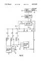
- FIG. 2is a simplified schematic circuit diagram of a heater plate in a thermal inkjet device
- FIG. 3is a schematic circuit diagram of the heater plate of FIG. 2 connected to the detection device of the present invention
- FIG. 4is an alternative embodiment of the detection device of the present invention.
- FIG. 5is a schematic diagram of a multiplex addressing system for activating the particular cells in a printhead array.
- a conventional thermal inkjet printheadhaving a nozzle outlet 3 through which ink from channel or cell 1 is expelled.
- a heater element 4lies in the channel proximate to outlet 3 and is connected to electrode 42 which lies atop heater plate 44.
- Channel 1lies between heater plate 44 and channel plate 46.
- Ink fill hole 7forms a cavity in channel plate 46 so as to allow the channel 1 to fill with ink.
- Thermal printheadsare constructed from a channel plate and a heater plate which form a plurality of channels and heater elements. These printheads are formed on silicon chips by methods as those disclosed in U.S. Pat. No. 4,829,324 to Drake et al which is hereby incorporated by reference.
- FIG. 2illustrates an active thermal ink jet device which has a heater 4 and transistor 8 which are connected in series so as to form a node B.
- Transistor 8is addressed through a gate line 16 which is one of a plurality of gate lines 18.
- Gate line 16also connects to other transistors which are represented by transistor 5 which is connected in series with heater 2 so as to form node A.
- Sink line 20, which is one of a plurality of sink lines 22,connects transistor 8 to a switching device 23 which selectively attaches sink line 20 to a low impedance to ground.
- Sink line 20also connects to other transistors which are represented by transistor 12 which is connected in series with heater 6 so as to form node C.
- FIG. 1illustrates an active thermal ink jet device which has a heater 4 and transistor 8 which are connected in series so as to form a node B.
- Transistor 8is addressed through a gate line 16 which is one of a plurality of gate lines 18.
- Gate line 16also connects to other transistors which are
- Heater 4alone receives a current pulse when 1) gate line 16 is switched to a potential by switching device 21 which turns on all transistors sharing the gate line 16; and 2) sink line 20 is switched by switching device 23 to a low impedance to ground. Being thus activated, heater 4 emits thermal energy which is dissipated into the ink (not shown) contained in cell 1 such that the ink nucleates into a bubble. When the bubble expands, an ink droplet is forced out of the hole 3 whereupon the bubble collapses. Thus, it can be seen how different cells can be activated to release ink.
- FIG. 5serves to illustrate a multiplex system which allows any of the heating elements associated with each cell 100 in a printhead array to be activated by the above-described procedure.
- any one cell(100A, 100B, 100C . . . 100L) is activated when its corresponding gate line (16A, 16B, 16C) and sink line (20A, 20B, 20C, 20D) are activated.
- gate line 16B(which is one of the plurality of gate lines 18) and sink line 20C are activated by the switching devices 21, 23, respectively.
- Thermal inkjet printheadscan have passive or active arrays of heater elements.
- a passive heating elementrequires that each heating element be given a corresponding addressing electrode.
- An example of a passive-type arrayis demonstrated in U.S. Pat. No. 4,829,324 to Drake et al.
- an active array by utilizing various sink and gate lines connected to transistorscan activate heating elements by the method already discussed.
- An example of a thermal printhead having an active arrayis disclosed in U.S. Pat. No. 4,651,164 to Abe et al, the disclosure of which is herein incorporated by reference . Since transistors and sink and gate lines can be provided on the same heating plate as the heating elements, space is saved by utilizing active arrays. However, the present invention is applicable to either active or passive arrays.
- Circuitry to measure heater currentcan be added to the design of FIG. 2 by accessing nodes D and E.
- FIG. 3shows a detecting circuit 40 which is connected to the circuitry depicted in FIG. 2 by accessing nodes D and E. It is noted that nodes D and E are external to the printhead, so no chip modifications are necessitated. It is further noted that the same type of air detector can be used for printheads composed of passive devices since the same nodes are available.
- Detecting circuit 40is shown to have a relatively small-valued sensing element or resistor 30 which is electrically connected to node D which is the line which supplies current to all heaters. Current in the heater 4 is proportional to a drop in potential v(t) across the sensing resistor 30. Sensing resistor 30 is shown to be serially connected to power supply 14.
- a sensing resistor, e.g. resistor 30, which was used as a working modelhad a resistance of 4 ohms which is relatively smaller compared to the 100-300 ohm resistance of the heater 4. However, even smaller values of resistance may well suffice. Further, the resistance contained in power supply 14 and connecting leads 36 and 38 may be sufficient for use as a sensing element.
- Amplifier 34 and capacitor 32are in parallel with sensing resistor 30 and power supply 14. The connection between amplifier 34 and blocking capacitor 32 results in the amplifier 34 being AC coupled.
- bubble detection device 40By providing a sensing resistor 30 having a much smaller resistance than that of heater 4, heater 4 having a resistance of approximately 100 to 300 ohms, bubble detection device 40 has a negligible influence on normal ink jet operations. Thus, detector 40 can operate on-line and test constantly for the presence of a non-collapsing bubble in an ink cell without interrupting the printing operation. One detection circuit 40 is sufficient to serve all cells sharing the same current supply lines as long as the cells can be independently addressed.
- Amplifier 34 of detection circuit 40is connected to calculating means 51 which samples and holds the analog signals received from the amplifier over the pulsed interval and converts analog signals to digital signals.
- Calculating means 51calculates the averaged value of current over the pulsed interval and transmits that value to a microprocessor 50 which compares the averaged value of current in a tested heater with a reference value and activates a reprime signal 70 if the comparison indicates the presence of a non-collapsing bubble (i.e., when the averaged value differs from the reference value by more than the threshold amount).
- the reference value for each cellis determined by taking averaged readings of the current present in each cell's heater when the cell is printing properly. These averaged readings, which are taken over pulse intervals, are then translated to a reference value which is stored in the memory of microprocessor 50. The reference value can then be compared with any subsequent averaged value of current in a heater to determine the presence of a non-collapsing bubble. A difference of more than a programmable or selectable threshold amount between the reference value and the average value indicates the presence of a noncollapsing bubble. When this difference is detected, the microprocessor will activate a reprime signal.
- Heater resistancesare usually relatively uniform so that heater currents can be compared with a single reference value to determine whether a bubble is present. If heaters lack uniformity in resistance, the bubble detection circuit's 40 output could be compared to a set of reference levels stored in the microprocessor's memory.
- Microprocessor 50is programmed to synchronize the detector output with heater pulsing and to disregard detector output for those cells which are not pulsed during a particular cycle.
- FIG. 4shows detecting circuit 40 with switch 56 which can be alternately connected to points X or Y. Should testing of the cells for bubbles be desired, switch 56 connects to point X so that current flows through resistor 30 which is of relatively high resistance when compared to the heating element. When detection circuit 40 is not in a detecting mode, switch 56 connects to point Y so that resistor 30 is bypassed and the operation of the heating element is unaffected. Then, periodically, printing could pause so that the sensing resistor could be switched into the circuit and the detector cycle run. As before, a need for repriming would be sensed and repriming could be automatically activated.
Landscapes
- Ink Jet (AREA)
- Particle Formation And Scattering Control In Inkjet Printers (AREA)
- Investigating Or Analyzing Materials By The Use Of Electric Means (AREA)
Abstract
Description
Claims (18)
Priority Applications (2)
| Application Number | Priority Date | Filing Date | Title |
|---|---|---|---|
| US07/543,497US5072235A (en) | 1990-06-26 | 1990-06-26 | Method and apparatus for the electronic detection of air inside a thermal inkjet printhead |
| JP3147132AJP3025055B2 (en) | 1990-06-26 | 1991-06-19 | Thermal inkjet printer, device and method for detecting non-destructive air bubbles |
Applications Claiming Priority (1)
| Application Number | Priority Date | Filing Date | Title |
|---|---|---|---|
| US07/543,497US5072235A (en) | 1990-06-26 | 1990-06-26 | Method and apparatus for the electronic detection of air inside a thermal inkjet printhead |
Publications (1)
| Publication Number | Publication Date |
|---|---|
| US5072235Atrue US5072235A (en) | 1991-12-10 |
Family
ID=24168313
Family Applications (1)
| Application Number | Title | Priority Date | Filing Date |
|---|---|---|---|
| US07/543,497Expired - LifetimeUS5072235A (en) | 1990-06-26 | 1990-06-26 | Method and apparatus for the electronic detection of air inside a thermal inkjet printhead |
Country Status (2)
| Country | Link |
|---|---|
| US (1) | US5072235A (en) |
| JP (1) | JP3025055B2 (en) |
Cited By (68)
| Publication number | Priority date | Publication date | Assignee | Title |
|---|---|---|---|---|
| EP0622209A3 (en)* | 1993-04-30 | 1995-02-22 | Hewlett Packard Co | Method for detecting and correcting an intrusion of air into a printhead substrate of an ink jet cartridge. |
| US5581284A (en)* | 1994-11-25 | 1996-12-03 | Xerox Corporation | Method of extending the life of a printbar of a color ink jet printer |
| US5721574A (en)* | 1995-12-11 | 1998-02-24 | Xerox Corporation | Ink detecting mechanism for a liquid ink printer |
| US5774159A (en)* | 1996-09-13 | 1998-06-30 | Array Printers Ab | Direct printing method utilizing continuous deflection and a device for accomplishing the method |
| US5818480A (en)* | 1995-02-14 | 1998-10-06 | Array Printers Ab | Method and apparatus to control electrodes in a print unit |
| US5818490A (en)* | 1996-05-02 | 1998-10-06 | Array Printers Ab | Apparatus and method using variable control signals to improve the print quality of an image recording apparatus |
| US5847733A (en)* | 1996-03-22 | 1998-12-08 | Array Printers Ab Publ. | Apparatus and method for increasing the coverage area of a control electrode during direct electrostatic printing |
| US5886713A (en)* | 1995-03-17 | 1999-03-23 | Canon Kabushiki Kaisha | Printhead and printing apparatus using the same |
| US5889542A (en)* | 1996-11-27 | 1999-03-30 | Array Printers Publ. Ab | Printhead structure for direct electrostatic printing |
| US5927547A (en)* | 1996-05-31 | 1999-07-27 | Packard Instrument Company | System for dispensing microvolume quantities of liquids |
| US5956064A (en)* | 1996-10-16 | 1999-09-21 | Array Printers Publ. Ab | Device for enhancing transport of proper polarity toner in direct electrostatic printing |
| US5959648A (en)* | 1996-11-27 | 1999-09-28 | Array Printers Ab | Device and a method for positioning an array of control electrodes in a printhead structure for direct electrostatic printing |
| US5966152A (en)* | 1996-11-27 | 1999-10-12 | Array Printers Ab | Flexible support apparatus for dynamically positioning control units in a printhead structure for direct electrostatic printing |
| US5971526A (en)* | 1996-04-19 | 1999-10-26 | Array Printers Ab | Method and apparatus for reducing cross coupling and dot deflection in an image recording apparatus |
| US5984456A (en)* | 1996-12-05 | 1999-11-16 | Array Printers Ab | Direct printing method utilizing dot deflection and a printhead structure for accomplishing the method |
| US6000786A (en)* | 1995-09-19 | 1999-12-14 | Array Printers Publ. Ab | Method and apparatus for using dual print zones to enhance print quality |
| US6011944A (en)* | 1996-12-05 | 2000-01-04 | Array Printers Ab | Printhead structure for improved dot size control in direct electrostatic image recording devices |
| US6012801A (en)* | 1997-02-18 | 2000-01-11 | Array Printers Ab | Direct printing method with improved control function |
| US6017116A (en)* | 1994-09-19 | 2000-01-25 | Array Printers Ab | Method and device for feeding toner particles in a printer unit |
| US6017115A (en)* | 1997-06-09 | 2000-01-25 | Array Printers Ab | Direct printing method with improved control function |
| US6027206A (en)* | 1997-12-19 | 2000-02-22 | Array Printers Ab | Method and apparatus for cleaning the printhead structure during direct electrostatic printing |
| US6030070A (en)* | 1997-12-19 | 2000-02-29 | Array Printers Ab | Direct electrostatic printing method and apparatus |
| US6062676A (en)* | 1994-12-15 | 2000-05-16 | Array Printers Ab | Serial printing system with direct deposition of powder particles |
| US6070967A (en)* | 1997-12-19 | 2000-06-06 | Array Printers Ab | Method and apparatus for stabilizing an intermediate image receiving member during direct electrostatic printing |
| US6074045A (en)* | 1998-03-04 | 2000-06-13 | Array Printers Ab | Printhead structure in an image recording device |
| US6081283A (en)* | 1998-03-19 | 2000-06-27 | Array Printers Ab | Direct electrostatic printing method and apparatus |
| US6082850A (en)* | 1998-03-19 | 2000-07-04 | Array Printers Ab | Apparatus and method for controlling print density in a direct electrostatic printing apparatus by adjusting toner flow with regard to relative positioning of rows of apertures |
| US6086186A (en)* | 1997-12-19 | 2000-07-11 | Array Printers Ab | Apparatus for positioning a control electrode array in a direct electrostatic printing device |
| US6102525A (en)* | 1998-03-19 | 2000-08-15 | Array Printers Ab | Method and apparatus for controlling the print image density in a direct electrostatic printing apparatus |
| US6102526A (en)* | 1997-12-12 | 2000-08-15 | Array Printers Ab | Image forming method and device utilizing chemically produced toner particles |
| US6109730A (en)* | 1997-03-10 | 2000-08-29 | Array Printers Ab Publ. | Direct printing method with improved control function |
| US6132029A (en)* | 1997-06-09 | 2000-10-17 | Array Printers Ab | Direct printing method with improved control function |
| US6174048B1 (en) | 1998-03-06 | 2001-01-16 | Array Printers Ab | Direct electrostatic printing method and apparatus with apparent enhanced print resolution |
| US6183056B1 (en)* | 1997-10-28 | 2001-02-06 | Hewlett-Packard Company | Thermal inkjet printhead and printer energy control apparatus and method |
| US6199971B1 (en) | 1998-02-24 | 2001-03-13 | Arrray Printers Ab | Direct electrostatic printing method and apparatus with increased print speed |
| US6203759B1 (en) | 1996-05-31 | 2001-03-20 | Packard Instrument Company | Microvolume liquid handling system |
| US6209990B1 (en) | 1997-12-19 | 2001-04-03 | Array Printers Ab | Method and apparatus for coating an intermediate image receiving member to reduce toner bouncing during direct electrostatic printing |
| US6257708B1 (en) | 1997-12-19 | 2001-07-10 | Array Printers Ab | Direct electrostatic printing apparatus and method for controlling dot position using deflection electrodes |
| US6260955B1 (en) | 1996-03-12 | 2001-07-17 | Array Printers Ab | Printing apparatus of toner-jet type |
| US6361147B1 (en) | 1998-06-15 | 2002-03-26 | Array Printers Ab | Direct electrostatic printing method and apparatus |
| US6361148B1 (en) | 1998-06-15 | 2002-03-26 | Array Printers Ab | Direct electrostatic printing method and apparatus |
| EP1211078A1 (en)* | 2000-11-29 | 2002-06-05 | Hewlett-Packard Company | Thermal monitoring system for determining nozzle health |
| US6406132B1 (en) | 1996-03-12 | 2002-06-18 | Array Printers Ab | Printing apparatus of toner jet type having an electrically screened matrix unit |
| EP1125745A3 (en)* | 2000-02-18 | 2002-07-24 | Canon Kabushiki Kaisha | Substrate for ink-jet printing head, ink-jet printing head, ink-jet cartridge, ink-jet printing apparatus, and method for detecting ink in ink-jet printing head |
| US6521187B1 (en) | 1996-05-31 | 2003-02-18 | Packard Instrument Company | Dispensing liquid drops onto porous brittle substrates |
| US6537817B1 (en) | 1993-05-31 | 2003-03-25 | Packard Instrument Company | Piezoelectric-drop-on-demand technology |
| US20030063297A1 (en)* | 2001-09-28 | 2003-04-03 | Simon Dodd | Thermal sense resistor for a replaceable printer component |
| US20030156149A1 (en)* | 2002-02-15 | 2003-08-21 | Samsung Electronics Co., Ltd. | Inkjet printer checking nozzle and providing abnormal nozzle information and method thereof |
| US6655775B1 (en) | 1996-10-15 | 2003-12-02 | Hewlett-Packard Development Company, L.P. | Method and apparatus for drop weight encoding |
| US6682162B2 (en) | 1998-12-14 | 2004-01-27 | Oce-Technologies B.V. | Printing apparatus with measuring circuit for diagnosis of condition of each electromechanical transducer |
| US20040223034A1 (en)* | 2003-05-09 | 2004-11-11 | Feinn James A. | Fluid ejection device with data storage structure |
| US20040239714A1 (en)* | 2003-03-12 | 2004-12-02 | Yusuke Sakagami | Droplet ejection apparatus |
| US20040252151A1 (en)* | 2003-03-27 | 2004-12-16 | Koji Higuchi | Droplet ejection apparatus |
| US20040252144A1 (en)* | 2003-03-27 | 2004-12-16 | Koji Higuchi | Droplet ejection apparatus |
| US20050018017A1 (en)* | 1997-07-15 | 2005-01-27 | Silverbrook Research Pty Ltd | Inkjet nozzle chamber holding two fluids |
| US20050057596A1 (en)* | 2003-04-16 | 2005-03-17 | Osamu Shinkawa | Droplet ejection apparatus and a method of detecting and judging head failure in the same |
| US20050062781A1 (en)* | 2003-03-28 | 2005-03-24 | Osamu Shinkawa | Droplet ejection apparatus and method of detecting ejection failure in droplet ejection heads |
| US20050093917A1 (en)* | 1998-11-09 | 2005-05-05 | Paul Lapstun | Inkjet printhead feedback processing arrangement |
| NL1028177C2 (en)* | 2005-02-03 | 2006-08-07 | Oce Tech Bv | Method for an inkjet printer and a printer adapted for application of this method. |
| EP1591262A3 (en)* | 2004-04-28 | 2007-07-11 | Ricoh Company | Ink jet recording apparatus, controlling method for computer program and a computer readable storage medium |
| US20080024565A1 (en)* | 2006-07-27 | 2008-01-31 | Smith Mark A | Printing systems, inkjet pens, and methods for priming |
| WO2010100611A1 (en)* | 2009-03-05 | 2010-09-10 | Koninklijke Philips Electronics N.V. | Sensor for detecting bubbles in a liquid flowing through a flow path |
| US8393714B2 (en) | 1997-07-15 | 2013-03-12 | Zamtec Ltd | Printhead with fluid flow control |
| WO2015167561A1 (en)* | 2014-04-30 | 2015-11-05 | Hewlett-Packard Development Company, L.P. | Determining a time instant for an impedance measurement |
| WO2017073545A1 (en) | 2015-10-28 | 2017-05-04 | Funai Electric Co., Ltd. | Fluid printhead and method of controlling operation of plurality of drive elements of printhead |
| USD905740S1 (en) | 2017-09-25 | 2020-12-22 | Xerox Corporation | Printer machine user interface screen with a set of icons |
| EP3988145A1 (en)* | 2020-10-23 | 2022-04-27 | Honeywell International Inc. | Sensors and methods for air bubble detection |
| US20230077341A1 (en)* | 2021-09-13 | 2023-03-16 | Funai Electric Co., Ltd. | Fluid Sense Circuit with Variable Sensitivity |
Families Citing this family (2)
| Publication number | Priority date | Publication date | Assignee | Title |
|---|---|---|---|---|
| US8833921B2 (en) | 2010-07-30 | 2014-09-16 | Ricoh Company, Limited | Thin-film forming apparatus, thin-film forming method, piezoelectric-element forming method, droplet discharging head, and ink-jet recording apparatus |
| CN106304834B (en)* | 2014-04-25 | 2018-12-14 | 惠普发展公司有限责任合伙企业 | For assessing the method for nozzle situation, the print head and printer of printer |
Citations (9)
| Publication number | Priority date | Publication date | Assignee | Title |
|---|---|---|---|---|
| US4466005A (en)* | 1981-07-27 | 1984-08-14 | Sharp Kabushiki Kaisha | Air bubble removing system in a printer head of an ink jet system printer of the ink on demand type |
| US4518974A (en)* | 1982-09-21 | 1985-05-21 | Ricoh Company, Ltd. | Ink jet air removal system |
| US4550327A (en)* | 1982-01-08 | 1985-10-29 | Canon Kabushiki Kaisha | Device for discharging liquid droplets |
| US4590482A (en)* | 1983-12-14 | 1986-05-20 | Hewlett-Packard Company | Nozzle test apparatus and method for thermal ink jet systems |
| US4595935A (en)* | 1984-08-14 | 1986-06-17 | Ncr Canada Ltd. | System for detecting defective thermal printhead elements |
| US4625220A (en)* | 1983-11-10 | 1986-11-25 | Canon Kabushiki Kaisha | Monitoring apparatus for liquid jet recording head |
| US4695852A (en)* | 1985-10-31 | 1987-09-22 | Ing. C. Olivetti & C., S.P.A. | Ink jet print head |
| US4774526A (en)* | 1985-09-14 | 1988-09-27 | Kabushiki Kaisha Sato | Fault detection circuit for a thermal print head |
| US4996487A (en)* | 1989-04-24 | 1991-02-26 | International Business Machines Corporation | Apparatus for detecting failure of thermal heaters in ink jet printers |
- 1990
- 1990-06-26USUS07/543,497patent/US5072235A/ennot_activeExpired - Lifetime
- 1991
- 1991-06-19JPJP3147132Apatent/JP3025055B2/ennot_activeExpired - Fee Related
Patent Citations (9)
| Publication number | Priority date | Publication date | Assignee | Title |
|---|---|---|---|---|
| US4466005A (en)* | 1981-07-27 | 1984-08-14 | Sharp Kabushiki Kaisha | Air bubble removing system in a printer head of an ink jet system printer of the ink on demand type |
| US4550327A (en)* | 1982-01-08 | 1985-10-29 | Canon Kabushiki Kaisha | Device for discharging liquid droplets |
| US4518974A (en)* | 1982-09-21 | 1985-05-21 | Ricoh Company, Ltd. | Ink jet air removal system |
| US4625220A (en)* | 1983-11-10 | 1986-11-25 | Canon Kabushiki Kaisha | Monitoring apparatus for liquid jet recording head |
| US4590482A (en)* | 1983-12-14 | 1986-05-20 | Hewlett-Packard Company | Nozzle test apparatus and method for thermal ink jet systems |
| US4595935A (en)* | 1984-08-14 | 1986-06-17 | Ncr Canada Ltd. | System for detecting defective thermal printhead elements |
| US4774526A (en)* | 1985-09-14 | 1988-09-27 | Kabushiki Kaisha Sato | Fault detection circuit for a thermal print head |
| US4695852A (en)* | 1985-10-31 | 1987-09-22 | Ing. C. Olivetti & C., S.P.A. | Ink jet print head |
| US4996487A (en)* | 1989-04-24 | 1991-02-26 | International Business Machines Corporation | Apparatus for detecting failure of thermal heaters in ink jet printers |
Non-Patent Citations (2)
| Title |
|---|
| Harmon et al.; Integrating the Printhead into the HP Deskjet Printer; H P Journal, Oct. 1988, pp. 62 66.* |
| Harmon et al.; Integrating the Printhead into the HP Deskjet Printer; H-P Journal, Oct. 1988, pp. 62-66. |
Cited By (124)
| Publication number | Priority date | Publication date | Assignee | Title |
|---|---|---|---|---|
| EP0622209A3 (en)* | 1993-04-30 | 1995-02-22 | Hewlett Packard Co | Method for detecting and correcting an intrusion of air into a printhead substrate of an ink jet cartridge. |
| US6537817B1 (en) | 1993-05-31 | 2003-03-25 | Packard Instrument Company | Piezoelectric-drop-on-demand technology |
| US6017116A (en)* | 1994-09-19 | 2000-01-25 | Array Printers Ab | Method and device for feeding toner particles in a printer unit |
| US5581284A (en)* | 1994-11-25 | 1996-12-03 | Xerox Corporation | Method of extending the life of a printbar of a color ink jet printer |
| US6062676A (en)* | 1994-12-15 | 2000-05-16 | Array Printers Ab | Serial printing system with direct deposition of powder particles |
| US5818480A (en)* | 1995-02-14 | 1998-10-06 | Array Printers Ab | Method and apparatus to control electrodes in a print unit |
| US5886713A (en)* | 1995-03-17 | 1999-03-23 | Canon Kabushiki Kaisha | Printhead and printing apparatus using the same |
| US6000786A (en)* | 1995-09-19 | 1999-12-14 | Array Printers Publ. Ab | Method and apparatus for using dual print zones to enhance print quality |
| US5721574A (en)* | 1995-12-11 | 1998-02-24 | Xerox Corporation | Ink detecting mechanism for a liquid ink printer |
| US6406132B1 (en) | 1996-03-12 | 2002-06-18 | Array Printers Ab | Printing apparatus of toner jet type having an electrically screened matrix unit |
| US6260955B1 (en) | 1996-03-12 | 2001-07-17 | Array Printers Ab | Printing apparatus of toner-jet type |
| US5847733A (en)* | 1996-03-22 | 1998-12-08 | Array Printers Ab Publ. | Apparatus and method for increasing the coverage area of a control electrode during direct electrostatic printing |
| US5971526A (en)* | 1996-04-19 | 1999-10-26 | Array Printers Ab | Method and apparatus for reducing cross coupling and dot deflection in an image recording apparatus |
| US5818490A (en)* | 1996-05-02 | 1998-10-06 | Array Printers Ab | Apparatus and method using variable control signals to improve the print quality of an image recording apparatus |
| US6112605A (en)* | 1996-05-31 | 2000-09-05 | Packard Instrument Company | Method for dispensing and determining a microvolume of sample liquid |
| US5927547A (en)* | 1996-05-31 | 1999-07-27 | Packard Instrument Company | System for dispensing microvolume quantities of liquids |
| US6083762A (en)* | 1996-05-31 | 2000-07-04 | Packard Instruments Company | Microvolume liquid handling system |
| US6203759B1 (en) | 1996-05-31 | 2001-03-20 | Packard Instrument Company | Microvolume liquid handling system |
| US6079283A (en)* | 1996-05-31 | 2000-06-27 | Packard Instruments Comapny | Method for aspirating sample liquid into a dispenser tip and thereafter ejecting droplets therethrough |
| US6592825B2 (en) | 1996-05-31 | 2003-07-15 | Packard Instrument Company, Inc. | Microvolume liquid handling system |
| US6521187B1 (en) | 1996-05-31 | 2003-02-18 | Packard Instrument Company | Dispensing liquid drops onto porous brittle substrates |
| US6422431B2 (en) | 1996-05-31 | 2002-07-23 | Packard Instrument Company, Inc. | Microvolume liquid handling system |
| US5774159A (en)* | 1996-09-13 | 1998-06-30 | Array Printers Ab | Direct printing method utilizing continuous deflection and a device for accomplishing the method |
| US6655775B1 (en) | 1996-10-15 | 2003-12-02 | Hewlett-Packard Development Company, L.P. | Method and apparatus for drop weight encoding |
| US5956064A (en)* | 1996-10-16 | 1999-09-21 | Array Printers Publ. Ab | Device for enhancing transport of proper polarity toner in direct electrostatic printing |
| US5889542A (en)* | 1996-11-27 | 1999-03-30 | Array Printers Publ. Ab | Printhead structure for direct electrostatic printing |
| US5966152A (en)* | 1996-11-27 | 1999-10-12 | Array Printers Ab | Flexible support apparatus for dynamically positioning control units in a printhead structure for direct electrostatic printing |
| US5959648A (en)* | 1996-11-27 | 1999-09-28 | Array Printers Ab | Device and a method for positioning an array of control electrodes in a printhead structure for direct electrostatic printing |
| US6011944A (en)* | 1996-12-05 | 2000-01-04 | Array Printers Ab | Printhead structure for improved dot size control in direct electrostatic image recording devices |
| US5984456A (en)* | 1996-12-05 | 1999-11-16 | Array Printers Ab | Direct printing method utilizing dot deflection and a printhead structure for accomplishing the method |
| US6012801A (en)* | 1997-02-18 | 2000-01-11 | Array Printers Ab | Direct printing method with improved control function |
| US6176568B1 (en) | 1997-02-18 | 2001-01-23 | Array Printers Ab | Direct printing method with improved control function |
| US6109730A (en)* | 1997-03-10 | 2000-08-29 | Array Printers Ab Publ. | Direct printing method with improved control function |
| US6017115A (en)* | 1997-06-09 | 2000-01-25 | Array Printers Ab | Direct printing method with improved control function |
| US6132029A (en)* | 1997-06-09 | 2000-10-17 | Array Printers Ab | Direct printing method with improved control function |
| US7934808B2 (en) | 1997-07-15 | 2011-05-03 | Silverbrook Research Pty Ltd | Inkjet printhead with nozzle chambers each holding two fluids |
| US7699440B2 (en) | 1997-07-15 | 2010-04-20 | Silverbrook Research Pty Ltd | Inkjet printhead with heater element close to drive circuits |
| US8393714B2 (en) | 1997-07-15 | 2013-03-12 | Zamtec Ltd | Printhead with fluid flow control |
| US20090160910A1 (en)* | 1997-07-15 | 2009-06-25 | Silverbrook Research Pty Ltd | Inkjet printhead with heater element close to drive circuits |
| US20090278897A1 (en)* | 1997-07-15 | 2009-11-12 | Silverbrook Research Pty Ltd | Inkjet Printhead With Nozzle Chambers Each Holding Two Fluids |
| US20090122116A1 (en)* | 1997-07-15 | 2009-05-14 | Silverbrook Research Pty Ltd. | Fluid ejection device with resistive element close to drive circuits |
| US20090124029A1 (en)* | 1997-07-15 | 2009-05-14 | Silverbrook Research Pty Ltd. | Method of fabricating resistor and proximate drive transistor for a printhead |
| US7578582B2 (en)* | 1997-07-15 | 2009-08-25 | Silverbrook Research Pty Ltd | Inkjet nozzle chamber holding two fluids |
| US20080252691A9 (en)* | 1997-07-15 | 2008-10-16 | Silverbrook Research Pty Ltd | Inkjet nozzle chamber holding two fluids |
| US20050018017A1 (en)* | 1997-07-15 | 2005-01-27 | Silverbrook Research Pty Ltd | Inkjet nozzle chamber holding two fluids |
| US7708381B2 (en) | 1997-07-15 | 2010-05-04 | Silverbrook Research Pty Ltd | Fluid ejection device with resistive element close to drive circuits |
| US20100201750A1 (en)* | 1997-07-15 | 2010-08-12 | Silverbrook Research Pty Ltd | Fluid ejection device with overlapping firing chamber and drive fet |
| US7905574B2 (en) | 1997-07-15 | 2011-03-15 | Silverbrook Research Pty Ltd | Method of fabricating resistor and proximate drive transistor for a printhead |
| US7992968B2 (en) | 1997-07-15 | 2011-08-09 | Silverbrook Research Pty Ltd | Fluid ejection device with overlapping firing chamber and drive FET |
| US6183056B1 (en)* | 1997-10-28 | 2001-02-06 | Hewlett-Packard Company | Thermal inkjet printhead and printer energy control apparatus and method |
| US6102526A (en)* | 1997-12-12 | 2000-08-15 | Array Printers Ab | Image forming method and device utilizing chemically produced toner particles |
| US6030070A (en)* | 1997-12-19 | 2000-02-29 | Array Printers Ab | Direct electrostatic printing method and apparatus |
| US6086186A (en)* | 1997-12-19 | 2000-07-11 | Array Printers Ab | Apparatus for positioning a control electrode array in a direct electrostatic printing device |
| US6027206A (en)* | 1997-12-19 | 2000-02-22 | Array Printers Ab | Method and apparatus for cleaning the printhead structure during direct electrostatic printing |
| US6257708B1 (en) | 1997-12-19 | 2001-07-10 | Array Printers Ab | Direct electrostatic printing apparatus and method for controlling dot position using deflection electrodes |
| US6209990B1 (en) | 1997-12-19 | 2001-04-03 | Array Printers Ab | Method and apparatus for coating an intermediate image receiving member to reduce toner bouncing during direct electrostatic printing |
| US6070967A (en)* | 1997-12-19 | 2000-06-06 | Array Printers Ab | Method and apparatus for stabilizing an intermediate image receiving member during direct electrostatic printing |
| US6199971B1 (en) | 1998-02-24 | 2001-03-13 | Arrray Printers Ab | Direct electrostatic printing method and apparatus with increased print speed |
| US6074045A (en)* | 1998-03-04 | 2000-06-13 | Array Printers Ab | Printhead structure in an image recording device |
| US6174048B1 (en) | 1998-03-06 | 2001-01-16 | Array Printers Ab | Direct electrostatic printing method and apparatus with apparent enhanced print resolution |
| US6081283A (en)* | 1998-03-19 | 2000-06-27 | Array Printers Ab | Direct electrostatic printing method and apparatus |
| US6102525A (en)* | 1998-03-19 | 2000-08-15 | Array Printers Ab | Method and apparatus for controlling the print image density in a direct electrostatic printing apparatus |
| US6082850A (en)* | 1998-03-19 | 2000-07-04 | Array Printers Ab | Apparatus and method for controlling print density in a direct electrostatic printing apparatus by adjusting toner flow with regard to relative positioning of rows of apertures |
| US6361147B1 (en) | 1998-06-15 | 2002-03-26 | Array Printers Ab | Direct electrostatic printing method and apparatus |
| US6361148B1 (en) | 1998-06-15 | 2002-03-26 | Array Printers Ab | Direct electrostatic printing method and apparatus |
| US20050093917A1 (en)* | 1998-11-09 | 2005-05-05 | Paul Lapstun | Inkjet printhead feedback processing arrangement |
| US7118186B2 (en)* | 1998-11-09 | 2006-10-10 | Silverbrook Research Pty Ltd | Inkjet printhead feedback processing arrangement |
| US6682162B2 (en) | 1998-12-14 | 2004-01-27 | Oce-Technologies B.V. | Printing apparatus with measuring circuit for diagnosis of condition of each electromechanical transducer |
| US6652053B2 (en) | 2000-02-18 | 2003-11-25 | Canon Kabushiki Kaisha | Substrate for ink-jet printing head, ink-jet printing head, ink-jet cartridge, ink-jet printing apparatus, and method for detecting ink in ink-jet printing head |
| EP1125745A3 (en)* | 2000-02-18 | 2002-07-24 | Canon Kabushiki Kaisha | Substrate for ink-jet printing head, ink-jet printing head, ink-jet cartridge, ink-jet printing apparatus, and method for detecting ink in ink-jet printing head |
| EP1211078A1 (en)* | 2000-11-29 | 2002-06-05 | Hewlett-Packard Company | Thermal monitoring system for determining nozzle health |
| US6460964B2 (en) | 2000-11-29 | 2002-10-08 | Hewlett-Packard Company | Thermal monitoring system for determining nozzle health |
| WO2003029006A3 (en)* | 2001-09-28 | 2004-09-23 | Hewlett Packard Co | Variable thermal sense resistor for a replaceable printer component |
| US7128401B2 (en) | 2001-09-28 | 2006-10-31 | Hewlett-Packard Development Company, L.P. | Thermal sense resistor for a replaceable printer component |
| US20050264595A1 (en)* | 2001-09-28 | 2005-12-01 | Simon Dodd | Thermal sense resistor for a replaceable printer component |
| CN100415529C (en)* | 2001-09-28 | 2008-09-03 | 惠普公司 | Thermal sense resistor for a replaceable printer component |
| US20030063297A1 (en)* | 2001-09-28 | 2003-04-03 | Simon Dodd | Thermal sense resistor for a replaceable printer component |
| US7036903B2 (en)* | 2002-02-15 | 2006-05-02 | Samsung Electronics Co., Ltd. | Inkjet printer checking nozzle and providing abnormal nozzle information and method thereof |
| US20030156149A1 (en)* | 2002-02-15 | 2003-08-21 | Samsung Electronics Co., Ltd. | Inkjet printer checking nozzle and providing abnormal nozzle information and method thereof |
| US20040239714A1 (en)* | 2003-03-12 | 2004-12-02 | Yusuke Sakagami | Droplet ejection apparatus |
| US7328960B2 (en) | 2003-03-12 | 2008-02-12 | Seiko Epson Corporation | Droplet ejection apparatus |
| US20040252151A1 (en)* | 2003-03-27 | 2004-12-16 | Koji Higuchi | Droplet ejection apparatus |
| US7328962B2 (en) | 2003-03-27 | 2008-02-12 | Seiko Epson Corporation | Droplet ejection apparatus |
| US7311373B2 (en)* | 2003-03-27 | 2007-12-25 | Seiko Epson Corporation | Droplet ejection apparatus including recovery processing with a standby power supply |
| US20040252144A1 (en)* | 2003-03-27 | 2004-12-16 | Koji Higuchi | Droplet ejection apparatus |
| US7341325B2 (en) | 2003-03-28 | 2008-03-11 | Seiko Epson Corporation | Droplet ejection apparatus and method of detecting ejection failure in droplet ejection heads |
| US20050062781A1 (en)* | 2003-03-28 | 2005-03-24 | Osamu Shinkawa | Droplet ejection apparatus and method of detecting ejection failure in droplet ejection heads |
| US7387356B2 (en) | 2003-04-16 | 2008-06-17 | Seiko Epson Corporation | Droplet ejection apparatus and a method of detecting and judging head failure in the same |
| US20080088657A1 (en)* | 2003-04-16 | 2008-04-17 | Osamu Shinkawa | Droplet ejection apparatus and a method of detecting and judging head failure in the same |
| US7566109B2 (en) | 2003-04-16 | 2009-07-28 | Seiko Epson Corporation | Droplet ejection apparatus and a method of detecting and judging head failure in the same |
| US20050057596A1 (en)* | 2003-04-16 | 2005-03-17 | Osamu Shinkawa | Droplet ejection apparatus and a method of detecting and judging head failure in the same |
| US7249825B2 (en) | 2003-05-09 | 2007-07-31 | Hewlett-Packard Development Company, L.P. | Fluid ejection device with data storage structure |
| US20040223034A1 (en)* | 2003-05-09 | 2004-11-11 | Feinn James A. | Fluid ejection device with data storage structure |
| EP1591262A3 (en)* | 2004-04-28 | 2007-07-11 | Ricoh Company | Ink jet recording apparatus, controlling method for computer program and a computer readable storage medium |
| NL1028177C2 (en)* | 2005-02-03 | 2006-08-07 | Oce Tech Bv | Method for an inkjet printer and a printer adapted for application of this method. |
| EP1688263A1 (en)* | 2005-02-03 | 2006-08-09 | Océ-Technologies B.V. | Method for an inkjet printer and a printer which has been modified for this method to be applied |
| US7988265B2 (en) | 2006-07-27 | 2011-08-02 | Hewlett-Packard Development Company, L.P. | Air detection in inkjet pens |
| US20080024565A1 (en)* | 2006-07-27 | 2008-01-31 | Smith Mark A | Printing systems, inkjet pens, and methods for priming |
| WO2010100611A1 (en)* | 2009-03-05 | 2010-09-10 | Koninklijke Philips Electronics N.V. | Sensor for detecting bubbles in a liquid flowing through a flow path |
| CN102341137A (en)* | 2009-03-05 | 2012-02-01 | 皇家飞利浦电子股份有限公司 | Sensor for detecting bubbles in a liquid flowing through a flow path |
| JP2012519529A (en)* | 2009-03-05 | 2012-08-30 | コーニンクレッカ フィリップス エレクトロニクス エヌ ヴィ | Sensor that detects bubbles in the liquid flowing through the flow path |
| RU2521731C2 (en)* | 2009-03-05 | 2014-07-10 | Конинклейке Филипс Электроникс Н.В. | Sensor for detection of bubbles in liquid flowing along flow path |
| US8794081B2 (en) | 2009-03-05 | 2014-08-05 | Koninklijke Philips N.V. | Sensor for detecting bubbles in a liquid flowing through a flow path |
| CN102341137B (en)* | 2009-03-05 | 2014-10-29 | 皇家飞利浦电子股份有限公司 | Sensor for detecting bubbles in a liquid flowing through a flow path |
| US9776395B2 (en) | 2014-04-30 | 2017-10-03 | Hewlett-Packard Development Company, L.P. | Determining a time instant for an impedance measurement |
| US10220609B2 (en) | 2014-04-30 | 2019-03-05 | Hewlett-Packard Development Company, L.P. | Impedance measurements at time instants |
| TWI574850B (en)* | 2014-04-30 | 2017-03-21 | 惠普發展公司有限責任合夥企業 | Method for determining an issue in an inkjet nozzle, print head, and printer |
| CN106255597A (en)* | 2014-04-30 | 2016-12-21 | 惠普发展公司有限责任合伙企业 | Determine the moment of impedance measurement |
| CN106255597B (en)* | 2014-04-30 | 2018-02-06 | 惠普发展公司有限责任合伙企业 | Method, printhead and printer for determining problems in inkjet nozzles |
| WO2015167561A1 (en)* | 2014-04-30 | 2015-11-05 | Hewlett-Packard Development Company, L.P. | Determining a time instant for an impedance measurement |
| US9815278B2 (en) | 2015-10-28 | 2017-11-14 | Funai Electric Co., Ltd. | Fluid printhead |
| US9656464B1 (en) | 2015-10-28 | 2017-05-23 | Funai Electric Co., Ltd. | Fluid printhead |
| CN108136774A (en)* | 2015-10-28 | 2018-06-08 | 船井电机株式会社 | The method of the operation of multiple driving elements of fluid print head and control print head |
| WO2017073545A1 (en) | 2015-10-28 | 2017-05-04 | Funai Electric Co., Ltd. | Fluid printhead and method of controlling operation of plurality of drive elements of printhead |
| EP3368320A4 (en)* | 2015-10-28 | 2019-06-12 | Funai Electric Co., Ltd. | FLUID PRINTING HEAD AND METHOD OF CONTROLLING OPERATION OF A PLURALITY OF PRINT HEAD DRIVING ELEMENTS |
| USD905740S1 (en) | 2017-09-25 | 2020-12-22 | Xerox Corporation | Printer machine user interface screen with a set of icons |
| EP3988145A1 (en)* | 2020-10-23 | 2022-04-27 | Honeywell International Inc. | Sensors and methods for air bubble detection |
| US20220128418A1 (en)* | 2020-10-23 | 2022-04-28 | Honeywell International Inc. | Sensors, methods, and computer program products for air bubble detection |
| US11860042B2 (en)* | 2020-10-23 | 2024-01-02 | Honeywell International Inc. | Sensors, methods, and computer program products for air bubble detection |
| US20240085249A1 (en)* | 2020-10-23 | 2024-03-14 | Honeywell International Inc. | Sensors, methods, and computer program products for air bubble detection |
| US12196621B2 (en)* | 2020-10-23 | 2025-01-14 | Honeywell International Inc. | Sensors, methods, and computer program products for air bubble detection |
| EP4478004A3 (en)* | 2020-10-23 | 2025-03-12 | Honeywell International Inc. | Sensors and methods for air bubble detection |
| US20230077341A1 (en)* | 2021-09-13 | 2023-03-16 | Funai Electric Co., Ltd. | Fluid Sense Circuit with Variable Sensitivity |
| US11686696B2 (en)* | 2021-09-13 | 2023-06-27 | Funai Electric Co., Ltd. | Fluid sense circuit with variable sensitivity |
Also Published As
| Publication number | Publication date |
|---|---|
| JP3025055B2 (en) | 2000-03-27 |
| JPH04232753A (en) | 1992-08-21 |
Similar Documents
| Publication | Publication Date | Title |
|---|---|---|
| US5072235A (en) | Method and apparatus for the electronic detection of air inside a thermal inkjet printhead | |
| US10717279B2 (en) | Printhead condition detection system | |
| EP0440110B1 (en) | Ink near-end detecting device | |
| EP2925528B1 (en) | Fluid ejection device with integrated ink level sensor | |
| US6007173A (en) | Ink status system for a liquid ink printer | |
| KR970011234B1 (en) | Ink-jet recording head and ink-jet recording apparatus | |
| US8024968B2 (en) | Apparatus and method for detecting ink in a reservoir | |
| US8287082B2 (en) | Method of detecting discharging state of inkjet recording head | |
| US9862187B1 (en) | Inkjet printhead temperature sensing at multiple locations | |
| US5943069A (en) | Ink jet recording head and apparatus in which recording is controlled in accordance with calculations involving a measured resistance | |
| JP4565676B2 (en) | Liquid ink print head with programmable temperature sensing device, thermal ink jet printer with the same, and method for adjusting the output of the temperature sensing device | |
| US6871929B2 (en) | System and method for optimizing temperature operating ranges for a thermal inkjet printhead | |
| JPH09314861A (en) | Inkjet recording device and inkjet unit | |
| KR100252443B1 (en) | Image transmission apparatus and operation inspection method of the apparatus | |
| JP3420268B2 (en) | Ink jet device | |
| JP2862517B2 (en) | ink cartridge | |
| JPH02231145A (en) | Ink remainder detector, ink jet head cartridge with the same detector and ink jet recorder mounting the same cartridge | |
| US6109714A (en) | Ink-jet printing apparatus with a system for detecting remaining amount of ink | |
| JPH0550590A (en) | Liquid jet recorder | |
| JP2887258B2 (en) | Thermal inkjet head | |
| JPH08290581A (en) | Ink supplying device and recorder using the same | |
| JP2752676B2 (en) | Liquid jet recording apparatus and liquid jet recording head mounted thereon | |
| AU747257B2 (en) | Ink jet recording apparatus | |
| JP2001010057A (en) | Recording device and recording method | |
| JP2841662B2 (en) | Ink tank for inkjet recording device |
Legal Events
| Date | Code | Title | Description |
|---|---|---|---|
| AS | Assignment | Owner name:XEROX CORPORATION, STAMFORD, CT A CORP. OF NY Free format text:ASSIGNMENT OF ASSIGNORS INTEREST.;ASSIGNORS:SLOWIK, JOHN H.;POND, STEPHEN F.;REEL/FRAME:005364/0089;SIGNING DATES FROM 19900619 TO 19900625 | |
| STCF | Information on status: patent grant | Free format text:PATENTED CASE | |
| FEPP | Fee payment procedure | Free format text:PAYOR NUMBER ASSIGNED (ORIGINAL EVENT CODE: ASPN); ENTITY STATUS OF PATENT OWNER: LARGE ENTITY | |
| FPAY | Fee payment | Year of fee payment:4 | |
| FPAY | Fee payment | Year of fee payment:8 | |
| AS | Assignment | Owner name:BANK ONE, NA, AS ADMINISTRATIVE AGENT, ILLINOIS Free format text:SECURITY INTEREST;ASSIGNOR:XEROX CORPORATION;REEL/FRAME:013153/0001 Effective date:20020621 | |
| FPAY | Fee payment | Year of fee payment:12 | |
| AS | Assignment | Owner name:JPMORGAN CHASE BANK, AS COLLATERAL AGENT, TEXAS Free format text:SECURITY AGREEMENT;ASSIGNOR:XEROX CORPORATION;REEL/FRAME:015134/0476 Effective date:20030625 Owner name:JPMORGAN CHASE BANK, AS COLLATERAL AGENT,TEXAS Free format text:SECURITY AGREEMENT;ASSIGNOR:XEROX CORPORATION;REEL/FRAME:015134/0476 Effective date:20030625 | |
| AS | Assignment | Owner name:XEROX CORPORATION, CONNECTICUT Free format text:RELEASE BY SECURED PARTY;ASSIGNOR:JPMORGAN CHASE BANK, N.A. AS SUCCESSOR-IN-INTEREST ADMINISTRATIVE AGENT AND COLLATERAL AGENT TO JPMORGAN CHASE BANK;REEL/FRAME:066728/0193 Effective date:20220822 |