US5071431A - Suture rings for heart valves and method of securing suture rings to heart valves - Google Patents
Suture rings for heart valves and method of securing suture rings to heart valvesDownload PDFInfo
- Publication number
- US5071431A US5071431AUS07/610,084US61008490AUS5071431AUS 5071431 AUS5071431 AUS 5071431AUS 61008490 AUS61008490 AUS 61008490AUS 5071431 AUS5071431 AUS 5071431A
- Authority
- US
- United States
- Prior art keywords
- ring
- sewing cuff
- capturing
- ribbon
- edge
- Prior art date
- Legal status (The legal status is an assumption and is not a legal conclusion. Google has not performed a legal analysis and makes no representation as to the accuracy of the status listed.)
- Expired - Lifetime
Links
Images


Classifications
- A—HUMAN NECESSITIES
- A61—MEDICAL OR VETERINARY SCIENCE; HYGIENE
- A61F—FILTERS IMPLANTABLE INTO BLOOD VESSELS; PROSTHESES; DEVICES PROVIDING PATENCY TO, OR PREVENTING COLLAPSING OF, TUBULAR STRUCTURES OF THE BODY, e.g. STENTS; ORTHOPAEDIC, NURSING OR CONTRACEPTIVE DEVICES; FOMENTATION; TREATMENT OR PROTECTION OF EYES OR EARS; BANDAGES, DRESSINGS OR ABSORBENT PADS; FIRST-AID KITS
- A61F2/00—Filters implantable into blood vessels; Prostheses, i.e. artificial substitutes or replacements for parts of the body; Appliances for connecting them with the body; Devices providing patency to, or preventing collapsing of, tubular structures of the body, e.g. stents
- A61F2/02—Prostheses implantable into the body
- A61F2/24—Heart valves ; Vascular valves, e.g. venous valves; Heart implants, e.g. passive devices for improving the function of the native valve or the heart muscle; Transmyocardial revascularisation [TMR] devices; Valves implantable in the body
- A61F2/2409—Support rings therefor, e.g. for connecting valves to tissue
- Y—GENERAL TAGGING OF NEW TECHNOLOGICAL DEVELOPMENTS; GENERAL TAGGING OF CROSS-SECTIONAL TECHNOLOGIES SPANNING OVER SEVERAL SECTIONS OF THE IPC; TECHNICAL SUBJECTS COVERED BY FORMER USPC CROSS-REFERENCE ART COLLECTIONS [XRACs] AND DIGESTS
- Y10—TECHNICAL SUBJECTS COVERED BY FORMER USPC
- Y10S—TECHNICAL SUBJECTS COVERED BY FORMER USPC CROSS-REFERENCE ART COLLECTIONS [XRACs] AND DIGESTS
- Y10S623/00—Prosthesis, i.e. artificial body members, parts thereof, or aids and accessories therefor
- Y10S623/90—Stent for heart valve
Definitions
- Our inventionis directed to an improved suture ring for a prosthetic heart valve and to a method and apparatus for securing the suture ring to the heart valve.
- PyroliteTMa trademark of Carbomedics, Inc., the assignee of our present invention.
- Pyrolitic carbonis employed because of its unusual nonthrombogenic properties. Human blood does not readily coagulate on contact with it. Moreover, it is lightweight, hard and quite strong.
- a standard implantable mechanical heart valveusually has an annular valve housing or body to provide a passageway for blood. Occluders are mounted in the annular body and open or close the blood flow passageway. Usually there are one or two occluders, but occasionally triple occluder configurations have been proposed. On the outside of the valve body there is usually an external, circumferential surface configured as a groove. The purpose of this groove is to facilitate attachment of a suture ring to the valve body.
- the suture ringis used to sew the heart valve to the patient's heart tissue.
- the ringgenerally comprises a knit fabric tube which is rolled into a toroidal form and which is secured about the heart valve body in the circumferential groove.
- Various methods and apparatushave been proposed for securing the suture ring to the heart valve. It is known, for instance, to bind the ring into the groove with a plastic thread. It has also been proposed to form a rotatable suture on the heart valve using heat shrinkable plastic material, as disclosed in U.S. Pat. No. 3,781,969. U.S. Pat. No. 3,491,376 suggests that a suture ring should be formed as a separate sub-assembly which should then be attached to the heart valve.
- the suture ringis described as including a resilient annular member which is temporarily deformed, so as to snap onto the valve body.
- U.S. Pat. No. 3,579,642proposes the use of metal snap rings which must be radially expanded to place the suture ring about the valve body. In such fabrication techniques, however, there is a risk of potential damage to the suture rings when the ring is mechanically expanded to place it about the valve body.
- Magladryproposed a two-part suture ring comprising the knit fabric and an internal crescent-shaped ring which would be deformed inwardly by electromagnetic forming to clamp the heart valve while permitting relative rotation between the suture ring and the heart valve.
- a suture ringcomprised of essentially three parts: a stiffening ring which fits over an outer surface of a heart valve; a knit fabric sewing cuff attached to the stiffening ring, and a locking ring for securing the stiffening ring to the heart valve.
- our preferred embodimentcomprises a locking ring which is generally crescent-shaped in cross-section.
- the locking ringis a split ring configuration so that it can be easily placed within the stiffening ring without deforming the stiffening ring and without plastic deformation or damage to the locking ring. This radial expansion or contraction is a first mode of deformation for the locking ring.
- the stiffening ring and the valve bodycan be locked together because the locking ring is capable of deforming in a second mode.
- the locking ringdeforms by a slight flattening of the crescent cross-section of the ring. This second mode of deformation resists uncoupling of the stiffening ring and the heart valve.
- the suture rings described hereinshare the common characteristic that they have two modes of deformation: one mode for assembly of the locking ring and the heart valve and second mode for the assembly of the suture ring combination and the heart valve.
- Another object of our inventionis to provide a suture ring comprising three elements: a sewing cuff, a stiffening ring and locking ring.
- Another object of our inventionis to provide such a locking ring wherein one mode of deformation is useful in assembling a suture ring combination and a second mode of locking ring deformation is useful in assembling the suture ring combination and the heart valve.
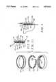
- FIG. 1is a perspective view of a prosthetic mechanical heart valve with a suture ring.
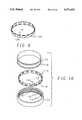
- FIG. 2is an exploded perspective view of a stiffening ring, locking ring and heart valve annulus according to our present invention.
- FIG. 3is a cross-section of the three components of FIG. 2 taken along line 3--3 and showing the components an assembled configuration.
- FIG. 4is a cross-sectional view of the components of FIG. 2 taken along line 3--3, showing the components during assembly.
- FIGS. 5-11are alternative embodiments of our invention.
- FIG. 12is a perspective view of a tool for assembling the heart valve and suture ring.
- FIG. 1is a perspective view of a mechanical heart valve generally designated 10, with a suture ring 14 in accordance with our present invention.
- the heart valve 10comprises a annular valve body 16 upon which the suture ring 14 is mounted.
- leaflets 18 and 20control the flow of blood through the valve.
- a bileaflet heart valveis illustrated, but our invention can easily be used with a monoleaflet or multileaflet valve.
- FIGS. 2, 3 and 4Our preferred embodiment is illustrated in FIGS. 2, 3 and 4.
- the annular ring 16 of the heart valve 10is provided with a circumferential exterior groove 22.
- the groove 22is relatively narrow and shallow and is generally symmetrically spaced along the axial length of the annular valve body 16.
- a stiffening ringfits snugly around an exterior surface 26 of the annular valve body.
- the stiffening ringis preferably comprised of a rigid, biocompatible material such as cobalt-chromium or Elgiloy.
- a central groove 30is placed so that it will be centered over the valve body groove 22 when the stiffening ring 24 and the valve body 16 are engaged. As can be seen in FIG. 3, the central groove 30 is slightly wider in an axial direction than the valve body groove 22. This enables the central groove 30 and the valve body groove 22 to cooperate with a locking ring 32 as will be described hereafter.
- the stiffening ring 24further comprises an upper capture groove 42 above the central groove 30, and a lower capture groove 44 below it.
- a U-shaped Dacron sewing cuff 46surrounds the annular valve body 16. The cuff 46 can be sewn onto cardiac tissue to affix the heart valve 10 within a human heart. When the annular valve body 16, the stiffening ring 24 and the locking ring 32 are assembled, edges of the sewing cuff 46 are caught between the locking ring 24 and the stiffening ring 24 whereby the annular valve body 16 is held in place. As seen in FIG.
- edges 48, 50should be slightly thickened with respect to the overall thickness of the Dacron sewing cuff 46.
- Edge stitchingis our presently preferred method of thickening. Other possibilities might include melting, or an adhesive bead glued along the edge or a ring attached to the edge.
- the locking ring 32is split by a gap 52.
- the locking ring 32comprises a metallic ring.
- the locking ring 32comprises, in cross-section, a crescent-shaped ribbon having a convex inner surface 54 and a concave outer surface 56. It will be apparent that the orientation of the crescent can be reversed without departing from the teachings of our invention.
- the distance between the upper edge 38 and the lower edge 40 of the locking ringshould be slightly less than the width of the central groove 30.
- the locking ring 32is compressed circumferentially, closing the gap 52 or even causing the ends of the ring to overlap.
- This mode of deformationpermits the ring to be placed into the central groove 30 of the stiffening ring 24.
- the edges 48, 50 of the sewing cuff 46are placed in the capture grooves 42, 44 and the annular valve body 16, with leaflets in place, is slid into the stiffening ring, as shown in FIG. 4.
- a lower edge 58passes over the locking ring 32 deforming the locking ring in a second manner or mode, by flattening the locking ring slightly. As seen in FIG.
- a first mode of deformationso that the circumference of the locking ring can be changed while the locking ring is being placed on the stiffening ring
- a second mode of deformationso that the locking ring can be compressed into a groove, preferably in the stiffening ring, while the stiffening ring and the annular valve body are being assembled.
- a frustro-conical installation tooldescribed below, must be used to place the annular valve body within the stiffening ring.
- FIG. 5shows a locking ring 70 which requires such an installation tool.
- the locking ring 70comprises a split ring having a gap 72 for circumferential compression.
- the second mode of deformationis provided by radial sinusoidal waves 74.
- This second locking ring 70can be placed in the stiffening ring 24 in the manner described above.
- an installation tool 76 shown in FIG. 12should be employed.
- the installation tool 76comprises a frustro-conical segment 78 and a cylindrical segment 80 at a base 82 of the frustro-conical segment 78.
- a top 84 of the frustro-conical segment 78should have a diameter which can fit within the locking ring 70.
- the base 82should have a diameter equal to the outer diametric dimension of the annular valve body 16.
- the cylindrical portion 80should be dimensioned to fit within the annular valve body 16.
- the cylindrical portion 80has inclined bottom surfaces 89, 91 which fit against the leaflets and hold them in a closed position.
- the locking ring 70should be placed within the stiffening ring 24.
- the annular valve body 16should be placed on the installation tool 76.
- the top 84 of the installation tool 76should then be forced through the stiffening ring 24 and the locking ring 70. As the installation 76 tool passes through the stiffening ring the locking ring would be flattened into the central groove 30. As in the first embodiment, the second locking ring 70 is adapted to resume its shape when the circumferential groove 22 on the valve body 16 is adjacent the central groove 30.
- FIG. 6illustrates a third embodiment of a locking ring 86 having a plurality of circumferentially spaced wavy tabs 88.
- the tabs 88are formed by making U-shaped cuts circumferentially around the locking ring 86 and then stamping the tabs to form a medial bend 90 and an end bend 92.
- the medial bendis curved in a radial direction with respect to the locking ring and the end bend is curved in the opposite direction.
- a fourth locking ring 94is illustrated in FIG. 7.
- tabsare formed by making "H" shaped incisions through a strip 96.
- opposed pairs of tabs 98, 100are formed circumferentially around the locking ring 94.
- FIG. 8A fifth locking ring 102 is illustrated in FIG. 8.
- radial tabs 104are provided by making alternating U and n-shaped incisions along the metallic strip. The tabs 104 therefore, alternately open upwardly or downwardly. They can be bent radially outwardly, as shown, or radially inwardly.
- FIG. 9illustrates a sixth locking ring 106.
- This locking ring 106is similar to the locking ring 102 of FIG. 8.
- Pairs of tabs 108, 110are formed by making an n-shaped incision over a U-shaped incision and by bending the resulting tabs, preferably in the same direction and outwardly as shown. This forms an upper circumferential row of tabs over a lower circumferential row of tabs.
- FIG. 10illustrates a seventh variation, related to the sixth locking ring of FIG. 9.
- a seventh locking ring 112has upper and lower tabs 114 and 116 as in the sixth locking ring 106. These tabs, however, are formed by making a U-shaped incision over an n-shaped incision.
- a central groove, such as central groove 30,is not provided on the stiffening ring 24. Instead, only an upper capture groove 42 and the lower capture groove 44 need be provided. These grooves form a central ridge 118 which is captured between the upper tabs 114 and the lower tabs 116 of the seventh locking ring 112.
- a much narrower slot 120can be provided in the locking ring 112 because instead of being compressed circumferentially and placed on the stiffening ring, the seventh locking ring 112 is expanded circumferentially and placed first on the annular valve body 16.
- the circumferential groove 22must, therefore, be wide enough to accommodate the width of the locking ring 112.
- An eighth locking ring 122 shown in FIG. 11comprises an elgiloy strip or ribbon with circumferential corrugations 124.
- a slot 126is provided for one mode of deformation.
- the corrugations 124form essentially a sinusoidal or wavy shape in an axial direction.
- the locking ring 122is expanded circumferentially and placed on the annular valve body 16. Once again, the circumferential groove 22 must be wide enough to accommodate this placement. Moreover, an additional width must be provided so that the corrugated stiffening ring 122 can be flattened.
- the stiffening ring 24has interior circumferential corrugations 128 which correspond to the corrugations 124 of the stiffening ring 122. As the stiffening ring 128 is placed on the combination of the annular valve body 16 and the locking ring 122, the locking ring 122 would be flattened radially, in a second mode of deformation, but would resume its original shape to lock the annular valve body 16 and the stiffening ring 24 together.
Landscapes
- Health & Medical Sciences (AREA)
- Engineering & Computer Science (AREA)
- Biomedical Technology (AREA)
- Cardiology (AREA)
- Oral & Maxillofacial Surgery (AREA)
- Transplantation (AREA)
- Heart & Thoracic Surgery (AREA)
- Vascular Medicine (AREA)
- Life Sciences & Earth Sciences (AREA)
- Animal Behavior & Ethology (AREA)
- General Health & Medical Sciences (AREA)
- Public Health (AREA)
- Veterinary Medicine (AREA)
- Prostheses (AREA)
Abstract
Description
Claims (55)
Priority Applications (1)
| Application Number | Priority Date | Filing Date | Title |
|---|---|---|---|
| US07/610,084US5071431A (en) | 1990-11-07 | 1990-11-07 | Suture rings for heart valves and method of securing suture rings to heart valves |
Applications Claiming Priority (1)
| Application Number | Priority Date | Filing Date | Title |
|---|---|---|---|
| US07/610,084US5071431A (en) | 1990-11-07 | 1990-11-07 | Suture rings for heart valves and method of securing suture rings to heart valves |
Publications (1)
| Publication Number | Publication Date |
|---|---|
| US5071431Atrue US5071431A (en) | 1991-12-10 |
Family
ID=24443574
Family Applications (1)
| Application Number | Title | Priority Date | Filing Date |
|---|---|---|---|
| US07/610,084Expired - LifetimeUS5071431A (en) | 1990-11-07 | 1990-11-07 | Suture rings for heart valves and method of securing suture rings to heart valves |
Country Status (1)
| Country | Link |
|---|---|
| US (1) | US5071431A (en) |
Cited By (90)
| Publication number | Priority date | Publication date | Assignee | Title |
|---|---|---|---|---|
| US5123919A (en)* | 1991-11-21 | 1992-06-23 | Carbomedics, Inc. | Combined prosthetic aortic heart valve and vascular graft |
| US5258023A (en)* | 1992-02-12 | 1993-11-02 | Reger Medical Development, Inc. | Prosthetic heart valve |
| US5397348A (en)* | 1993-12-13 | 1995-03-14 | Carbomedics, Inc. | Mechanical heart valve with compressible stiffening ring |
| US5397346A (en)* | 1992-04-28 | 1995-03-14 | Carbomedics, Inc. | Prosthetic heart valve with sewing ring |
| US5443502A (en)* | 1994-06-02 | 1995-08-22 | Carbomedics, Inc. | Rotatable heart valve holder |
| US5480425A (en)* | 1994-06-09 | 1996-01-02 | Carbomedics, Inc. | Integrated heart valve rotator and holder |
| WO1996012452A1 (en)* | 1994-10-21 | 1996-05-02 | St. Jude Medical, Inc. | Rotatable sewing cuff for a heart valve prosthesis |
| USD376206S (en) | 1995-03-24 | 1996-12-03 | Republic Medical Inc. | Heart valve locking ring |
| US5584879A (en)* | 1993-12-13 | 1996-12-17 | Brigham & Women's Hospital | Aortic valve supporting device |
| US5593435A (en)* | 1994-07-29 | 1997-01-14 | Baxter International Inc. | Distensible annuloplasty ring for surgical remodelling of an atrioventricular valve and nonsurgical method for post-implantation distension thereof to accommodate patient growth |
| US5607470A (en)* | 1995-05-01 | 1997-03-04 | Milo; Simcha | Suture rings for prosthetic heart valves |
| US5628789A (en)* | 1995-09-11 | 1997-05-13 | St. Jude Medical, Inc. | Apparatus for attachment of heart valve holder to heart valve prosthesis |
| US5676651A (en)* | 1992-08-06 | 1997-10-14 | Electric Boat Corporation | Surgically implantable pump arrangement and method for pumping body fluids |
| US5713952A (en)* | 1995-09-11 | 1998-02-03 | St. Jude Medical, Inc. | Apparatus for attachment of heart valve holder to heart valve prosthesis |
| US5716370A (en)* | 1996-02-23 | 1998-02-10 | Williamson, Iv; Warren | Means for replacing a heart valve in a minimally invasive manner |
| US5735842A (en)* | 1995-09-11 | 1998-04-07 | St. Jude Medical, Inc. | Low profile manipulators for heart valve prostheses |
| US5755783A (en)* | 1996-07-29 | 1998-05-26 | Stobie; Robert | Suture rings for rotatable artificial heart valves |
| US5766240A (en)* | 1996-10-28 | 1998-06-16 | Medtronic, Inc. | Rotatable suturing ring for prosthetic heart valve |
| US5776188A (en)* | 1995-06-07 | 1998-07-07 | St. Jude Medical, Inc. | Direct suture orifice for mechanical heart valve |
| US5788689A (en)* | 1996-01-31 | 1998-08-04 | St. Jude Medical, Inc. | Prosthetic heart valve rotator tool |
| US5807405A (en)* | 1995-09-11 | 1998-09-15 | St. Jude Medical, Inc. | Apparatus for attachment of heart valve holder to heart valve prosthesis |
| US5814101A (en)* | 1996-09-25 | 1998-09-29 | St. Jude Medical, Inc. | Holder for heart valve prosthesis |
| US5824068A (en)* | 1993-12-22 | 1998-10-20 | St. Jude Medical, Inc. | Cardiac valve holders |
| USD410543S (en)* | 1996-04-15 | 1999-06-01 | Republic Medical Inc. | Heart valve locking ring |
| US5976183A (en)* | 1998-01-05 | 1999-11-02 | Medical Carbon Research Institute, Llc | Sewing ring for heart valve prosthesis |
| US6045576A (en)* | 1997-09-16 | 2000-04-04 | Baxter International Inc. | Sewing ring having increased annular coaptation |
| US6066160A (en)* | 1998-11-23 | 2000-05-23 | Quickie Llc | Passive knotless suture terminator for use in minimally invasive surgery and to facilitate standard tissue securing |
| US6106550A (en)* | 1998-07-10 | 2000-08-22 | Sulzer Carbomedics Inc. | Implantable attaching ring |
| WO2001003612A1 (en) | 1999-07-12 | 2001-01-18 | Sulzer Carbomedics Inc. | Polymer heart valve with insert molded fabric sewing cuff |
| US6176877B1 (en) | 1998-04-20 | 2001-01-23 | St. Jude Medical, Inc. | Two piece prosthetic heart valve |
| WO2001021112A1 (en) | 1999-09-24 | 2001-03-29 | St. Jude Medical, Inc. | Heart valve prosthesis with rotatable cuff |
| US6217611B1 (en)* | 1999-05-26 | 2001-04-17 | Sulzer Carbomedics Inc. | Modular heart valve prothesis |
| US6217610B1 (en) | 1994-07-29 | 2001-04-17 | Edwards Lifesciences Corporation | Expandable annuloplasty ring |
| US6250308B1 (en) | 1998-06-16 | 2001-06-26 | Cardiac Concepts, Inc. | Mitral valve annuloplasty ring and method of implanting |
| US6468305B1 (en) | 2000-05-16 | 2002-10-22 | St. Jude Medical, Inc. | Two piece valve |
| US20030125793A1 (en)* | 1997-12-29 | 2003-07-03 | The Cleveland Clinic Foundation | Bioprosthetic cardiovascular valve system |
| US6613085B1 (en) | 1996-01-31 | 2003-09-02 | St. Jude Medical, Inc. | Prosthetic heart valve rotator tool |
| US20040030381A1 (en)* | 2002-07-16 | 2004-02-12 | Shu Mark C.S. | Heart valve prosthesis |
| US6709457B1 (en) | 1999-11-24 | 2004-03-23 | St. Jude Medical, Inc. | Attachment of suture cuff to prosthetic heart valve |
| US6716244B2 (en) | 2000-12-20 | 2004-04-06 | Carbomedics, Inc. | Sewing cuff assembly for heart valves |
| US6786925B1 (en) | 1998-04-20 | 2004-09-07 | St. Jude Medical Inc. | Driver tool with multiple drive gear layers for heart prosthesis fasteners |
| US20040176839A1 (en)* | 2000-06-01 | 2004-09-09 | Huynh Van Le | Low-profile heart valve sewing ring and method of use |
| US20050159811A1 (en)* | 2001-12-27 | 2005-07-21 | Ernest Lane | Bioprosthetic heart valve |
| US20050165479A1 (en)* | 2004-01-26 | 2005-07-28 | Drews Michael J. | Heart valve assembly and methods for using them |
| US20050216079A1 (en)* | 2000-09-20 | 2005-09-29 | Ample Medical, Inc. | Heart valve annulus device and method of using same |
| US20050222675A1 (en)* | 2004-04-06 | 2005-10-06 | Sauter Joseph A | Implantable prosthetic heart valve comprising a valve body and a tubular vascular graft |
| US20060095125A1 (en)* | 2004-11-02 | 2006-05-04 | Chinn Joseph A | Attachment of a sewing cuff to a heart valve |
| US20060136052A1 (en)* | 2004-12-16 | 2006-06-22 | Valvexchange Inc. | Cardiovascular valve assembly |
| US20060195185A1 (en)* | 2005-02-28 | 2006-08-31 | Ernest Lane | Two piece heart valves including multiple lobe valves and methods for implanting them |
| US20060195186A1 (en)* | 2005-02-28 | 2006-08-31 | Drews Michael J | Connectors for two piece heart valves and methods for implanting such heart valves |
| US20060229719A1 (en)* | 2005-04-06 | 2006-10-12 | Salvador Marquez | Highly flexible heart valve connecting band |
| US20060235508A1 (en)* | 2005-04-08 | 2006-10-19 | Ernest Lane | Two-Piece Prosthetic Valves with Snap-In Connection and Methods for Use |
| US20070016288A1 (en)* | 2005-07-13 | 2007-01-18 | Gurskis Donnell W | Two-piece percutaneous prosthetic heart valves and methods for making and using them |
| US20070150053A1 (en)* | 2005-12-07 | 2007-06-28 | Gurskis Donnell W | Connection Systems for Two Piece Prosthetic Heart Valve Assemblies and Methods for Using Them |
| USRE40377E1 (en) | 1996-02-23 | 2008-06-10 | Cardiovascular Technologies Llc | Means and method of replacing a heart valve in a minimally invasive manner |
| RU2350300C1 (en)* | 2007-07-19 | 2009-03-27 | Закрытое Акционерное Общество Научно-Производственное Предприятие "Мединж" | Heart valve prosthesis (versions) |
| US20100004739A1 (en)* | 2007-01-18 | 2010-01-07 | Ivan Vesely | Tools for removal and installation of exchangeable cardiovascular valves |
| US7722667B1 (en) | 1998-04-20 | 2010-05-25 | St. Jude Medical, Inc. | Two piece bioprosthetic heart valve with matching outer frame and inner valve |
| US7959674B2 (en)* | 2002-07-16 | 2011-06-14 | Medtronic, Inc. | Suture locking assembly and method of use |
| US7967857B2 (en) | 2006-01-27 | 2011-06-28 | Medtronic, Inc. | Gasket with spring collar for prosthetic heart valves and methods for making and using them |
| US7981153B2 (en) | 2002-12-20 | 2011-07-19 | Medtronic, Inc. | Biologically implantable prosthesis methods of using |
| US8021421B2 (en) | 2003-08-22 | 2011-09-20 | Medtronic, Inc. | Prosthesis heart valve fixturing device |
| US20120150287A1 (en)* | 2006-06-21 | 2012-06-14 | Forster David C | Prosthetic Valve Implantation Systems |
| US8211169B2 (en) | 2005-05-27 | 2012-07-03 | Medtronic, Inc. | Gasket with collar for prosthetic heart valves and methods for using them |
| CN102824231A (en)* | 2012-09-19 | 2012-12-19 | 马增山 | Mechanical suture type artificial heart valve and suture method thereof |
| US8486138B2 (en) | 2007-08-21 | 2013-07-16 | Valvexchange Inc. | Method and apparatus for prosthetic valve removal |
| US8603161B2 (en) | 2003-10-08 | 2013-12-10 | Medtronic, Inc. | Attachment device and methods of using the same |
| US8821569B2 (en) | 2006-04-29 | 2014-09-02 | Medtronic, Inc. | Multiple component prosthetic heart valve assemblies and methods for delivering them |
| US8925164B2 (en) | 2008-09-12 | 2015-01-06 | Valvexchange Inc. | Valve assembly with exchangeable valve member and a tool set for exchanging the valve member |
| US8968336B2 (en) | 2011-12-07 | 2015-03-03 | Edwards Lifesciences Corporation | Self-cinching surgical clips and delivery system |
| US9017347B2 (en) | 2011-12-22 | 2015-04-28 | Edwards Lifesciences Corporation | Suture clip deployment devices |
| US9078652B2 (en) | 2011-12-19 | 2015-07-14 | Edwards Lifesciences Corporation | Side-entry knotless suture anchoring clamps and deployment tools |
| US9078645B2 (en) | 2011-12-19 | 2015-07-14 | Edwards Lifesciences Corporation | Knotless suture anchoring devices and tools for implants |
| US9498202B2 (en) | 2012-07-10 | 2016-11-22 | Edwards Lifesciences Corporation | Suture securement devices |
| US9592047B2 (en) | 2012-12-21 | 2017-03-14 | Edwards Lifesciences Corporation | System for securing sutures |
| US9592048B2 (en) | 2013-07-11 | 2017-03-14 | Edwards Lifesciences Corporation | Knotless suture fastener installation system |
| US9763783B2 (en) | 2012-04-27 | 2017-09-19 | Nikola Dobrilovic | Prosthetic device for heart valve reinforcement and remodeling procedures |
| US9889009B2 (en) | 2011-10-26 | 2018-02-13 | Nikola Dobrilovic | Heart valve sizing ring and method |
| US10016193B2 (en) | 2013-11-18 | 2018-07-10 | Edwards Lifesciences Ag | Multiple-firing crimp device and methods for using and manufacturing same |
| US10182913B2 (en) | 2012-10-12 | 2019-01-22 | Nikola Dobrilovic | Heart valve sizing ring for valve-sparing aortic root remodeling procedures |
| US10188383B2 (en) | 2013-07-09 | 2019-01-29 | Edwards Lifesciences Corporation | Suture clip deployment devices |
| US10470759B2 (en) | 2015-03-16 | 2019-11-12 | Edwards Lifesciences Corporation | Suture securement devices |
| US10624630B2 (en) | 2012-07-10 | 2020-04-21 | Edwards Lifesciences Ag | Multiple-firing securing device and methods for using and manufacturing same |
| US10786244B2 (en) | 2014-05-30 | 2020-09-29 | Edwards Lifesciences Corporation | Systems for securing sutures |
| US10863980B2 (en) | 2016-12-28 | 2020-12-15 | Edwards Lifesciences Corporation | Suture fastener having spaced-apart layers |
| US20210015605A1 (en)* | 2011-09-12 | 2021-01-21 | Highlife Sas | Transcatheter valve prosthesis |
| US10939905B2 (en) | 2016-08-26 | 2021-03-09 | Edwards Lifesciences Corporation | Suture clips, deployment devices therefor, and methods of use |
| US11179237B2 (en) | 2015-07-22 | 2021-11-23 | Corcym S.R.L. | Valvular sleeve for valvular prostheses and corresponding device |
| US20210369448A1 (en)* | 2020-05-26 | 2021-12-02 | Angeleno Medical, LLC | Apex Bileaflet Mechanical Valve |
| US11872135B2 (en) | 2012-10-12 | 2024-01-16 | Nikola Dobrilovic, LLC | Heart valve sizing ring for valve-sparing aortic root remodeling procedures |
Citations (6)
| Publication number | Priority date | Publication date | Assignee | Title |
|---|---|---|---|---|
| US3491376A (en)* | 1965-10-06 | 1970-01-27 | Donald P Shiley | Heart valve with separate suturing ring sub-assembly |
| US3824629A (en)* | 1969-03-24 | 1974-07-23 | D Shiley | Pivoted discoid heart valve having a changing pivot axis |
| US4363142A (en)* | 1979-10-12 | 1982-12-14 | Mitral Medical, Inc. | Prosthetic heart valve |
| US4535483A (en)* | 1983-01-17 | 1985-08-20 | Hemex, Inc. | Suture rings for heart valves |
| US4743253A (en)* | 1986-03-04 | 1988-05-10 | Magladry Ross E | Suture rings for heart valves and method of securing same to heart valves |
| US4863460A (en)* | 1986-03-04 | 1989-09-05 | Sta-Set Corporation | Suture rings for heart valves |
- 1990
- 1990-11-07USUS07/610,084patent/US5071431A/ennot_activeExpired - Lifetime
Patent Citations (6)
| Publication number | Priority date | Publication date | Assignee | Title |
|---|---|---|---|---|
| US3491376A (en)* | 1965-10-06 | 1970-01-27 | Donald P Shiley | Heart valve with separate suturing ring sub-assembly |
| US3824629A (en)* | 1969-03-24 | 1974-07-23 | D Shiley | Pivoted discoid heart valve having a changing pivot axis |
| US4363142A (en)* | 1979-10-12 | 1982-12-14 | Mitral Medical, Inc. | Prosthetic heart valve |
| US4535483A (en)* | 1983-01-17 | 1985-08-20 | Hemex, Inc. | Suture rings for heart valves |
| US4743253A (en)* | 1986-03-04 | 1988-05-10 | Magladry Ross E | Suture rings for heart valves and method of securing same to heart valves |
| US4863460A (en)* | 1986-03-04 | 1989-09-05 | Sta-Set Corporation | Suture rings for heart valves |
Cited By (181)
| Publication number | Priority date | Publication date | Assignee | Title |
|---|---|---|---|---|
| US5123919A (en)* | 1991-11-21 | 1992-06-23 | Carbomedics, Inc. | Combined prosthetic aortic heart valve and vascular graft |
| US5258023A (en)* | 1992-02-12 | 1993-11-02 | Reger Medical Development, Inc. | Prosthetic heart valve |
| US5397346A (en)* | 1992-04-28 | 1995-03-14 | Carbomedics, Inc. | Prosthetic heart valve with sewing ring |
| US5676651A (en)* | 1992-08-06 | 1997-10-14 | Electric Boat Corporation | Surgically implantable pump arrangement and method for pumping body fluids |
| US5676162A (en)* | 1992-08-06 | 1997-10-14 | Electric Boat Corporation | Reciprocating pump and linear motor arrangement |
| US5879375A (en)* | 1992-08-06 | 1999-03-09 | Electric Boat Corporation | Implantable device monitoring arrangement and method |
| US5843129A (en)* | 1992-08-06 | 1998-12-01 | Electric Boat Corporation | Electrical circuit for equipment requiring redundant flow paths and method of use |
| US5702430A (en)* | 1992-08-06 | 1997-12-30 | Electric Boat Corporation | Surgically implantable power supply |
| US5758666A (en)* | 1992-08-06 | 1998-06-02 | Electric Boat Corporation | Reciprocating pump with imperforate piston |
| US5722429A (en)* | 1992-08-06 | 1998-03-03 | Electric Boat Corporation | Connecting arrangement for medical device |
| US5693091A (en)* | 1992-08-06 | 1997-12-02 | Electric Boat Corporation | Artificial heart and method of maintaining blood flow |
| US5397348A (en)* | 1993-12-13 | 1995-03-14 | Carbomedics, Inc. | Mechanical heart valve with compressible stiffening ring |
| US5584879A (en)* | 1993-12-13 | 1996-12-17 | Brigham & Women's Hospital | Aortic valve supporting device |
| US5824068A (en)* | 1993-12-22 | 1998-10-20 | St. Jude Medical, Inc. | Cardiac valve holders |
| US5443502A (en)* | 1994-06-02 | 1995-08-22 | Carbomedics, Inc. | Rotatable heart valve holder |
| US5480425A (en)* | 1994-06-09 | 1996-01-02 | Carbomedics, Inc. | Integrated heart valve rotator and holder |
| US5593435A (en)* | 1994-07-29 | 1997-01-14 | Baxter International Inc. | Distensible annuloplasty ring for surgical remodelling of an atrioventricular valve and nonsurgical method for post-implantation distension thereof to accommodate patient growth |
| US6391054B2 (en) | 1994-07-29 | 2002-05-21 | Edwards Lifesciences Corporation | Expandable annuloplasty ring |
| US5888240A (en)* | 1994-07-29 | 1999-03-30 | Baxter International Inc. | Distensible annuloplasty ring for surgical remodelling of an atrioventricular valve and nonsurgical method for post-implantation distension thereof to accomodate patient growth |
| US6217610B1 (en) | 1994-07-29 | 2001-04-17 | Edwards Lifesciences Corporation | Expandable annuloplasty ring |
| WO1996012452A1 (en)* | 1994-10-21 | 1996-05-02 | St. Jude Medical, Inc. | Rotatable sewing cuff for a heart valve prosthesis |
| US5876436A (en)* | 1994-10-21 | 1999-03-02 | St. Jude Medical, Inc. | Rotatable cuff assembly for a heart valve prosthesis |
| USD376206S (en) | 1995-03-24 | 1996-12-03 | Republic Medical Inc. | Heart valve locking ring |
| US5607470A (en)* | 1995-05-01 | 1997-03-04 | Milo; Simcha | Suture rings for prosthetic heart valves |
| US5776188A (en)* | 1995-06-07 | 1998-07-07 | St. Jude Medical, Inc. | Direct suture orifice for mechanical heart valve |
| US5735842A (en)* | 1995-09-11 | 1998-04-07 | St. Jude Medical, Inc. | Low profile manipulators for heart valve prostheses |
| US5807405A (en)* | 1995-09-11 | 1998-09-15 | St. Jude Medical, Inc. | Apparatus for attachment of heart valve holder to heart valve prosthesis |
| US5876437A (en)* | 1995-09-11 | 1999-03-02 | St. Jude Medical, Inc. | Apparatus for attachment of heart valve holder to heart valve prosthesis |
| US5713952A (en)* | 1995-09-11 | 1998-02-03 | St. Jude Medical, Inc. | Apparatus for attachment of heart valve holder to heart valve prosthesis |
| US5628789A (en)* | 1995-09-11 | 1997-05-13 | St. Jude Medical, Inc. | Apparatus for attachment of heart valve holder to heart valve prosthesis |
| US5957976A (en)* | 1995-09-11 | 1999-09-28 | St. Jude Medical, Inc. | Apparatus for attachment of heart valve holder to heart valve prosthesis |
| US5788689A (en)* | 1996-01-31 | 1998-08-04 | St. Jude Medical, Inc. | Prosthetic heart valve rotator tool |
| US6613085B1 (en) | 1996-01-31 | 2003-09-02 | St. Jude Medical, Inc. | Prosthetic heart valve rotator tool |
| USRE44075E1 (en)* | 1996-02-23 | 2013-03-12 | Medtronic, Inc. | Means and method of replacing a heart valve in a minimally invasive manner |
| US5716370A (en)* | 1996-02-23 | 1998-02-10 | Williamson, Iv; Warren | Means for replacing a heart valve in a minimally invasive manner |
| USRE40377E1 (en) | 1996-02-23 | 2008-06-10 | Cardiovascular Technologies Llc | Means and method of replacing a heart valve in a minimally invasive manner |
| USD410543S (en)* | 1996-04-15 | 1999-06-01 | Republic Medical Inc. | Heart valve locking ring |
| US6143025A (en)* | 1996-07-29 | 2000-11-07 | Edwards Lifesciences Corporation | Suture rings for rotatable artificial heart valves |
| US5755783A (en)* | 1996-07-29 | 1998-05-26 | Stobie; Robert | Suture rings for rotatable artificial heart valves |
| US5814101A (en)* | 1996-09-25 | 1998-09-29 | St. Jude Medical, Inc. | Holder for heart valve prosthesis |
| US5766240A (en)* | 1996-10-28 | 1998-06-16 | Medtronic, Inc. | Rotatable suturing ring for prosthetic heart valve |
| US6045576A (en)* | 1997-09-16 | 2000-04-04 | Baxter International Inc. | Sewing ring having increased annular coaptation |
| US7776083B2 (en) | 1997-12-29 | 2010-08-17 | The Cleveland Clinic Foundation | Bioprosthetic cardiovascular valve system |
| US20060135964A1 (en)* | 1997-12-29 | 2006-06-22 | The Cleveland Clinic Foundation | Bioprosthetic cardiovascular valve system |
| US7011681B2 (en) | 1997-12-29 | 2006-03-14 | The Cleveland Clinic Foundation | Bioprosthetic cardiovascular valve system |
| US20030125793A1 (en)* | 1997-12-29 | 2003-07-03 | The Cleveland Clinic Foundation | Bioprosthetic cardiovascular valve system |
| US5976183A (en)* | 1998-01-05 | 1999-11-02 | Medical Carbon Research Institute, Llc | Sewing ring for heart valve prosthesis |
| US6176877B1 (en) | 1998-04-20 | 2001-01-23 | St. Jude Medical, Inc. | Two piece prosthetic heart valve |
| US7722667B1 (en) | 1998-04-20 | 2010-05-25 | St. Jude Medical, Inc. | Two piece bioprosthetic heart valve with matching outer frame and inner valve |
| US6786925B1 (en) | 1998-04-20 | 2004-09-07 | St. Jude Medical Inc. | Driver tool with multiple drive gear layers for heart prosthesis fasteners |
| US6565603B2 (en) | 1998-06-16 | 2003-05-20 | Cardiac Concepts, Inc. | Mitral valve annuloplasty ring |
| US6250308B1 (en) | 1998-06-16 | 2001-06-26 | Cardiac Concepts, Inc. | Mitral valve annuloplasty ring and method of implanting |
| US6106550A (en)* | 1998-07-10 | 2000-08-22 | Sulzer Carbomedics Inc. | Implantable attaching ring |
| US6066160A (en)* | 1998-11-23 | 2000-05-23 | Quickie Llc | Passive knotless suture terminator for use in minimally invasive surgery and to facilitate standard tissue securing |
| US6217611B1 (en)* | 1999-05-26 | 2001-04-17 | Sulzer Carbomedics Inc. | Modular heart valve prothesis |
| WO2001003612A1 (en) | 1999-07-12 | 2001-01-18 | Sulzer Carbomedics Inc. | Polymer heart valve with insert molded fabric sewing cuff |
| US6358278B1 (en) | 1999-09-24 | 2002-03-19 | St. Jude Medical, Inc. | Heart valve prosthesis with rotatable cuff |
| WO2001021112A1 (en) | 1999-09-24 | 2001-03-29 | St. Jude Medical, Inc. | Heart valve prosthesis with rotatable cuff |
| US6709457B1 (en) | 1999-11-24 | 2004-03-23 | St. Jude Medical, Inc. | Attachment of suture cuff to prosthetic heart valve |
| US6468305B1 (en) | 2000-05-16 | 2002-10-22 | St. Jude Medical, Inc. | Two piece valve |
| US20040176839A1 (en)* | 2000-06-01 | 2004-09-09 | Huynh Van Le | Low-profile heart valve sewing ring and method of use |
| US10238486B2 (en) | 2000-06-01 | 2019-03-26 | Edwards Lifesciences Corporation | Heart valve with integrated stent and sewing ring |
| US9439762B2 (en) | 2000-06-01 | 2016-09-13 | Edwards Lifesciences Corporation | Methods of implant of a heart valve with a convertible sewing ring |
| US8366769B2 (en) | 2000-06-01 | 2013-02-05 | Edwards Lifesciences Corporation | Low-profile, pivotable heart valve sewing ring |
| US20050216079A1 (en)* | 2000-09-20 | 2005-09-29 | Ample Medical, Inc. | Heart valve annulus device and method of using same |
| US7887583B2 (en)* | 2000-09-20 | 2011-02-15 | Mvrx, Inc. | Heart valve annulus device and method of using same |
| US6716244B2 (en) | 2000-12-20 | 2004-04-06 | Carbomedics, Inc. | Sewing cuff assembly for heart valves |
| US20050159811A1 (en)* | 2001-12-27 | 2005-07-21 | Ernest Lane | Bioprosthetic heart valve |
| US7972377B2 (en) | 2001-12-27 | 2011-07-05 | Medtronic, Inc. | Bioprosthetic heart valve |
| US7422603B2 (en) | 2001-12-27 | 2008-09-09 | Arbor Surgical Technologies, Inc. | Bioprosthetic heart valve |
| US8349003B2 (en) | 2002-07-16 | 2013-01-08 | Medtronic, Inc. | Suture locking assembly and method of use |
| US7959674B2 (en)* | 2002-07-16 | 2011-06-14 | Medtronic, Inc. | Suture locking assembly and method of use |
| US20040030381A1 (en)* | 2002-07-16 | 2004-02-12 | Shu Mark C.S. | Heart valve prosthesis |
| US7578843B2 (en)* | 2002-07-16 | 2009-08-25 | Medtronic, Inc. | Heart valve prosthesis |
| US7981153B2 (en) | 2002-12-20 | 2011-07-19 | Medtronic, Inc. | Biologically implantable prosthesis methods of using |
| US9333078B2 (en) | 2002-12-20 | 2016-05-10 | Medtronic, Inc. | Heart valve assemblies |
| US8623080B2 (en) | 2002-12-20 | 2014-01-07 | Medtronic, Inc. | Biologically implantable prosthesis and methods of using the same |
| US8025695B2 (en) | 2002-12-20 | 2011-09-27 | Medtronic, Inc. | Biologically implantable heart valve system |
| US8551162B2 (en) | 2002-12-20 | 2013-10-08 | Medtronic, Inc. | Biologically implantable prosthesis |
| US8460373B2 (en) | 2002-12-20 | 2013-06-11 | Medtronic, Inc. | Method for implanting a heart valve within an annulus of a patient |
| US10595991B2 (en) | 2002-12-20 | 2020-03-24 | Medtronic, Inc. | Heart valve assemblies |
| US8021421B2 (en) | 2003-08-22 | 2011-09-20 | Medtronic, Inc. | Prosthesis heart valve fixturing device |
| US8747463B2 (en) | 2003-08-22 | 2014-06-10 | Medtronic, Inc. | Methods of using a prosthesis fixturing device |
| US8603161B2 (en) | 2003-10-08 | 2013-12-10 | Medtronic, Inc. | Attachment device and methods of using the same |
| US20050165479A1 (en)* | 2004-01-26 | 2005-07-28 | Drews Michael J. | Heart valve assembly and methods for using them |
| US8377119B2 (en) | 2004-01-26 | 2013-02-19 | Medtronic, Inc. | Heart valve assemblies |
| US9474601B2 (en) | 2004-01-26 | 2016-10-25 | Medtronic, Inc. | Heart valve assemblies and methods for using them |
| US20100070029A1 (en)* | 2004-01-26 | 2010-03-18 | Arbor Surgical Technologies, Inc. | Heart valve assemblies and methods for using them |
| US10675149B2 (en) | 2004-01-26 | 2020-06-09 | Medtronic, Inc. | Heart valve assemblies |
| US7597711B2 (en) | 2004-01-26 | 2009-10-06 | Arbor Surgical Technologies, Inc. | Heart valve assembly with slidable coupling connections |
| US20050222675A1 (en)* | 2004-04-06 | 2005-10-06 | Sauter Joseph A | Implantable prosthetic heart valve comprising a valve body and a tubular vascular graft |
| US20060095125A1 (en)* | 2004-11-02 | 2006-05-04 | Chinn Joseph A | Attachment of a sewing cuff to a heart valve |
| US7641687B2 (en) | 2004-11-02 | 2010-01-05 | Carbomedics Inc. | Attachment of a sewing cuff to a heart valve |
| US7758640B2 (en) | 2004-12-16 | 2010-07-20 | Valvexchange Inc. | Cardiovascular valve assembly |
| US20060136052A1 (en)* | 2004-12-16 | 2006-06-22 | Valvexchange Inc. | Cardiovascular valve assembly |
| US20060195184A1 (en)* | 2005-02-28 | 2006-08-31 | Ernest Lane | Conformable prosthesis for implanting two-piece heart valves and methods for using them |
| US8163014B2 (en) | 2005-02-28 | 2012-04-24 | Medtronic, Inc. | Conformable prostheses for implanting two-piece heart valves and methods for using them |
| US8083793B2 (en) | 2005-02-28 | 2011-12-27 | Medtronic, Inc. | Two piece heart valves including multiple lobe valves and methods for implanting them |
| US20060195185A1 (en)* | 2005-02-28 | 2006-08-31 | Ernest Lane | Two piece heart valves including multiple lobe valves and methods for implanting them |
| US20060195186A1 (en)* | 2005-02-28 | 2006-08-31 | Drews Michael J | Connectors for two piece heart valves and methods for implanting such heart valves |
| US9402719B2 (en) | 2005-02-28 | 2016-08-02 | Medtronic, Inc. | Conformable prostheses for implanting two-piece heart valves and methods for using them |
| US10226331B2 (en) | 2005-02-28 | 2019-03-12 | Medtronic, Inc. | Conformable prostheses for implanting two-piece heart valves and methods for using them |
| US7717955B2 (en) | 2005-02-28 | 2010-05-18 | Medtronic, Inc. | Conformable prosthesis for implanting two-piece heart valves and methods for using them |
| CN102274090A (en)* | 2005-04-06 | 2011-12-14 | 爱德华兹生命科学公司 | Highly flexible heart valve connecting band and stress absorbing frame |
| US8062359B2 (en)* | 2005-04-06 | 2011-11-22 | Edwards Lifesciences Corporation | Highly flexible heart valve connecting band |
| US20060229719A1 (en)* | 2005-04-06 | 2006-10-12 | Salvador Marquez | Highly flexible heart valve connecting band |
| US7951197B2 (en) | 2005-04-08 | 2011-05-31 | Medtronic, Inc. | Two-piece prosthetic valves with snap-in connection and methods for use |
| US8500802B2 (en) | 2005-04-08 | 2013-08-06 | Medtronic, Inc. | Two-piece prosthetic valves with snap-in connection and methods for use |
| US7513909B2 (en) | 2005-04-08 | 2009-04-07 | Arbor Surgical Technologies, Inc. | Two-piece prosthetic valves with snap-in connection and methods for use |
| US20060235508A1 (en)* | 2005-04-08 | 2006-10-19 | Ernest Lane | Two-Piece Prosthetic Valves with Snap-In Connection and Methods for Use |
| US8211169B2 (en) | 2005-05-27 | 2012-07-03 | Medtronic, Inc. | Gasket with collar for prosthetic heart valves and methods for using them |
| US20070016288A1 (en)* | 2005-07-13 | 2007-01-18 | Gurskis Donnell W | Two-piece percutaneous prosthetic heart valves and methods for making and using them |
| US20070150053A1 (en)* | 2005-12-07 | 2007-06-28 | Gurskis Donnell W | Connection Systems for Two Piece Prosthetic Heart Valve Assemblies and Methods for Using Them |
| US7967857B2 (en) | 2006-01-27 | 2011-06-28 | Medtronic, Inc. | Gasket with spring collar for prosthetic heart valves and methods for making and using them |
| US8821569B2 (en) | 2006-04-29 | 2014-09-02 | Medtronic, Inc. | Multiple component prosthetic heart valve assemblies and methods for delivering them |
| US20120150287A1 (en)* | 2006-06-21 | 2012-06-14 | Forster David C | Prosthetic Valve Implantation Systems |
| US8460369B2 (en) | 2007-01-18 | 2013-06-11 | Valvexchange Inc. | Tools for removal and installation of exchangeable cardiovascular valves |
| US20100004739A1 (en)* | 2007-01-18 | 2010-01-07 | Ivan Vesely | Tools for removal and installation of exchangeable cardiovascular valves |
| RU2350300C1 (en)* | 2007-07-19 | 2009-03-27 | Закрытое Акционерное Общество Научно-Производственное Предприятие "Мединж" | Heart valve prosthesis (versions) |
| US8486138B2 (en) | 2007-08-21 | 2013-07-16 | Valvexchange Inc. | Method and apparatus for prosthetic valve removal |
| US8925164B2 (en) | 2008-09-12 | 2015-01-06 | Valvexchange Inc. | Valve assembly with exchangeable valve member and a tool set for exchanging the valve member |
| US20210015605A1 (en)* | 2011-09-12 | 2021-01-21 | Highlife Sas | Transcatheter valve prosthesis |
| US11642220B2 (en)* | 2011-09-12 | 2023-05-09 | Highlife Sas | Transcatheter valve prosthesis |
| US9889009B2 (en) | 2011-10-26 | 2018-02-13 | Nikola Dobrilovic | Heart valve sizing ring and method |
| US10695180B2 (en) | 2011-10-26 | 2020-06-30 | Nikola Dobrilovic | Heart valve sizing ring for valve-sparing aortic root remodeling procedures |
| US10987222B2 (en) | 2011-10-26 | 2021-04-27 | Nikola Dobrilovic | Heart valve sizing ring and method |
| US10271952B2 (en) | 2011-10-26 | 2019-04-30 | Nikola Dobrilovic | Heart valve sizing ring and method |
| US9668739B2 (en) | 2011-12-07 | 2017-06-06 | Edwards Lifesciences Corporation | Self-cinching surgical clips and delivery system |
| US11090053B2 (en) | 2011-12-07 | 2021-08-17 | Edwards Lifesciences Corporation | Methods of deploying self-cinching surgical clips |
| US10245037B2 (en) | 2011-12-07 | 2019-04-02 | Edwards Lifesciences Corporation | Self-cinching surgical clips and delivery system |
| US8968336B2 (en) | 2011-12-07 | 2015-03-03 | Edwards Lifesciences Corporation | Self-cinching surgical clips and delivery system |
| US11707280B2 (en) | 2011-12-07 | 2023-07-25 | Edwards Lifesciences Corporation | Methods of deploying self-cinching surgical clips |
| US9936947B2 (en) | 2011-12-19 | 2018-04-10 | Edwards Lifesciences Corporation | Systems for deploying knotless suture anchoring clamps |
| US9078645B2 (en) | 2011-12-19 | 2015-07-14 | Edwards Lifesciences Corporation | Knotless suture anchoring devices and tools for implants |
| US10631854B2 (en) | 2011-12-19 | 2020-04-28 | Edwards Lifesciences Corporation | Methods of securing a cardiac implant using knotless suture clamps |
| US9078652B2 (en) | 2011-12-19 | 2015-07-14 | Edwards Lifesciences Corporation | Side-entry knotless suture anchoring clamps and deployment tools |
| US11576667B2 (en) | 2011-12-19 | 2023-02-14 | Edwards Lifesciences Corporation | Methods of securing a cardiac implant using knotless suture clamps |
| US9414837B2 (en) | 2011-12-22 | 2016-08-16 | Edwards Lifesciences Corporation | Suture clip deployment devices |
| US9017347B2 (en) | 2011-12-22 | 2015-04-28 | Edwards Lifesciences Corporation | Suture clip deployment devices |
| US10314573B2 (en) | 2011-12-22 | 2019-06-11 | Edwards Lifesciences Corporation | Suture clip deployment devices |
| US9549730B2 (en) | 2011-12-22 | 2017-01-24 | Edwards Lifesciences Corporation | Suture clip deployment devices |
| US11185321B2 (en) | 2011-12-22 | 2021-11-30 | Edwards Lifesciences Corporation | Suture clip deployment devices |
| US11896487B2 (en) | 2012-04-27 | 2024-02-13 | Nikola Dobrilovic, LLC | Prosthetic device for heart valve reinforcement and remodeling procedures |
| US9839516B2 (en) | 2012-04-27 | 2017-12-12 | Nikola Dobrilovic | Prosthetic device for heart valve reinforcement and remodeling procedures |
| US9763783B2 (en) | 2012-04-27 | 2017-09-19 | Nikola Dobrilovic | Prosthetic device for heart valve reinforcement and remodeling procedures |
| USRE47209E1 (en) | 2012-07-10 | 2019-01-22 | Edwards Lifesciences Corporation | Suture securement devices |
| US9498202B2 (en) | 2012-07-10 | 2016-11-22 | Edwards Lifesciences Corporation | Suture securement devices |
| US10624630B2 (en) | 2012-07-10 | 2020-04-21 | Edwards Lifesciences Ag | Multiple-firing securing device and methods for using and manufacturing same |
| CN102824231B (en)* | 2012-09-19 | 2015-03-11 | 马增山 | Mechanical suture type artificial heart valve and suture method thereof |
| CN102824231A (en)* | 2012-09-19 | 2012-12-19 | 马增山 | Mechanical suture type artificial heart valve and suture method thereof |
| US10182913B2 (en) | 2012-10-12 | 2019-01-22 | Nikola Dobrilovic | Heart valve sizing ring for valve-sparing aortic root remodeling procedures |
| US11872135B2 (en) | 2012-10-12 | 2024-01-16 | Nikola Dobrilovic, LLC | Heart valve sizing ring for valve-sparing aortic root remodeling procedures |
| US9592047B2 (en) | 2012-12-21 | 2017-03-14 | Edwards Lifesciences Corporation | System for securing sutures |
| US10441275B2 (en) | 2012-12-21 | 2019-10-15 | Edwards Lifesciences Corporation | Systems for securing sutures |
| US11382616B2 (en) | 2012-12-21 | 2022-07-12 | Edwards Lifesciences Corporation | Systems for securing sutures |
| US10188383B2 (en) | 2013-07-09 | 2019-01-29 | Edwards Lifesciences Corporation | Suture clip deployment devices |
| US10426458B2 (en) | 2013-07-11 | 2019-10-01 | Edwards Lifesciences Corporation | Knotless suture fastener installation system |
| US12239311B2 (en) | 2013-07-11 | 2025-03-04 | Edwards Lifesciences Corporation | Knotless suture fastener installation system |
| US9592048B2 (en) | 2013-07-11 | 2017-03-14 | Edwards Lifesciences Corporation | Knotless suture fastener installation system |
| US11553908B2 (en) | 2013-07-11 | 2023-01-17 | Edwards Lifesciences Corporation | Knotless suture fastener installation system |
| US10327759B2 (en) | 2013-11-18 | 2019-06-25 | Edwards Lifesciences Ag | Multiple-firing suture fixation device and methods for using and manufacturing same |
| US10016193B2 (en) | 2013-11-18 | 2018-07-10 | Edwards Lifesciences Ag | Multiple-firing crimp device and methods for using and manufacturing same |
| US11471150B2 (en) | 2013-11-18 | 2022-10-18 | Edwards Lifesciences Ag | Multiple-firing suture fixation device and methods for using and manufacturing same |
| US10327758B2 (en) | 2013-11-18 | 2019-06-25 | Edwards Lifesciences Ag | Multiple-firing suture fixation device and methods for using and manufacturing same |
| US11395650B2 (en) | 2014-05-30 | 2022-07-26 | Edwards Life Sciences Corporation | Systems for securing sutures |
| US10786244B2 (en) | 2014-05-30 | 2020-09-29 | Edwards Lifesciences Corporation | Systems for securing sutures |
| US12251097B2 (en) | 2014-12-10 | 2025-03-18 | Edwards Lifesciences Ag | Multiple-firing suture fixation device and methods for using and manufacturing same |
| US11172924B2 (en) | 2014-12-10 | 2021-11-16 | Edwards Lifesciences Ag | Multiple-firing suture fixation device and methods for using and manufacturing same |
| US12016552B2 (en) | 2014-12-24 | 2024-06-25 | Edwards Lifesciences Corporation | Suture clip deployment device |
| US11690613B2 (en) | 2014-12-24 | 2023-07-04 | Edwards Lifesciences Corporation | Suture clip deployment device |
| US10966711B2 (en) | 2014-12-24 | 2021-04-06 | Edwards Lifesciences Corporation | Suture clip deployment devices |
| US10470759B2 (en) | 2015-03-16 | 2019-11-12 | Edwards Lifesciences Corporation | Suture securement devices |
| US11759200B2 (en) | 2015-03-16 | 2023-09-19 | Edwards Lifesciences Corporation | Suture securement devices |
| US11179237B2 (en) | 2015-07-22 | 2021-11-23 | Corcym S.R.L. | Valvular sleeve for valvular prostheses and corresponding device |
| US10939905B2 (en) | 2016-08-26 | 2021-03-09 | Edwards Lifesciences Corporation | Suture clips, deployment devices therefor, and methods of use |
| US12193661B2 (en) | 2016-08-26 | 2025-01-14 | Edwards Lifesciences Corporation | Suture clips, deployment devices therefor, and methods of use |
| US11957332B2 (en) | 2016-12-28 | 2024-04-16 | Edwards Lifesciences Corporation | Suture fastener having spaced-apart layers |
| US10863980B2 (en) | 2016-12-28 | 2020-12-15 | Edwards Lifesciences Corporation | Suture fastener having spaced-apart layers |
| US12144499B2 (en) | 2016-12-28 | 2024-11-19 | Edwards Lifesciences Corporation | Suture fastener having spaced-apart layers |
| US11819402B2 (en)* | 2020-05-26 | 2023-11-21 | Angeleno Medical, LLC | Apex bileaflet mechanical valve |
| US20210369448A1 (en)* | 2020-05-26 | 2021-12-02 | Angeleno Medical, LLC | Apex Bileaflet Mechanical Valve |
Similar Documents
| Publication | Publication Date | Title |
|---|---|---|
| US5071431A (en) | Suture rings for heart valves and method of securing suture rings to heart valves | |
| US5397346A (en) | Prosthetic heart valve with sewing ring | |
| US5876436A (en) | Rotatable cuff assembly for a heart valve prosthesis | |
| US5843179A (en) | Suture guard for prosthetic heart valve | |
| CA1211254A (en) | Suture rings for heart valves | |
| US6217611B1 (en) | Modular heart valve prothesis | |
| EP1214022B1 (en) | Heart valve prosthesis with rotatable cuff | |
| US5178633A (en) | Suture ring for heart valve prosthesis | |
| US9289294B2 (en) | Heart valve annuloplasty prosthesis sewing cuffs and methods of making same | |
| JP3318592B2 (en) | Mechanical heart valve with flexible overlock ring | |
| US5776188A (en) | Direct suture orifice for mechanical heart valve | |
| US6391053B1 (en) | Prosthetic heart valve with increased valve lumen | |
| US6312465B1 (en) | Heart valve prosthesis with a resiliently deformable retaining member | |
| US6197054B1 (en) | Sutureless cuff for heart valves | |
| CA2532086C (en) | Prosthetic valves for medical application | |
| CA2375572A1 (en) | Polymer heart valve with insert molded fabric sewing cuff | |
| US20060095125A1 (en) | Attachment of a sewing cuff to a heart valve | |
| US5855603A (en) | Suture ring for heart valve prosthesis | |
| US5976183A (en) | Sewing ring for heart valve prosthesis | |
| US4834732A (en) | Ostomy coupling | |
| GB2193098A (en) | Ostomy coupling | |
| RU2202308C2 (en) | Artificial heart valve |
Legal Events
| Date | Code | Title | Description |
|---|---|---|---|
| AS | Assignment | Owner name:CARBOMEDICS, INC., AUSTIN, TX A CORP OF TX Free format text:ASSIGNMENT OF ASSIGNORS INTEREST.;ASSIGNORS:SAUTER, JOSEPH A.;POEHLMANN, JEFFERY L.;CAMPBELL, LOUIS A.;REEL/FRAME:005575/0216 Effective date:19901031 | |
| STCF | Information on status: patent grant | Free format text:PATENTED CASE | |
| FEPP | Fee payment procedure | Free format text:PAYOR NUMBER ASSIGNED (ORIGINAL EVENT CODE: ASPN); ENTITY STATUS OF PATENT OWNER: LARGE ENTITY | |
| FPAY | Fee payment | Year of fee payment:4 | |
| FPAY | Fee payment | Year of fee payment:8 | |
| AS | Assignment | Owner name:SULZER CARBOMEDICS INC., TEXAS Free format text:RELEASE OF SECURITY INTEREST;ASSIGNORS:UBS AG, STAMFORD BRANCH (ON ITS OWN BEHALF AND AS A SECURITY AGENT);CENTERPULSE USA HOLDING CO., A CORP. OF DELAWARE;CENTERPULSE USA INC., A CORP. OF DELAWARE;AND OTHERS;REEL/FRAME:013496/0824 Effective date:20030121 | |
| REMI | Maintenance fee reminder mailed | ||
| FPAY | Fee payment | Year of fee payment:12 | |
| SULP | Surcharge for late payment | Year of fee payment:11 |